EP3587332B1 - A lift for telescopic passenger stairs for boarding passengers in wheelchairs on a plane - Google Patents
A lift for telescopic passenger stairs for boarding passengers in wheelchairs on a plane Download PDFInfo
- Publication number
- EP3587332B1 EP3587332B1 EP19181232.0A EP19181232A EP3587332B1 EP 3587332 B1 EP3587332 B1 EP 3587332B1 EP 19181232 A EP19181232 A EP 19181232A EP 3587332 B1 EP3587332 B1 EP 3587332B1
- Authority
- EP
- European Patent Office
- Prior art keywords
- platform
- guide rail
- stairs
- staircase
- onto
- Prior art date
- Legal status (The legal status is an assumption and is not a legal conclusion. Google has not performed a legal analysis and makes no representation as to the accuracy of the status listed.)
- Active
Links
- 230000004888 barrier function Effects 0.000 claims description 3
- 238000010276 construction Methods 0.000 description 3
- 238000009434 installation Methods 0.000 description 2
- 238000000034 method Methods 0.000 description 2
- 230000007935 neutral effect Effects 0.000 description 2
- 230000001174 ascending effect Effects 0.000 description 1
- 238000005452 bending Methods 0.000 description 1
- 230000008901 benefit Effects 0.000 description 1
- 230000006378 damage Effects 0.000 description 1
- 230000000694 effects Effects 0.000 description 1
- 230000003203 everyday effect Effects 0.000 description 1
- 230000001771 impaired effect Effects 0.000 description 1
- 238000004519 manufacturing process Methods 0.000 description 1
- 230000008569 process Effects 0.000 description 1
- 230000003068 static effect Effects 0.000 description 1
- 230000007704 transition Effects 0.000 description 1
Images


Classifications
-
- A—HUMAN NECESSITIES
- A61—MEDICAL OR VETERINARY SCIENCE; HYGIENE
- A61G—TRANSPORT, PERSONAL CONVEYANCES, OR ACCOMMODATION SPECIALLY ADAPTED FOR PATIENTS OR DISABLED PERSONS; OPERATING TABLES OR CHAIRS; CHAIRS FOR DENTISTRY; FUNERAL DEVICES
- A61G3/00—Ambulance aspects of vehicles; Vehicles with special provisions for transporting patients or disabled persons, or their personal conveyances, e.g. for facilitating access of, or for loading, wheelchairs
- A61G3/02—Loading or unloading personal conveyances; Facilitating access of patients or disabled persons to, or exit from, vehicles
- A61G3/06—Transfer using ramps, lifts or the like
- A61G3/063—Transfer using ramps, lifts or the like using lifts separate from the vehicle, e.g. fixed on the pavement
-
- B—PERFORMING OPERATIONS; TRANSPORTING
- B66—HOISTING; LIFTING; HAULING
- B66B—ELEVATORS; ESCALATORS OR MOVING WALKWAYS
- B66B9/00—Kinds or types of lifts in, or associated with, buildings or other structures
- B66B9/06—Kinds or types of lifts in, or associated with, buildings or other structures inclined, e.g. serving blast furnaces
- B66B9/08—Kinds or types of lifts in, or associated with, buildings or other structures inclined, e.g. serving blast furnaces associated with stairways, e.g. for transporting disabled persons
- B66B9/0807—Driving mechanisms
- B66B9/083—Pull cable, pull chain
-
- B—PERFORMING OPERATIONS; TRANSPORTING
- B64—AIRCRAFT; AVIATION; COSMONAUTICS
- B64F—GROUND OR AIRCRAFT-CARRIER-DECK INSTALLATIONS SPECIALLY ADAPTED FOR USE IN CONNECTION WITH AIRCRAFT; DESIGNING, MANUFACTURING, ASSEMBLING, CLEANING, MAINTAINING OR REPAIRING AIRCRAFT, NOT OTHERWISE PROVIDED FOR; HANDLING, TRANSPORTING, TESTING OR INSPECTING AIRCRAFT COMPONENTS, NOT OTHERWISE PROVIDED FOR
- B64F1/00—Ground or aircraft-carrier-deck installations
- B64F1/30—Ground or aircraft-carrier-deck installations for embarking or disembarking passengers
- B64F1/315—Mobile stairs
-
- B—PERFORMING OPERATIONS; TRANSPORTING
- B66—HOISTING; LIFTING; HAULING
- B66B—ELEVATORS; ESCALATORS OR MOVING WALKWAYS
- B66B9/00—Kinds or types of lifts in, or associated with, buildings or other structures
- B66B9/06—Kinds or types of lifts in, or associated with, buildings or other structures inclined, e.g. serving blast furnaces
- B66B9/08—Kinds or types of lifts in, or associated with, buildings or other structures inclined, e.g. serving blast furnaces associated with stairways, e.g. for transporting disabled persons
- B66B9/0846—Guide rail
-
- A—HUMAN NECESSITIES
- A61—MEDICAL OR VETERINARY SCIENCE; HYGIENE
- A61G—TRANSPORT, PERSONAL CONVEYANCES, OR ACCOMMODATION SPECIALLY ADAPTED FOR PATIENTS OR DISABLED PERSONS; OPERATING TABLES OR CHAIRS; CHAIRS FOR DENTISTRY; FUNERAL DEVICES
- A61G2220/00—Adaptations of particular transporting means
- A61G2220/10—Aircrafts
Definitions
- the present invention belongs to the field of workflows and transport, more precisely to the field of devices for boarding passengers on aeroplanes.
- the invention relates to a lift for telescopic passenger stairs enabling disabled passengers with impaired mobility to board a plane and to telescopic aeroplane passenger stairs with the said lift.
- passenger stairs which can either be in one piece, one piece with adjustable height (so-called parallelogram stairs), or telescopic stairs, the height of which is adjusted by pulling out the telescopic part and tilting the stairs.
- parallelogram stairs adjustable height
- telescopic stairs the height of which is adjusted by pulling out the telescopic part and tilting the stairs.
- Ramps with an inclined surface replacing the stairs have also been in use; wheelchairs can also move on this ramp, but due to their small inclination, such ramps are extremely long or coiled, once or multiple times.
- the general technical problem solved by the present invention is therefore how to design a lifting device enabling safe and reliable boarding of passengers on wheelchairs or passengers with reduced mobility, wherein the device shall allow to be mounted and used on telescopic passenger stairs. At the same time, normal transition of passengers on the stairs, when the lift is not in use, has to be ensured.
- the company AccessAir displays classic one-piece stairs with a fixed height and a platform for wheelchairs that can be moved along guide rails fixed onto one of the sides of the stairs.
- the platform can be controlled remotely or via a stationary operating station on the upper platform of the stairs, making it possible for the platform to stop at any height.
- the platform is foldable (collapsible) in order to take up as little space as possible.
- the website also states that the solution can be used for telescopic stairs; however, the construction in such case is not explained.
- Document DE20219336 U1 describes height-adjustable passenger stairs with a wheelchair platform that can be moved up and down the stairs via a guide rail installed into the side wall, running along the length of the stairs.
- Document DE10336449 describes a solution of moving the wheelchair platform up and down the stairs via guide rails installed into both stai rails.
- Patent application WO8101397 describes a device for easier access of disabled passengers to the plane.
- the device is mounted onto telescopic stairs and has a seat with fold-up armrests.
- a part of one of the staircase railings is composed of two parallel rails used to host a multi-section framework comprising a frame and three bearings; its form allows the platform to constantly remain in a vertical position.
- the platform is attached into the axes of the three bearings, making it possible to slide vertically; while, its position is determined by an additional rail following the course of the stairs.
- the movement of the platform is powered through a winch.
- This solution differs from the present invention significantly, since the construction of the guide rails and the drive are not similar.
- the aim of the invention is thus to design a device that can be built into telescopic passenger stairs and that will enable the platform with a wheelchair to travel from the floor to the upper platform, regardless of the degree of extension of the telescopic stairs.
- the device must function in a reliable and safe manner, whereby the platform is preferably not located too high above the stairs.
- the device has to enable simple removal of the wheelchair platform in order to allow boarding of other passengers.
- Typical telescopic stairs comprise a lower and upper staircase, between which an intermediate platform is located to ensure passage regardless of the degree of extension of the stairs.
- a top platform is provided at the top of the stairs, the height of which can be adjusted by extending the stairs and levelled with the doorstep of the plane.
- Entire stairs are usually installed onto the movable system, mostly onto a suitable vehicle.
- the design of the lift which has to be raised and lowered on the telescopic stairs regardless of the degree of extension, must overcome the key problem of the variable length of the stairs, which means various lengths of the path to be travelled by the lifting platform.
- the upper staircase is wider than the lower staircase.
- a lateral offset is created on the path of the lifting platform, which has to be addressed at least for telescopic stairs.
- the part between the lower and upper staircases creates an altitude or a length offset on the path of the lifting platform, which needs to be solved in order to increase the safety of the passenger.
- a lift according to the invention is a lift according to claim 1.
- the essence of the lift for telescopic aeroplane passenger stairs enabling passengers in wheelchairs to board a plane is in that it contains a folding (collapsible) platform onto which a wheelchair can be wheeled, wherein the platform is mounted to a guide rail that can be built into one of the sides of the lower staircase of the telescopic stairs.
- the lift according to the invention enables the platform to move along the guide rail with the help of guide rollers (wheels), as well as the movement of the entire guide rail together with the platform, along the telescopic (upper) staircase of the stairs, regardless of its degree of extension, with the help of an endless chain, guide rollers, drive sprocket and drive, wherein the movement of the entire guide rail is only activated when the platform reaches the highest point of the guide rail.
- the guide rail pushes the carriage and consequently the lifting platform.
- the guide rail is installed into a rail, which represents a standard component of the upper staircases of telescopic stairs, as the carrying wheels of the lower part are running over that part.
- the movement of the guide rail along the said track is enabled by at least three guide wheels installed in such a way as to ensure both vertical and lateral guiding.
- An advantage of the lift according to the invention is that it comprises only one drive system, which is installed into the lower part of the lower staircase. All movement (including the movement of the platform) arises from the movement of the endless chain and is based on the track-wheel system.
- the guide rail moves along the lower and the upper staircase with the help of guide rollers, making it possible to continuously function along the entire length of telescopic stairs, thus ensuring a well-supported guide rail in all positions. Accordingly, the problem of moving the lift regardless of the degree of extension of the telescopic stairs is solved.
- the lift can also have a lateral offset and a horizontal shift. If needed, the said lateral offset is solved by installing the guide rail onto the rail of the lower staircase in a way that makes it possible to move along the lower staircase unimpeded.
- the guide rail In order to move the guide rail and the platform in one single plane on the upper and the lower part of the stairs, the guide rail can be optionally equipped with at least one distancing element.
- the horizontal movement is not an essential feature the platform could move without it. However, in the absence of the horizontal shift the platform would be placed higher above the stair in the upper staircase, meaning that at least the upper inclined plane of the lifting platform should have been longer.
- the horizontal shift is facilitated with wheels on the back of the lifting platform and with tracks on the carriage and is initiated with a rail above the intermediate platform and guide wheels on the lifting platform.
- the guide wheels installed onto the carriage on the central axis catch the rail in the area of the intermediate platform, turn around the central axis in order to release the brake, and move the platform due to connection with the rail. At the end of the rail, they return into the initial position, while the brakes and the position of the platform on the additional guide rail lock themselves.
- the additional guide rail is placed onto the carriage, which moves on the (main) guide rail via its own wheels (guide rollers).
- a brake is installed between the lifting platform and the rail for the horizontal movement, wherein said brake is released when the guide wheels are outside of their neutral position due to the contact with the rail.
- the brake is needed due to the variable inclination of the stairs which, in turn, provokes a variable inclination of the rail for the horizontal movement.
- the lift comprises a folding (collapsible) platform 3 onto which a wheelchair can be led, wherein the platform comprises:
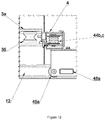
- the platform 3 With the rear part of the back part 33, the platform 3 is attached to the carriage 3a, which is attached to the guide rail 4 with guide wheels 36, as shown in Figure 3 , wherein the said wheels 36 enable the platform 3 to move upwards and downwards along the guide rail 4.
- Figure 3a shows the possible design of the carriage 3a.
- the carriage 3a is actually a plate onto which at least three, preferably five, guide wheels 36 are attached with their position shown in Figure 3a .
- Two other components of the carriage are a lower anchorage of the chain and an angle part on the front part where the carriage is locked onto the guide rail.
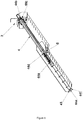
- the guide rail 4 is actually a long element in the approximate shape of the letter L, as shown in Figure 3 .
- Guide rollers 44 are provided within the guide rail 4, wherein the first rollers 44a, 44b, 44c are mounted onto the guide rail itself, while the second rollers 44d, 44e, 44f are mounted into the side of the staircase. The position of two of the first rollers 44b and 44c is visible in Figures 5 and 6 .
- a drive sprocket 45 is mounted onto the lower staircase and is driven with a drive.
- An endless chain or a wire rope 46 is placed onto the guide rollers 44 and the drive sprocket 45, as shown in Figure 3 .
- the length of the longer part 41 of the guide rail 4 is approximately similar to the length of the stationary part (lower staircase) of telescopic passenger stairs.
- Guide rollers 44b, 44c, as well as additional wheels 48a, 48b and 49a, 49b are installed on the shorter part 42 of the guide rail 4.
- the guide rail 4 is guided along the upper staircase with the help of wheels 48a, 48b, 49a and 49b.
- the first pair of wheels 48a, 48b laterally guides the guide rail 4, while the second pair of wheels 49a and 49b guides it vertically.
- the guide rail is additionally equipped with a lock ( Figure 12 ) ensuring that the carriage cannot descend the guide rail unless the latter is in its lowermost position.
- the guide rail is equipped with a clamping block, whose position is determined by the lower staircase and a spring.
- the lower staircase pushes onto the clamping block, overcoming the spring and removing the block out of the way of the carriage.
- the carriage pushes the guide rail 4 upwards, it is moved away from the lower staircase.
- the spring pushes the block behind the carriage, thus preventing the carriage from descending the guide rail 4.
- the longer part 41 of the guide rail 4 has a shape as shown in Figure 4 and comprises an internal U-profile 43a, equipped with one of the first rollers 44a, and of an external C-profile 43b, in the middle of which the internal profile is attached.
- the endless chain or wire rope 46 mostly runs within the internal U-profile 43a.
- the U-profile 43a ensures higher rigidity of the guide rail 4, so it is less susceptible to lateral bending due to the weight of the lifting platform 3 and the potential passenger on a wheelchair. Since the guide rail 4 is guided along the rail of the upper staircase, the rigidity is thus additionally increased. If the guide rail 4 had been made of a suitably rigid material or if it were shaped in a way enabling a higher degree of rigidity, the guiding along the rail of the upper staircase could be omitted.
- the course of the chain 46 enables the carriage to run along the stationary guide rail 4 and also makes it possible for the guide rail to function telescopically when the carriage is on the top of the guide rail.
- the chain runs within the guide rail 4 over at least one sprocket (chain wheel) and at least three guide rollers that can also be sprockets.
- the chain runs over one sprocket 45 and over six guide rollers 44a, 44b, 44c, 44d, 44e and 44f, wherein the roller next to the guiding roller 44e is used to tension the chain.
- the sprocket 45 and two guide rollers 44e, 44f are located on the lowermost part of the lower staircase (one of the rollers is a tension roller); the upper part of the lower staircase is equipped with one guide roller 44d.
- Three guide rollers for the chain are installed onto the guide rail - two of them at the uppermost part 44b, c, and one of them on the lower part of the guide rail 44a. The chain is attached to the carriage in the part under the guide rail.
- the drive sprocket 45 can be powered electrically, manually, or both electrically and manually. Preferably, it is driven both electrically and manually, in order to allow removal or emergency use of the lift during power outages.
- a double (combined) drive is enabled by a self-locking gear drive with two exits, wherein one of the exits has an electrical motor and the other has a manual drive device with an actuating lever (crank).
- a possible implementation is shown in Figure 11 . The lever may be removed and is not attached to the drive during normal operation. It would be possible to implement a hydraulic drive; however, from the point of view of construction, this solution is both more complicated and more expensive.
- the lift 2 further comprises a brake, which stops the movement of the platform 3 and/or the guide rail 4.
- Primary controls for operating the lift are installed on the upper platform and can, additionally, also be installed on the platform itself. Secondary controls may also be provided at the bottom of the stairs.
- the transfer to the upper, telescopic part of the stai rs in case of known solutions presents a problem in the course of the rail along which the platform is travelling. It must be possible for the platform to shift from the lower staircase of the stairs to the upper staircase.
- the present invention solves this problem with the lift 2 allowing the platform 3 to travel along the stationary (lower) staircase 11 of the telescopic stairs on the guide rail 4 itself; when it reaches the highest point of the guide rail 4, which matches the end of the bottom staircase 11 of the stairs 1, the platform 3 locks itself in place, while the movement of the entire guide rail 4 is activated.
- the platform 3 Since the platform 3 travels to the uppermost part of the guide rail 4, it first reaches the end of the staircase 1 or the upper platform 13 of the staircase 1, which is connected to the doorstep of the plane. At this point, the movement of the guide rail 4 is stopped and the position is fixed by the self-locking gear drive that enables stopping of the guide rail at any point.
- the movable guide rail 4 thus solves the problem of movement of the platform 3 regardless of the degree of extension of the telescopic staircase.
- two important factors contributing to the passenger's welfare during boarding with the lifting platform 3 are the comfort and the feeling of being far away from the ground.
- the comfort is ensured with the rigid guiding system enabling a smooth running of the carriage 3a and with the drive to control speed.
- the feeling of not being far away from the ground is provided by the lifting platform 3 as it travels a little above the staircase.
- the lifting platform 3 passes over the stairs of the upper staircase, the travelling height of the platform 3 would increase significantly, thus also increasing the feeling of being far away from the ground, if there were no measures taken to prevent that.
- the lifting platform 3 above the intermediate platform is moved towards the stairs of the upper staircase and then the platform continues its way upwards at a similar distance from the staircase as in the lower staircase.
- the implementation of the horizontal movement is shown in Figures 7 and 8 .
- the horizontal movement is enabled by the plate 5 for horizontal shift, attached to the plate of the carriage 3a, onto which rails 51a, b are attached above and below, wherein the platform 3 is equipped with four suitable wheels (minimally three or more) on the back part 33, making it possible to move the lifting platform 3 through the rails 51a, b of the horizontal shift plate 5.
- the plate 5 is separated from the carriage 3a in order to enable the storage of the lifting platform 3 outside of the area of the staircase.
- the plate 5 is provided with two teeth used to fix the platform 3 onto the carriage 3a, and a lock 3b for securing the lifting platform 3 onto the carriage 3a, as it is shown in Figure 8a .
- the rail 6 on the lower staircase above the intermediate platform is present, as well as two wheels 33a, 33b at the back part 33 of the platform 3; said components simultaneously deactivate the friction brake on the rail 6, which is normally used to prevent unpredictable movements of the lifting platform ( Figures 8a, 8b and 8c ).
- the rail 6 is installed onto the lower staircase above the intermediate platform at an angle allowing the lifting platform 3 to overcome the distance of the intermediate platform, which is approximately the height of one step.
- the shift enables passage of the lifting platform 3 onto the upper platform of the passenger stairs, even when the stairs are only extended to a height of one step.
- the wheels are located on a carrier, which is rotatably mounted onto the axes on the back part of the lifting platform 3 and is connected with the friction brake via the axis and the lever.
- the position of the wheels 33a, 33b, which are not in contact with the rail 6, is determined by the connection onto the friction brake.
- the wheels are in a neutral position and the friction brake is activated.
- one of the wheels makes contact (the upper wheel when descending, the lower wheel when ascending); through further movement of the platform 3, the wheels rotate around the axis of the support due to the initial contact (counter-clockwise, in line with Figure 8a or 8b ), and the movement deactivates the brake via a lever. Further movement along the guide rail 4 provokes a horizontal movement of the lifting platform 3 due to the fact that the wheels are aligned with the rack on the lower staircase.
- the carriage 3a and the horizontal shift plate 5 with rails 51a, b do not have to be two separate pieces, but can instead be one suitably manufactured piece. If the horizontal shift system is either not necessary or wanted, the rail and wheels do not have to be built into the lower staircase, and the lifting platform 3 can be permanently installed onto the carriage 3a. Using certain adjustments (a longer ramp of the platform on the upper side, a different form of the carriage and the back part of the lifting platform), the system still allows boarding of passengers. If the lifting platform is stored on the staircase and does not have the horizontal shift, the lift does not need a carriage; instead, the wheels of the carriage 36 can be installed onto the back part 33 of the lifting platform.
- the lift 2 can be built into the side 111 of the telescopic passenger stairs 1, namely into its stationary part 11.
- the lift 2 is already installed during manufacture of the telescopic passenger stairs 1.
- the lower staircase is the main bearing part of the lift according to the invention.
- the side allows installation of the guide wheels 47 for the guide rail 4, and also enables installation of guide wheels 44d,e,f, the drive sprocket 45 and the drive (cylindrical gearing, electric motor) for the endless chain 46.
- the upper staircase serves as a rail for the guide rail 4 as it moves along the extended stai rcase.
- the invention allows the platform 3 to be stored as shown in Figure 10 when the lift according to the invention is installed onto the telescopic passenger stairs; said storage shall preferably be implemented onto the upper platform representing the upper staircase of the telescopic stairs, thus only leaving the guide rail 4 and the carriage 3a at the bottom of the lower staircase of the stairs.
- the top of the upper part of the staircase is provided with an arm 8, which grabs the platform 3 with a raised base part 31 onto two hooks 81 and lifts it from the carriage 3a.
- the lock of the platform onto the carriage must be released.
- said arm 8 turns around the axis, thus moving the platform into storage space 9, which is preferably shaped as a crate with a tarp or doors.
- the lift for telescopic passenger stairs solves the technical problem with a movable guide rail installed into the lower staircase, the rail being able to move up to the top of the upper staircase if needed.
- the guide rail in the lower, stationary staircase serves as a fixed guide rail for the platform, onto which the passenger in a wheelchair is wheeled, while the guide rail in the upper staircase of the stairs is led along the rail, onto which the guide rail is connected by means of wheels.
- the present invention enables boarding of passengers in wheelchairs and disabled passengers in a safe and reliable manner. At the same time, the movement of the platform into the position of non-use allows other passengers to board the plane as usual, without disturbance.
Landscapes
- Engineering & Computer Science (AREA)
- Mechanical Engineering (AREA)
- Health & Medical Sciences (AREA)
- Public Health (AREA)
- Aviation & Aerospace Engineering (AREA)
- Transportation (AREA)
- Structural Engineering (AREA)
- Automation & Control Theory (AREA)
- Life Sciences & Earth Sciences (AREA)
- Animal Behavior & Ethology (AREA)
- General Health & Medical Sciences (AREA)
- Veterinary Medicine (AREA)
- Types And Forms Of Lifts (AREA)
Description
- The present invention belongs to the field of workflows and transport, more precisely to the field of devices for boarding passengers on aeroplanes. The invention relates to a lift for telescopic passenger stairs enabling disabled passengers with impaired mobility to board a plane and to telescopic aeroplane passenger stairs with the said lift.
- Every day, airports and airport ground staff face issues related to disabled and physically handicapped passengers, whether this is due to injuries or due to excess weight. If boarding takes place via a boarding bridge, these passengers can board in the same way as other passengers; in all other cases, however, a special boarding process for disabled persons must be performed, which is often a time-consuming and costly procedure.
- In addition to bridges, the most widespread manner in which passengers board planes is through passenger stairs, which can either be in one piece, one piece with adjustable height (so-called parallelogram stairs), or telescopic stairs, the height of which is adjusted by pulling out the telescopic part and tilting the stairs. These types of stairs are well known and passengers can use them to ascend aboard a plane. Stairs with a built-in escalator are also known, so that the passenger's activity is not needed. These stairs are not suitable for disabled passengers since they cannot use the stairs, while a wheelchair cannot be safely placed onto the escalator.
- Currently, the most commonly used devices for boarding disabled persons are special elevators, so-called ambulance lifts, which are vehicles with a platform that can be moved upwards or downwards vertically, thus enabling the disabled person to bring his/her wheelchair to the doorstep of the aeroplane and then simply drive it inside. Such vehicles are expensive and are therefore not suitable for smaller airports where the number of disabled passengers is not high.
- Ramps with an inclined surface replacing the stairs have also been in use; wheelchairs can also move on this ramp, but due to their small inclination, such ramps are extremely long or coiled, once or multiple times.
- The general technical problem solved by the present invention is therefore how to design a lifting device enabling safe and reliable boarding of passengers on wheelchairs or passengers with reduced mobility, wherein the device shall allow to be mounted and used on telescopic passenger stairs. At the same time, normal transition of passengers on the stairs, when the lift is not in use, has to be ensured.
- On their website, the company AccessAir displays classic one-piece stairs with a fixed height and a platform for wheelchairs that can be moved along guide rails fixed onto one of the sides of the stairs. The platform can be controlled remotely or via a stationary operating station on the upper platform of the stairs, making it possible for the platform to stop at any height. The platform is foldable (collapsible) in order to take up as little space as possible. The website also states that the solution can be used for telescopic stairs; however, the construction in such case is not explained.
- Platforms for wheelchairs, which can be used on one-piece stairs with adjustable height, are known. Document
DE20219336 U1 describes height-adjustable passenger stairs with a wheelchair platform that can be moved up and down the stairs via a guide rail installed into the side wall, running along the length of the stairs. DocumentDE10336449 describes a solution of moving the wheelchair platform up and down the stairs via guide rails installed into both stai rails. - Other known solutions are telescopic stairs with an additional guide rail, along which the platform carrying a wheelchair can be moved. However, said movement is only enabled if the telescopic stairs are in either of their end positions, namely completely extended or completely folded. Such stairs are manufactured by the company Sinfonia. Since aeroplanes are of various heights, which consequently means that their doors are also located at different heights, it must be ensured that the solution also functions on all intermediate stages during the extension of the telescopic part.
- Patent application
WO8101397 - The aim of the invention is thus to design a device that can be built into telescopic passenger stairs and that will enable the platform with a wheelchair to travel from the floor to the upper platform, regardless of the degree of extension of the telescopic stairs. The device must function in a reliable and safe manner, whereby the platform is preferably not located too high above the stairs. At the same time, the device has to enable simple removal of the wheelchair platform in order to allow boarding of other passengers.
- Typical telescopic stairs comprise a lower and upper staircase, between which an intermediate platform is located to ensure passage regardless of the degree of extension of the stairs. A top platform is provided at the top of the stairs, the height of which can be adjusted by extending the stairs and levelled with the doorstep of the plane. Entire stairs are usually installed onto the movable system, mostly onto a suitable vehicle.
- The design of the lift, which has to be raised and lowered on the telescopic stairs regardless of the degree of extension, must overcome the key problem of the variable length of the stairs, which means various lengths of the path to be travelled by the lifting platform. Additionally, in some designs the upper staircase is wider than the lower staircase. As a consequence, a lateral offset is created on the path of the lifting platform, which has to be addressed at least for telescopic stairs. Furthermore, the part between the lower and upper staircases (the area of the intermediate platform) creates an altitude or a length offset on the path of the lifting platform, which needs to be solved in order to increase the safety of the passenger.
- A lift according to the invention is a lift according to
claim 1. - The essence of the lift for telescopic aeroplane passenger stairs enabling passengers in wheelchairs to board a plane is in that it contains a folding (collapsible) platform onto which a wheelchair can be wheeled, wherein the platform is mounted to a guide rail that can be built into one of the sides of the lower staircase of the telescopic stairs. The lift according to the invention enables the platform to move along the guide rail with the help of guide rollers (wheels), as well as the movement of the entire guide rail together with the platform, along the telescopic (upper) staircase of the stairs, regardless of its degree of extension, with the help of an endless chain, guide rollers, drive sprocket and drive, wherein the movement of the entire guide rail is only activated when the platform reaches the highest point of the guide rail. In the area of the upper staircase, the guide rail pushes the carriage and consequently the lifting platform. Along the upper staircase, the guide rail is installed into a rail, which represents a standard component of the upper staircases of telescopic stairs, as the carrying wheels of the lower part are running over that part. The movement of the guide rail along the said track is enabled by at least three guide wheels installed in such a way as to ensure both vertical and lateral guiding. An advantage of the lift according to the invention is that it comprises only one drive system, which is installed into the lower part of the lower staircase. All movement (including the movement of the platform) arises from the movement of the endless chain and is based on the track-wheel system. The guide rail moves along the lower and the upper staircase with the help of guide rollers, making it possible to continuously function along the entire length of telescopic stairs, thus ensuring a well-supported guide rail in all positions. Accordingly, the problem of moving the lift regardless of the degree of extension of the telescopic stairs is solved.
- An embodiment of the lift for telescopic passenger stairs enabling passengers in wheelchairs to board a plane comprises:
- a foldable lifting platform onto which a wheelchair can be wheeled, wherein said platform has a base, two or three inclined ramps, a back part and two safety barriers, and can optionally also have a seat,
- wherein the back of the platform is attached to a carriage, the main component of which is a plate onto which at least three, preferably five, guide wheels are attached,
- wherein the carriage is attached to the guide rail via guide wheels, thus enabling the movement of the carriage and, thus the movement of the platform along the guide rail,
- the guide rail has a lock for locking when the platform lifts the guide rail from the lower staircase and unlocking when the guide rail returns back onto the lower staircase,
- the said guide rail is a long element of an essentially rectangular shape with a C-shaped cross-section and a shorter part on one side, the guide rail also being equipped with at least two, preferably three, guide rollers onto which an endless chain or a wire rope is installed within the guide rail, wherein said endless chain or wire rope is driven via a self-locking gear train enabling the platform to stop at any position,
- a drive driving the lift,
- a brake,
- wherein the platform can be moved along the guide rail and the guide rail can be moved along the upper staircase of the telescopic stairs when the platform is at the highest point of the guide rail.
- In addition, the lift can also have a lateral offset and a horizontal shift. If needed, the said lateral offset is solved by installing the guide rail onto the rail of the lower staircase in a way that makes it possible to move along the lower staircase unimpeded. In order to move the guide rail and the platform in one single plane on the upper and the lower part of the stairs, the guide rail can be optionally equipped with at least one distancing element.
- The horizontal movement is not an essential feature the platform could move without it. However, in the absence of the horizontal shift the platform would be placed higher above the stair in the upper staircase, meaning that at least the upper inclined plane of the lifting platform should have been longer. The horizontal shift is facilitated with wheels on the back of the lifting platform and with tracks on the carriage and is initiated with a rail above the intermediate platform and guide wheels on the lifting platform. The guide wheels installed onto the carriage on the central axis catch the rail in the area of the intermediate platform, turn around the central axis in order to release the brake, and move the platform due to connection with the rail. At the end of the rail, they return into the initial position, while the brakes and the position of the platform on the additional guide rail lock themselves. The additional guide rail is placed onto the carriage, which moves on the (main) guide rail via its own wheels (guide rollers). In order to ensure safety before moving outside of the area of the main platform, a brake is installed between the lifting platform and the rail for the horizontal movement, wherein said brake is released when the guide wheels are outside of their neutral position due to the contact with the rail. The brake is needed due to the variable inclination of the stairs which, in turn, provokes a variable inclination of the rail for the horizontal movement.
- The invention will be described below in detail using figures, which show:
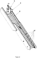
- Figure 1:
- The lift according to the invention, placed onto the telescopic passenger stairs in its initial position when the seat is located at the bottom of the stairs
- Figure 2:
- The lift according to the invention, placed onto the telescopic passenger stairs in its final position when the seat is located at the top of the stairs
- Figure 3:
- The guide rail
- Figure 3a:
- The carriage
- Figure 4:
- Side view of the guide rail profile
- Figure 5:
- Interior of the guide rail when it is located on the lower (stationary) staircase of the telescopic passenger stairs
- Figure 6:
- Inside of the guide rail when it is located on the upper (telescopic) staircase of the telescopic passenger stairs
- Figure 7a:
- Initial state of the horizontal movement of the platform from the side of the stairs
- Figure 7b:
- Final state of the horizontal movement of the platform from the side of the stairs
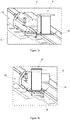
- Figure 8a:
- A back view of the lifting platform with a plate ensuring horizontal movement
- Figure 8b:
- The initial state of the horizontal movement of the platform from the interior of the wall of the stairs
- Figure 8c:
- The final state of the horizontal movement of the platform from the interior of the wall of the stairs
- Figure 9:
- The rail above the intermediate platform ensuring horizontal movement
- Figure 10:
- The crate and arm enabling the storage of the lifting platform when it is not in use
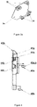
- Figure 11:
- Self-locking cylindrical gearing with an electric motor and a hand-operated drive
- Figure 12:
- Lock for locking the carriage to the guide rail
- The figures and embodiments described below serve as illustrations of the solution of the technical problem and can be adapted without derogating from the basic general design of the lift as defined above and in the claims.
- As shown in
Figures 1 and2 , the lift comprises a folding (collapsible)platform 3 onto which a wheelchair can be led, wherein the platform comprises: - a
base 31, - two or three
inclined ramps - a
back part 33, wherein the lower part of the back is attached to thebase 31, and - folding
safety barriers back part 33. - With the rear part of the
back part 33, theplatform 3 is attached to thecarriage 3a, which is attached to theguide rail 4 withguide wheels 36, as shown inFigure 3 , wherein the saidwheels 36 enable theplatform 3 to move upwards and downwards along theguide rail 4.Figure 3a shows the possible design of thecarriage 3a. Thecarriage 3a is actually a plate onto which at least three, preferably five, guidewheels 36 are attached with their position shown inFigure 3a . Two other components of the carriage are a lower anchorage of the chain and an angle part on the front part where the carriage is locked onto the guide rail. - The
guide rail 4 is actually a long element in the approximate shape of the letter L, as shown inFigure 3 . Guide rollers 44 are provided within theguide rail 4, wherein thefirst rollers second rollers first rollers Figures 5 and6 . Within theguide rail 4, adrive sprocket 45 is mounted onto the lower staircase and is driven with a drive. An endless chain or awire rope 46 is placed onto the guide rollers 44 and thedrive sprocket 45, as shown inFigure 3 . The length of thelonger part 41 of theguide rail 4 is approximately similar to the length of the stationary part (lower staircase) of telescopic passenger stairs.Guide rollers additional wheels shorter part 42 of theguide rail 4. Theguide rail 4 is guided along the upper staircase with the help ofwheels wheels guide rail 4, while the second pair ofwheels Figure 12 ) ensuring that the carriage cannot descend the guide rail unless the latter is in its lowermost position. The guide rail is equipped with a clamping block, whose position is determined by the lower staircase and a spring. When theguide rail 4 is in its lowermost position, the lower staircase pushes onto the clamping block, overcoming the spring and removing the block out of the way of the carriage. When the carriage pushes theguide rail 4 upwards, it is moved away from the lower staircase. At that time, the spring pushes the block behind the carriage, thus preventing the carriage from descending theguide rail 4. - The
longer part 41 of theguide rail 4 has a shape as shown inFigure 4 and comprises an internal U-profile 43a, equipped with one of thefirst rollers 44a, and of an external C-profile 43b, in the middle of which the internal profile is attached. The endless chain orwire rope 46 mostly runs within the internal U-profile 43a. The U-profile 43a ensures higher rigidity of theguide rail 4, so it is less susceptible to lateral bending due to the weight of thelifting platform 3 and the potential passenger on a wheelchair. Since theguide rail 4 is guided along the rail of the upper staircase, the rigidity is thus additionally increased. If theguide rail 4 had been made of a suitably rigid material or if it were shaped in a way enabling a higher degree of rigidity, the guiding along the rail of the upper staircase could be omitted. - The course of the
chain 46 enables the carriage to run along thestationary guide rail 4 and also makes it possible for the guide rail to function telescopically when the carriage is on the top of the guide rail. The chain runs within theguide rail 4 over at least one sprocket (chain wheel) and at least three guide rollers that can also be sprockets. In a possible embodiment, the chain runs over onesprocket 45 and over sixguide rollers roller 44e is used to tension the chain. Thesprocket 45 and twoguide rollers guide roller 44d. Three guide rollers for the chain are installed onto the guide rail - two of them at theuppermost part 44b, c, and one of them on the lower part of theguide rail 44a. The chain is attached to the carriage in the part under the guide rail. The course of the chain over the guide rollers depicted inFigures 3 ,5 and6 allows telescopic movement of the guide rail, ensuring the carriage to move along the entire length of the static guide rail; as it reaches the highest point of the guide rail, the chain along with the carriage pulls the guide rail along the length of the upper staircase. Hence, the carriage can travel along the full length of the telescopic stairs, regardless of its degree of extension. - The movement of the guide rail upwards along the stairs is enabled by
wheels 47; during said upwards movement, the distance between theguide rollers guide rollers Figures 5 and6 . - The
drive sprocket 45 can be powered electrically, manually, or both electrically and manually. Preferably, it is driven both electrically and manually, in order to allow removal or emergency use of the lift during power outages. A double (combined) drive is enabled by a self-locking gear drive with two exits, wherein one of the exits has an electrical motor and the other has a manual drive device with an actuating lever (crank). A possible implementation is shown inFigure 11 . The lever may be removed and is not attached to the drive during normal operation. It would be possible to implement a hydraulic drive; however, from the point of view of construction, this solution is both more complicated and more expensive. If the platform stops during movement on the guide rail, for example, due to a failure of the drive (electrical motor or any other optional drive), the self-locking gear drive prevents the drive sprocket from turning, thus also preventing the movement of the chain and the platform. The lift 2 further comprises a brake, which stops the movement of theplatform 3 and/or theguide rail 4. Primary controls for operating the lift are installed on the upper platform and can, additionally, also be installed on the platform itself. Secondary controls may also be provided at the bottom of the stairs. - When the lift 2 according to the invention is installed into the
side wall 111 of thestai rs 1, the transfer to the upper, telescopic part of the stai rs in case of known solutions presents a problem in the course of the rail along which the platform is travelling. It must be possible for the platform to shift from the lower staircase of the stairs to the upper staircase. The present invention solves this problem with the lift 2 allowing theplatform 3 to travel along the stationary (lower)staircase 11 of the telescopic stairs on theguide rail 4 itself; when it reaches the highest point of theguide rail 4, which matches the end of thebottom staircase 11 of thestairs 1, theplatform 3 locks itself in place, while the movement of theentire guide rail 4 is activated. Since theplatform 3 travels to the uppermost part of theguide rail 4, it first reaches the end of thestaircase 1 or theupper platform 13 of thestaircase 1, which is connected to the doorstep of the plane. At this point, the movement of theguide rail 4 is stopped and the position is fixed by the self-locking gear drive that enables stopping of the guide rail at any point. - The
movable guide rail 4 thus solves the problem of movement of theplatform 3 regardless of the degree of extension of the telescopic staircase. In addition, two important factors contributing to the passenger's welfare during boarding with thelifting platform 3 are the comfort and the feeling of being far away from the ground. The comfort is ensured with the rigid guiding system enabling a smooth running of thecarriage 3a and with the drive to control speed. The feeling of not being far away from the ground is provided by thelifting platform 3 as it travels a little above the staircase. When thelifting platform 3 passes over the stairs of the upper staircase, the travelling height of theplatform 3 would increase significantly, thus also increasing the feeling of being far away from the ground, if there were no measures taken to prevent that. In order to do so, thelifting platform 3 above the intermediate platform is moved towards the stairs of the upper staircase and then the platform continues its way upwards at a similar distance from the staircase as in the lower staircase. The implementation of the horizontal movement is shown inFigures 7 and8 . - The horizontal movement is enabled by the
plate 5 for horizontal shift, attached to the plate of thecarriage 3a, onto which rails 51a, b are attached above and below, wherein theplatform 3 is equipped with four suitable wheels (minimally three or more) on theback part 33, making it possible to move thelifting platform 3 through therails 51a, b of thehorizontal shift plate 5. Preferably, theplate 5 is separated from thecarriage 3a in order to enable the storage of thelifting platform 3 outside of the area of the staircase. For storage, theplate 5 is provided with two teeth used to fix theplatform 3 onto thecarriage 3a, and a lock 3b for securing thelifting platform 3 onto thecarriage 3a, as it is shown inFigure 8a . - In order to move the
lifting platform 3 on therails 51a, b of thehorizontal shift plate 5, therail 6 on the lower staircase above the intermediate platform is present, as well as twowheels back part 33 of theplatform 3; said components simultaneously deactivate the friction brake on therail 6, which is normally used to prevent unpredictable movements of the lifting platform (Figures 8a, 8b and8c ). Therail 6 is installed onto the lower staircase above the intermediate platform at an angle allowing thelifting platform 3 to overcome the distance of the intermediate platform, which is approximately the height of one step. Thus, the shift enables passage of thelifting platform 3 onto the upper platform of the passenger stairs, even when the stairs are only extended to a height of one step. The wheels are located on a carrier, which is rotatably mounted onto the axes on the back part of thelifting platform 3 and is connected with the friction brake via the axis and the lever. The position of thewheels rail 6, is determined by the connection onto the friction brake. When the carriage with the lifting platform moves to contact the rail (from below or above), the wheels are in a neutral position and the friction brake is activated. First, one of the wheels makes contact (the upper wheel when descending, the lower wheel when ascending); through further movement of theplatform 3, the wheels rotate around the axis of the support due to the initial contact (counter-clockwise, in line withFigure 8a or 8b ), and the movement deactivates the brake via a lever. Further movement along theguide rail 4 provokes a horizontal movement of thelifting platform 3 due to the fact that the wheels are aligned with the rack on the lower staircase. - If removal of the lifting platform from the staircase is not needed due to storage of the folding platform on the stairs, the
carriage 3a and thehorizontal shift plate 5 withrails 51a, b do not have to be two separate pieces, but can instead be one suitably manufactured piece. If the horizontal shift system is either not necessary or wanted, the rail and wheels do not have to be built into the lower staircase, and thelifting platform 3 can be permanently installed onto thecarriage 3a. Using certain adjustments (a longer ramp of the platform on the upper side, a different form of the carriage and the back part of the lifting platform), the system still allows boarding of passengers. If the lifting platform is stored on the staircase and does not have the horizontal shift, the lift does not need a carriage; instead, the wheels of thecarriage 36 can be installed onto theback part 33 of the lifting platform. - The lift 2 according to any of the embodiments can be built into the
side 111 of thetelescopic passenger stairs 1, namely into itsstationary part 11. Preferably, the lift 2 is already installed during manufacture of thetelescopic passenger stairs 1. The lower staircase is the main bearing part of the lift according to the invention. The side allows installation of theguide wheels 47 for theguide rail 4, and also enables installation ofguide wheels 44d,e,f, thedrive sprocket 45 and the drive (cylindrical gearing, electric motor) for theendless chain 46. The upper staircase serves as a rail for theguide rail 4 as it moves along the extended stai rcase. - The invention allows the
platform 3 to be stored as shown inFigure 10 when the lift according to the invention is installed onto the telescopic passenger stairs; said storage shall preferably be implemented onto the upper platform representing the upper staircase of the telescopic stairs, thus only leaving theguide rail 4 and thecarriage 3a at the bottom of the lower staircase of the stairs. In order to store theplatform 3, the top of the upper part of the staircase is provided with anarm 8, which grabs theplatform 3 with a raisedbase part 31 onto twohooks 81 and lifts it from thecarriage 3a. At the same time, the lock of the platform onto the carriage must be released. Then, saidarm 8 turns around the axis, thus moving the platform intostorage space 9, which is preferably shaped as a crate with a tarp or doors. - The lift for telescopic passenger stairs solves the technical problem with a movable guide rail installed into the lower staircase, the rail being able to move up to the top of the upper staircase if needed. The guide rail in the lower, stationary staircase serves as a fixed guide rail for the platform, onto which the passenger in a wheelchair is wheeled, while the guide rail in the upper staircase of the stairs is led along the rail, onto which the guide rail is connected by means of wheels. The present invention enables boarding of passengers in wheelchairs and disabled passengers in a safe and reliable manner. At the same time, the movement of the platform into the position of non-use allows other passengers to board the plane as usual, without disturbance.
Claims (15)
- A lift for telescopic passenger stairs enabling passengers with reduced mobility to board a plane, wherein said lift comprises:- a folding platform (3) onto which a wheelchair can be wheeled;- the platform (3) being attached to a guide rail (4) with its back part (33) using at least three guide wheels (36) for moving the platform (3) along the guide rail (4);
characterized in that- the guide rail (4) is shaped as a long element of an essentially rectangular shape with a cross-section in the shape of a letter C and with a shorter part (42) on one end ; and the lift further comprises:- an endless chain or a wire rope (46), running within the guide rail (4) on at least one sprocket (45) and at least three guide rollers (44), which can also be sprockets, wherein said endless chain or wire rope (46) is driven via a drive through a self-locking gear drive for stopping the platform (3) at any point;- the said guide rail (4) having a lock for locking the platform (3) in place, when it reaches the top of the guide rail (4); andwherein the guide rail (4) is arranged to be built into one of the sides of telescopic passenger stairs, and
wherein the endless chain or wire rope (46) within the guide rail (4) enables the platform (3) to move along the guide rail (4) when the platform (3) is in the area of a lower staircase of telescopic stairs, and movement of the guide rail (4) along an upper staircase of telescopic stairs when the platform (3) is at the uppermost point of the guide rail (4), so that the chain pulls the guide rail (4) upwards with the platform (3). - The lift according to claim 1, characterised in that the platform (3) is attached to the guide rail (4) via a carriage (3a), which is essentially a plate onto which at least three, preferably five, guide wheels (36) and an anchorage of the said endless chain or wire rope (46) are attached, wherein the carriage (3a) allows movement of the platform (3) upwards or downwards along the guide rail (4) and allows the chain to pull the guide rail (4) upwards via the carriage (3a) and the platform (3).
- The lift according to claim 1 or 2, characterised in that it further contains a brake for terminating movement of the platform (3) and/or the guide rail (4).
- The lift according to any of the preceding claims, characterised in that the longer part of the guide rail (4) comprises an external profile (43b) in the shape of a letter C, and an internal profile (43a) in the shape of a letter U.
- The lift according to any of the preceding claims, characterised in that guide rollers (44) are installed within the guide rail (4), wherein first rollers (44a, 44b, 44c) are mounted onto the guide rail itself, and second rollers (44d, 44e, 44f), as well as the drive sprocket (45), are arranged to be mounted onto the side part of the lower part of telescopic stairs; in that the rollers (44e, 44f) and the drive sprocket (45) are arranged to be mounted onto the lowermost part of the staircase, while one of the second rollers (44d) is arranged to be installed onto the upper part of the staircase; in that one of the first rollers (44a) is to be installed onto the lower part, while two of first rollers (44b, 44c) are arranged to be installed onto the shorter part (42) of the guide rail (4) where additional wheels (48a, 48b and 49a, 49b) are mounted, wherein the guide rail (4) is guided onto the upper staircase with additional wheels (48a, 48b, 49a and 49b).
- The lift according to any of the preceding claims, characterised in that the guide rail (4) with wheels is arranged to be guided on a rail of the upper staircase.
- The lift according to any of the preceding claims, characterised in that the drive can be electrical, manual, or a combination of both.
- The lift according to claim 7, characterised in that the combined drive is enabled with a self-locking gear drive with two exits, wherein one of the exits has an electrical motor and the other has a manual drive device with an actuated crank.
- The lift according to any of the preceding claims, characterised in that the platform (3) has a base part (31), two or three inclined ramps (32a, 32b, 32c), which are movably attached onto the base part (31), a back part (33), the bottom part of which is attached onto the base part (31), and safety barriers (34a, 34b) attached to the left and the right side of the back part (33); and the platform (3) optionally has a foldable seat mounted to the front surface of the back part (33).
- The lift according to any claim from 2 to 9, characterised in that a plate (5) for a horizontal shift is attached to the plate of the carriage (3a), wherein said plate has rails (51a, 51b) mounted onto its upper and lower parts, and wherein the back part (33) of the platform (3) is equipped with at least three additional wheels for moving the lifting platform (3) up and down the rails (51a, 51b) of the horizontal shift plate (5); and in that the lift has a lock (3b) used to securely lock the platform (3) onto the carriage (3a).
- Telescopic passenger stairs comprising the lift according to any of the preceding claims, wherein the lift is installed into one of the sides of the staircase in the lower, stationary part of the stairs, wherein the guide rail (4) is preferably installed onto the side of the lower part of the telescopic staircase for allowing undisturbed movement upwards on the lower staircase of the stairs.
- The telescopic passenger stairs according to claim 11, characterised in that the guide rail (4) may be provided with at least one distancing element for moving the guide rail (4) and the platform (3) in one single plane on the lower and the upper staircase of the stairs.
- The telescopic passenger stairs according to any claim from 11 to 12, characterised in that shift of the platform (3) along the rails (51a, b) of the horizontal shift plate (5) is enabled by a rail (6) above the intermediate platform of the stairs and with two wheels (33a, 33b) at the back part (33) of the platform (3), which simultaneously deactivate a friction brake on the rail (6) that prevents undesirable movements of the platform; and in that the rail (6) is installed onto the lower staircase above the intermediate platform at an angle allowing the platform (3) to overcome the distance of the intermediate platform, which is approximately the height of one step.
- The telescopic passenger stairs according to any claim from 11 to 13, characterised in that the platform (3) can be stored when the lift is not in use, wherein the platform is preferably stored on the upper platform of the stairs, and wherein the guide rail (4) and the carriage (3a) remain at the bottom of the lower staircase; in that an arm (8) with two hooks (81) for grabbing and lifting the platform (3) from the carriage (3a) is mounted onto the upper platform of the stairs in order to store the platform (3) when the lock of the platform on the carriage is released, wherein said arm (8) can rotate around an axis to store the platform (3) into the storage space (9), which is preferably shaped as a crate with a tarp or doors.
- The telescopic passenger stairs for boarding and disembarking passengers according to any claim from 11 to 14, characterised in that primary controls for operating the lift are installed on the upper platform, and that additional controls can also be installed onto the platform itself and/or onto the bottom of the stairs.
Priority Applications (1)
| Application Number | Priority Date | Filing Date | Title |
|---|---|---|---|
| SI201930071T SI3587332T1 (en) | 2018-06-20 | 2019-06-19 | A lift for telescopic passenger stairs for boarding passengers in wheelchairs on a plane |
Applications Claiming Priority (1)
| Application Number | Priority Date | Filing Date | Title |
|---|---|---|---|
| SI201800143A SI25659A (en) | 2018-06-20 | 2018-06-20 | Telescopic aircraft stairs lift for wheelchair passengers embarqemenet |
Publications (2)
| Publication Number | Publication Date |
|---|---|
| EP3587332A1 EP3587332A1 (en) | 2020-01-01 |
| EP3587332B1 true EP3587332B1 (en) | 2021-03-31 |
Family
ID=66999586
Family Applications (1)
| Application Number | Title | Priority Date | Filing Date |
|---|---|---|---|
| EP19181232.0A Active EP3587332B1 (en) | 2018-06-20 | 2019-06-19 | A lift for telescopic passenger stairs for boarding passengers in wheelchairs on a plane |
Country Status (6)
| Country | Link |
|---|---|
| US (1) | US11311433B2 (en) |
| EP (1) | EP3587332B1 (en) |
| JP (1) | JP7264739B2 (en) |
| DK (1) | DK3587332T3 (en) |
| ES (1) | ES2882879T3 (en) |
| SI (2) | SI25659A (en) |
Families Citing this family (8)
| Publication number | Priority date | Publication date | Assignee | Title |
|---|---|---|---|---|
| IL249002A0 (en) * | 2016-11-16 | 2017-03-30 | Eisenman Orna | Stair lift device |
| JP6354013B1 (en) * | 2017-12-06 | 2018-07-04 | 裕 千田 | Stair lift |
| SI25659A (en) * | 2018-06-20 | 2019-12-31 | Tips d.o.o. | Telescopic aircraft stairs lift for wheelchair passengers embarqemenet |
| US11001475B2 (en) * | 2018-12-28 | 2021-05-11 | Cheng-Chung Chen | Apartment staircase automatic lift |
| CN113175165A (en) * | 2021-05-07 | 2021-07-27 | 安徽锦允新材料科技有限公司 | Intelligent home stair structure assisting wheelchair in climbing |
| CN113387257B (en) * | 2021-07-02 | 2022-09-16 | 山东淼远金属制品有限公司 | Barrier-free passage wheelchair self-service device suitable for disabled people |
| US20230022827A1 (en) * | 2021-07-21 | 2023-01-26 | Hewlett-Packard Development Company, L.P. | Direct Printing and Printer |
| US11945692B1 (en) * | 2022-10-24 | 2024-04-02 | Lewis Young | Electric stair lift |
Family Cites Families (25)
| Publication number | Priority date | Publication date | Assignee | Title |
|---|---|---|---|---|
| US3625306A (en) * | 1970-07-16 | 1971-12-07 | Wollard Aircraft Equipment Inc | Conveyance servicing structure |
| US3664456A (en) * | 1970-07-20 | 1972-05-23 | Wollard Aircraft Equipment Inc | Conveyance servicing structure |
| FR2225335B1 (en) * | 1973-04-10 | 1978-03-03 | Douaisis Ateliers Mecaniques | |
| US3891062A (en) * | 1974-01-07 | 1975-06-24 | Georges Geneste | Telescopic lift for construction works |
| US4438830A (en) * | 1979-06-25 | 1984-03-27 | Born Raymond W | Stairway with fail safe power lift for lading, the infirm, wheelchair patients, and the like |
| FR2470053A1 (en) * | 1979-11-21 | 1981-05-29 | Montini Raoul | MOBILE ELEVATOR COMBINED WITH STAIRS FOR THE TRANSPORT OF THE DISABLED AND PARTICULARLY FOR ACCESS TO AIRCRAFT WITH ADAPTABLE SEAT |
| IT1183935B (en) * | 1985-09-02 | 1987-10-22 | Francesco Bono | SELF-TRANSPORTABLE LIFT WITH TWIN TELESCOPIC ARM |
| US4793437A (en) * | 1987-07-20 | 1988-12-27 | Philip Hanthorn | Portable lift with telescopic booms and load-carrying apparatus |
| US5052521A (en) * | 1988-05-18 | 1991-10-01 | The Cheney Company | Stairway wheelchair lift |
| GB2242412A (en) * | 1990-03-31 | 1991-10-02 | Raymond John Holden | A moving track stairlift. |
| US5125481A (en) * | 1990-09-26 | 1992-06-30 | Hideaki Shibata | Diagonal elevation apparatus |
| NO954872L (en) * | 1995-11-30 | 1997-06-02 | Svein Erik Roeed | Hoisting device |
| US6676358B2 (en) * | 2001-10-19 | 2004-01-13 | Dave W. Smith | Compact folding aircraft passenger ramp |
| US6854147B1 (en) * | 2002-04-05 | 2005-02-15 | George E. Ahlsten | Loading ramp apparatus |
| DE20219336U1 (en) | 2002-12-13 | 2003-02-27 | Thyssen Fahrtreppen GmbH, 22113 Hamburg | Truck-mounted civil aircraft height-adjustable stairs incorporate wheelchair lift platform |
| DE10336449A1 (en) | 2003-08-06 | 2005-05-25 | Losch Airport Equipment Gmbh | Wheelchair lift for access to civil aircraft passenger cabin rides on air stair handrail carriage |
| US7395900B2 (en) * | 2005-01-28 | 2008-07-08 | Richard Murray | Portable wheelchair lift |
| JP2007030677A (en) * | 2005-07-27 | 2007-02-08 | Tcm Corp | Boarding vehicle |
| US7308968B2 (en) * | 2006-02-08 | 2007-12-18 | Orville Douglas Denison | Transportable rescue conveyer |
| JP5105054B2 (en) * | 2007-06-29 | 2012-12-19 | シンフォニアテクノロジー株式会社 | lift device |
| GB2499408B (en) * | 2012-02-14 | 2014-12-03 | Stannah Stairlifts Ltd | Improvements in or relating to stairlifts |
| US9469507B2 (en) * | 2014-05-26 | 2016-10-18 | Drexel University | Modular escalating wheelchair lift |
| US10787342B2 (en) * | 2016-09-27 | 2020-09-29 | Wheelchair Escalators, Llc | Wheelchair lift apparatus |
| JP6354013B1 (en) * | 2017-12-06 | 2018-07-04 | 裕 千田 | Stair lift |
| SI25659A (en) * | 2018-06-20 | 2019-12-31 | Tips d.o.o. | Telescopic aircraft stairs lift for wheelchair passengers embarqemenet |
-
2018
- 2018-06-20 SI SI201800143A patent/SI25659A/en not_active IP Right Cessation
-
2019
- 2019-06-18 JP JP2019113103A patent/JP7264739B2/en active Active
- 2019-06-19 DK DK19181232.0T patent/DK3587332T3/en active
- 2019-06-19 ES ES19181232T patent/ES2882879T3/en active Active
- 2019-06-19 EP EP19181232.0A patent/EP3587332B1/en active Active
- 2019-06-19 SI SI201930071T patent/SI3587332T1/en unknown
- 2019-06-20 US US16/447,840 patent/US11311433B2/en active Active
Also Published As
| Publication number | Publication date |
|---|---|
| SI25659A (en) | 2019-12-31 |
| JP7264739B2 (en) | 2023-04-25 |
| US20190388286A1 (en) | 2019-12-26 |
| DK3587332T3 (en) | 2021-06-21 |
| SI3587332T1 (en) | 2021-09-30 |
| ES2882879T3 (en) | 2021-12-03 |
| US11311433B2 (en) | 2022-04-26 |
| JP2020023306A (en) | 2020-02-13 |
| EP3587332A1 (en) | 2020-01-01 |
Similar Documents
| Publication | Publication Date | Title |
|---|---|---|
| EP3587332B1 (en) | A lift for telescopic passenger stairs for boarding passengers in wheelchairs on a plane | |
| US5425615A (en) | Combination folding stair and platform wheelchair lift | |
| KR101090782B1 (en) | Stair combined use strait type lift device and the operating method | |
| WO2007091461A1 (en) | Vehicle for passenger entry and exit | |
| KR100936020B1 (en) | Low floor wheel chair lift | |
| US10414632B1 (en) | Escalator system for facilitating the transport of goods | |
| JP2005349993A (en) | Boarding ramp vehicle | |
| US8104600B2 (en) | Escalator | |
| RU2540724C2 (en) | Ramp (versions) | |
| RU89848U1 (en) | VERTICAL LIFT FOR DISABLED PEOPLE | |
| WO1997019887A1 (en) | Lift device | |
| KR200290893Y1 (en) | U-shaped shuttle type elevator | |
| KR102529583B1 (en) | Evacuation slides for wheelchair usersn | |
| JP3148482U (en) | Multipurpose stair lift | |
| US5402546A (en) | Access facilitating system for chair assisted passengers embarking or disembarking a small aircraft | |
| JP5088653B2 (en) | Lifting device and bus | |
| US20020074188A1 (en) | Installation for transporting people, in particular those with reduced mobility, and fitting of this installation from notably an escalator | |
| RU183695U1 (en) | Mobile railway lift for people with limited mobility | |
| JP6095410B2 (en) | Barrier-free boarding facility | |
| RU99704U1 (en) | LIFTING DEVICE FOR LANDING AND DEPARTURE OF A PASSENGER IN A WHEELCHAIR INSTALLED IN A RAILWAY CAR | |
| RU2509711C2 (en) | Lifter for straight stair flights | |
| RU175479U1 (en) | A lifting device for boarding and alighting a passenger in a wheelchair, installed in a railway carriage | |
| JP3619519B2 (en) | Vehicle having deck and cabin lifting device | |
| JP2007030677A (en) | Boarding vehicle | |
| RU213311U1 (en) | Passenger lift for persons with disabilities |
Legal Events
| Date | Code | Title | Description |
|---|---|---|---|
| PUAI | Public reference made under article 153(3) epc to a published international application that has entered the european phase |
Free format text: ORIGINAL CODE: 0009012 |
|
| STAA | Information on the status of an ep patent application or granted ep patent |
Free format text: STATUS: THE APPLICATION HAS BEEN PUBLISHED |
|
| AK | Designated contracting states |
Kind code of ref document: A1 Designated state(s): AL AT BE BG CH CY CZ DE DK EE ES FI FR GB GR HR HU IE IS IT LI LT LU LV MC MK MT NL NO PL PT RO RS SE SI SK SM TR |
|
| AX | Request for extension of the european patent |
Extension state: BA ME |
|
| STAA | Information on the status of an ep patent application or granted ep patent |
Free format text: STATUS: REQUEST FOR EXAMINATION WAS MADE |
|
| 17P | Request for examination filed |
Effective date: 20200619 |
|
| RBV | Designated contracting states (corrected) |
Designated state(s): AL AT BE BG CH CY CZ DE DK EE ES FI FR GB GR HR HU IE IS IT LI LT LU LV MC MK MT NL NO PL PT RO RS SE SI SK SM TR |
|
| RIC1 | Information provided on ipc code assigned before grant |
Ipc: B64F 1/315 20060101ALI20201130BHEP Ipc: B66B 9/08 20060101AFI20201130BHEP |
|
| GRAP | Despatch of communication of intention to grant a patent |
Free format text: ORIGINAL CODE: EPIDOSNIGR1 |
|
| STAA | Information on the status of an ep patent application or granted ep patent |
Free format text: STATUS: GRANT OF PATENT IS INTENDED |
|
| INTG | Intention to grant announced |
Effective date: 20210118 |
|
| GRAS | Grant fee paid |
Free format text: ORIGINAL CODE: EPIDOSNIGR3 |
|
| GRAA | (expected) grant |
Free format text: ORIGINAL CODE: 0009210 |
|
| STAA | Information on the status of an ep patent application or granted ep patent |
Free format text: STATUS: THE PATENT HAS BEEN GRANTED |
|
| AK | Designated contracting states |
Kind code of ref document: B1 Designated state(s): AL AT BE BG CH CY CZ DE DK EE ES FI FR GB GR HR HU IE IS IT LI LT LU LV MC MK MT NL NO PL PT RO RS SE SI SK SM TR |
|
| REG | Reference to a national code |
Ref country code: GB Ref legal event code: FG4D Ref country code: CH Ref legal event code: EP |
|
| RIN1 | Information on inventor provided before grant (corrected) |
Inventor name: PUSTAVRH, ROBERT Inventor name: BRATUSA, ROK Inventor name: FERLIN, JANEZ Inventor name: SNEBERGER, SILVO Inventor name: SMOLE, MARJAN |
|
| REG | Reference to a national code |
Ref country code: DE Ref legal event code: R096 Ref document number: 602019003555 Country of ref document: DE Ref country code: AT Ref legal event code: REF Ref document number: 1376734 Country of ref document: AT Kind code of ref document: T Effective date: 20210415 |
|
| REG | Reference to a national code |
Ref country code: IE Ref legal event code: FG4D |
|
| REG | Reference to a national code |
Ref country code: DK Ref legal event code: T3 Effective date: 20210617 |
|
| REG | Reference to a national code |
Ref country code: FI Ref legal event code: FGE |
|
| REG | Reference to a national code |
Ref country code: SE Ref legal event code: TRGR |
|
| REG | Reference to a national code |
Ref country code: NL Ref legal event code: FP |
|
| REG | Reference to a national code |
Ref country code: LT Ref legal event code: MG9D |
|
| PG25 | Lapsed in a contracting state [announced via postgrant information from national office to epo] |
Ref country code: BG Free format text: LAPSE BECAUSE OF FAILURE TO SUBMIT A TRANSLATION OF THE DESCRIPTION OR TO PAY THE FEE WITHIN THE PRESCRIBED TIME-LIMIT Effective date: 20210630 Ref country code: HR Free format text: LAPSE BECAUSE OF FAILURE TO SUBMIT A TRANSLATION OF THE DESCRIPTION OR TO PAY THE FEE WITHIN THE PRESCRIBED TIME-LIMIT Effective date: 20210331 |
|
| PGFP | Annual fee paid to national office [announced via postgrant information from national office to epo] |
Ref country code: LU Payment date: 20210625 Year of fee payment: 3 |
|
| PG25 | Lapsed in a contracting state [announced via postgrant information from national office to epo] |
Ref country code: LV Free format text: LAPSE BECAUSE OF FAILURE TO SUBMIT A TRANSLATION OF THE DESCRIPTION OR TO PAY THE FEE WITHIN THE PRESCRIBED TIME-LIMIT Effective date: 20210331 Ref country code: RS Free format text: LAPSE BECAUSE OF FAILURE TO SUBMIT A TRANSLATION OF THE DESCRIPTION OR TO PAY THE FEE WITHIN THE PRESCRIBED TIME-LIMIT Effective date: 20210331 |
|
| PGFP | Annual fee paid to national office [announced via postgrant information from national office to epo] |
Ref country code: TR Payment date: 20210617 Year of fee payment: 3 |
|
| REG | Reference to a national code |
Ref country code: NO Ref legal event code: T2 Effective date: 20210331 |
|
| PG25 | Lapsed in a contracting state [announced via postgrant information from national office to epo] |
Ref country code: LT Free format text: LAPSE BECAUSE OF FAILURE TO SUBMIT A TRANSLATION OF THE DESCRIPTION OR TO PAY THE FEE WITHIN THE PRESCRIBED TIME-LIMIT Effective date: 20210331 Ref country code: EE Free format text: LAPSE BECAUSE OF FAILURE TO SUBMIT A TRANSLATION OF THE DESCRIPTION OR TO PAY THE FEE WITHIN THE PRESCRIBED TIME-LIMIT Effective date: 20210331 Ref country code: CZ Free format text: LAPSE BECAUSE OF FAILURE TO SUBMIT A TRANSLATION OF THE DESCRIPTION OR TO PAY THE FEE WITHIN THE PRESCRIBED TIME-LIMIT Effective date: 20210331 Ref country code: SM Free format text: LAPSE BECAUSE OF FAILURE TO SUBMIT A TRANSLATION OF THE DESCRIPTION OR TO PAY THE FEE WITHIN THE PRESCRIBED TIME-LIMIT Effective date: 20210331 |
|
| PG25 | Lapsed in a contracting state [announced via postgrant information from national office to epo] |
Ref country code: SK Free format text: LAPSE BECAUSE OF FAILURE TO SUBMIT A TRANSLATION OF THE DESCRIPTION OR TO PAY THE FEE WITHIN THE PRESCRIBED TIME-LIMIT Effective date: 20210331 Ref country code: PT Free format text: LAPSE BECAUSE OF FAILURE TO SUBMIT A TRANSLATION OF THE DESCRIPTION OR TO PAY THE FEE WITHIN THE PRESCRIBED TIME-LIMIT Effective date: 20210802 Ref country code: RO Free format text: LAPSE BECAUSE OF FAILURE TO SUBMIT A TRANSLATION OF THE DESCRIPTION OR TO PAY THE FEE WITHIN THE PRESCRIBED TIME-LIMIT Effective date: 20210331 Ref country code: PL Free format text: LAPSE BECAUSE OF FAILURE TO SUBMIT A TRANSLATION OF THE DESCRIPTION OR TO PAY THE FEE WITHIN THE PRESCRIBED TIME-LIMIT Effective date: 20210331 Ref country code: IS Free format text: LAPSE BECAUSE OF FAILURE TO SUBMIT A TRANSLATION OF THE DESCRIPTION OR TO PAY THE FEE WITHIN THE PRESCRIBED TIME-LIMIT Effective date: 20210731 |
|
| REG | Reference to a national code |
Ref country code: ES Ref legal event code: FG2A Ref document number: 2882879 Country of ref document: ES Kind code of ref document: T3 Effective date: 20211203 |
|
| REG | Reference to a national code |
Ref country code: DE Ref legal event code: R097 Ref document number: 602019003555 Country of ref document: DE |
|
| PG25 | Lapsed in a contracting state [announced via postgrant information from national office to epo] |
Ref country code: AL Free format text: LAPSE BECAUSE OF FAILURE TO SUBMIT A TRANSLATION OF THE DESCRIPTION OR TO PAY THE FEE WITHIN THE PRESCRIBED TIME-LIMIT Effective date: 20210331 Ref country code: MC Free format text: LAPSE BECAUSE OF FAILURE TO SUBMIT A TRANSLATION OF THE DESCRIPTION OR TO PAY THE FEE WITHIN THE PRESCRIBED TIME-LIMIT Effective date: 20210331 |
|
| PLBE | No opposition filed within time limit |
Free format text: ORIGINAL CODE: 0009261 |
|
| STAA | Information on the status of an ep patent application or granted ep patent |
Free format text: STATUS: NO OPPOSITION FILED WITHIN TIME LIMIT |
|
| 26N | No opposition filed |
Effective date: 20220104 |
|
| PG25 | Lapsed in a contracting state [announced via postgrant information from national office to epo] |
Ref country code: IE Free format text: LAPSE BECAUSE OF NON-PAYMENT OF DUE FEES Effective date: 20210619 |
|
| PG25 | Lapsed in a contracting state [announced via postgrant information from national office to epo] |
Ref country code: IS Free format text: LAPSE BECAUSE OF FAILURE TO SUBMIT A TRANSLATION OF THE DESCRIPTION OR TO PAY THE FEE WITHIN THE PRESCRIBED TIME-LIMIT Effective date: 20210731 |
|
| PGFP | Annual fee paid to national office [announced via postgrant information from national office to epo] |
Ref country code: SE Payment date: 20220615 Year of fee payment: 4 Ref country code: NO Payment date: 20220624 Year of fee payment: 4 Ref country code: NL Payment date: 20220626 Year of fee payment: 4 Ref country code: DK Payment date: 20220615 Year of fee payment: 4 |
|
| PGFP | Annual fee paid to national office [announced via postgrant information from national office to epo] |
Ref country code: SI Payment date: 20220614 Year of fee payment: 4 Ref country code: FI Payment date: 20220616 Year of fee payment: 4 Ref country code: BE Payment date: 20220617 Year of fee payment: 4 |
|
| PGFP | Annual fee paid to national office [announced via postgrant information from national office to epo] |
Ref country code: FR Payment date: 20220627 Year of fee payment: 4 |
|
| PGFP | Annual fee paid to national office [announced via postgrant information from national office to epo] |
Ref country code: IT Payment date: 20220630 Year of fee payment: 4 Ref country code: ES Payment date: 20220704 Year of fee payment: 4 Ref country code: DE Payment date: 20220628 Year of fee payment: 4 |
|
| REG | Reference to a national code |
Ref country code: CH Ref legal event code: PL |
|
| PG25 | Lapsed in a contracting state [announced via postgrant information from national office to epo] |
Ref country code: LU Free format text: LAPSE BECAUSE OF NON-PAYMENT OF DUE FEES Effective date: 20220619 Ref country code: LI Free format text: LAPSE BECAUSE OF NON-PAYMENT OF DUE FEES Effective date: 20220630 Ref country code: CH Free format text: LAPSE BECAUSE OF NON-PAYMENT OF DUE FEES Effective date: 20220630 |
|
| PG25 | Lapsed in a contracting state [announced via postgrant information from national office to epo] |
Ref country code: CY Free format text: LAPSE BECAUSE OF FAILURE TO SUBMIT A TRANSLATION OF THE DESCRIPTION OR TO PAY THE FEE WITHIN THE PRESCRIBED TIME-LIMIT Effective date: 20210331 |
|
| PG25 | Lapsed in a contracting state [announced via postgrant information from national office to epo] |
Ref country code: HU Free format text: LAPSE BECAUSE OF FAILURE TO SUBMIT A TRANSLATION OF THE DESCRIPTION OR TO PAY THE FEE WITHIN THE PRESCRIBED TIME-LIMIT; INVALID AB INITIO Effective date: 20190619 Ref country code: GR Free format text: LAPSE BECAUSE OF FAILURE TO SUBMIT A TRANSLATION OF THE DESCRIPTION OR TO PAY THE FEE WITHIN THE PRESCRIBED TIME-LIMIT Effective date: 20210331 |
|
| REG | Reference to a national code |
Ref country code: DE Ref legal event code: R119 Ref document number: 602019003555 Country of ref document: DE |
|
| REG | Reference to a national code |
Ref country code: NO Ref legal event code: MMEP Ref country code: DK Ref legal event code: EBP Effective date: 20230630 |
|
| REG | Reference to a national code |
Ref country code: SE Ref legal event code: EUG |
|
| PG25 | Lapsed in a contracting state [announced via postgrant information from national office to epo] |
Ref country code: FI Free format text: LAPSE BECAUSE OF NON-PAYMENT OF DUE FEES Effective date: 20230619 |
|
| REG | Reference to a national code |
Ref country code: NL Ref legal event code: MM Effective date: 20230701 |
|
| REG | Reference to a national code |
Ref country code: BE Ref legal event code: MM Effective date: 20230630 |
|
| GBPC | Gb: european patent ceased through non-payment of renewal fee |
Effective date: 20230619 |
|
| PG25 | Lapsed in a contracting state [announced via postgrant information from national office to epo] |
Ref country code: NL Free format text: LAPSE BECAUSE OF NON-PAYMENT OF DUE FEES Effective date: 20230701 |
|
| REG | Reference to a national code |
Ref country code: SI Ref legal event code: KO00 Effective date: 20240223 |
|
| PG25 | Lapsed in a contracting state [announced via postgrant information from national office to epo] |
Ref country code: MK Free format text: LAPSE BECAUSE OF FAILURE TO SUBMIT A TRANSLATION OF THE DESCRIPTION OR TO PAY THE FEE WITHIN THE PRESCRIBED TIME-LIMIT Effective date: 20210331 Ref country code: DE Free format text: LAPSE BECAUSE OF NON-PAYMENT OF DUE FEES Effective date: 20240103 Ref country code: GB Free format text: LAPSE BECAUSE OF NON-PAYMENT OF DUE FEES Effective date: 20230619 |
|
| PG25 | Lapsed in a contracting state [announced via postgrant information from national office to epo] |
Ref country code: SI Free format text: LAPSE BECAUSE OF NON-PAYMENT OF DUE FEES Effective date: 20230620 |
|
| PG25 | Lapsed in a contracting state [announced via postgrant information from national office to epo] |
Ref country code: SI Free format text: LAPSE BECAUSE OF NON-PAYMENT OF DUE FEES Effective date: 20230620 Ref country code: SE Free format text: LAPSE BECAUSE OF NON-PAYMENT OF DUE FEES Effective date: 20230620 Ref country code: NO Free format text: LAPSE BECAUSE OF NON-PAYMENT OF DUE FEES Effective date: 20230630 Ref country code: FR Free format text: LAPSE BECAUSE OF NON-PAYMENT OF DUE FEES Effective date: 20230630 Ref country code: BE Free format text: LAPSE BECAUSE OF NON-PAYMENT OF DUE FEES Effective date: 20230630 |
|
| PG25 | Lapsed in a contracting state [announced via postgrant information from national office to epo] |
Ref country code: DK Free format text: LAPSE BECAUSE OF NON-PAYMENT OF DUE FEES Effective date: 20230630 |
|
| REG | Reference to a national code |
Ref country code: ES Ref legal event code: FD2A Effective date: 20240729 |
|
| PG25 | Lapsed in a contracting state [announced via postgrant information from national office to epo] |
Ref country code: IT Free format text: LAPSE BECAUSE OF NON-PAYMENT OF DUE FEES Effective date: 20230619 Ref country code: DK Free format text: LAPSE BECAUSE OF NON-PAYMENT OF DUE FEES Effective date: 20230630 |