EP3585965B1 - Schlossanordnung - Google Patents
Schlossanordnung Download PDFInfo
- Publication number
- EP3585965B1 EP3585965B1 EP17825524.6A EP17825524A EP3585965B1 EP 3585965 B1 EP3585965 B1 EP 3585965B1 EP 17825524 A EP17825524 A EP 17825524A EP 3585965 B1 EP3585965 B1 EP 3585965B1
- Authority
- EP
- European Patent Office
- Prior art keywords
- locking
- rotary latch
- pawl
- contact surface
- lock arrangement
- Prior art date
- Legal status (The legal status is an assumption and is not a legal conclusion. Google has not performed a legal analysis and makes no representation as to the accuracy of the status listed.)
- Active
Links
Images
Classifications
-
- E—FIXED CONSTRUCTIONS
- E05—LOCKS; KEYS; WINDOW OR DOOR FITTINGS; SAFES
- E05B—LOCKS; ACCESSORIES THEREFOR; HANDCUFFS
- E05B85/00—Details of vehicle locks not provided for in groups E05B77/00 - E05B83/00
- E05B85/20—Bolts or detents
- E05B85/24—Bolts rotating about an axis
- E05B85/26—Cooperation between bolts and detents
-
- E—FIXED CONSTRUCTIONS
- E05—LOCKS; KEYS; WINDOW OR DOOR FITTINGS; SAFES
- E05B—LOCKS; ACCESSORIES THEREFOR; HANDCUFFS
- E05B77/00—Vehicle locks characterised by special functions or purposes
- E05B77/36—Noise prevention; Anti-rattling means
-
- E—FIXED CONSTRUCTIONS
- E05—LOCKS; KEYS; WINDOW OR DOOR FITTINGS; SAFES
- E05B—LOCKS; ACCESSORIES THEREFOR; HANDCUFFS
- E05B85/00—Details of vehicle locks not provided for in groups E05B77/00 - E05B83/00
- E05B85/20—Bolts or detents
- E05B85/24—Bolts rotating about an axis
- E05B85/243—Bolts rotating about an axis with a bifurcated bolt
-
- E—FIXED CONSTRUCTIONS
- E05—LOCKS; KEYS; WINDOW OR DOOR FITTINGS; SAFES
- E05B—LOCKS; ACCESSORIES THEREFOR; HANDCUFFS
- E05B83/00—Vehicle locks specially adapted for particular types of wing or vehicle
- E05B83/16—Locks for luggage compartments, car boot lids or car bonnets
- E05B83/18—Locks for luggage compartments, car boot lids or car bonnets for car boot lids or rear luggage compartments
Definitions
- the invention relates to a lock arrangement, in particular for vehicle doors or vehicle flaps, with a lock housing, a rotary latch rotatably mounted on the lock housing, which can be moved into a latching position for locking the vehicle door or vehicle flap and an open position for releasing the vehicle door or vehicle flap, and a pawl pivotably mounted on the lock housing, which can be moved between a locking position securing the rotary latch in its latching position and a release position releasing the rotary latch, wherein the pawl is designed to block a rotary movement of the rotary latch in the direction of the open position in the locked position, and wherein the pawl is designed to block a rotary movement of the rotary latch in a direction opposite to the open position in the locked position.
- a locking device which has a snap lock comparable to a rotary latch and rotatably mounted with a receptacle for a locking bolt and a blocking pawl comparable to a locking pawl, which is also rotatably mounted and which keeps the snap lock locked when the snap lock is arranged in a closed position in which the snap lock holds the locking bolt.
- a first blocking surface and a second blocking surface are formed on the blocking pawl, which are arranged diverging in a direction pointing away from the blocking pawl.
- a lock arrangement of the type described above is known, for example, from US2015/376919 A1 , the JP 2004 238841 A and the JP 2005 161987 A known, wherein furthermore a lock arrangement from the EN 10 2012 102 724 A1 is known which is a rotary latch and a rotary latch in a Has a pawl that holds the catch in the locked position, the rotary latch and the pawl being rotatably mounted on a lock housing.
- a locking bolt that falls into the mouth of the rotary latch ensures that the rotary latch is rotated from its open position into its locked position, with the rotary latch engaging with the pawl during this rotary movement.
- the rotary latch When the rotary latch is in the locked position, the rotary latch can only move back into its open position when the pawl is moved from its locked position to its release position, which is achieved with the aid of a drive element provided for this purpose. When the rotary latch is in the locked position, however, the rotary latch can rotate into an over-stroke position that goes beyond the locked position, which creates play in the pawl and allows the rotary latch to move relative to the locking bolt, which causes a rattling noise that the user can hear.
- the sealing forces are low, meaning that very little to no tension is exerted on the lock assembly of the rotary latch and pawl, which allows the rotary latch to rotate into the over-travel position described above, which leads to the described and undesirable rattling noise.
- the EN 10 2012 102 724 A1 A solution is known from the known lock arrangement in which a rotatably mounted immobilizing element is provided on the lock housing, which ensures that when the rotary latch is in the locked position, the locking bolt is clamped between the rotary latch and the lever-shaped immobilizing element, so that a relative movement of the locking bolt in relation to the rotary latch, which is the cause of the annoying rattling noise, is prevented.
- the disadvantage of this known lock arrangement is that an additional component is required for immobilization, which This results in higher manufacturing costs and reduced compactness of the lock arrangement.
- the invention is based on the object of developing a lock arrangement in a structurally simple and cost-effective manner, in which undesirable noise development is avoided and which is characterized by a compact design.
- this object is achieved according to the invention in that a hook-shaped pawl section is formed on one longitudinal end of the pawl, which has a first locking surface, and in that the rotary latch has a radially protruding locking element with a first contact surface, wherein in the locking position the pawl with its pawl section engages under the locking element on the first contact surface and the pawl with the first locking surface rests on the first contact surface at least in sections such that a rotary movement of the rotary latch in the direction of the open position is blocked, wherein the pawl has a second locking surface spaced from the first locking surface, wherein the rotary latch has a second contact surface spaced from the first contact surface, and wherein in the locking position the pawl with the second locking surface rests on the second contact surface at least in sections such that a rotary movement of the rotary latch in a direction opposite to the open position is blocked, and wherein the first locking surface and the second locking surface are in that
- the invention provides a lock arrangement in a structurally simple and cost-effective manner, which is characterized by a simple and compact design and yet effectively prevents a rotational movement of the rotary latch from its locking position in both directions of rotation when the pawl is arranged in its locking position. Because the pawl prevents a rotational movement of the rotary latch into an over-travel position beyond the locking position at a time when the pawl is arranged in its locking position, the problem of undesirable rattling noise known from the prior art is effectively avoided.
- the invention is characterized by a purely mechanical solution which, in contrast to known lock arrangements from the prior art, does not require an additional component, such as a lever-shaped immobilization element, and does not require any rubber-like and wear-prone buffer elements.
- the locking element of the rotary latch is designed as a tooth-shaped projection that protrudes radially from the rotary latch and that the pawl section of the locking pawl has a mouth-shaped recess that is matched to the tooth-shaped projection of the rotary latch, wherein in the locking position the tooth-shaped projection of the rotary latch is arranged at least partially within the mouth-shaped recess of the pawl.
- the mouth-shaped pawl section of the locking pawl and the tooth-shaped projection of the rotary latch form a positive connection in the locking position of the pawl and in the locking position of the rotary latch, by means of which the rotary latch can be moved both into its open position and into one of the
- the jaw-shaped recess is matched to the tooth-shaped projection in such a way that the functionality is guaranteed both for the wedge effect required in the locked position and for easy release of the rotary latch and pawl when the vehicle door is opened.
- first contact surface and the second contact surface of the rotary latch are side flanks of the tooth-shaped projection facing away from one another. Accordingly, the first locking surface and the second locking surface are aligned facing an interior of the mouth-shaped recess and are arranged opposite one another and facing one another.
- the rotary latch and the locking pawl thus have a structurally simple shape that can be manufactured inexpensively using known manufacturing processes.
- the tooth-shaped projection and the mouth-shaped recess are coordinated with one another in such a way that a wedge-shaped interlock occurs between the tooth-shaped projection and the mouth-shaped recess in the locking position.
- a wedge-shaped interlock occurs between the tooth-shaped projection and the mouth-shaped recess in the locking position.
- the pawl and the rotary latch wedge together while a motor vehicle is driving, which prevents rattling noises.
- it is particularly advantageous in the design for the first embodiment if the first contact surface and the second contact surface are arranged in the direction of the pawl at a contact surface angle of between 5° and 15°, diverging from one another.
- a design for a second embodiment provides that the first contact surface is formed opposite the second contact surface, wherein the rotary latch has a contact recess which is arranged and formed adjacent to the first contact surface, wherein the second contact surface forms at least one wall section of the contact recess.
- the contact recess has a contact contour coordinated with the hook-shaped latch section, so that in the locking position, at least in sections, the first locking surface rests on the first contact surface and at least in sections, the second locking surface rests on the second contact surface in such a way that a rotational movement of the rotary latch in the direction of the open position and in a direction opposite to the open position, i.e. an overstroke position, is blocked.
- first contact surface and the second contact surface are arranged diverging from one another in the direction of the pawl at a contact surface angle of between 75° and 85°.
- first locking surface is longer than the second locking surface. This ensures that the wedge effect is present in the locked position and that the rotary latch and pawl are easily released when the rotary latch is to be moved into its open position. It also has a positive effect on functional reliability in both embodiments if the first contact surface is longer than the second contact surface.
- first contact surface and the second contact surface are arranged in the direction of the pawl at a contact surface angle that diverges from one another.
- first locking surface and the second locking surface are arranged in a direction away from the rotary latch, diverging from one another at a locking surface angle.
- one embodiment provides that in the locking position the first locking surface is arranged parallel to the first contact surface, with the first locking surface and the second locking surface being designed to diverge in the direction of the rotary latch. It is also advantageous if in the locking position the first locking surface is arranged parallel to the first contact surface, with the distance between the first locking surface and the second locking surface increasing in the direction of the rotary latch.
- the first locking surface is not designed parallel to the first contact surface, but that at least one of the surfaces (locking surface(s) and/or contact surface(s)) is a surface designed in a radius, in which the radii of the surfaces (locking surface(s) and/or contact surface(s)) have the same radius, but the radius centers are offset from one another, so that there is only linear contact between the locking surface and the contact surface.
- the offset of the radius centers also means that the locking pawl is always pulled into the locking position by the rotary latch, which pushes it into the open position.
- the rotary latch In order to rotate the rotary latch from its locking position to the open position, the rotary latch is spring-loaded in the direction of its open position. In this way, a motor drive to move the rotary latch is not necessary.
- a further embodiment provides that the pawl is spring-loaded in the direction of its locking position with the aid of a spring element.
- the spring element In the locking position, the spring element thus always pushes the hook-shaped pawl section of the pawl in the direction of the rotary latch, so that the clamping effect between the pawl section of the pawl and the rotary latch is supported by the spring element.
- One leg of the spring element is supported on the lock housing, whereas the other leg of the spring element rests, for example, on a pawl attachment of the pawl.
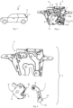
- FIG 1 a motor vehicle 1 in the form of a car is shown as an example, which in the example has a flap or tailgate 2 that can be closed and opened via a lock arrangement 3.
- the Figure 2 shows a perspective view of the Figure 1 merely exemplary lock arrangement 3, whereas in Figure 3 the lock arrangement is shown in a single part view.
- Figures 4 to 11 For reasons of clarity, a representation of a Figures 2 and 3 visible lock housing 4.
- the Figures 2 and 3 show the lock arrangement 3, in which a locking bolt (not shown in detail in the figures and arranged in a fixed position on the motor vehicle 1) interacts with a rotary latch mouth 5 of a rotary latch 6, wherein in the closed position of the lock arrangement 3 the locking bolt is caught in the rotary latch mouth 5 of the rotary latch 5 and the rotary latch 5 is in engagement with a pawl 7 so that the tailgate 2 is locked, whereas the tailgate 2 can be swung open when the rotary latch 5 and the pawl 7 are disengaged and the locking bolt can move out of the rotary latch mouth 5.
- a reverse arrangement is also conceivable, in which the lock arrangement 3 is fixed in a fixed position on the motor vehicle 1 and the locking bolt can move with the tailgate 2.
- the lock arrangement 3 comprises the rotary latch 6, which is mounted on the lock housing 4 so as to be rotatable about a rotation axis 8 (see Figure 2 ).
- the rotary latch 6 is arranged in a locking position, which is a position for locking the vehicle flap 2.
- the rotary latch 6 is spring-loaded in the direction of its open position. This means that, for example, a spring exerts a force on the rotary latch 6 to push the rotary latch 6 into the open position when the rotary latch 6 is arranged in the locking position.
- the pawl 7 holds the rotary latch 6 in its locking position when the pawl 7 is arranged in a locking position (see Figure 2 ).
- the pawl 7 is pivotably mounted on the lock housing 4 via a pivot axis 9 and can be moved between the locking position, in which the pawl 7 secures the rotary latch 6 in its locking position, and a release position that releases the rotary latch 6.
- the pivot axis 9 itself is pivotably mounted on the lock housing 4 by means of a movement element 10 is movably attached to the lock housing 4.
- a merely Figure 2 shown spring element 11 on the pawl 7 and pushes a free longitudinal end 14 of the pawl 7, which is designed as a hook-shaped pawl section 12, in the direction of the rotary latch 6.
- the spring element 11 thus ensures that the pawl 7 is spring-loaded from its release position towards its locking position with the aid of the spring element 11.
- a first leg 11a of the spring element 11 is supported on the lock housing 4, whereas a second leg 11b of the spring element 11 rests on a pawl pin 7a of the pawl and exerts a force on the pawl 6 acting in the direction of the rotary latch 7 via the pawl pin 7a.
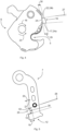
- the hook-shaped latch section 12 has a first locking surface 15. Furthermore, a radially protruding locking element 16 (see Figure 2 ) which has a first contact surface 17.
- the first locking surface 15 enables the pawl 7, when arranged in the locking position, to rotate the rotary latch 6 in the direction of the open position (see arrow 18 in Figure 4 ) is designed to block, in that in the blocking position the pawl 7 with its pawl section 12 engages under the locking element 16 on the first contact surface 17 and the pawl 7 with the first blocking surface 15 rests at least partially on the first contact surface 17 in such a way that a rotational movement of the rotary latch 6 in the direction of the open position is blocked.
- the first blocking surface 15 and the first contact surface 17 are not in complete contact with each other in the blocking position or the locking position. Rather, the first blocking surface 15 rests at least partially on the first contact surface 17, as is the case for various states in the Figures 6 to 8 is shown, whereby also states are conceivable in which the first contact surface 17 rests completely against the first blocking surface 15.
- the first locking surface 15 of the pawl 7 is designed with a greater length 19 than the length 29 of the first contact surface 17 of the rotary latch 6.
- the length 19 of the first locking surface 15 is designed to be greater than the length 20 of the second locking surface 21 (see Figure 5 ).
- the length 29 of the first contact surface 17 is larger than the length 30 of the second contact surface 22 (see Figure 4 ).
- the pawl 7 in the locking position causes a rotational movement of the rotary latch 6 in a direction opposite to the open position (see arrow 23 in Figure 4 ) is designed to block.
- the locking pawl 7 has a second locking surface 21 spaced from the first locking surface 15, whereas the rotary latch 6 has a second bearing surface 22 spaced from the first contact surface 17.
- the locking pawl 7 rests with the second locking surface 21 on the second contact surface 22 at least in sections in such a way that a rotational movement of the rotary latch 6 in the direction 23 opposite to the open position is blocked.
- the locking element 16 of the rotary latch 6 is designed as a tooth-shaped projection 24 that protrudes radially from the rotary latch 6.
- the pawl section 12 of the locking pawl 7 has, in the first embodiment, a mouth-shaped recess 25 that is matched to the tooth-shaped projection 24 of the rotary latch 6.
- the tooth-shaped projection 24 of the rotary latch 6 is dimensioned such that when the locking pawl 7 moves from the release position to the locking position, the mouth-shaped recess 25 receives and surrounds the tooth-shaped projection 24 of the rotary latch 6 at least in sections without friction and without contact, and that when the locking pawl 7 moves from the locking position to the In the release position, the pawl 7 and the rotary latch 7 can easily be released from one another and disengaged.
- the tooth-shaped projection 24 of the rotary latch 6 is arranged at least partially within the mouth-shaped recess 25 of the pawl 7.
- first contact surface 17 and the second contact surface 2 of the rotary latch 6 form side flanks 24a and 24b of the tooth-shaped projection 24 facing away from one another.
- first blocking surface 15 and the second blocking surface 21 are aligned facing an interior 26 of the mouth-shaped recess 25 and are arranged opposite one another and facing one another, as shown in Figure 5 is shown.
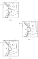
- a jamming occurs between the tooth-shaped projection 24 of the rotary latch 6 and the mouth-shaped recess 25 of the pawl 7 when the pawl 7 is arranged in its locking position and the projection 24 is arranged at least partially in the recess 25.
- a minimal movement of the rotary latch 6, which is less than the movement tolerance given by the elastic flap seal leads to a wedging of the tooth-shaped projection 24 in the mouth-shaped recess 25, as is shown in the Figures 6 to 8 for different relative positions of the rotary latch 6 to the locking pawl 7.
- the clamping or wedging of the projection 24 and the recess 25, but also the release of this clamping to release the tailgate 2, is facilitated by the fact that the first contact surface 17 and the second contact surface 22 are arranged in the direction of the locking pawl 7 at a contact surface angle 27 between 5° and 15° diverging from one another (see Figure 4 ).
- the contact surface angle 27 is preferably 10°.
- Jamming or wedging of the projection 24 and the recess 25 is further promoted if the first locking surface 15 and the second locking surface 21 are in a direction away from the rotary latch 6.
- Direction are arranged diverging from one another at a blocking surface angle 28.
- the blocking surface angle 28 is smaller than the contact surface angle 27.
- the respective dashed line which marks the course of the first blocking surface 15 or the first contact surface 17 has been shifted parallel to the dashed line which marks the course of the second blocking surface 21 or the second contact surface 22.
- first locking surface 15 in the locking position is arranged parallel to the first contact surface 17, wherein the first locking surface 15 and the second locking surface 21 are designed to diverge in the direction of the rotary latch 6.
- first locking surface 15 in the locking position is arranged parallel to the first contact surface 17, wherein the distance 50 between the first locking surface 15 and the second locking surface 21 increases in the direction of the rotary latch 6.
- the hooking which can also be referred to as jamming or wedging, is for the Figures 6 to 8 shown states characterized in that in the locking position both the first locking surface 15 rests at least partially on the first contact surface 17 and the second locking surface 21 rests at least partially on the second contact surface 22 so that both a rotary movement of the rotary latch 6 in the direction of the open position 18 is blocked and a rotary movement of the rotary latch 6 in the direction opposite to the open position 23 is blocked.
- the described wedge effect or wedge interlock ensures that the rotary latch 6 cannot rotate at all about the axis of rotation 8 when the rotary latch 6 is in the locked position and the pawl 7 is in the locked position.
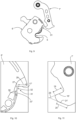
- the Figures 9 to 11 show a second embodiment of the present invention.
- the second embodiment differs from the first embodiment by an alternative design of the rotary latch 6' and the pawl 7', which will be discussed below.
- the first contact surface 17' of the rotary latch 6' is designed opposite the second contact surface 22'.
- the rotary latch 6' has a contact recess 31 which is designed adjacent to the first contact surface 17'.
- the second contact surface 22' forms at least one wall section of the contact recess 31, such as in particular the Figure 10 can be seen.
- the first blocking surface 15' is arranged facing away from the second blocking surface 21'.
- the first blocking surface 15' and the second blocking surface 21' are arranged in a direction away from the rotary latch 7', diverging from one another at the blocking surface angle 28. Furthermore, the first contact surface 17' and the second contact surface 22' are arranged diverging from one another in the direction of the locking pawl 7' at a contact surface angle 27 which is between 75° and 85°, the contact surface angle 27 being greater than the blocking surface angle 28.
- the first blocking surface 15' has a smaller length 19 than the second blocking surface 21', although this is not absolutely necessary, because the second blocking surface 21' only has to have a length with which it can at least partially be attached to the second contact surface 22'.
- the first blocking surface 15' can alternatively also have a greater length 19 than the second blocking surface 21'.
- the first contact surface 17' also has a greater length 29 than the second contact surface 22'.
- the contact recess 31 also has a contact contour 32 that is coordinated with the hook-shaped latch section 12. This coordination means that in the locking position, the first locking surface 15' rests at least partially on the first contact surface 17' and the second locking surface 21' rests at least partially on the second contact surface 22', so that a rotational movement of the rotary latch 6' is blocked both in the direction of the open position and in a direction opposite to the open position.
- the locking surface angle 28 is smaller than the contact surface angle 27, as in the first embodiment, as can be seen from the Figures 10 and 11 can be seen.
- the functioning of the second embodiment is identical and takes place according to the identical clamping principle, in that in the locking position the first locking surface 15' rests at least partially on the first contact surface 17' and the second locking surface 21' rests at least partially on the second contact surface 22', so that with regard to the principle according to the invention reference is made to the explanations for the first embodiment.
- the invention is directed to a lock arrangement 3 for a vehicle flap 2.
- the lock arrangement comprises the lock housing 4, the rotary latch 6 rotatably mounted on the lock housing 4 and the pawl 7 pivotably mounted on the lock housing 4.
- the pawl 7 has the mouth-shaped recess 25, which in the locking position at least partially receives the tooth-shaped projection 24 of the rotary latch 6 in such a way that both the first locking surface 15 at least partially on the first Contact surface 17 and the second blocking surface 21 at least partially rests on the second contact surface 22.
Landscapes
- Lock And Its Accessories (AREA)
Description
- Die Erfindung betrifft eine Schlossanordnung, insbesondere für Fahrzeugtüren oder Fahrzeugklappen, mit einem Schlossgehäuse, einer an dem Schlossgehäuse drehbar gelagerten Drehfalle, die in eine Raststellung zur Verriegelung der Fahrzeugtür oder Fahrzeugklappe und eine Offenstellung zur Freigabe der Fahrzeugtür oder Fahrzeugklappe bewegbar ist, und einer an dem Schlossgehäuse schwenkbar gelagerten Sperrklinke, die zwischen einer die Drehfalle in ihrer Raststellung sichernden Sperrstellung und einer die Drehfalle freigebenden Freigabestellung bewegbar ist, wobei die Sperrklinke in der Sperrstellung eine Drehbewegung der Drehfalle in Richtung der Offenstellung blockierend ausgebildet ist, und wobei die Sperrklinke in der Sperrstellung eine Drehbewegung der Drehfalle in eine der Offenstellung entgegengesetzte Richtung blockierend ausgebildet ist.
- Aus dem Dokument
EP 3 362 975 ist eine Schließvorrichtung bekannt, welche ein als Drehfalle vergleichbares und drehbar gelagertes Schnappschloss mit einer Aufnahme für einen Schließbolzen und eine mit einer Sperrklinke vergleichbare Blockierungsklinke aufweist, die ebenfalls drehbar gelagert ist und die das Schnappschloss verriegelt hält, wenn das Schnappschloss in einer Schließposition angeordnet ist, in welcher das Schnappschloss den Schließbolzen festhält. An der Blockierungsklinke sind eine erste Sperrfläche und eine zweite Sperrfläche ausgebildet, die in einer von der Blockierungsklinke wegweisenden Richtung auseinanderlaufend angeordnet sind. - Eine Schlossanordnung der eingangs bezeichneten Art ist beispielsweise aus der
US 2015/376919 A1 , derJP 2004 238841 A JP 2005 161987 A DE 10 2012 102 724 A1 bekannt ist, welche eine Drehfalle und eine die Drehfalle in einer Raststellung haltende Sperrklinke aufweist, wobei die Drehfalle und die Sperrklinke an einem Schlossgehäuse drehbar gelagert sind. Beim Schließvorgang sorgt ein in das Maul der Drehfalle einfallender Schließbolzen dafür, dass die Drehfalle aus ihrer Offenstellung in ihre Raststellung gedreht wird, wobei bei dieser Drehbewegung die Drehfalle mit der Sperrklinke in Eingriff gelangt. In der Raststellung der Drehfalle ist dann eine Bewegung der Drehfalle in ihre Offenstellung erst dann wieder möglich, wenn die Sperrklinke aus ihrer Sperrstellung in ihre Freigabestellung bewegt wird, was mit Hilfe eines dafür vorgesehenen Antriebselements realisiert wird. In der Raststellung der Drehfalle kann sich aber die Drehfalle in eine über die Raststellung hinausgehende Überhubstellung drehen, wodurch ein Spiel zu der Sperrklinke erzeugt wird und sich die Drehfalle relativ zu dem Schließbolzen bewegen kann, was ein für den Benutzer wahrnehmbares Klappergeräusch bewirkt. Insbesondere bei Schlossanordnungen, die bei flach eingebauten Heckklappen verwendet werden, sind die Dichtungskräfte gering, wodurch nur eine sehr geringe bis gar keine Spannung auf die Schlossanordnung von Drehfalle und Sperrklinke wirkt, wodurch es der Drehfalle möglich ist, in die vorstehend beschriebene Überhubstellung zu drehen, was zu dem beschriebenen sowie unerwünschten Klappergeräusch führt. Aus diesem Grund ist bei der aus derDE 10 2012 102 724 A1 bekannten Schlossanordnung eine Lösung bekannt, bei der ein drehbar an dem Schlossgehäuse gelagertes Ruhigstellungselement vorgesehen ist, welches dafür sorgt, dass in Raststellung der Drehfalle der Schließbolzen zwischen der Drehfalle und dem hebelförmigen Ruhigstellungselement eingeklemmt wird, so dass eine relative Bewegung des Schließbolzens in Bezug auf die Drehfalle, was für das störende Klappergeräusch ursächlich ist, unterbunden wird. Nachteilig bei dieser bekannten Schlossanordnung ist es, dass zur Ruhigstellung ein zusätzliches Bauteil benötigt wird, was sich in höheren Herstellungskosten und in einer verringerten Kompaktheit der Schlossanordnung niederschlägt. - Der Erfindung liegt die Aufgabe zugrunde, auf konstruktiv einfache Weise und kostengünstig eine Schlossanordnung zu entwickeln, bei welcher eine unerwünschte Geräuschentwicklung vermieden wird und die sich durch eine kompakte Bauform auszeichnet.
- Bei einer Schlossanordnung der eingangs bezeichneten Art wird diese Aufgabe erfindungsgemäß dadurch gelöst, dass an einem Längsende der Sperrklinke ein hakenförmig ausgebildeter Klinkenabschnitt ausgebildet ist, der eine erste Sperrfläche aufweist, und dass die Drehfalle ein radial abstehendes Rastelement mit einer ersten Anlagefläche aufweist, wobei in Sperrstellung die Sperrklinke mit ihrem Klinkenabschnitt das Rastelement an der ersten Anlagefläche untergreift und die Sperrklinke mit der ersten Sperrfläche an der ersten Anlagefläche zumindest abschnittsweise derart anliegt, dass eine Drehbewegung der Drehfalle in Richtung der Offenstellung blockiert ist, wobei die Sperrklinke eine von der ersten Sperrfläche beabstandete zweite Sperrfläche aufweist, wobei die Drehfalle eine von der ersten Anlagefläche beabstandete zweite Anlagefläche aufweist, und wobei in Sperrstellung die Sperrklinke mit der zweiten Sperrfläche an der zweiten Anlagefläche zumindest abschnittsweise derart anliegt, dass eine Drehbewegung der Drehfalle in eine der Offenstellung entgegengesetzte Richtung blockiert ist, und wobei die erste Sperrfläche und die zweite Sperrfläche in einer von der Drehfalle wegweisenden Richtung unter einem Sperrflächen-Winkel auseinanderlaufend zueinander angeordnet sind. Die Sperrklinke blockiert somit eine Drehbewegung der Drehfalle sowohl in Drehrichtung ihrer Offenstellung als auch in eine der Offenstellung entgegengesetzte Drehrichtung. Folglich ist eine Drehbewegung der Drehfalle in beide Drehrichtungen allein durch die Sperrklinke blockiert.
- Vorteilhafte und zweckmäßige Ausgestaltungen und Weiterbildungen der Erfindung ergeben sich aus den Unteransprüchen.
- Durch die Erfindung wird auf konstruktiv einfache Weise und kostengünstig eine Schlossanordnung bereitgestellt, welche sich durch einen einfachen sowie kompakten Aufbau auszeichnet und dennoch wirksam eine Drehbewegung der Drehfalle aus ihrer Raststellung heraus in beide Drehrichtungen verhindert, wenn die Sperrklinke in ihrer Sperrstellung angeordnet ist. Dadurch, dass die Sperrklinke eine Drehbewegung der Drehfalle in eine über die Raststellung hinausgehende Überhubstellung zu einem Zeitpunkt unterbindet, ab dem die Sperrklinke in ihrer Sperrstellung angeordnet ist, wird das aus dem Stand der Technik bekannte Problem des unerwünschten Klappergeräusches wirksam vermieden. Die Erfindung zeichnet sich durch eine rein mechanische Lösung aus, die im Unterschied zu bekannten Schlossanordnungen aus dem Stand der Technik ohne ein zusätzliches Bauteil, wie zum Beispiel ein hebelförmiges Ruhigstellungselement, und ohne etwaige gummiartige und verschleißanfällige Pufferelemente auskommt.
- Gemäß einer ersten Ausführungsform der Erfindung ist es von besonderem Vorteil, wenn das Rastelement der Drehfalle als ein radial von der Drehfalle abstehender und zahnförmiger Ansatz ausgebildet ist und dass der Klinkenabschnitt der Sperrklinke eine maulförmige und auf den zahnförmigen Ansatz der Drehfalle abgestimmte Ausnehmung aufweist, wobei in Sperrstellung der zahnförmige Ansatz der Drehfalle zumindest abschnittsweise innerhalb der maulförmigen Ausnehmung der Sperrklinke liegend angeordnet ist. Der maulförmige Klinkenabschnitt der Sperrklinke und der zahnförmige Ansatz der Drehfalle gehen in Sperrstellung der Sperrklinke sowie in Raststellung der Drehfalle eine formschlüssige Verbindung ein, durch die sowohl eine Bewegung der Drehfalle in ihre Offenstellung als auch in eine der Offenstellung entgegengesetzte Richtung blockiert ist. Dabei ist die maulförmige Ausnehmung auf den zahnförmigen Ansatz derart abgestimmt, dass die Funktionsfähigkeit sowohl für die in Sperrstellung erwünschte Keilwirkung als auch für ein leichtes Lösen von Drehfalle und Sperrklinke bei Öffnung der Fahrzeugklappe gewährleistet ist.
- Konstruktiv besonders günstig ist es bei Ausgestaltung der ersten Ausführungsform, wenn die erste Anlagefläche und die zweite Anlagefläche der Drehfalle voneinander abgewandte Seitenflanken des zahnförmigen Ansatzes sind. Entsprechend sind die erste Sperrfläche und die zweite Sperrfläche einem Innenraum der maulförmigen Ausnehmung zugewandt ausgerichtet und einander gegenüberliegend sowie einander zugewandt angeordnet. Die Drehfalle sowie die Sperrklinke weisen somit eine konstruktiv einfache Form auf, die mit Hilfe bekannter Herstellungsverfahren kostengünstig hergestellt werden können.
- Der zahnförmige Ansatz und die maulförmige Ausnehmung sind derart aufeinander abgestimmt, dass in Sperrstellung zwischen dem zahnförmigen Ansatz und der maulförmigen Ausnehmung eine Keilverhakung auftritt. Dadurch verkeilen während der Fahrt eines Kraftfahrzeugs die Sperrklinke und die Drehfalle miteinander, wodurch Klappergeräusche verhindert werden. Hinsichtlich der Keilwirkung bzw. Keilverhakung ist es in Ausgestaltung für die erste Ausführungsform besonders günstig, wenn die erste Anlagefläche und die zweite Anlagefläche in Richtung der Sperrklinke unter einem Anlageflächen-Winkel zwischen 5° und 15° auseinanderlaufend zueinander angeordnet sind. Eine Ausgestaltung für eine zweite Ausführungsform sieht vor, dass die erste Anlagefläche der zweiten Anlagefläche gegenüberliegend ausgebildet ist, wobei die Drehfalle eine Anlageausnehmung aufweist, die an die erste Anlagefläche angrenzend angeordnet und ausgebildet ist, wobei die zweite Anlagefläche wenigstens einen Wandabschnitt der Anlageausnehmung bildet.
- Für die zweite Ausführungsform ist in weiterer Ausgestaltung vorgesehen, dass die Anlageausnehmung eine mit dem hakenförmig ausgebildeten Klinkenabschnitt abgestimmte Anlagekontur aufweist, so dass in Sperrstellung zumindest abschnittsweise die erste Sperrfläche an der ersten Anlagefläche und zumindest abschnittsweise die zweite Sperrfläche an der zweiten Anlagefläche derart anliegen, dass eine Drehbewegung der Drehfalle in Richtung der Offenstellung und in eine der Offenstellung entgegengesetzte Richtung, also einer Überhubstellung, blockiert sind.
- In Bezug auf eine ausreichende Keilwirkung ist es in Ausgestaltung der zweiten Ausführungsform von Vorteil, wenn die erste Anlagefläche und die zweite Anlagefläche in Richtung der Sperrklinke unter einem Anlageflächen-Winkel zwischen 75° und 85° auseinanderlaufend zueinander angeordnet sind.
- Für die erste Ausführungsform und für die zweite Ausführungsform ist es im Hinblick auf die Funktionsfähigkeit (Keilwirkung, aber auch ein leichtes Lösen von Drehfalle und Sperrklinke bei Öffnung der Fahrzeugklappe) besonders günstig, wenn die erste Sperrfläche eine größere Länge als die zweite Sperrfläche aufweist. Dadurch ist gewährleistet, dass in Sperrstellung die Keilwirkung vorhanden ist und dass sich Drehfalle und Sperrklinke leicht lösen, wenn die Drehfalle in ihre Offenstellung gelangen soll. Ebenso günstig auf die Funktionssicherheit wirkt es sich in Ausgestaltung beider Ausführungsformen aus, wenn die erste Anlagefläche eine größere Länge als die zweite Anlagefläche aufweist.
- Für beide Ausführungsformen ist es hinsichtlich der Funktionsfähigkeit ferner vorteilhaft, wenn die erste Anlagefläche und die zweite Anlagefläche in Richtung der Sperrklinke unter einem Anlageflächen-Winkel auseinanderlaufend zueinander angeordnet sind. Mit Bezug auf die Sperrklinke ist es ebenso von Vorteil, wenn die erste Sperrfläche und die zweite Sperrfläche in einer von der Drehfalle wegweisenden Richtung unter einem Sperrflächen-Winkel auseinanderlaufend zueinander angeordnet sind.
- Damit in Sperrstellung eine ausreichende Reibung vorhanden ist, damit sich die Verkeilung von Sperrklinke und Drehfalle in der Sperrstellung nicht löst und dennoch für einen Öffnungsvorgang der Heckklappe ein Lösen der Verkeilung möglich ist, sieht eine Ausgestaltung vor, dass in Sperrstellung die erste Sperrfläche parallel zu der ersten Anlagefläche angeordnet ist, wobei die erste Sperrfläche und die zweite Sperrfläche in Richtung der Drehfalle auseinanderlaufend ausgestaltet sind. Ebenso ist es hierbei von Vorteil, wenn in Sperrstellung die erste Sperrfläche parallel zu der ersten Anlagefläche angeordnet ist, wobei der Abstand zwischen der ersten Sperrfläche und der zweiten Sperrfläche in Richtung der Drehfalle zunimmt.
- Gemäß einer alternativen Ausgestaltung ist es denkbar, dass die erste Sperrfläche nicht parallel zur ersten Anlagefläche gestaltet ist, sondern dass es sich bei zumindest einer der Flächen (Sperrfläche(n) und/oder Anlagefläche(n)) um im Radius gestaltete Flächen handelt, bei denen die Radien der Flächen (Sperrfläche(n) und/oder Anlagefläche(n)) zwar denselben Radius aufweisen, die Radienmittelpunkte aber versetzt zueinander liegend sind, so dass es nur zu einer Linienberührung von Sperrfläche und Anlagefläche kommt. Mit Hilfe einer solchen Ausgestaltung können die Reibungsverhältnisse zwischen Sperrfläche und Anlagefläche eingestellt werden. Der Versatz der Radienmittelpunkte bewirkt zudem, dass die Sperrklinke durch die Drehfalle, die in die Öffnungsstellung drängt, immer in die Sperrstellung gezogen wird.
- Um die Drehfalle aus ihrer Raststellung in die Offenstellung zu drehen, ist in Ausgestaltung vorgesehen, dass die Drehfalle in Richtung ihrer Offenstellung federvorgespannt ist. Auf diese Weise kann auf einen motorischen Antrieb zur Bewegung der Drehfalle verzichtet werden.
- Schließleich sieht eine weitere Ausgestaltung vor, dass die Sperrklinke in Richtung ihrer Sperrstellung mit Hilfe eines Federelements federbeaufschlagt ist. Das Federelement drängt somit in Sperrstellung den hakenförmig ausgebildeten Klinkenabschnitt der Sperrklinke immer in Richtung der Drehfalle, so dass die Klemmwirkung zwischen dem Klinkenabschnitt der Sperrklinke und der Drehfalle durch das Federelement unterstützt wird. Dabei stützt sich ein Schenkel des Federelements an dem Schlossgehäuse ab, wohingegen der andere Schenkel des Federelements beispielsweise an einem Sperrklinkenansatz der Sperrklinke anliegt.
- Es versteht sich, dass die vorstehend genannten und nachstehend noch zu erläuternden Merkmale nicht nur in der jeweils angegebenen Kombination, sondern auch in anderen Kombinationen verwendbar sind, ohne den Rahmen der vorliegenden Erfindung zu verlassen. Der Rahmen der Erfindung ist nur durch die Ansprüche definiert.
- Weitere Einzelheiten, Merkmale und Vorteile des Gegenstandes der Erfindung ergeben sich aus der nachfolgenden Beschreibung im Zusammenhang mit der Zeichnung, in der beispielhafte bevorzugte Ausführungsformen der Erfindung dargestellt sind. In der Zeichnung zeigt:
-
Figur 1 eine Seitenansicht eines Kraftfahrzeugs mit einer Schlossanordnung gemäß der Erfindung, -
Figur 2 eine Perspektivansicht auf die Schlossanordnung gemäß einer ersten Ausführungsform der Erfindung, -
Figur 3 eine Einzelteildarstellung der Schlossanordnung gemäß der ersten Ausführungsform der Erfindung, -
Figur 4 eine Ansicht auf eine Drehfalle gemäß der ersten Ausführungsform der Erfindung, -
Figur 5 eine Ansicht auf eine Sperrklinke gemäß der ersten Ausführungsform der Erfindung, -
Figur 6 eine vergrößerte Ansicht auf die Drehfalle und die mit der Drehfalle in Eingriff stehende Sperrklinke gemäß der ersten Ausführungsform der Erfindung, -
Figur 7 eine weitere vergrößerte Ansicht auf die Drehfalle und die mit der Drehfalle in Eingriff stehende Sperrklinke gemäß der ersten Ausführungsform der Erfindung, -
Figur 8 eine noch weitere vergrößerte Ansicht auf die Drehfalle und die mit der Drehfalle in Eingriff stehende Sperrklinke gemäß der ersten Ausführungsform der Erfindung, -
Figur 9 eine Ansicht auf eine Drehfalle und eine Sperrklinke gemäß einer zweiten Ausführungsform der Erfindung, -
Figur 10 eine vergrößerte Detailansicht der Drehfalle aus derFigur 9 und -
Figur 11 eine vergrößerte Detailansicht der Sperrklinke aus derFigur 10 . - In
Figur 1 ist ein Kraftfahrzeug 1 in Form eines PKWs exemplarisch dargestellt, welches in dem Beispiel über eine Klappe bzw. Heckklappe 2 verfügt, die über eine Schlossanordnung 3 verschließbar ist und geöffnet werden kann. DieFigur 2 zeigt dabei eine perspektivische Ansicht auf die inFigur 1 lediglich exemplarisch angedeutete Schlossanordnung 3, wohingegen inFigur 3 die Schlossanordnung in einer Einzelteildarstellung gezeigt ist. In denFiguren 4 bis 11 wurde aus Gründen der Übersichtlichkeit auf eine Darstellung eines aus denFiguren 2 und 3 ersichtlichen Schlossgehäuses 4 verzichtet. - In den
Figuren 2 bis 8 ist eine erste Ausführungsform der Erfindung dargestellt, wohingegen in denFiguren 9 bis 11 eine zweite Ausführungsform gezeigt ist. Die nachstehende Beschreibung besitzt für beide Ausführungsformen Gültigkeit, auch wenn nur die erste Ausführungsform für bestimmte Bauteile eine detaillierte Beschreibung liefert. Auf die speziellen Unterschiede zwischen den beiden Ausführungsformen wird explizit hingewiesen werden. - Die
Figuren 2 und 3 zeigen die Schlossanordnung 3, bei der ein in den Figuren nicht näher dargestellter und ortsfest am Kraftfahrzeug 1 angeordneter Schließbolzen mit einem Drehfallenmaul 5 einer Drehfalle 6 zusammenwirkt, wobei in Schließstellung der Schlossanordnung 3 der Schließbolzen in dem Drehfallenmaul 5 der Drehfalle 5 gefangen ist und die Drehfalle 5 mit einer Sperrklinke 7 in Eingriff steht, so dass die Heckklappe 2 verriegelt ist, wohingegen die Heckklappe 2 aufgeschwenkt werden kann, wenn die Drehfalle 5 und die Sperrklinke 7 außer Eingriff stehen und der Schließbolzen sich aus dem Drehfallenmaul 5 heraus bewegen kann. Selbstverständlich ist auch eine umgekehrte Anordnung denkbar, bei welcher die Schlossanordnung 3 ortsfest am Kraftfahrzeug 1 festgelegt ist und der Schließbolzen mit der Heckklappe 2 mitbewegbar ist. - Folglich umfasst die erfindungsgemäße Schlossanordnung 3 die Drehfalle 6, die um eine Drehachse 8 drehbar an dem Schlossgehäuse 4 gelagert ist (siehe
Figur 2 ). InFigur 2 ist die Drehfalle 6 in einer Raststellung angeordnet, welches eine Stellung zur Verriegelung der Fahrzeugklappe 2 ist. Bei Drehung um die Drehachse 8 im Uhrzeigersinn kann die Drehfalle 6 in eine Offenstellung bewegt werden, um den Schließbolzen und damit die Fahrzeugklappe 2 freizugeben. Die Drehfalle 6 ist in Richtung ihrer Offenstellung federvorgespannt. Dies bedeutet, dass zum Beispiel eine Feder eine Kraft auf die Drehfalle 6 ausübt, um die Drehfalle 6 in die Offenstellung zu drängen, wenn die Drehfalle 6 in der Raststellung angeordnet ist. Dabei hält die Sperrklinke 7 die Drehfalle 6 in ihrer Raststellung, wenn die Sperrklinke 7 in einer Sperrstellung angeordnet ist (sieheFigur 2 ). Die Sperrklinke 7 ist über eine Schwenkachse 9 schwenkbar an dem Schlossgehäuse 4 gelagert und zwischen der Sperrstellung, in welcher die Sperrklinke 7 die Drehfalle 6 in ihrer Raststellung sichert, und einer die Drehfalle 6 freigebenden Freigabestellung bewegbar. Die Schwenkachse 9 selbst ist mit Hilfe eines schwenkbar an dem Schlossgehäuse 4 gelagerten Bewegungselements 10 bewegbar an dem Schlossgehäuse 4 angebracht. Zumindest dann, wenn die Sperrklinke 7 ihre Sperrstellung einnehmen soll, wirkt ein lediglich inFigur 2 gezeigtes Federelement 11 auf die Sperrklinke 7 ein und drängt ein freies Längsende 14 der Sperrklinke 7, welches als ein hakenförmig ausgebildeter Klinkenabschnitt 12 ausgebildet ist, in Richtung der Drehfalle 6. Das Federelement 11 sorgt somit dafür, dass die Sperrklinke 7 aus ihrer Freigabestellung in Richtung ihrer Sperrstellung mit Hilfe des Federelements 11 federbeaufschlagt ist. Ein erste Schenkel 11a des Federelements 11 stützt sich dabei an dem Schlossgehäuse 4 ab, wohingegen ein zweiter Schenkel 11b des Federelements 11 an einem Sperrklinkenzapfen 7a der Sperrklinke anliegt und über den Sperrklinkenzapfen 7a eine in Richtung der Drehfalle 7 wirkende Kraft auf die Sperrklinke 6 ausübt. - Der hakenförmig ausgebildete Klinkenabschnitt 12 weist eine erste Sperrfläche 15 auf. Ferner ist an der Drehfalle 6 ein radial abstehendes Rastelement 16 (siehe
Figur 2 ) ausgebildet, welches eine erste Anlagefläche 17 aufweist. Durch die erste Sperrfläche 15 ist die Sperrklinke 7, wenn sie in der Sperrstellung angeordnet ist, eine Drehbewegung der Drehfalle 6 in Richtung der Offenstellung (siehe Pfeil 18 inFigur 4 ) blockierend ausgebildet, indem in Sperrstellung die Sperrklinke 7 mit ihrem Klinkenabschnitt 12 das Rastelement 16 an der ersten Anlagefläche 17 untergreift und die Sperrklinke 7 mit der ersten Sperrfläche 15 an der ersten Anlagefläche 17 zumindest abschnittsweise derart anliegt, dass eine Drehbewegung der Drehfalle 6 in Richtung der Offenstellung blockiert ist. Die erste Sperrfläche 15 und die erste Anlagefläche 17 stehen in Sperrstellung bzw. Raststellung nicht vollständig miteinander in Kontakt. Vielmehr liegt die erste Sperrfläche 15 zumindest abschnittweise an der ersten Anlagefläche 17 an, wie es für verschiedene Zustände in denFiguren 6 bis 8 gezeigt ist, wobei auch Zustände denkbar sind, in denen die erste Anlagefläche 17 vollständig an der ersten Sperrfläche 15 anliegt. Wie aus den Figuren ersichtlich ist, ist die erste Sperrfläche 15 der Sperrklinke 7 mit einer größeren Länge 19 ausgebildet als die Länge 29 der ersten Anlagefläche 17 der Drehfalle 6. Ferner ist die Länge 19 der ersten Sperrfläche 15 größer ausgebildet als die Länge 20 der zweiten Sperrfläche 21 (sieheFigur 5 ). Schließlich ist die Länge 29 der ersten Anlagefläche 17 größer ausgebildet als die Länge 30 der zweiten Anlagefläche 22 (sieheFigur 4 ). - Charakteristisch für beide Ausführungsformen ist es, dass die Sperrklinke 7 in der Sperrstellung eine Drehbewegung der Drehfalle 6 in eine der Offenstellung entgegengesetzte Richtung (siehe Pfeil 23 in
Figur 4 ) blockierend ausgebildet ist. Hierzu weist die Sperrklinke 7 eine von der ersten Sperrfläche 15 beabstandete zweite Sperrfläche 21 auf, wohingegen die Drehfalle 6 eine von der ersten Anlagefläche 17 beabstandete zweite Anlagefläche 22 aufweist. Dabei liegt in Sperrstellung die Sperrklinke 7 mit der zweiten Sperrfläche 21 derart an der zweiten Anlagefläche 22 zumindest abschnittsweise an, dass eine Drehbewegung der Drehfalle 6 in die der Offenstellung entgegengesetzte Richtung 23 blockiert ist. - Mit Bezug auf die erste Ausführungsform der Erfindung, die in den
Figuren 2 bis 8 dargestellt ist, ist das Rastelement 16 der Drehfalle 6 als ein radial von der Drehfalle 6 abstehender und zahnförmiger Ansatz 24 ausgebildet. Der Klinkenabschnitt 12 der Sperrklinke 7 weist bei der ersten Ausführungsform eine maulförmige Ausnehmung 25 auf, die auf den zahnförmigen Ansatz 24 der Drehfalle 6 abgestimmt ist. Dabei ist der zahnförmige Ansatz 24 der Drehfalle 6 derart dimensioniert, dass bei einer Bewegung der Sperrklinke 7 aus der Freigabestellung in die Sperrstellung die maulförmige Ausnehmung 25 reibungsfrei und berührungslos den zahnförmigen Ansatz 24 der Drehfalle 6 zumindest abschnittsweise aufnimmt und umgibt und dass bei einer Bewegung der Sperrklinke 7 aus der Sperrstellung in die Freigabestellung die Sperrklinke 7 und die Drehfalle 7 leicht voneinander lösen und außer Eingriff gelangen. In der Sperrstellung ist der zahnförmige Ansatz 24 der Drehfalle 6 zumindest abschnittsweise innerhalb der maulförmigen Ausnehmung 25 der Sperrklinke 7 liegend angeordnet. Wie ausFigur 4 ersichtlich ist, bilden die erste Anlagefläche 17 und die zweite Anlagefläche 2 der Drehfalle 6 voneinander abgewandte Seitenflanken 24a und 24b des zahnförmigen Ansatzes 24. Demgegenüber sind die erste Sperrfläche 15 und die zweite Sperrfläche 21 zu einem Innenraum 26 der maulförmigen Ausnehmung 25 gewandt ausgerichtet und einander gegenüberliegend sowie einander zugewandt angeordnet, wie es inFigur 5 gezeigt ist. - Es ist ferner vorgesehen, dass sich eine Verklemmung zwischen dem zahnförmigen Ansatz 24 der Drehfalle 6 und der maulförmigen Ausnehmung 25 der Sperrklinke 7 einstellt, wenn die Sperrklinke 7 in ihrer Sperrstellung angeordnet ist und der Ansatz 24 zumindest abschnittsweise in der Ausnehmung 25 liegend angeordnet ist. Denn dann führt eine minimale Bewegung der Drehfalle 6, die geringer ist als die durch die elastische Klappendichtung gegebene Bewegungstoleranz, zu einem Verkeilen des zahnförmigen Ansatzes 24 in der maulförmigen Ausnehmung 25, wie es in den
Figuren 6 bis 8 für unterschiedliche Relativstellungen von Drehfalle 6 zu Sperrklinke 7 gezeigt ist. Die Verklemmung bzw. Verkeilung von Ansatz 24 und Ausnehmung 25, aber auch das Lösen dieser Verklemmung zur Freigabe der Heckklappe 2, wird dadurch begünstigt, dass die erste Anlagefläche 17 und die zweite Anlagefläche 22 in Richtung der Sperrklinke 7 unter einem Anlageflächen-Winkel 27 zwischen 5° und 15° auseinanderlaufend zueinander angeordnet sind (sieheFigur 4 ). Der Anlageflächen-Winkel 27 beträgt vorzugsweise 10°. Eine Verklemmung bzw. eine Verkeilung von Ansatz 24 und Ausnehmung 25 wird ferner dadurch begünstigt, wenn die erste Sperrfläche 15 und die zweite Sperrfläche 21 in einer von der Drehfalle 6 wegweisenden Richtung unter einem Sperrflächen-Winkel 28 auseinanderlaufend zueinander angeordnet sind. Dabei ist der Sperrflächen-Winkel 28 kleiner als der Anlageflächen-Winkel 27 ausgebildet. Zur Veranschaulichung des Anlageflächen-Winkels 27 und des Sperrflächen-Winkels 28 wurde die jeweilige gestrichelte Linie, welche den Verlauf der ersten Sperrfläche 15 bzw. der ersten Anlagefläche 17 kennzeichnet, parallel zu der gestrichelten Linie verschoben, welche den Verlauf der zweiten Sperrfläche 21 bzw. der zweiten Anlagefläche 22 kennzeichnet. - Es ist ferner vorgesehen, dass in Sperrstellung die erste Sperrfläche 15 parallel zu der ersten Anlagefläche 17 angeordnet ist, wobei die erste Sperrfläche 15 und die zweite Sperrfläche 21 in Richtung der Drehfalle 6 auseinanderlaufend ausgestaltet sind. Dies bedeutet, dass in Sperrstellung die erste Sperrfläche 15 parallel zu der ersten Anlagefläche 17 angeordnet ist, wobei der Abstand 50 zwischen der ersten Sperrfläche 15 und der zweiten Sperrfläche 21 in Richtung der Drehfalle 6 zunimmt.
- In den
Figuren 6, 7 und 8 sind Zustände gezeigt, in welchen die Sperrklinke 7 in ihrer Sperrstellung angeordnet ist und die Drehfalle 6 sich in ihrer Raststellung befindet. Die vorstehend beschriebene Ausbildung des Klinkenabschnitts 12 der Sperrklinke 7 und des Rastelements 16 der Drehfalle 6 sorgen bei einer auf die Drehfalle 6 einwirkenden Kraft, welche durch die Heckklappe 2 auf den Schließbolzen auf die Drehfalle 6 übertragen wird dafür, dass sich der zahnförmige Ansatz 24 der Drehfalle 6 in der maulförmigen Ausnehmung 25 der Sperrklinke 7 derart verkeilt bzw. verhakt, dass während des Fahrtbetriebs des Kraftfahrzeugs 2 Klappergeräusche verhindert werden. Die Verhakung, die auch als Verklemmung oder Verkeilung bezeichnet werden kann, ist für die in denFiguren 6 bis 8 gezeigten Zustände dadurch gekennzeichnet, dass in Sperrstellung sowohl die erste Sperrfläche 15 zumindest abschnittsweise an der ersten Anlagefläche 17 anliegt als auch die zweite Sperrfläche 21 zumindest abschnittsweise an der zweiten Anlagefläche 22 anliegt, so dass sowohl eine Drehbewegung der Drehfalle 6 in die Richtung der Offenstellung 18 blockiert ist als auch eine Drehbewegung der Drehfalle 6 in die der Offenstellung entgegengesetzte Richtung 23 blockiert ist. Durch die beschriebene Keilwirkung bzw. Keilverhakung ist sichergestellt, dass sich die Drehfalle 6 in Raststellung der Drehfalle 6 und in Sperrstellung der Sperrklinke 7 überhaupt nicht um die Drehachse 8 drehen kann. - Die
Figuren 9 bis 11 zeigen eine zweite Ausführungsform der vorliegenden Erfindung. Die zweite Ausführungsform unterscheidet sich von der ersten Ausführungsform durch eine alternative Ausgestaltung von Drehfalle 6' und Sperrklinke 7', worauf nachstehend eingegangen wird. Bei der zweiten Ausführungsform ist bei der Drehfalle 6' die erste Anlagefläche 17' der zweiten Anlagefläche 22' gegenüberliegend ausgebildet. Die Drehfalle 6' weist dabei eine Anlageausnehmung 31 auf, die an die erste Anlagefläche 17' angrenzend ausgebildet ist. Ferner bildet die zweite Anlagefläche 22' wenigstens einen Wandabschnitt der Anlageausnehmung 31, wie insbesondere derFigur 10 zu entnehmen ist. Die erste Sperrfläche 15' ist von der zweiten Sperrfläche 21' abgewandt angeordnet. Dabei sind die erste Sperrfläche 15' und die zweite Sperrfläche 21' in einer von der Drehfalle 7' wegweisenden Richtung unter dem Sperrflächen-Winkel 28 auseinanderlaufend zueinander angeordnet. Ferner sind die erste Anlagefläche 17' und die zweite Anlagefläche 22' in Richtung der Sperrklinke 7' unter einem Anlageflächen-Winkel 27, der zwischen 75° und 85° beträgt, auseinanderlaufend zueinander angeordnet, wobei der Anlagenflächen-Winkel 27 größer ist als der Sperrflächen-Winkel 28. Im Unterschied zur ersten Ausführungsform weist bei der zweiten Ausführungsform die erste Sperrfläche 15' eine kleinere Länge 19 als die zweite Sperrfläche 21' auf, wobei dies nicht zwingend erforderlich ist, denn die zweite Sperrfläche 21' muss lediglich eine Länge aufweisen, mit welcher sie zumindest abschnittweise an der zweiten Anlagefläche 22' anliegen kann. Folglich kann die erste Sperrfläche 15' alternativ auch eine größere Länge 19 als die zweite Sperrfläche 21' aufweisen. Hingegen weist auch bei der zweiten Ausführungsform die erste Anlagefläche 17' eine größere Länge 29 als die zweite Anlagefläche 22' auf. Wie aus der Zusammenschau derFiguren 10 und 11 hervorgeht, weist ferner die Anlageausnehmung 31 eine mit der hakenförmig ausgebildeten Klinkenabschnitt 12 abgestimmte Anlagekontur 32 auf. Diese Abstimmung bewirkt, dass in Sperrstellung die erste Sperrfläche 15' zumindest abschnittsweise an der ersten Anlagefläche 17' und die zweite Sperrfläche 21' zumindest abschnittsweise an der zweiten Anlagefläche 22' anliegen, so dass eine Drehbewegung der Drehfalle 6' sowohl in Richtung der Offenstellung als auch in eine der Offenstellung entgegengesetzte Richtung blockiert ist. Bei der zweiten Ausführungsform ist der Sperrflächen-Winkel 28 wie bei der ersten Ausführungsform kleiner als der Anlageflächen-Winkel 27 ausgebildet, wie aus denFiguren 10 und 11 ersichtlich ist. Die Funktionsweise der zweiten Ausführungsform ist identisch und erfolgt nach dem identischen Verklemmungsprinzip, indem in Sperrstellung die erste Sperrfläche 15' zumindest abschnittweise an der ersten Anlagefläche 17' anliegt und die zweite Sperrfläche 21' zumindest abschnittsweise an der zweiten Anlagefläche 22' anliegt, so dass hinsichtlich des erfindungsgemäßen Prinzips auf die Ausführungen zur ersten Ausführungsform verwiesen wird. - Gemäß einer ersten Ausführungsform richtet sich die Erfindung auf eine Schlossanordnung 3 für eine Fahrzeugklappe 2. Die Schlossanordnung umfasst das Schlossgehäuse 4, die an dem Schlossgehäuse 4 drehbar gelagerte Drehfalle 6 und die an dem Schlossgehäuse 4 schwenkbar gelagerte Sperrklinke 7. Die Sperrklinke 7 weist die maulförmige Ausnehmung 25 auf, die in der Sperrstellung den zahnförmigen Ansatz 24 der Drehfalle 6 zumindest abschnittsweise derart aufnimmt, dass sowohl die erste Sperrfläche 15 zumindest abschnittsweise an der ersten Anlagefläche 17 anliegt als auch die zweite Sperrfläche 21 zumindest abschnittsweise an der zweiten Anlagefläche 22 anliegt. Das abschnittsweise Anliegen der Sperrflächen 15, 21 an den Anlageflächen 17, 22 stellt eine formschlüssige Verbindung zwischen der Sperrklinke 7 und der Drehfalle 6 her, so dass sowohl eine Drehbewegung der Drehfalle 6 in die Richtung der Offenstellung 18 blockiert ist als auch eine Drehbewegung der Drehfalle 6 in die der Offenstellung entgegengesetzte Richtung 23 blockiert ist.
- Die vorstehend beschriebene Erfindung ist selbstverständlich nicht auf die beschriebenen und dargestellten Ausführungsformen beschränkt. Es ist ersichtlich, dass an den in der Zeichnung dargestellten Ausführungsformen zahlreiche, dem Fachmann entsprechend der beabsichtigten Anwendung naheliegende Abänderungen vorgenommen werden können, solange der durch die anliegenden Ansprüche definierte Schutzbereich nicht verlassen wird.
Claims (13)
- Schlossanordnung (3), insbesondere für Fahrzeugtüren oder Fahrzeugklappen (2), mit einem Schlossgehäuse (4), einer an dem Schlossgehäuse (4) drehbar gelagerten Drehfalle (6; 6'), die in eine Raststellung zur Verriegelung der Fahrzeugtür oder Fahrzeugklappe (2) und eine Offenstellung zur Freigabe der Fahrzeugtür oder Fahrzeugklappe (2) bewegbar ist, und einer an dem Schlossgehäuse (4) schwenkbar gelagerten Sperrklinke (7; 7'), die zwischen einer die Drehfalle (6; 6') in ihrer Raststellung sichernden Sperrstellung und einer die Drehfalle (6; 6') freigebenden Freigabestellung bewegbar ist, wobei die Sperrklinke (7; 7') in der Sperrstellung eine Drehbewegung der Drehfalle (6; 6') in Richtung der Offenstellung (18) blockierend ausgebildet ist,wobei die Sperrklinke (7; 7') in der Sperrstellung eine Drehbewegung der Drehfalle (6; 6') in eine der Offenstellung entgegengesetzte Richtung (23) blockierend ausgebildet ist,dadurch gekennzeichnet, dassan einem Längsende (14) der Sperrklinke (7; 7') ein hakenförmig ausgebildeter Klinkenabschnitt (12) ausgebildet ist, der eine erste Sperrfläche (15; 15') aufweist, und dass die Drehfalle (6; 6') ein radial abstehendes Rastelement (16) mit einer ersten Anlagefläche (17; 17') aufweist, wobei in Sperrstellung die Sperrklinke (7; 7') mit ihrem Klinkenabschnitt (12) das Rastelement (16) an der ersten Anlagefläche (17; 17') untergreift und die Sperrklinke (7; 7') mit der ersten Sperrfläche (15; 15') an der ersten Anlagefläche (17; 17') zumindest abschnittsweise derart anliegt, dass eine Drehbewegung der Drehfalle (6; 6') in Richtung der Offenstellung (18) blockiert ist,wobei die Sperrklinke (7; 7') eine von der ersten Sperrfläche (15) beabstandete zweite Sperrfläche (21; 21') aufweist, wobei die Drehfalle (6; 6') eine von der ersten Anlagefläche (17; 17') beabstandete zweite Anlagefläche (22; 22') aufweist, und wobei in Sperrstellung die Sperrklinke (7; 7') mit der zweiten Sperrfläche (21; 21') an der zweiten Anlagefläche (22; 22') zumindest abschnittsweise derart anliegt, dass eine Drehbewegung der Drehfalle (6; 6') in eine der Offenstellung entgegengesetzte Richtung (23) blockiert ist, undwobei die erste Sperrfläche (15; 15') und die zweite Sperrfläche (21; 21') in einer von der Drehfalle (6; 6') wegweisenden Richtung unter einem Sperrflächen-Winkel (28) auseinanderlaufend zueinander angeordnet sind.
- Schlossanordnung (3) nach Anspruch 1, dadurch gekennzeichnet, dass das Rastelement (16) der Drehfalle (6) als ein radial von der Drehfalle (6) abstehender und zahnförmiger Ansatz (24) ausgebildet ist und dass der Klinkenabschnitt (12) der Sperrklinke (7) eine maulförmige und auf den zahnförmigen Ansatz (24) der Drehfalle (6) abgestimmte Ausnehmung (25) aufweist, wobei in Sperrstellung der zahnförmige Ansatz (24) der Drehfalle (6) zumindest abschnittsweise innerhalb der maulförmigen Ausnehmung (25) der Sperrklinke (7) liegend angeordnet ist.
- Schlossanordnung (3) nach Anspruch 2, dadurch gekennzeichnet, dass die erste Anlagefläche (17) und die zweite Anlagefläche (22) der Drehfalle (6) voneinander abgewandte Seitenflanken (24a, 24b) des zahnförmigen Ansatzes (24) sind.
- Schlossanordnung (3) nach Anspruch 2 oder 3, dadurch gekennzeichnet, dass die erste Sperrfläche (15) und die zweite Sperrfläche (21) zu einem Innenraum (26) der maulförmigen Ausnehmung (25) gewandt ausgerichtet und einander gegenüberliegend angeordnet sind.
- Schlossanordnung (3) nach Anspruch 1, dadurch gekennzeichnet, dass die erste Anlagefläche (17') der zweiten Anlagefläche (22') gegenüberliegend ausgebildet ist, wobei die Drehfalle (6') eine Anlageausnehmung (31) aufweist, die an die erste Anlagefläche (17') angrenzend ausgebildet ist, wobei die zweite Anlagefläche (22') wenigstens einen Wandabschnitt der Anlageausnehmung (31) bildet.
- Schlossanordnung (3) nach Anspruch 5, dadurch gekennzeichnet, dass die Anlageausnehmung (31) eine mit dem hakenförmig ausgebildeten Klinkenabschnitt (12) abgestimmte Anlagekontur (32) aufweist, so dass in Sperrstellung zumindest abschnittsweise die erste Sperrfläche (15') an der ersten Anlagefläche (17') und zumindest abschnittsweise die zweite Sperrfläche (21') an der zweiten Anlagefläche (22') derart anliegen, dass eine Drehbewegung der Drehfalle (6') in Richtung der Offenstellung und in eine der Offenstellung entgegengesetzte Richtung blockiert sind.
- Schlossanordnung (3) nach einem der Ansprüche 1 bis 6, dadurch gekennzeichnet, dass die erste Sperrfläche (15; 15') eine größere Länge (19) als die zweite Sperrfläche (21; 21') aufweist.
- Schlossanordnung (3) nach einem der Ansprüche 1 bis 6, dadurch gekennzeichnet, dass die erste Anlagefläche (17; 17') eine größere Länge (29) als die zweite Anlagefläche (22; 22') aufweist.
- Schlossanordnung (3) nach einem der Ansprüche 1 bis 8, dadurch gekennzeichnet, dass die erste Anlagefläche (17; 17') und die zweite Anlagefläche (22; 22') in Richtung der Sperrklinke (7; 7') unter einem Anlageflächen-Winkel (27) auseinanderlaufend zueinander angeordnet sind.
- Schlossanordnung (3) nach einem der Ansprüche 1 bis 9, dadurch gekennzeichnet, dass in Sperrstellung die erste Sperrfläche (15; 15') parallel zu der ersten Anlagefläche (17; 17') angeordnet ist, wobei die erste Sperrfläche (15; 15') und die zweite Sperrfläche (21; 21') in Richtung der Drehfalle (6; 6') auseinanderlaufend ausgestaltet sind.
- Schlossanordnung (3) nach einem der Ansprüche 1 bis 10, dadurch gekennzeichnet, dass in Sperrstellung die erste Sperrfläche (15; 15') parallel zu der ersten Anlagefläche (17; 17') angeordnet ist, wobei der Abstand zwischen der ersten Sperrfläche (15; 15') und der zweiten Sperrfläche (21; 21') in Richtung der Drehfalle (6; 6') zunimmt.
- Schlossanordnung (3) nach einem der vorhergehenden Ansprüche, dadurch gekennzeichnet, dass die Drehfalle (6; 6') in Richtung ihrer Offenstellung federvorgespannt ist.
- Schlossanordnung (3) nach einem der vorhergehenden Ansprüche, dadurch gekennzeichnet, dass die Sperrklinke (7; 7') in Richtung ihrer Sperrstellung mit Hilfe eines Federelements (11) federbeaufschlagt ist.
Applications Claiming Priority (2)
| Application Number | Priority Date | Filing Date | Title |
|---|---|---|---|
| DE102017103634.2A DE102017103634A1 (de) | 2017-02-22 | 2017-02-22 | Schlossanordnung |
| PCT/EP2017/084139 WO2018153536A1 (de) | 2017-02-22 | 2017-12-21 | Schlossanordnung |
Publications (2)
| Publication Number | Publication Date |
|---|---|
| EP3585965A1 EP3585965A1 (de) | 2020-01-01 |
| EP3585965B1 true EP3585965B1 (de) | 2024-08-21 |
Family
ID=60935846
Family Applications (1)
| Application Number | Title | Priority Date | Filing Date |
|---|---|---|---|
| EP17825524.6A Active EP3585965B1 (de) | 2017-02-22 | 2017-12-21 | Schlossanordnung |
Country Status (3)
| Country | Link |
|---|---|
| EP (1) | EP3585965B1 (de) |
| DE (1) | DE102017103634A1 (de) |
| WO (1) | WO2018153536A1 (de) |
Citations (6)
| Publication number | Priority date | Publication date | Assignee | Title |
|---|---|---|---|---|
| US5069491A (en) | 1987-05-27 | 1991-12-03 | The Eastern Company | Vehicle door lock system |
| US20050206172A1 (en) | 2004-03-22 | 2005-09-22 | Bacon Bruce C | Rotary latch for vehicles and the like and method for making same |
| DE102006035556A1 (de) | 2006-07-27 | 2008-01-31 | Huf Hülsbeck & Fürst Gmbh & Co. Kg | Verschluss für Fahrzeuge |
| US20140103666A1 (en) | 2011-06-16 | 2014-04-17 | Shiroki Corportion | Lock Device |
| US20150376919A1 (en) | 2013-02-20 | 2015-12-31 | Shiroki Corporation | Locking device |
| EP3363975A1 (de) * | 2017-02-16 | 2018-08-22 | Ur'ben | Schliessvorrichtung vom typ schnappschloss |
Family Cites Families (3)
| Publication number | Priority date | Publication date | Assignee | Title |
|---|---|---|---|---|
| JP2004238841A (ja) * | 2003-02-04 | 2004-08-26 | Toyo Seat Co Ltd | ロック装置 |
| JP4325794B2 (ja) * | 2003-12-02 | 2009-09-02 | テイ・エス テック株式会社 | 車両用シートのロック装置 |
| DE102012102724A1 (de) | 2012-03-29 | 2013-10-02 | Huf Hülsbeck & Fürst Gmbh & Co. Kg | Kraftfahrzeugtürverschluss |
-
2017
- 2017-02-22 DE DE102017103634.2A patent/DE102017103634A1/de active Pending
- 2017-12-21 EP EP17825524.6A patent/EP3585965B1/de active Active
- 2017-12-21 WO PCT/EP2017/084139 patent/WO2018153536A1/de not_active Ceased
Patent Citations (6)
| Publication number | Priority date | Publication date | Assignee | Title |
|---|---|---|---|---|
| US5069491A (en) | 1987-05-27 | 1991-12-03 | The Eastern Company | Vehicle door lock system |
| US20050206172A1 (en) | 2004-03-22 | 2005-09-22 | Bacon Bruce C | Rotary latch for vehicles and the like and method for making same |
| DE102006035556A1 (de) | 2006-07-27 | 2008-01-31 | Huf Hülsbeck & Fürst Gmbh & Co. Kg | Verschluss für Fahrzeuge |
| US20140103666A1 (en) | 2011-06-16 | 2014-04-17 | Shiroki Corportion | Lock Device |
| US20150376919A1 (en) | 2013-02-20 | 2015-12-31 | Shiroki Corporation | Locking device |
| EP3363975A1 (de) * | 2017-02-16 | 2018-08-22 | Ur'ben | Schliessvorrichtung vom typ schnappschloss |
Also Published As
| Publication number | Publication date |
|---|---|
| EP3585965A1 (de) | 2020-01-01 |
| WO2018153536A1 (de) | 2018-08-30 |
| DE102017103634A1 (de) | 2018-08-23 |
Similar Documents
| Publication | Publication Date | Title |
|---|---|---|
| EP2861454B1 (de) | Verriegelungsvorrichtung und fahrzeugsitz | |
| EP2171302B1 (de) | Freilaufkupplung | |
| EP1091061A2 (de) | Öffnungshilfe für Türschlösser | |
| EP2562338B1 (de) | Türgriffanordnung eines Kraftfahrzeugs | |
| DE102013220396B4 (de) | Parksperre für Kraftfahrzeuge | |
| DE102015111529B4 (de) | Schloss | |
| EP3012392B1 (de) | Sperrwerk für eine kraftfahrzeugkomponente | |
| DE102021131967A1 (de) | Sicherheitsbaugruppe zum Verhindern des Öffnens eines Fahrzeugschlosses bei vorgegebenen Fahrzeugzuständen | |
| DE19954857B4 (de) | Befestigungsvorrichtung für eine Zusatzmatte | |
| DE102009044598A1 (de) | Verriegelungsvorrichtung eines Kraftfahrzeugs | |
| EP3841265B1 (de) | Kraftfahrzeugschloss, insbesondere elektrisch betätigbares kraftfahrzeugschloss | |
| DE4313570C2 (de) | Sicherheitsverriegelung für Fahrzeugabdeckungen | |
| DE4210403C2 (de) | Deckelverriegelungsvorrichtung | |
| EP3132962B1 (de) | Tankdeckel mit entriegelungsvorrichtung basierend auf formgedächtnismaterial | |
| DE102011115009A1 (de) | Betätigungsvorrichtung für ein Türschloss | |
| EP3585965B1 (de) | Schlossanordnung | |
| DE102011012427A1 (de) | Vorrichtung zum Verriegeln eines Fahrzeugsitzes | |
| EP3374582B1 (de) | Schlossanordnung eines kraftfahrzeugs | |
| DE102019119593B4 (de) | Parksperrenvorrichtung | |
| DE2911024A1 (de) | Antriebsvorrichtung zum verstellen von fensterscheiben, schiebedaechern u.dgl. von kraftfahrzeugen | |
| DE102007058860A1 (de) | Schloss für eine Fahrzeugtür, insbesondere für eine Kraftfahrzeugtür | |
| EP3642439A1 (de) | Spindelantrieb mit integrierter verriegelungseinrichtung | |
| DE10200551A1 (de) | Kraftfahrzeugschloß-Anordnung | |
| EP1629739B1 (de) | Befestigungseinrichtung für einen Sicherheitsgurt | |
| WO2020083424A1 (de) | Schlosshalter für ein kraftfahrzeugschloss |
Legal Events
| Date | Code | Title | Description |
|---|---|---|---|
| STAA | Information on the status of an ep patent application or granted ep patent |
Free format text: STATUS: UNKNOWN |
|
| STAA | Information on the status of an ep patent application or granted ep patent |
Free format text: STATUS: THE INTERNATIONAL PUBLICATION HAS BEEN MADE |
|
| PUAI | Public reference made under article 153(3) epc to a published international application that has entered the european phase |
Free format text: ORIGINAL CODE: 0009012 |
|
| STAA | Information on the status of an ep patent application or granted ep patent |
Free format text: STATUS: REQUEST FOR EXAMINATION WAS MADE |
|
| 17P | Request for examination filed |
Effective date: 20190923 |
|
| AK | Designated contracting states |
Kind code of ref document: A1 Designated state(s): AL AT BE BG CH CY CZ DE DK EE ES FI FR GB GR HR HU IE IS IT LI LT LU LV MC MK MT NL NO PL PT RO RS SE SI SK SM TR |
|
| AX | Request for extension of the european patent |
Extension state: BA ME |
|
| DAV | Request for validation of the european patent (deleted) | ||
| DAX | Request for extension of the european patent (deleted) | ||
| STAA | Information on the status of an ep patent application or granted ep patent |
Free format text: STATUS: EXAMINATION IS IN PROGRESS |
|
| 17Q | First examination report despatched |
Effective date: 20201218 |
|
| GRAP | Despatch of communication of intention to grant a patent |
Free format text: ORIGINAL CODE: EPIDOSNIGR1 |
|
| STAA | Information on the status of an ep patent application or granted ep patent |
Free format text: STATUS: GRANT OF PATENT IS INTENDED |
|
| INTG | Intention to grant announced |
Effective date: 20240503 |
|
| GRAS | Grant fee paid |
Free format text: ORIGINAL CODE: EPIDOSNIGR3 |
|
| GRAA | (expected) grant |
Free format text: ORIGINAL CODE: 0009210 |
|
| STAA | Information on the status of an ep patent application or granted ep patent |
Free format text: STATUS: THE PATENT HAS BEEN GRANTED |
|
| AK | Designated contracting states |
Kind code of ref document: B1 Designated state(s): AL AT BE BG CH CY CZ DE DK EE ES FI FR GB GR HR HU IE IS IT LI LT LU LV MC MK MT NL NO PL PT RO RS SE SI SK SM TR |
|
| REG | Reference to a national code |
Ref country code: GB Ref legal event code: FG4D Free format text: NOT ENGLISH |
|
| RIN1 | Information on inventor provided before grant (corrected) |
Inventor name: TORKA, ARTUR |
|
| REG | Reference to a national code |
Ref country code: CH Ref legal event code: EP |
|
| REG | Reference to a national code |
Ref country code: DE Ref legal event code: R096 Ref document number: 502017016372 Country of ref document: DE |
|
| REG | Reference to a national code |
Ref country code: IE Ref legal event code: FG4D Free format text: LANGUAGE OF EP DOCUMENT: GERMAN |
|
| P01 | Opt-out of the competence of the unified patent court (upc) registered |
Free format text: CASE NUMBER: APP_50577/2024 Effective date: 20240906 |
|
| REG | Reference to a national code |
Ref country code: LT Ref legal event code: MG9D |
|
| REG | Reference to a national code |
Ref country code: NL Ref legal event code: MP Effective date: 20240821 |
|
| PGFP | Annual fee paid to national office [announced via postgrant information from national office to epo] |
Ref country code: DE Payment date: 20241231 Year of fee payment: 8 |
|
| PG25 | Lapsed in a contracting state [announced via postgrant information from national office to epo] |
Ref country code: NO Free format text: LAPSE BECAUSE OF FAILURE TO SUBMIT A TRANSLATION OF THE DESCRIPTION OR TO PAY THE FEE WITHIN THE PRESCRIBED TIME-LIMIT Effective date: 20241121 |
|
| PG25 | Lapsed in a contracting state [announced via postgrant information from national office to epo] |
Ref country code: PL Free format text: LAPSE BECAUSE OF FAILURE TO SUBMIT A TRANSLATION OF THE DESCRIPTION OR TO PAY THE FEE WITHIN THE PRESCRIBED TIME-LIMIT Effective date: 20240821 Ref country code: NL Free format text: LAPSE BECAUSE OF FAILURE TO SUBMIT A TRANSLATION OF THE DESCRIPTION OR TO PAY THE FEE WITHIN THE PRESCRIBED TIME-LIMIT Effective date: 20240821 Ref country code: GR Free format text: LAPSE BECAUSE OF FAILURE TO SUBMIT A TRANSLATION OF THE DESCRIPTION OR TO PAY THE FEE WITHIN THE PRESCRIBED TIME-LIMIT Effective date: 20241122 Ref country code: PT Free format text: LAPSE BECAUSE OF FAILURE TO SUBMIT A TRANSLATION OF THE DESCRIPTION OR TO PAY THE FEE WITHIN THE PRESCRIBED TIME-LIMIT Effective date: 20241223 Ref country code: FI Free format text: LAPSE BECAUSE OF FAILURE TO SUBMIT A TRANSLATION OF THE DESCRIPTION OR TO PAY THE FEE WITHIN THE PRESCRIBED TIME-LIMIT Effective date: 20240821 |
|
| PG25 | Lapsed in a contracting state [announced via postgrant information from national office to epo] |
Ref country code: BG Free format text: LAPSE BECAUSE OF FAILURE TO SUBMIT A TRANSLATION OF THE DESCRIPTION OR TO PAY THE FEE WITHIN THE PRESCRIBED TIME-LIMIT Effective date: 20240821 |
|
| PG25 | Lapsed in a contracting state [announced via postgrant information from national office to epo] |
Ref country code: LV Free format text: LAPSE BECAUSE OF FAILURE TO SUBMIT A TRANSLATION OF THE DESCRIPTION OR TO PAY THE FEE WITHIN THE PRESCRIBED TIME-LIMIT Effective date: 20240821 |
|
| PG25 | Lapsed in a contracting state [announced via postgrant information from national office to epo] |
Ref country code: IS Free format text: LAPSE BECAUSE OF FAILURE TO SUBMIT A TRANSLATION OF THE DESCRIPTION OR TO PAY THE FEE WITHIN THE PRESCRIBED TIME-LIMIT Effective date: 20241221 |
|
| PG25 | Lapsed in a contracting state [announced via postgrant information from national office to epo] |
Ref country code: HR Free format text: LAPSE BECAUSE OF FAILURE TO SUBMIT A TRANSLATION OF THE DESCRIPTION OR TO PAY THE FEE WITHIN THE PRESCRIBED TIME-LIMIT Effective date: 20240821 |
|
| PG25 | Lapsed in a contracting state [announced via postgrant information from national office to epo] |
Ref country code: ES Free format text: LAPSE BECAUSE OF FAILURE TO SUBMIT A TRANSLATION OF THE DESCRIPTION OR TO PAY THE FEE WITHIN THE PRESCRIBED TIME-LIMIT Effective date: 20240821 Ref country code: RS Free format text: LAPSE BECAUSE OF FAILURE TO SUBMIT A TRANSLATION OF THE DESCRIPTION OR TO PAY THE FEE WITHIN THE PRESCRIBED TIME-LIMIT Effective date: 20241121 |
|
| PG25 | Lapsed in a contracting state [announced via postgrant information from national office to epo] |
Ref country code: RS Free format text: LAPSE BECAUSE OF FAILURE TO SUBMIT A TRANSLATION OF THE DESCRIPTION OR TO PAY THE FEE WITHIN THE PRESCRIBED TIME-LIMIT Effective date: 20241121 Ref country code: PT Free format text: LAPSE BECAUSE OF FAILURE TO SUBMIT A TRANSLATION OF THE DESCRIPTION OR TO PAY THE FEE WITHIN THE PRESCRIBED TIME-LIMIT Effective date: 20241223 Ref country code: PL Free format text: LAPSE BECAUSE OF FAILURE TO SUBMIT A TRANSLATION OF THE DESCRIPTION OR TO PAY THE FEE WITHIN THE PRESCRIBED TIME-LIMIT Effective date: 20240821 Ref country code: NO Free format text: LAPSE BECAUSE OF FAILURE TO SUBMIT A TRANSLATION OF THE DESCRIPTION OR TO PAY THE FEE WITHIN THE PRESCRIBED TIME-LIMIT Effective date: 20241121 Ref country code: NL Free format text: LAPSE BECAUSE OF FAILURE TO SUBMIT A TRANSLATION OF THE DESCRIPTION OR TO PAY THE FEE WITHIN THE PRESCRIBED TIME-LIMIT Effective date: 20240821 Ref country code: LV Free format text: LAPSE BECAUSE OF FAILURE TO SUBMIT A TRANSLATION OF THE DESCRIPTION OR TO PAY THE FEE WITHIN THE PRESCRIBED TIME-LIMIT Effective date: 20240821 Ref country code: IS Free format text: LAPSE BECAUSE OF FAILURE TO SUBMIT A TRANSLATION OF THE DESCRIPTION OR TO PAY THE FEE WITHIN THE PRESCRIBED TIME-LIMIT Effective date: 20241221 Ref country code: HR Free format text: LAPSE BECAUSE OF FAILURE TO SUBMIT A TRANSLATION OF THE DESCRIPTION OR TO PAY THE FEE WITHIN THE PRESCRIBED TIME-LIMIT Effective date: 20240821 Ref country code: GR Free format text: LAPSE BECAUSE OF FAILURE TO SUBMIT A TRANSLATION OF THE DESCRIPTION OR TO PAY THE FEE WITHIN THE PRESCRIBED TIME-LIMIT Effective date: 20241122 Ref country code: FI Free format text: LAPSE BECAUSE OF FAILURE TO SUBMIT A TRANSLATION OF THE DESCRIPTION OR TO PAY THE FEE WITHIN THE PRESCRIBED TIME-LIMIT Effective date: 20240821 Ref country code: ES Free format text: LAPSE BECAUSE OF FAILURE TO SUBMIT A TRANSLATION OF THE DESCRIPTION OR TO PAY THE FEE WITHIN THE PRESCRIBED TIME-LIMIT Effective date: 20240821 Ref country code: BG Free format text: LAPSE BECAUSE OF FAILURE TO SUBMIT A TRANSLATION OF THE DESCRIPTION OR TO PAY THE FEE WITHIN THE PRESCRIBED TIME-LIMIT Effective date: 20240821 |
|
| PG25 | Lapsed in a contracting state [announced via postgrant information from national office to epo] |
Ref country code: RO Free format text: LAPSE BECAUSE OF FAILURE TO SUBMIT A TRANSLATION OF THE DESCRIPTION OR TO PAY THE FEE WITHIN THE PRESCRIBED TIME-LIMIT Effective date: 20240821 Ref country code: SM Free format text: LAPSE BECAUSE OF FAILURE TO SUBMIT A TRANSLATION OF THE DESCRIPTION OR TO PAY THE FEE WITHIN THE PRESCRIBED TIME-LIMIT Effective date: 20240821 Ref country code: DK Free format text: LAPSE BECAUSE OF FAILURE TO SUBMIT A TRANSLATION OF THE DESCRIPTION OR TO PAY THE FEE WITHIN THE PRESCRIBED TIME-LIMIT Effective date: 20240821 |
|
| PG25 | Lapsed in a contracting state [announced via postgrant information from national office to epo] |
Ref country code: EE Free format text: LAPSE BECAUSE OF FAILURE TO SUBMIT A TRANSLATION OF THE DESCRIPTION OR TO PAY THE FEE WITHIN THE PRESCRIBED TIME-LIMIT Effective date: 20240821 |
|
| PG25 | Lapsed in a contracting state [announced via postgrant information from national office to epo] |
Ref country code: CZ Free format text: LAPSE BECAUSE OF FAILURE TO SUBMIT A TRANSLATION OF THE DESCRIPTION OR TO PAY THE FEE WITHIN THE PRESCRIBED TIME-LIMIT Effective date: 20240821 |
|
| PG25 | Lapsed in a contracting state [announced via postgrant information from national office to epo] |
Ref country code: SK Free format text: LAPSE BECAUSE OF FAILURE TO SUBMIT A TRANSLATION OF THE DESCRIPTION OR TO PAY THE FEE WITHIN THE PRESCRIBED TIME-LIMIT Effective date: 20240821 Ref country code: IT Free format text: LAPSE BECAUSE OF FAILURE TO SUBMIT A TRANSLATION OF THE DESCRIPTION OR TO PAY THE FEE WITHIN THE PRESCRIBED TIME-LIMIT Effective date: 20240821 |
|
| REG | Reference to a national code |
Ref country code: DE Ref legal event code: R026 Ref document number: 502017016372 Country of ref document: DE |
|
| PLBI | Opposition filed |
Free format text: ORIGINAL CODE: 0009260 |
|
| PLAX | Notice of opposition and request to file observation + time limit sent |
Free format text: ORIGINAL CODE: EPIDOSNOBS2 |
|
| 26 | Opposition filed |
Opponent name: KIEKERT AKTIENGESELLSCHAFT Effective date: 20250521 |
|
| PG25 | Lapsed in a contracting state [announced via postgrant information from national office to epo] |
Ref country code: MC Free format text: LAPSE BECAUSE OF FAILURE TO SUBMIT A TRANSLATION OF THE DESCRIPTION OR TO PAY THE FEE WITHIN THE PRESCRIBED TIME-LIMIT Effective date: 20240821 |
|
| REG | Reference to a national code |
Ref country code: CH Ref legal event code: PL |
|
| PG25 | Lapsed in a contracting state [announced via postgrant information from national office to epo] |
Ref country code: LU Free format text: LAPSE BECAUSE OF NON-PAYMENT OF DUE FEES Effective date: 20241221 |
|
| GBPC | Gb: european patent ceased through non-payment of renewal fee |
Effective date: 20241221 |
|
| PG25 | Lapsed in a contracting state [announced via postgrant information from national office to epo] |
Ref country code: SE Free format text: LAPSE BECAUSE OF FAILURE TO SUBMIT A TRANSLATION OF THE DESCRIPTION OR TO PAY THE FEE WITHIN THE PRESCRIBED TIME-LIMIT Effective date: 20240821 |
|
| PLBB | Reply of patent proprietor to notice(s) of opposition received |
Free format text: ORIGINAL CODE: EPIDOSNOBS3 |
|
| REG | Reference to a national code |
Ref country code: BE Ref legal event code: MM Effective date: 20241231 |
|
| PG25 | Lapsed in a contracting state [announced via postgrant information from national office to epo] |
Ref country code: GB Free format text: LAPSE BECAUSE OF NON-PAYMENT OF DUE FEES Effective date: 20241221 Ref country code: BE Free format text: LAPSE BECAUSE OF NON-PAYMENT OF DUE FEES Effective date: 20241231 |
|
| PG25 | Lapsed in a contracting state [announced via postgrant information from national office to epo] |
Ref country code: FR Free format text: LAPSE BECAUSE OF NON-PAYMENT OF DUE FEES Effective date: 20241231 |
|
| PG25 | Lapsed in a contracting state [announced via postgrant information from national office to epo] |
Ref country code: CH Free format text: LAPSE BECAUSE OF NON-PAYMENT OF DUE FEES Effective date: 20241231 |
|
| PG25 | Lapsed in a contracting state [announced via postgrant information from national office to epo] |
Ref country code: IE Free format text: LAPSE BECAUSE OF NON-PAYMENT OF DUE FEES Effective date: 20241221 |
|
| REG | Reference to a national code |
Ref country code: AT Ref legal event code: MM01 Ref document number: 1715624 Country of ref document: AT Kind code of ref document: T Effective date: 20241221 |