EP3585666B1 - Verfahren zur diagnose eines bremssystems eines kraftfahrzeugs sowie entsprechendes bremssystem - Google Patents
Verfahren zur diagnose eines bremssystems eines kraftfahrzeugs sowie entsprechendes bremssystem Download PDFInfo
- Publication number
- EP3585666B1 EP3585666B1 EP18703241.2A EP18703241A EP3585666B1 EP 3585666 B1 EP3585666 B1 EP 3585666B1 EP 18703241 A EP18703241 A EP 18703241A EP 3585666 B1 EP3585666 B1 EP 3585666B1
- Authority
- EP
- European Patent Office
- Prior art keywords
- brake
- piston
- wheel
- force
- clearance
- Prior art date
- Legal status (The legal status is an assumption and is not a legal conclusion. Google has not performed a legal analysis and makes no representation as to the accuracy of the status listed.)
- Active
Links
Images

Classifications
-
- B—PERFORMING OPERATIONS; TRANSPORTING
- B60—VEHICLES IN GENERAL
- B60T—VEHICLE BRAKE CONTROL SYSTEMS OR PARTS THEREOF; BRAKE CONTROL SYSTEMS OR PARTS THEREOF, IN GENERAL; ARRANGEMENT OF BRAKING ELEMENTS ON VEHICLES IN GENERAL; PORTABLE DEVICES FOR PREVENTING UNWANTED MOVEMENT OF VEHICLES; VEHICLE MODIFICATIONS TO FACILITATE COOLING OF BRAKES
- B60T1/00—Arrangements of braking elements, i.e. of those parts where braking effect occurs specially for vehicles
- B60T1/02—Arrangements of braking elements, i.e. of those parts where braking effect occurs specially for vehicles acting by retarding wheels
- B60T1/06—Arrangements of braking elements, i.e. of those parts where braking effect occurs specially for vehicles acting by retarding wheels acting otherwise than on tread, e.g. employing rim, drum, disc, or transmission or on double wheels
- B60T1/065—Arrangements of braking elements, i.e. of those parts where braking effect occurs specially for vehicles acting by retarding wheels acting otherwise than on tread, e.g. employing rim, drum, disc, or transmission or on double wheels employing disc
-
- B—PERFORMING OPERATIONS; TRANSPORTING
- B60—VEHICLES IN GENERAL
- B60T—VEHICLE BRAKE CONTROL SYSTEMS OR PARTS THEREOF; BRAKE CONTROL SYSTEMS OR PARTS THEREOF, IN GENERAL; ARRANGEMENT OF BRAKING ELEMENTS ON VEHICLES IN GENERAL; PORTABLE DEVICES FOR PREVENTING UNWANTED MOVEMENT OF VEHICLES; VEHICLE MODIFICATIONS TO FACILITATE COOLING OF BRAKES
- B60T1/00—Arrangements of braking elements, i.e. of those parts where braking effect occurs specially for vehicles
- B60T1/02—Arrangements of braking elements, i.e. of those parts where braking effect occurs specially for vehicles acting by retarding wheels
- B60T1/06—Arrangements of braking elements, i.e. of those parts where braking effect occurs specially for vehicles acting by retarding wheels acting otherwise than on tread, e.g. employing rim, drum, disc, or transmission or on double wheels
- B60T1/067—Arrangements of braking elements, i.e. of those parts where braking effect occurs specially for vehicles acting by retarding wheels acting otherwise than on tread, e.g. employing rim, drum, disc, or transmission or on double wheels employing drum
-
- B—PERFORMING OPERATIONS; TRANSPORTING
- B60—VEHICLES IN GENERAL
- B60T—VEHICLE BRAKE CONTROL SYSTEMS OR PARTS THEREOF; BRAKE CONTROL SYSTEMS OR PARTS THEREOF, IN GENERAL; ARRANGEMENT OF BRAKING ELEMENTS ON VEHICLES IN GENERAL; PORTABLE DEVICES FOR PREVENTING UNWANTED MOVEMENT OF VEHICLES; VEHICLE MODIFICATIONS TO FACILITATE COOLING OF BRAKES
- B60T13/00—Transmitting braking action from initiating means to ultimate brake actuator with power assistance or drive; Brake systems incorporating such transmitting means, e.g. air-pressure brake systems
- B60T13/74—Transmitting braking action from initiating means to ultimate brake actuator with power assistance or drive; Brake systems incorporating such transmitting means, e.g. air-pressure brake systems with electrical assistance or drive
- B60T13/748—Transmitting braking action from initiating means to ultimate brake actuator with power assistance or drive; Brake systems incorporating such transmitting means, e.g. air-pressure brake systems with electrical assistance or drive acting on electro-magnetic brakes
-
- B—PERFORMING OPERATIONS; TRANSPORTING
- B60—VEHICLES IN GENERAL
- B60T—VEHICLE BRAKE CONTROL SYSTEMS OR PARTS THEREOF; BRAKE CONTROL SYSTEMS OR PARTS THEREOF, IN GENERAL; ARRANGEMENT OF BRAKING ELEMENTS ON VEHICLES IN GENERAL; PORTABLE DEVICES FOR PREVENTING UNWANTED MOVEMENT OF VEHICLES; VEHICLE MODIFICATIONS TO FACILITATE COOLING OF BRAKES
- B60T17/00—Component parts, details, or accessories of power brake systems not covered by groups B60T8/00, B60T13/00 or B60T15/00, or presenting other characteristic features
- B60T17/18—Safety devices; Monitoring
- B60T17/22—Devices for monitoring or checking brake systems; Signal devices
- B60T17/221—Procedure or apparatus for checking or keeping in a correct functioning condition of brake systems
-
- B—PERFORMING OPERATIONS; TRANSPORTING
- B60—VEHICLES IN GENERAL
- B60T—VEHICLE BRAKE CONTROL SYSTEMS OR PARTS THEREOF; BRAKE CONTROL SYSTEMS OR PARTS THEREOF, IN GENERAL; ARRANGEMENT OF BRAKING ELEMENTS ON VEHICLES IN GENERAL; PORTABLE DEVICES FOR PREVENTING UNWANTED MOVEMENT OF VEHICLES; VEHICLE MODIFICATIONS TO FACILITATE COOLING OF BRAKES
- B60T2201/00—Particular use of vehicle brake systems; Special systems using also the brakes; Special software modules within the brake system controller
- B60T2201/12—Pre-actuation of braking systems without significant braking effect; Optimizing brake performance by reduction of play between brake pads and brake disc
-
- B—PERFORMING OPERATIONS; TRANSPORTING
- B60—VEHICLES IN GENERAL
- B60T—VEHICLE BRAKE CONTROL SYSTEMS OR PARTS THEREOF; BRAKE CONTROL SYSTEMS OR PARTS THEREOF, IN GENERAL; ARRANGEMENT OF BRAKING ELEMENTS ON VEHICLES IN GENERAL; PORTABLE DEVICES FOR PREVENTING UNWANTED MOVEMENT OF VEHICLES; VEHICLE MODIFICATIONS TO FACILITATE COOLING OF BRAKES
- B60T2270/00—Further aspects of brake control systems not otherwise provided for
- B60T2270/40—Failsafe aspects of brake control systems
- B60T2270/406—Test-mode; Self-diagnosis
-
- F—MECHANICAL ENGINEERING; LIGHTING; HEATING; WEAPONS; BLASTING
- F16—ENGINEERING ELEMENTS AND UNITS; GENERAL MEASURES FOR PRODUCING AND MAINTAINING EFFECTIVE FUNCTIONING OF MACHINES OR INSTALLATIONS; THERMAL INSULATION IN GENERAL
- F16D—COUPLINGS FOR TRANSMITTING ROTATION; CLUTCHES; BRAKES
- F16D49/00—Brakes with a braking member co-operating with the periphery of a drum, wheel-rim, or the like
Definitions
- the invention relates to a method for operating a brake system for a motor vehicle, the brake system having a brake pressure source and at least one wheel brake which can be acted upon by a brake pressure provided by the brake pressure source and acting on a brake piston.
- the invention also relates to a braking system for a motor vehicle.
- DE 102 24 971 A1 D1 describes the possibility of applying the brake lining to the brake disc using a brake pressure source.
- the brake system is used to decelerate the motor vehicle, in this respect therefore to provide a braking force acting on a wheel of the motor vehicle.
- the braking force can be applied to the at least one wheel using the wheel brake.
- the braking system preferably has a wheel brake for several of these wheels or all of the wheels, by means of which the braking force can be applied to the corresponding wheel. Only the at least one wheel brake is discussed below. However, the explanations can be applied to several wheel brakes - if provided. For example, an actual braking pressure is applied to the wheel brake when an operating element is actuated.
- the brake system is present as the service brake of the motor vehicle or forms at least a component part of the service brake.
- the brake system has, for example, a master brake cylinder in which a master brake piston is arranged in a displaceable manner.
- the master brake piston together with the master brake cylinder, limits a brake fluid volume which is variable, with its size depending on the position of the master brake piston.
- the main brake piston is equipped with a control element coupled, which is present, for example, as a brake pedal.
- a driver of the motor vehicle can use the control element to set a desired braking force, which is referred to below as the preset braking force and is preferably in a fixed relationship with a preset braking pressure.
- the master brake cylinder can also be omitted and the default braking force or the default braking pressure can be set solely by means of the operating element.
- the braking system is preferably in the form of an electrohydraulic braking system. This means that in at least one operating mode of the brake system the brake fluid present in the brake fluid volume does not immediately provide the actual brake pressure present at the wheel brake or at most provides part of it when the operating element is actuated. Rather, it is provided that when the control element is actuated, a target brake pressure is determined, and this can be provided with the aid of at least one sensor, which is located at the control element and/or the master brake piston and/or the master brake cylinder and/or a simulator cylinder in which a simulator piston is displaceably arranged , assigned.
- the sensor can be designed, for example, as a displacement sensor or as a pressure sensor.
- the sensor is used to determine the operating distance of the operating element by which the operating element is displaced when it is actuated.
- the pressure present in the master brake cylinder can be determined by means of the sensor.
- the target brake pressure is then determined from the variables measured with the aid of the sensor, for example the distance and/or the pressure.
- An actual brake pressure is then applied or set to the wheel brake, which corresponds to the target brake pressure.
- the actual brake pressure is provided by the brake pressure source, which is present, for example, in the form of a pump, in particular an electrically operated pump.
- the brake fluid volume is not, or at least not directly, connected or flow-connected to the wheel brake.
- the object of the invention is now to propose a method for operating a brake system for a motor vehicle which has advantages over known methods, in particular enabling reliable operation of the brake system independently of the drive system.
- the wheel brake in order to carry out a diagnosis of the brake system, is subjected to a brake pressure which corresponds to a diagnostic brake pressure and causes a certain force on the brake piston, and a counterforce directed against the force is applied to the brake piston, so that the build-up of a braking force on the wheel brake is prevented is, in particular a brake shoe connected to the brake piston remains at a distance from a brake disc or a brake drum of the wheel brake.
- the wheel brake has the brake piston, which is preferably arranged to be displaceable, in particular linearly displaceable, in a brake cylinder.
- the brake piston By means of the brake piston, a force generated by the loading of the wheel brake with brake fluid can be applied to a brake shoe of the wheel brake, with a brake lining being present on the brake shoe in particular.
- blending-capable braking systems are becoming increasingly important. These can vary the brake pressure or actual brake pressure which is applied to the wheel brake independently of the preset braking force requested by the driver, in particular set it to an actual braking force which is smaller than the preset braking force. The difference between the actual braking force set at the wheel brake and the default braking force is brought about by recuperation using the drive device.
- An operating range of such a motor vehicle that is particularly advantageous in terms of energy is that in which the deceleration of the motor vehicle is implemented entirely by the action of drive train torques.
- the braking pressure acting on the wheel brake must be at least almost or equal to zero, so that no braking torque or no braking force is generated by this.
- the deceleration range covered in this way represented purely recuperatively, can be so large that the majority or all of the deceleration processes within a driving cycle can be represented in this way.
- the effects mentioned can be detected automatically (e.g. by measuring the fill level in the reservoir and activating a warning lamp if the fill level falls below a minimum level) or with the participation of the driver (evaluation of the brake pedal travel and/or the actuating force).
- the redundant design of the brake circuits and, in most cases, only gradually increasing effects of the errors mentioned mean that the brake system has a high level of fail-safety.
- the diagnosis of the brake system is used to determine its functionality. As part of the diagnosis, it is determined whether the specific force can be applied to the brake piston by means of the wheel brake or whether this is not possible, in particular due to leaks.
- the wheel brake In addition to the brake piston and the brake shoe or the brake pad, the wheel brake also has the brake disc or the brake drum.
- the brake disk there is an embodiment as a disk brake and in the case of the brake drum as a drum brake. It goes without saying that other brakes can also be implemented. It is always important here that the braking force is prevented from building up at the wheel brake is, so on the wheel, which is assigned to the wheel brake, no or at least only a negligible braking force acts.
- the brake shoe or the brake pad is pushed by the brake piston in the direction of the brake disc/brake drum or against the brake disc/brake drum, so that frictional contact occurs between the brake shoe or the brake pad and the brake disc or brake drum.
- the diagnosis should now be carried out in such a way that no braking force is applied to the corresponding wheel by means of the wheel brake. This means that during the diagnosis it must be prevented that the brake shoe or the brake pad comes into physical contact with the brake disc or the brake drum.
- the wheel brake is acted upon by the brake pressure which corresponds to the diagnosis brake pressure, the counterforce is simultaneously applied to the brake piston.
- the counterforce is in the opposite direction to the force, but has the same amount in at least one position of the brake piston, so that the brake piston also maintains its position when the brake pressure remains constant. Accordingly, when the brake pressure is present at the wheel brake, an active contact between the brake shoe or brake lining and the brake disc is prevented, namely by the counterforce being selected and applied in such a way that the brake shoe or the brake lining remains at a distance from the brake disc or brake drum.
- the driver of the motor vehicle usually actuates the wheel brake by actuating the operating element, the preset braking force desired by the driver or the corresponding preset braking pressure being particularly preferably determined by means of a sensor.
- the brake pressure or diagnostic brake pressure applied to the wheel brake to carry out the diagnosis is provided by means of the brake pressure source, which in this case is preferably designed as a pump.
- a further development of the invention provides that the brake piston is fixed in place by means of a blocking device in order to apply the counterforce.
- the blocking device can be of any desired design, as long as it fixes the brake piston in a specific position in which the brake shoe or the brake pad is spaced apart from the brake disk or the brake drum.
- the blocking device can be in the form of an adjusting bolt, for example, which fixes the brake piston in a first position and releases it for displacement in a second position.
- the embodiment of the invention provides that the wheel brake has a clearance limited by a first clearance position and a second clearance position, in that the brake shoe or the brake pad can be displaced in the direction of the brake disc or the brake drum while maintaining a distance, and that the brake piston is moved by means of a Restoring device is subjected to such force that the opposing force between the first clearance position and the second clearance position is set to a force required to fix the brake piston.
- a clearance of the brake shoe or the brake lining of the brake disc or the brake drum which is present when the wheel brake is not actuated.
- the first clearance position can correspond, for example, to a rest position of the brake piston or the brake shoe or the brake pad, which is present when the wheel brake is not actuated.
- the first air play position can also be present at a distance from this initial position and to this extent can be arranged between the initial position and the second air play position.
- the second clearance position is, for example, a position in which the brake shoe or the brake lining is just far enough away from the brake disk that it is not in physical contact with it.
- the distance between the brake shoe or the brake lining and the brake disk or the brake drum is significantly smaller than in the first clearance position.
- the brake shoe or the brake pad can be displaced in the direction of the brake disc or the brake drum while maintaining the distance. Accordingly, within the clearance, the brake shoe or the brake lining is always spaced apart from the brake disk or the brake drum.
- the braking system or the wheel brake now has the resetting device, which causes a spring force on the brake piston.
- the spring force generated by the restoring device corresponds to the counterforce, which opposes the force caused by the brake pressure.
- the opposing force is chosen such that it fixes the brake piston between the first air play position and the second air play position, ie the brake piston is initially displaced from its initial position and in the direction of the second air play position.
- the opposing force is selected in such a way that the brake piston is fixed between the first air play position and the second air play position or alternatively in the second air play position.
- a further preferred embodiment of the invention provides that the counterforce between the first air play position and the second air play position, in particular starting from the first air play position and/or up to the second air play position, is set to increase.
- the counterforce increases over the distance lying between the first clearance position and the second clearance position with a specific progression.
- the curve can be linear, for example.
- the counterforce increases continuously over the distance in the direction of the second clearance position, in particular steadily or continuously.
- the increase in counterforce begins, for example, in the first clearance position and/or ends in the second clearance position.
- a further development of the invention provides that the counterforce is set to increase continuously, in particular increasing according to a specific course. This has already been pointed out above.
- the continuous increase in the counterforce is to be understood as meaning that it does not decrease over the clearance in the direction of the second clearance position, but rather increases constantly.
- the specific course over the route is used.
- a particularly preferred further embodiment of the invention provides that the counterforce in the clearance or via the clearance is set to increase by at least 25%, at least 50%, at least 75% or at least 100%.
- the first position is closer to the first clearance position than the second position or, conversely, the second position is closer to the second clearance position than to the first clearance position.
- the second opposing force is now greater than the first opposing force, in particular by the values mentioned.
- a development of the invention provides that an automatic brake pressure source is used as the brake pressure source.
- the automatic braking pressure source is present, for example, as a pump or the like.
- the brake pressure source is activated by means of a control unit for generating the brake pressure, with the control unit also being provided in particular for carrying out the diagnosis.
- a brake fluid volume supplied to the wheel brake is determined during the diagnosis. In this way, the functionality of the wheel brake can be determined particularly reliably.
- provision is made in each case for supplying brake fluid to the wheel brake by means of the brake pressure source. For example, this brake fluid is previously taken from a reservoir.
- the brake fluid volume supplied to the wheel brake during the diagnosis is preferably determined using a mass flow measuring device, the measured values of which are recorded and added up or integrated over time.
- the position of the brake piston that should be present on the basis of the brake fluid volume supplied to the wheel brake is then determined from the determined brake fluid volume.
- the actual Position of the brake piston determined. If the two positions deviate from one another, a defect in the wheel brake and/or the brake system can be inferred.
- a volume flow meter can be used instead of the mass flow meter.
- the piston position of a pump can be used for this purpose, which is determined either directly by means of a sensor or indirectly by means of a model.
- the mass flow or volume flow can be calculated from the properties and operating mode of the pump and integrated or summed up.
- the invention also relates to a brake system for a motor vehicle, in particular for carrying out the method described above, the brake system having a brake pressure source and at least one wheel brake, which can be acted upon by a brake pressure provided by the brake pressure source and acting on a brake piston.
- the brake system is designed to carry out a diagnosis of the brake system, to act on the wheel brake with a brake pressure corresponding to a diagnostic brake pressure, causing a specific force on the brake piston and to apply a counteracting force to the force on the brake piston, so that the build-up a braking force on the wheel brake is suppressed, in particular a brake shoe connected to the brake piston remains at a distance from a brake disc or a brake drum of the wheel brake.
- the brake system is designed in such a way that it determines a brake fluid volume supplied to the wheel brake during the diagnosis, in particular directly or indirectly.
- the invention provides that the wheel brake has a clearance limited by a first clearance position and a second clearance position, in which the brake shoe or the brake pad can be displaced in the direction of the brake disc or the brake drum while maintaining a distance, and that the brake piston is a restoring device can be subjected to a force, the restoring device being designed in such a way that the opposing force between the first air play position and the second air play position corresponds to a force required to fix the brake piston.
- the brake piston is a restoring device can be subjected to a force, the restoring device being designed in such a way that the opposing force between the first air play position and the second air play position corresponds to a force required to fix the brake piston.
- the figure 1 shows a schematic representation of a region of a brake system 1, namely a region of a wheel brake 2.
- the wheel brake 2 has at least one brake piston 3, which is arranged in a brake cylinder 4 in a linearly displaceable manner.
- the brake piston 3 is connected to a brake shoe 5 which can come into abutting contact with a brake disk 6 in order to generate a braking force.
- the brake shoe 5 preferably has a brake pad on its side facing the brake disc 6 .
- the wheel brake 2 is in the form of a disk brake. Of course, an embodiment as a drum brake or the like is also possible.
- two opposite brake pistons 3 and correspondingly two opposite brake pads 5 with respect to the brake disk 6 are provided. Both brake cylinders 4 are connected to other areas of the brake system 1 via a common fluid line 7, in particular to a brake pressure source. Only one of the brake pistons 3 and correspondingly only one of the brake linings 5 will be discussed below. However, the explanations can always be applied analogously to the other brake piston 3 and the other brake shoe 5 in each case.
- a stop element 8 is formed on the brake piston 3, which is present, for example, in the form of a radial projection, which is designed in particular as a circular ring projection.
- the stop element 8 can be provided on the one hand to implement an end stop.
- the restoring device 9 applies a counterforce to the brake piston 3 , which counteracts a force generated when brake pressure is applied to the wheel brake 2 . This force pushes the brake piston 3 or the brake shoe 5 in the direction of the brake disc 6.
- the opposing force is directed in the opposite direction and pushes the brake piston 3 or the brake shoe 5 away from the brake disc 6.
- the wheel brake 2 is subjected to a brake pressure corresponding to a diagnosis brake pressure.
- This diagnostic brake pressure causes the specific force on the brake piston 3.
- the counterforce caused by the restoring device 9 is now designed in such a way that the brake shoe 5 remains at a distance from the brake disc 6 when the diagnostic brake pressure is present. If, on the other hand, the brake pressure exceeds the diagnostic brake pressure, the force caused by the brake pressure can overcome the counterforce, so that finally the brake shoe 5 can or does come into operative contact with the brake disc 6, so that the wheel brake 2 causes a certain braking force on the brake disc 6.
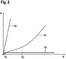
- the figure 2 shows a diagram in which three curves for a brake pressure p over a brake fluid volume V are shown.
- the curves are marked with the reference symbols 11, 12 and 13.
- curves 11, 12 and 13 are shown for a brake system 1 which is designed to carry out the diagnosis.
- the diagnosis of the brake system 1 can now be made within a range that lies between the brake fluid volume V 1 and V 2 . In this area, a breakaway force of the wheel brake 2 has already been overcome, whereas on the other hand the brake shoe 5 is not yet in contact with the brake disc 6 .
- Curves 12 and 13 show characteristic curves of wheel brake 2 when different defects occur. While curve 12 indicates the characteristic curve in the event of a hydraulic or mechanical blockage purely by way of example, curve 13 shows the characteristic curve in the event of a hydraulic leak. It is clear that in the case of curve 12 the brake pressure p rises sharply over the fluid volume V, whereas this is not the case for curve 13 .
- a reliable diagnosis of the brake system 1 can be carried out in a simple manner.
- a fully automatic implementation of the diagnosis is possible without the driver of the motor vehicle having to intervene, for example by actuating an operating element, in particular a brake pedal.
Landscapes
- Engineering & Computer Science (AREA)
- Mechanical Engineering (AREA)
- Transportation (AREA)
- General Engineering & Computer Science (AREA)
- Braking Arrangements (AREA)
- Valves And Accessory Devices For Braking Systems (AREA)
- Regulating Braking Force (AREA)
Description
- Die Erfindung betrifft ein Verfahren zum Betreiben eines Bremssystems für ein Kraftfahrzeug, wobei das Bremssystem über eine Bremsdruckquelle und wenigstens eine Radbremse verfügt, die mit einem mittels der Bremsdruckquelle bereitgestellten, auf einen Bremskolben wirkenden Bremsdruck beaufschlagbar ist. Die Erfindung betrifft weiterhin ein Bremssystem für ein Kraftfahrzeug.
DE 102 24 971 A1 D1 beschreibt die Möglichkeit des Anlegens des Bremsbelages an die Bremsscheibe mittels einer Bremsdruckquelle. - Darüber hinaus zeigt
WO 2009/083216 A2 , wie man aus dem Bremsdruckverlauf das Lüftspiel ermittelt werden kann. - Das Bremssystem dient dem Verzögern des Kraftfahrzeugs, insoweit also dem Bereitstellen einer auf ein Rad des Kraftfahrzeugs wirkenden Bremskraft. Die Bremskraft ist mithilfe der Radbremse auf das wenigstens eine Rad aufprägbar. Verfügt das Kraftfahrzeug über mehr als das eine Rad, also über wenigstens zwei Räder, so weist das Bremssystem vorzugsweise für mehrere dieser Räder oder alle der Räder jeweils eine Radbremse auf, mittels welcher auf das entsprechende Rad die Bremskraft aufprägbar ist. Nachfolgend wird lediglich auf die wenigstens eine Radbremse eingegangen. Die Ausführungen sind jedoch auf mehrere Radbremsen - sofern vorgesehen - übertragbar. Beispielsweise wird an der Radbremse bei der Betätigung eines Bedienelements ein Istbremsdruck angelegt. Das Bremssystem liegt insoweit als Betriebsbremse des Kraftfahrzeugs vor oder bildet zumindest einen Bestandteil der Betriebsbremse.
- Das Bremssystem verfügt beispielsweise über einen Hauptbremszylinder, in welchem ein Hauptbremskolben verlagerbar angeordnet ist. Der Hauptbremskolben begrenzt zusammen mit dem Hauptbremszylinder ein Bremsfluidvolumen, welches variabel ist, wobei seine Größe von der Stellung des Hauptbremskolbens abhängig ist. Der Hauptbremskolben ist mit einem Bedienelement gekoppelt, welches beispielsweise als Bremspedal vorliegt. Über das Bedienelement kann ein Fahrer des Kraftfahrzeugs eine gewünschte Bremskraft einstellen, welche nachfolgend als Vorgabebremskraft bezeichnet wird und vorzugsweise in festem Zusammenhang mit einem Vorgabebremsdruck steht. Selbstverständlich kann der Hauptbremszylinder auch entfallen und die Vorgabebremskraft beziehungsweise der Vorgabebremsdruck allein mittels des Bedienelements eingestellt werden.
- Das Bremssystem liegt bevorzugt als elektrohydraulisches Bremssystem vor. Das bedeutet, das in zumindest einer Betriebsart des Bremssystems das in dem Bremsfluidvolumen vorliegende Bremsfluid bei einer Betätigung des Bedienelements nicht unmittelbar den an der Radbremse anliegenden Istbremsdruck bereitstellt oder allenfalls einen Teil von diesem bereitstellt. Vielmehr ist vorgesehen, bei der Betätigung des Bedienelements einen Sollbremsdruck zu ermitteln, wobei dies mithilfe wenigstens eines Sensors vorgesehen sein kann, welcher dem Bedienelement und/oder dem Hauptbremskolben und/oder dem Hauptbremszylinder und/oder einem Simulatorzylinder, in welchem ein Simulatorkolben verlagerbar angeordnet ist, zugeordnet ist.
- Der Sensor kann beispielsweise als Wegsensor oder als Drucksensor ausgestaltet sein. In ersterem Fall wird mithilfe des Sensors die Betätigungsstrecke des Bedienelements ermittelt, um welche das Bedienelement bei seiner Betätigung verlagert wird. Zusätzlich oder alternativ kann selbstverständlich der in dem Hauptbremszylinder vorliegende Druck mittels des Sensors ermittelt werden. Aus den mithilfe des Sensors gemessenen Größen, also beispielsweise dem Weg und/oder dem Druck, wird anschließend der Sollbremsdruck ermittelt. Nachfolgend wird an der Radbremse ein Istbremsdruck angelegt beziehungsweise eingestellt, welcher dem Sollbremsdruck entspricht.
- Der Istbremsdruck wird dabei von der Bremsdruckquelle bereitgestellt, welche beispielsweise in Form einer Pumpe vorliegt, insbesondere einer elektrisch betriebenen Pumpe. In der vorstehend beschriebenen Betriebsart des Bremssystems ist insoweit das Bremsfluidvolumen nicht oder zumindest nicht unmittelbar mit der Radbremse verbunden beziehungsweise strömungsverbunden. Zur Bereitstellung einer Rückfallebene bei einem Defekt des Bremssystems, beispielsweise bei einem Ausfall der Bremsdruckquelle, liegt vorzugsweise eine unmittelbar Strömungsverbindung zwischen dem Hauptbremszylinder und der Radbremse vor. Auf diese Art und Weise kann auch bei einem Defekt des Bremssystems bei einer Betätigung des Bedienelements an der Radbremse ein Istbremsdruck aufgebaut werden. Hierzu muss der Fahrer jedoch eine wesentlich größere Bedienkraft auf das Bedienelement aufbringen als üblich.
- Es ist nun Aufgabe der Erfindung, ein Verfahren zum Betreiben eines Bremssystems für ein Kraftfahrzeug vorzuschlagen, welches gegenüber bekannten Verfahren Vorteile aufweist, insbesondere unabhängig von dem Antriebssystem einen zuverlässigen Betrieb des Bremssystems ermöglicht.
- Dies wird erfindungsgemäß mit einem Verfahren mit den Merkmalen des Anspruchs 1 erreicht. Dabei ist vorgesehen, dass zum Durchführen einer Diagnose des Bremssystems die Radbremse mit einem einem Diagnosebremsdruck entsprechenden, eine bestimmte Kraft auf den Bremskolben bewirkenden Bremsdruck beaufschlagt und auf den Bremskolben eine der Kraft entgegen gerichtete Gegenkraft aufgebracht wird, sodass das Aufbauen einer Bremskraft an der Radbremse unterbunden wird, insbesondere eine mit dem Bremskolben verbundene Bremsbacke beabstandet von einer Bremsscheibe oder einer Bremstrommel der Radbremse verbleibt.
- Die Radbremse weist den Bremskolben auf, der vorzugsweise in einem Bremszylinder verlagerbar, insbesondere linear verlagerbar, angeordnet ist. Mittels des Bremskolbens kann eine durch die Beaufschlagung der Radbremse mit Bremsfluid erzeugte Kraft auf eine Bremsbacke der Radbremse aufgeprägt werden, wobei an der Bremsbacke insbesondere ein Bremsbelag vorliegt.
- Insbesondere im Zuge der Einführung rekuperationsfähiger Antriebseinrichtungen für Kraftfahrzeuge, bei welchen ein Teil der Bewegungsenergie des Kraftfahrzeugs während eines Bremsvorgangs in eine speicherfähige Energieform, beispielsweise Elektroenergie, überführt wird, gewinnen sogenannte blendingfähige Bremssysteme zunehmend an Bedeutung. Diese können den Bremsdruck beziehungsweise Istbremsdruck, welche an der Radbremse anliegt, unabhängig der von der von dem Fahrer angeforderten Vorgabebremskraft variieren, insbesondere auf eine Istbremskraft einstellen, welche kleiner ist als die Vorgabebremskraft. Die Differenz der an der Radbremse eingestellten Istbremskraft zu der Vorgabebremskraft wird durch Rekuperation unter Verwendung der Antriebseinrichtung bewirkt.
- Ein energetisch besonders vorteilhafter Betriebsbereich eines derartigen Kraftfahrzeugs ist jener, bei dem die Verzögerung des Kraftfahrzeugs vollständig durch das Wirken von Triebstrangmomenten realisiert wird. Hierzu muss der Bremsdruck, der auf die Radbremse wirkt, zumindest nahezu oder gleich Null sein, damit durch diese kein Bremsmoment beziehungsweise keine Bremskraft erzeugt wird. Je nach Auslegung des Triebstrangs, insbesondere abhängig von der installierten Rekuperationsleistung, kann der so abgedeckte, rein rekuperativ dargestellte Verzögerungsbereich so groß sein, dass die Mehrzahl oder alle der Verzögerungsvorgänge innerhalb eines Fahrzyklus auf diese Art dargestellt werden können.
- An die Betriebsbremse des Kraftfahrzeugs werden aufgrund ihrer elementaren Bedeutung für die Fahrsicherheit höchste Ansprüche bezüglich ihrer Zuverlässigkeit gestellt. Konventionelle Bremssysteme werden diesen durch betriebsbewährte Konstruktion und Auslegung gerecht und bieten zudem durch häufige Betätigung die Möglichkeit, Einschränkungen der Funktion relativ frühzeitig und in statistisch betrachtet wenig gefährlichen Fahrsituationen zu erkennen. Eine wichtige Ausfallursache besteht in Undichtigkeiten des hydraulischen Systems, die zu Verlust von Bremsflüssigkeit und/oder der Unmöglichkeit hydraulischen Druckaufbaus führen.
- Die genannten Auswirkungen können selbsttätig (beispielsweise durch Füllstandsmessung im Vorratsbehälter und Aktivieren einer Warnlampe bei Unterschreiten eines Mindestfüllstands) oder durch Mitwirkung des Fahrers (Bewertung des Bremspedalwegs und/oder der Betätigungskraft) erkannt werden. Durch redundante Auslegung der Bremskreise und sich in den meisten Fällen nur schleichend vergrößernde Auswirkungen der genannten Fehler ist eine hohe Ausfallsicherheit des Bremssystems realisiert.
- Die Diagnose des Bremssystems dient der Feststellung seiner Funktionsfähigkeit. Im Rahmen der Diagnose wird insoweit festgestellt, ob mittels der Radbremse die bestimmte Kraft auf den Bremskolben bewirkt werden kann beziehungsweise ob dies, insbesondere aufgrund von Undichtigkeiten, nicht möglich ist. Die Radbremse verfügt zusätzlich zu dem Bremskolben und der Bremsbacke beziehungsweise dem Bremsbelag über die Bremsscheibe oder die Bremstrommel.
- Im Falle der Bremsscheibe liegt eine Ausgestaltung als Scheibenbremse und im Falle der Bremstrommel als Trommelbremse vor. Selbstredend sind grundsätzlich auch andere Bremsen realisierbar. Von Bedeutung ist hierbei stets, dass das Aufbauen der Bremskraft an der Radbremse unterbunden wird, also auf das Rad, welchem die Radbremse zugeordnet ist, keine oder zumindest nur eine vernachlässigbare Bremskraft wirkt.
- Während eines Bremsvorgangs des Kraftfahrzeugs mittels der Radbremse wird die Bremsbacke beziehungsweise der Bremsbelag von dem Bremskolben in Richtung der Bremsscheibe/die Bremstrommel beziehungsweise an die Bremsscheibe/Bremstrommel gedrängt, sodass ein Reibkontakt zwischen der Bremsbacke beziehungsweise dem Bremsbelag und der Bremsscheibe oder der Bremstrommel auftritt.
- Das Durchführen der Diagnose soll nun jedoch derart erfolgen, dass mittels der Radbremse keine Bremskraft auf das entsprechende Rad aufgeprägt wird. Das bedeutet, dass während der Diagnose verhindert werden muss, dass die Bremsbacke beziehungsweise der Bremsbelag in Berührkontakt mit der Bremsscheibe oder der Bremstrommel tritt. Entsprechend wird zwar die Radbremse mit dem Bremsdruck, welcher dem Diagnosebremsdruck entspricht, beaufschlagt, zugleich jedoch auf den Bremskolben die Gegenkraft aufgebracht.
- Die Gegenkraft ist der Kraft entgegengerichtet, weist jedoch in wenigstens einer Stellung des Bremskolbens denselben Betrag auf, sodass bei konstant bleibendem Bremsdruck auch der Bremskolben seine Stellung beibehält. Entsprechend wird auch bei an der Radbremse vorliegendem Bremsdruck ein Wirkkontakt zwischen Bremsbacke beziehungsweise Bremsbelag und Bremsscheibe verhindert, nämlich indem die Gegenkraft derart gewählt und aufgebracht wird, dass die Bremsbacke beziehungsweise der Bremsbelag beabstandet von der Bremsscheibe oder der Bremstrommel verbleibt.
- Es ist vorgesehen, dass die Diagnose bei durch einen Fahrer des Kraftfahrzeugs unbetätigter Radbremse durchgeführt wird. Vorstehend wurde erläutert, dass der Fahrer des Kraftfahrzeugs die Radbremse üblicherweise durch Betätigen des Bedienelements betätigt, wobei besonders bevorzugt mittels eines Sensors die von dem Fahrer gewünschte Vorgabebremskraft beziehungsweise der entsprechende Vorgabebremsdruck ermittelt wird. Es ist vorgesehen, dass die Diagnose des Bremssystems erfolgt, wenn die Vorgabebremskraft unter einem bestimmten Schwellenwert liegt, insbesondere gleich Null ist. Der an der Radbremse zum Durchführen der Diagnose angelegte Bremsdruck beziehungsweise Diagnosebremsdruck wird insoweit mittels der in diesem Fall bevorzugt als Pumpe ausgestalteten Bremsdruckquelle bereitgestellt.
- Eine Weiterbildung der Erfindung sieht vor, dass der Bremskolben zum Aufbringen der Gegenkraft mittels einer Blockiereinrichtung festgesetzt wird. Die Blockiereinrichtung kann grundsätzlich beliebig ausgestaltet sein, solange sie den Bremskolben in einer bestimmten Stellung festsetzt, in welcher die Bremsbacke beziehungsweise der Bremsbelag beabstandet von der Bremsscheibe oder der Bremstrommel vorliegt. Die Blockiereinrichtung kann beispielsweise als Stellbolzen vorliegen, welcher den Bremskolben in einer ersten Stellung festsetzt und in einer zweiten Stellung zur Verlagerung freigibt.
- Die Ausgestaltung der Erfindung sieht vor, dass die Radbremse ein von einer ersten Lüftspielstellung und einer zweiten Lüftspielstellung begrenztes Lüftspiel aufweist, indem die Bremsbacke beziehungsweise der Bremsbelag unter Einhaltung eines Abstands in Richtung der Bremsscheibe oder der Bremstrommel verlagert werden kann, und dass der Bremskolben mittels einer Rückstelleinrichtung derart kraftbeaufschlagt wird, dass die Gegenkraft zwischen der ersten Lüftspielstellung und der zweiten Lüftspielstellung auf eine zum Festsetzen des Bremskolbens benötigte Kraft eingestellt wird. Unter dem Lüftspiel ist ein Abstand der Bremsbacke beziehungsweise des Bremsbelags von der Bremsscheibe oder der Bremstrommel zu verstehen, welcher bei unbetätigter Radbremse vorliegt.
- Die erste Lüftspielstellung kann beispielsweise einer Ruhestellung des Bremskolbens beziehungsweise der Bremsbacke oder des Bremsbelags entsprechen, welche bei unbetätigter Radbremse vorliegt. Alternativ kann die erste Lüftspielstellung auch von dieser Ausgangsstellung beabstandet vorliegen und insoweit zwischen der Ausgangsstellung und der zweiten Lüftspielstellung angeordnet sein.
- Die zweite Lüftspielstellung ist beispielsweise eine Stellung, in welcher die Bremsbacke beziehungsweise der Bremsbelag gerade so weit von der Bremsscheibe entfernt ist, dass er nicht mit ihr in Berührkontakt steht. In der zweiten Lüftspielstellung liegt also ein wesentlich geringerer Abstand der Bremsbacke beziehungsweise des Bremsbelags von der Bremsscheibe oder der Bremstrommel vor als in der ersten Lüftspielstellung. Innerhalb des Lüftspiels kann die Bremsbacke beziehungsweise der Bremsbelag unter Einhaltung des Abstands in Richtung der Bremsscheibe oder der Bremstrommel verlagert werden. Entsprechend liegt innerhalb des Lüftspiels stets die Bremsbacke beziehungsweise der Bremsbelag von der Bremsscheibe oder der Bremstrommel beabstandet vor.
- Das Bremssystem beziehungsweise die Radbremse weist nun die Rückstelleinrichtung vor, welche eine Federkraft auf den Bremskolben bewirkt. Die mittels der Rückstelleinrichtung erzeugte Federkraft entspricht der Gegenkraft, welche der durch den Bremsdruck bewirkten Kraft entgegengerichtet ist. Die Gegenkraft wird dabei derart gewählt, dass sie den Bremskolben zwischen der ersten Lüftspielstellung und der zweiten Lüftspielstellung festsetzt, dass also der Bremskolben zunächst aus seiner Ausgangsstellung heraus und in Richtung der zweiten Lüftspielstellung verlagert wird. Besonders bevorzugt ist die Gegenkraft derart gewählt, dass der Bremskolben zwischen der ersten Lüftspielstellung und der zweiten Lüftspielstellung oder alternativ in der zweiten Lüftspielstellung festgesetzt wird.
- Eine weitere bevorzugte Ausführungsform der Erfindung sieht vor, dass die Gegenkraft zwischen der ersten Lüftspielstellung und der zweiten Lüftspielstellung, insbesondere ausgehend von der ersten Lüftspielstellung und/oder bis hin zu der zweiten Lüftspielstellung, größer werdend eingestellt wird. Besonders bevorzugt wächst die Gegenkraft über der zwischen der ersten Lüftspielstellung und der zweiten Lüftspielstellung liegenden Strecke mit einem bestimmten Verlauf an. Der Verlauf kann beispielsweise linear sein. Insbesondere ist es vorgesehen, dass die Gegenkraft über die Strecke in Richtung der zweiten Lüftspielstellung durchgehend ansteigt, insbesondere stetig beziehungsweise kontinuierlich. Der Anstieg der Gegenkraft beginnt beispielsweise in der ersten Lüftspielstellung und/oder endet in der zweiten Lüftspielstellung.
- Eine Weiterbildung der Erfindung sieht vor, dass die Gegenkraft durchgehend größer werdend eingestellt wird, insbesondere entsprechend eines bestimmten Verlaufs größer werdend. Hierauf wurde vorstehend bereits hingewiesen. Unter dem durchgehenden Größerwerden der Gegenkraft ist zu verstehen, dass diese über das Lüftspiel in Richtung der zweiten Lüftspielstellung hinweg nicht absinkt, sondern stets größer wird. Hierbei wird insbesondere der bestimmte Verlauf über der Strecke herangezogen.
- Eine besonders bevorzugte weitere Ausführungsform der Erfindung sieht vor, dass die Gegenkraft in dem Lüftspiel oder über das Lüftspiel um mindestens 25 %, mindestens 50 %, mindestens 75 % oder mindestens 100 % größer werdend eingestellt wird. Beispielsweise liegt also in einer ersten Stellung des Bremskolbens eine erste Gegenkraft und in einer zweiten Stellung eine zweite Gegenkraft vor. Die erste Stellung liegt dabei näher an der ersten Lüftspielstellung als die zweite Stellung beziehungsweise umgekehrt die zweite Stellung näher an der zweiten Lüftspielstellung als an der ersten Lüftspielstellung. Es kann vorgesehen sein, dass die erste Stellung der ersten Lüftspielstellung und/oder die zweite Stellung der zweiten Lüftspielstellung entspricht. Die zweite Gegenkraft ist nun größer als die erste Gegenkraft, insbesondere um die genannten Werte.
- Eine Weiterbildung der Erfindung sieht vor, dass als Bremsdruckquelle eine automatische Bremsdruckquelle verwendet wird. Die automatische Bremsdruckquelle liegt beispielsweise als Pumpe oder dergleichen vor. Die Bremsdruckquelle wird zum Durchführen der Diagnose mittels eines Steuergeräts zum Erzeugen des Bremsdrucks angesteuert, wobei das Steuergerät insbesondere auch zur Durchführung der Diagnose vorgesehen ist.
- Schließlich kann im Rahmen einer weiteren bevorzugten Ausführungsform der Erfindung vorgesehen sein, dass bei der Diagnose ein der Radbremse zugeführtes Bremsfluidvolumen ermittelt wird. Auf derartige Art und Weise kann die Funktionsfähigkeit der Radbremse besonders zuverlässig festgestellt werden. Zum Betätigen der Radbremse und zum Durchführen der Diagnose ist es jeweils vorgesehen, der Radbremse mittels der Bremsdruckquelle Bremsfluid zuzuführen. Beispielsweise wird dieses Bremsfluid zuvor einem Vorratsbehälter entnommen.
- Bevorzugt wird das der Radbremse während der Diagnose zugeführte Bremsfluidvolumen mittels eines Massenstrommessgeräts ermittelt, dessen Messwerte erfasst und über der Zeit aufsummiert oder integriert werden. Anschließend wird aus dem ermittelten Bremsfluidvolumen diejenige Stellung des Bremskolbens ermittelt, welche aufgrund des der Radbremse zugeführten Bremsfluidvolumens vorliegen sollte. Zudem wird beispielsweise die tatsächliche Stellung des Bremskolbens ermittelt. Weichen die beiden Stellungen voneinander ab, so kann auf einen Defekt der Radbremse und/oder des Bremssystems geschlossen werden. Anstelle des Massenstrommessgeräts kann ein Volumenstrommessgerät verwendet werden.
- Alternativ oder zusätzlich ist es selbstredend möglich, das Bremsfluidvolumen auf andere Art und Weise zu bestimmen. Beispielsweise kann hierzu die Kolbenposition einer Pumpe herangezogen werden, welche entweder direkt mittels eines Sensors oder indirekt mittels eines Modells bestimmt wird. Auch bei Verwendung einer kontinuierlich oder quasikontinuierlich arbeitenden Pumpe, beispielsweise eine Radialkolben- oder Zahnradpumpe, kann aus den Eigenschaften und der Betriebsweise der Pumpe der Massenstrom beziehungsweise Volumenstrom rechnerisch bestimmt und integriert oder aufsummiert werden.
- Die Erfindung betrifft weiterhin ein Bremssystem für ein Kraftfahrzeug, insbesondere zur Durchführung des vorstehend beschriebenen Verfahrens, wobei das Bremssystem über eine Bremsdruckquelle und wenigstens eine Radbremse verfügt, die mit einem mittels der Bremsdruckquelle bereitgestellten, auf einen Bremskolben wirkenden Bremsdruck beaufschlagbar ist.
- Dabei ist vorgesehen, dass das Bremssystem zur Durchführung einer Diagnose des Bremssystems dazu ausgebildet ist, die Radbremse mit einem einem Diagnosebremsdruck entsprechenden, eine bestimmte Kraft auf den Bremskolben bewirkenden Bremsdruck zu beaufschlagen und auf den Bremskolben eine der Kraft entgegen gerichtete Gegenkraft aufzubringen, sodass das Aufbauen einer Bremskraft an der Radbremse unterbunden wird, insbesondere eine mit dem Bremskolben verbundene Bremsbacke beabstandet von einer Bremsscheibe oder einer Bremstrommel der Radbremse verbleibt.
- Auf die Vorteile einer derartigen Ausgestaltung des Bremssystems beziehungsweise einer derartigen Vorgehensweise wurde bereits hingewiesen. Sowohl das Bremssystem für das Kraftfahrzeug als auch das Verfahren zu seinem Betreiben können gemäß den vorstehenden Ausführungen weitergebildet sein, sodass insoweit auf diese verwiesen wird. Wie vorstehend bereits erläutert, kann es vorgesehen sein, dass das Bremssystem derart ausgestaltet ist, dass es ein der Radbremse während der Diagnose zugeführte Bremsfluidvolumen ermittelt, insbesondere direkt oder indirekt.
- Im Rahmen der Erfindung ist schließlich vorgesehen, dass die Radbremse ein von einer ersten Lüftspielstellung und einer zweiten Lüftspielstellung begrenztes Lüftspiel aufweist, in dem die Bremsbacke beziehungsweise der Bremsbelag unter Einhaltung eines Abstands in Richtung der Bremsscheibe oder der Bremstrommel verlagerbar ist, und dass der Bremskolben mittels einer Rückstelleinrichtung kraftbeaufschlagbar ist, wobei die Rückstelleinrichtung derart ausgebildet ist, dass die Gegenkraft zwischen der ersten Lüftspielstellung und der zweiten Lüftspielstellung einer zum Festsetzen des Bremskolbens benötigten Kraft entspricht. Auch hierzu wird auf die vorstehenden Ausführungen verwiesen.
- Die Erfindung wird nachfolgend anhand der in der Zeichnung dargestellten Ausführungsbeispiele näher erläutert, ohne dass eine Beschränkung der Erfindung erfolgt. Dabei zeigt:
- Figur 1
- eine schematische Darstellung eines Bereichs eines Bremssystems für ein Kraftfahrzeug, nämlich eines Bereichs einer Radbremse, sowie
- Figur 2
- ein Diagramm, in welchem unterschiedliche Kennlinien für einen Bremsdruck der Radbremse über einem der Radbremse zugeführten Bremsfluidvolumen aufgetragen sind.
- Die
Figur 1 zeigt eine schematische Darstellung eines Bereichs eines Bremssystems 1, nämlich eines Bereichs einer Radbremse 2. Die Radbremse 2 verfügt über wenigstens einen Bremskolben 3, welcher in einem Bremszylinder 4 linear verlagerbar angeordnet ist. Der Bremskolben 3 ist mit einer Bremsbacke 5 verbunden, welche zum Bewirken einer Bremskraft mit einer Bremsscheibe 6 in Anlagekontakt treten kann. Die Bremsbacke 5 verfügt bevorzugt auf ihrer der Bremsscheibe 6 zugewandten Seite über einen Bremsbelag. Die Radbremse 2 liegt in dem hier vorgestellten Ausführungsbeispiel als Scheibenbremse vor. Selbstverständlich ist jedoch auch eine Ausgestaltung als Trommelbremse oder dergleichen möglich. - In dem hier dargestellten Ausführungsbeispiel sind zwei gegenüberliegende Bremskolben 3 und entsprechend zwei sich bezüglich der Bremsscheibe 6 gegenüberliegende Bremsbeläge 5 vorgesehen. Beide Bremszylinder 4 sind über eine gemeinsame Fluidleitung 7 an weitere Bereiche des Bremssystems 1 angeschlossen, insbesondere an eine Bremsdruckquelle. Nachfolgend wird lediglich auf einen der Bremskolben 3 und entsprechend nur einen der Bremsbeläge 5 eingegangen. Die Ausführungen sind jedoch stets analog auf den jeweils anderen Bremskolben 3 die jeweils andere Bremsbacke 5 anwendbar.
- Es ist deutlich zu erkennen, dass an dem Bremskolben 3 ein Anschlagelement 8 ausgebildet ist, welches beispielsweise in Form eines Radialvorsprungs vorliegt, der insbesondere als Kreisringvorsprung ausgestaltet ist. Das Anschlagelement 8 kann einerseits zur Realisierung eines Endanschlags vorgesehen sein. Andererseits greift an dem Anschlagelement 8 eine Rückstelleinrichtung 9 an, welche - wie hier dargestellt - wenigstens ein Federelement 10 aufweist. Die Rückstelleinrichtung 9 beaufschlagt den Bremskolben 3 mit einer Gegenkraft, die einer bei Anlegen eines Bremsdrucks an der Radbremse 2 erzeugten Kraft entgegengerichtet ist. Diese Kraft drängt den Bremskolben 3 beziehungsweise die Bremsbacke 5 in Richtung der Bremsscheibe 6. Die Gegenkraft ist entsprechend in die entgegengesetzte Richtung gerichtet und drängt den Bremskolben 3 beziehungsweise die Bremsbacke 5 von der Bremsscheibe 6 fort.
- Es ist nun vorgesehen, dass zum Durchführen einer Diagnose des Bremssystems 1 die Radbremse 2 mit einem einem Diagnosebremsdruck entsprechenden Bremsdruck beaufschlagt wird. Dieser Diagnosebremsdruck bewirkt die bestimmte Kraft auf den Bremskolben 3. Die mittels der Rückstelleinrichtung 9 bewirkte Gegenkraft wird nun derart ausgelegt, dass die Bremsbacke 5 bei Vorliegen des Diagnosebremsdrucks beabstandet von der Bremsscheibe 6 verbleibt. Übersteigt dagegen der Bremsdruck den Diagnosebremsdruck, so kann die von dem Bremsdruck bewirkte Kraft die Gegenkraft überwinden, sodass schlussendlich die Bremsbacke 5 in Wirkkontakt mit der Bremsscheibe 6 treten kann beziehungsweise tritt, sodass mittels der Radbremse 2 eine bestimmte Bremskraft auf die Bremsscheibe 6 bewirkt wird.
- Die
Figur 2 zeigt ein Diagramm, in welchem drei Verläufe für einen Bremsdruck p über ein Bremsfluidvolumen V dargestellt sind. Die Verläufe sind mit den Bezugszeichen 11, 12 und 13 gekennzeichnet. Es sei darauf hingewiesen, dass die Verläufe 11, 12 und 13 für ein Bremssystem 1 wiedergegeben sind, das zum Durchführen der Diagnose ausgestaltet ist. Der Verlauf 11 beschreibt eine Kennlinie der Radbremse 2 in funktionstüchtigem Zustand. Es ist erkennbar, dass bis zu einem Volumen von V = V1 der Bremsdruck p zunächst stärker ansteigt als dies bei infinitesimal größerem Bremsfluidvolumen V der Fall ist. Für ein Volumen von V1 < V ≤ V2 liegt das sogenannte Lüftspiel vor. In diesem steigt der Bremsdruck p über dem Bremsfluidvolumen V im Wesentlichen linear an. - Das Lüftspiel umfasst Stellungen, in welchen die Bremsbacke 5 noch nicht mit der Bremsscheibe 6 in Kontakt tritt. Dies ist erst ab dem Volumen V = V2 der Fall. Es ist erkennbar, dass für V > V2 der Bremsdruck p über dem Bremsfluidvolumen V nicht mehr linear, sondern vielmehr überproportional ansteigt. Ab dem Volumen V = V2 wird insoweit mittels der Radbremse 2 eine Bremskraft bewirkt. Die Diagnose des Bremssystems 1 kann nun innerhalb eines Bereichs vorgenommen werden, welcher zwischen dem Bremsfluidvolumen V1 und V2 liegt. In diesem Bereich ist bereits eine Losbrechkraft der Radbremse 2 überwunden, wohingegen andererseits die Bremsbacke 5 noch nicht an der Bremsscheibe 6 anliegt.
- Die Verläufe 12 und 13 zeigen Kennlinien der Radbremse 2 bei Auftreten unterschiedlicher Defekte. Während der Verlauf 12 die Kennlinie bei einer hydraulischen oder mechanischen Blockade rein beispielhaft andeutet, zeigt der Verlauf 13 die Kennlinie bei einer hydraulischen Leckage. Es wird deutlich, dass im Falle des Verlaufs 12 der Bremsdruck p über dem Fluidvolumen V stark ansteigt, wohingegen dies für den Verlauf 13 nicht der Fall ist.
- Mit der beschriebenen Ausgestaltung des Bremssystems 1 beziehungsweise mithilfe der vorstehend erläuterten Vorgehensweise kann auf einfache Art und Weise eine zuverlässige Diagnose des Bremssystems 1 durchgeführt werden. Dabei ist insbesondere eine vollautomatische Durchführung der Diagnose möglich, ohne dass ein Fahrer des Kraftfahrzeugs eingreifen muss, beispielsweise durch Betätigen eines Bedienelements, insbesondere eines Bremspedals.
Claims (9)
- Verfahren zum Betreiben eines Bremssystems (1) für ein Kraftfahrzeug, wobei das Bremssystem (1) über eine Bremsdruckquelle und wenigstens eine Radbremse (2) verfügt, die mit einem mittels der Bremsdruckquelle bereitgestellten, auf einen Bremskolben (3) wirkenden Bremsdruck beaufschlagbar ist, dadurch gekennzeichnet, dass zum Durchführen einer Diagnose des Bremssystems (1) bei durch einen Fahrer des Kraftfahrzeugs unbetätigter Radbremse (2) die Radbremse (2) mit einem einem Diagnosebremsdruck entsprechenden, eine bestimmte Kraft auf den Bremskolben (3) bewirkenden Bremsdruck beaufschlagt und auf den Bremskolben (3) eine der Kraft entgegen gerichtete Gegenkraft aufgebracht wird, sodass das Aufbauen einer Bremskraft an der Radbremse (2) unterbunden wird, wobei die Radbremse (2) ein von einer ersten Lüftspielstellung und einer zweiten Lüftspielstellung begrenztes Lüftspiel aufweist, indem eine mit dem Bremskolben (3) verbundene Bremsbacke (5) unter Einhaltung eines Abstands in Richtung einer Bremsscheibe (6) oder einer Bremstrommel der Radbremse (2) verlagert werden kann, und dass der Bremskolben (3) mittels einer Rückstelleinrichtung (9) derart kraftbeaufschlagt wird, dass die Gegenkraft zwischen der ersten Lüftspielstellung und der zweiten Lüftspielstellung auf eine zum Festsetzen des Bremskolbens (3) benötigte Kraft eingestellt wird.
- Verfahren nach Anspruch 1, dadurch gekennzeichnet, dass der Bremskolben (3) zum Aufbringen der Gegenkraft mittels einer Blockiereinrichtung festgesetzt wird.
- Verfahren nach einem der vorhergehenden Ansprüche, dadurch gekennzeichnet, dass die Gegenkraft zwischen der ersten Lüftspielstellung und der zweiten Lüftspielstellung, insbesondere ausgehend von der ersten Lüftspielstellung und/oder bis hin zu der zweiten Lüftspielstellung, größer werdend eingestellt wird.
- Verfahren nach einem der vorhergehenden Ansprüche, dadurch gekennzeichnet, dass die Gegenkraft durchgehend größer werdend eingestellt wird, insbesondere entsprechend eines bestimmten Verlaufs größer werdend.
- Verfahren nach einem der vorhergehenden Ansprüche, dadurch gekennzeichnet, dass die Gegenkraft in dem Lüftspiel oder über das Lüftspiel um mindestens 25 %, mindestens 50 %, mindestens 75 % oder mindestens 100 % größer werdend eingestellt wird.
- Verfahren nach einem der vorhergehenden Ansprüche, dadurch gekennzeichnet, dass als Bremsdruckquelle eine automatische Bremsdruckquelle verwendet wird.
- Verfahren nach einem der vorhergehenden Ansprüche, dadurch gekennzeichnet, dass bei der Diagnose ein der Radbremse (2) zugeführtes Bremsfluidvolumen (V) ermittelt wird.
- Bremssystem (1) für ein Kraftfahrzeug, insbesondere zur Durchführung des Verfahrens nach einem oder mehreren der vorhergehenden Ansprüche, wobei das Bremssystem (1) über eine Bremsdruckquelle und wenigstens eine Radbremse (2) verfügt, die mit einem mittels der Bremsdruckquelle bereitgestellten, auf einen Bremskolben (3) wirkenden Bremsdruck beaufschlagbar ist, dadurch gekennzeichnet, dass das Bremssystem (1) zur Durchführung einer Diagnose des Bremssystems (1) dazu ausgebildet ist, bei durch einen Fahrer des Kraftfahrzeugs unbetätigter Radbremse (2) die Radbremse (2) mit einem einem Diagnosebremsdruck entsprechenden, eine bestimmte Kraft auf den Bremskolben (3) bewirkenden Bremsdruck zu beaufschlagen und auf den Bremskolben (3) eine der Kraft entgegen gerichtete Gegenkraft aufzubringen, sodass das Aufbauen einer Bremskraft an der Radbremse (2) unterbunden wird, wobei die Radbremse (2) ein von einer ersten Lüftspielstellung und einer zweiten Lüftspielstellung begrenztes Lüftspiel aufweist, indem eine mit dem Bremskolben (3) verbundene Bremsbacke (5) unter Einhaltung eines Abstands in Richtung einer Bremsscheibe (6) oder einer Bremstrommel der Radbremse (2) verlagert werden kann, und dass der Bremskolben (3) mittels einer Rückstelleinrichtung (9) derart kraftbeaufschlagt wird, dass die Gegenkraft zwischen der ersten Lüftspielstellung und der zweiten Lüftspielstellung auf eine zum Festsetzen des Bremskolbens (3) benötigte Kraft eingestellt wird.
- Bremssystem nach Anspruch 8, dadurch gekennzeichnet, dass die Radbremse (2) ein von einer ersten Lüftspielstellung und einer zweiten Lüftspielstellung begrenztes Lüftspiel aufweist, indem die Bremsbacke (5) unter Einhaltung eines Abstands in Richtung der Bremsscheibe (6) oder der Bremstrommel verlagerbar ist, und dass der Bremskolben (3) mittels einer Rückstelleinrichtung (9) kraftbeaufschlagbar ist, wobei die Rückstelleinrichtung (9) derart ausgebildet ist, dass die Gegenkraft zwischen der ersten Lüftspielstellung und der zweiten Lüftspielstellung einer zum Festsetzen des Bremskolbens (3) benötigten Kraft entspricht.
Applications Claiming Priority (2)
| Application Number | Priority Date | Filing Date | Title |
|---|---|---|---|
| DE102017202813.0A DE102017202813A1 (de) | 2017-02-22 | 2017-02-22 | Verfahren zum Betreiben eines Bremssystems eines Kraftfahrzeugs sowie entsprechendes Bremssystem |
| PCT/EP2018/051716 WO2018153607A1 (de) | 2017-02-22 | 2018-01-24 | Verfahren zur diagnose eines bremssystems eines kraftfahrzeugs sowie entsprechendes bremssystem |
Publications (2)
| Publication Number | Publication Date |
|---|---|
| EP3585666A1 EP3585666A1 (de) | 2020-01-01 |
| EP3585666B1 true EP3585666B1 (de) | 2022-04-20 |
Family
ID=61163679
Family Applications (1)
| Application Number | Title | Priority Date | Filing Date |
|---|---|---|---|
| EP18703241.2A Active EP3585666B1 (de) | 2017-02-22 | 2018-01-24 | Verfahren zur diagnose eines bremssystems eines kraftfahrzeugs sowie entsprechendes bremssystem |
Country Status (5)
| Country | Link |
|---|---|
| US (1) | US11034339B2 (de) |
| EP (1) | EP3585666B1 (de) |
| CN (1) | CN110325418B (de) |
| DE (1) | DE102017202813A1 (de) |
| WO (1) | WO2018153607A1 (de) |
Families Citing this family (5)
| Publication number | Priority date | Publication date | Assignee | Title |
|---|---|---|---|---|
| DE102018218693A1 (de) * | 2018-06-25 | 2020-01-02 | Continental Teves Ag & Co. Ohg | Verfahren zum Überwachen eines hydraulischen Bremssystems für ein Kraftfahrzeug und Bremssystem |
| US12263820B2 (en) * | 2020-07-31 | 2025-04-01 | New York Air Brake, LLC | Excessive train brake pipe flow diagnostics |
| CN112744191B (zh) * | 2021-02-02 | 2021-10-29 | 河南工业贸易职业学院 | 一种汽车用安全刹车装置 |
| DE102021130305B4 (de) | 2021-11-19 | 2025-10-02 | Hl Mando Corporation | Reduzierung des Restschleifmoments bei einer Scheibenbremse |
| DE102023118244A1 (de) * | 2023-07-11 | 2025-01-16 | Audi Aktiengesellschaft | Verfahren zum Betreiben einer Bremsanlage für ein Kraftfahrzeug, entsprechende Bremsanlage für ein Kraftfahrzeug sowie Computerprogrammprodukt |
Family Cites Families (23)
| Publication number | Priority date | Publication date | Assignee | Title |
|---|---|---|---|---|
| US2485086A (en) * | 1948-03-15 | 1949-10-18 | Toby T Cagle | Wheel brake assembly with adjustable releasing means |
| US3991860A (en) * | 1975-04-24 | 1976-11-16 | Westinghouse Air Brake Company | Means enabling replacement of worn disc brake shoes without disassembly |
| DE3435089C2 (de) | 1984-09-25 | 1995-11-30 | Teves Gmbh Alfred | Verfahren zur Überprüfung der Dichtheit von hydraulischen Bremsanlagen bei mit Bremsschlupfregelanlagen ausgerüsteten Kraftfahrzeugen |
| US5348123A (en) * | 1991-09-02 | 1994-09-20 | Akebono Brake Industry Co., Ltd. | Brake actuating apparatus for a vehicle |
| US5613577A (en) | 1994-12-09 | 1997-03-25 | Ford Motor Company | Automotive disc brake with improved caliper assembly |
| DE19507308A1 (de) | 1995-03-02 | 1996-09-05 | Perrot Bremsen Gmbh | Scheibenbremse |
| DE19510933A1 (de) | 1995-03-24 | 1996-09-26 | Wabco Gmbh | Verfahren zur Ermittlung des Ansprechdrucks einer durch Druck betätigten Bremse in einem Fahrzeugbremssystem |
| DE19515063C2 (de) * | 1995-04-27 | 2002-06-06 | Knorr Bremse Systeme | Scheibenbremse für Fahrzeuge, insbesondere Straßenfahrzeuge |
| GB2321090B (en) * | 1997-01-14 | 2000-08-23 | T & N Technology Ltd | Brake testing |
| JPH11170991A (ja) | 1997-12-16 | 1999-06-29 | Toyota Motor Corp | 電気式ブレーキ異常判定方法 |
| JP3684985B2 (ja) * | 2000-02-28 | 2005-08-17 | 株式会社日立製作所 | ブレーキ装置 |
| DE10224971A1 (de) * | 2002-06-05 | 2003-12-24 | Bayerische Motoren Werke Ag | Verfahren zum Reinigen einer eine Bremsscheibe und Bremsbeläge umfassenden Betriebsbremse eines Fahrzeugs |
| JP4424063B2 (ja) * | 2004-05-17 | 2010-03-03 | 株式会社アドヴィックス | 常用兼駐車ブレーキ装置 |
| DE102006049794B4 (de) * | 2005-11-11 | 2017-09-21 | Continental Teves Ag & Co. Ohg | Verfahren zum Abtrocknen einer eine Bremsscheibe und Bremsbeläge umfassenden Betriebsbremse |
| EP2043895A1 (de) * | 2006-07-13 | 2009-04-08 | Renault Trucks | Verfahren zur überwachung des status einer fahrzeugfeststellbremse |
| JP5206952B2 (ja) * | 2007-08-31 | 2013-06-12 | 日立オートモティブシステムズ株式会社 | ディスクブレーキ装置 |
| EP2225132B1 (de) * | 2007-12-21 | 2011-09-14 | Ipgate Ag | Bremsanlage mit mindestens einer förderungseinrichtung zum nachfördern von bremsflüssigkeit in die arbeitsräume eines bremskraftverstärkers |
| DE102008020566A1 (de) | 2008-04-24 | 2009-10-29 | Lucas Automotive Gmbh | Bestimmung einer Leistungsfähigkeit einer Kraftfahrzeug-Hydraulikpumpe |
| DE102008034769A1 (de) * | 2008-07-25 | 2010-01-28 | Robert Bosch Gmbh | Verfahren zum Betreiben einer Bremsanlage eines Kraftfahrzeugs sowie Kraftfahrzeug |
| US8118256B2 (en) * | 2008-10-10 | 2012-02-21 | Goodrich Corporation | Brake shutoff valve test |
| WO2012105526A1 (ja) | 2011-01-31 | 2012-08-09 | 本田技研工業株式会社 | 車両用ブレーキ装置 |
| CN103459880B (zh) | 2011-12-12 | 2016-03-30 | 三菱电机株式会社 | 电磁制动器状态诊断装置及其方法 |
| DE102015106089A1 (de) * | 2015-04-21 | 2016-10-27 | Ipgate Ag | Diagnoseverfahren für ein Bremssystem |
-
2017
- 2017-02-22 DE DE102017202813.0A patent/DE102017202813A1/de not_active Withdrawn
-
2018
- 2018-01-24 US US16/487,944 patent/US11034339B2/en active Active
- 2018-01-24 EP EP18703241.2A patent/EP3585666B1/de active Active
- 2018-01-24 CN CN201880013270.2A patent/CN110325418B/zh active Active
- 2018-01-24 WO PCT/EP2018/051716 patent/WO2018153607A1/de not_active Ceased
Also Published As
| Publication number | Publication date |
|---|---|
| DE102017202813A1 (de) | 2018-08-23 |
| WO2018153607A1 (de) | 2018-08-30 |
| EP3585666A1 (de) | 2020-01-01 |
| US11034339B2 (en) | 2021-06-15 |
| CN110325418A (zh) | 2019-10-11 |
| CN110325418B (zh) | 2021-08-03 |
| US20200039479A1 (en) | 2020-02-06 |
Similar Documents
| Publication | Publication Date | Title |
|---|---|---|
| EP3585666B1 (de) | Verfahren zur diagnose eines bremssystems eines kraftfahrzeugs sowie entsprechendes bremssystem | |
| DE102019215418B4 (de) | Verfahren zur Überwachung eines Bremsflüssigkeitsvolumens | |
| EP2651720B1 (de) | Verfahren zum einstellen der von einer feststellbremse ausgeübten klemmkraft | |
| DE102011003183A1 (de) | Verfahren zur Überwachung der Funktion einer Feststellbremse in einem Fahrzeug | |
| DE102015109630A1 (de) | Verfahren zur elektronischen Regelung der Bremskraftverteilung in einer druckmittelbetätigten Bremsanlage eines Fahrzeugs sowie druckmittelbetätigten Bremsanlage eines Fahrzeugs mit einer solchen Regelung | |
| DE102014203322A1 (de) | Verfahren zum Erzeugen einer Notverzögerung eines bewegten Fahrzeugs | |
| DE102016214195A1 (de) | Verfahren zur Funktionsprüfung einer elektromechanischen Bremsvorrichtung | |
| WO2021023411A1 (de) | Verfahren zur funktionsprüfung eines druckerzeugeraggregats einer elektronisch schlupfregelbaren fremdkraftbremsanlage mit redundanter bremsdruckerzeugung, insbesondere für ein autonom fahrbares kraftfahrzeug | |
| WO2020020518A1 (de) | Verfahren zum betreiben eines bremssystems sowie bremssystem | |
| DE102016223826A1 (de) | Verfahren und Vorrichtung zum Betreiben eines hydraulischen Bremssystems, Bremssystem | |
| WO2006084864A1 (de) | Bremsbetätigungseinheit zur betätigung einer kraftfahrzeugbremsanlage | |
| WO2012065769A2 (de) | System sowie verfahren zur bremskreisausfallerkennung | |
| EP3412926B1 (de) | Planetenrad-getriebeanordnung insbesondere für eine elektromechanische betriebsbremse oder eine elektromechanische parkbremse für ein kraftfahrzeug | |
| DE102006029979B4 (de) | Verfahren zum Betrieb einer Bremsanlage eines Kraftfahrzeuges | |
| EP4491472B1 (de) | Verfahren zum betreiben einer bremsanlage für ein kraftfahrzeug, entsprechende bremsanlage für ein kraftfahrzeug sowie computerprogrammprodukt | |
| DE102006041194A1 (de) | Verfahren zum Betrieb einer Bremsanlage eines Kraftfahrzeuges | |
| EP3331737B1 (de) | Verfahren zum überprüfen der parkbremskraft in einem fahrzeug | |
| DE102017204765B4 (de) | Verfahren zum Betreiben eines Bremssystems für ein Kraftfahrzeug sowie entsprechendes Bremssystem | |
| EP1233894B1 (de) | Verfahren zum abbremsen eines fahrzeugs und vorrichtung zur durchführung des verfahrens | |
| DE102017208058A1 (de) | Verfahren zum Abbremsen eines Fahrzeugs mit hydraulischer Fahrzeugbremse und elektromechanischer Bremsvorrichtung | |
| DE102010021935A1 (de) | Bremspedalsimulator und Bremssystem | |
| DE102006044422A1 (de) | Verfahren zum Betätigen einer elektromechanischen Parkbremse eines Fahrzeugs | |
| DE102021211336A1 (de) | Verfahren zum Betreiben eines Kraftfahrzeugs | |
| DE102024201398A1 (de) | Verfahren und Vorrichtung zum Betreiben einer elektromechanischen Bremseinrichtung, Bremseinrichtung und Bremssystem | |
| DE102023205516A1 (de) | Verfahren zum Betreiben eines Bremssystems für ein Kraftfahrzeug |
Legal Events
| Date | Code | Title | Description |
|---|---|---|---|
| STAA | Information on the status of an ep patent application or granted ep patent |
Free format text: STATUS: UNKNOWN |
|
| STAA | Information on the status of an ep patent application or granted ep patent |
Free format text: STATUS: THE INTERNATIONAL PUBLICATION HAS BEEN MADE |
|
| PUAI | Public reference made under article 153(3) epc to a published international application that has entered the european phase |
Free format text: ORIGINAL CODE: 0009012 |
|
| STAA | Information on the status of an ep patent application or granted ep patent |
Free format text: STATUS: REQUEST FOR EXAMINATION WAS MADE |
|
| 17P | Request for examination filed |
Effective date: 20190923 |
|
| AK | Designated contracting states |
Kind code of ref document: A1 Designated state(s): AL AT BE BG CH CY CZ DE DK EE ES FI FR GB GR HR HU IE IS IT LI LT LU LV MC MK MT NL NO PL PT RO RS SE SI SK SM TR |
|
| AX | Request for extension of the european patent |
Extension state: BA ME |
|
| DAV | Request for validation of the european patent (deleted) | ||
| DAX | Request for extension of the european patent (deleted) | ||
| GRAP | Despatch of communication of intention to grant a patent |
Free format text: ORIGINAL CODE: EPIDOSNIGR1 |
|
| STAA | Information on the status of an ep patent application or granted ep patent |
Free format text: STATUS: GRANT OF PATENT IS INTENDED |
|
| INTG | Intention to grant announced |
Effective date: 20220124 |
|
| GRAS | Grant fee paid |
Free format text: ORIGINAL CODE: EPIDOSNIGR3 |
|
| GRAA | (expected) grant |
Free format text: ORIGINAL CODE: 0009210 |
|
| STAA | Information on the status of an ep patent application or granted ep patent |
Free format text: STATUS: THE PATENT HAS BEEN GRANTED |
|
| AK | Designated contracting states |
Kind code of ref document: B1 Designated state(s): AL AT BE BG CH CY CZ DE DK EE ES FI FR GB GR HR HU IE IS IT LI LT LU LV MC MK MT NL NO PL PT RO RS SE SI SK SM TR |
|
| REG | Reference to a national code |
Ref country code: GB Ref legal event code: FG4D Free format text: NOT ENGLISH |
|
| REG | Reference to a national code |
Ref country code: CH Ref legal event code: EP |
|
| REG | Reference to a national code |
Ref country code: IE Ref legal event code: FG4D Free format text: LANGUAGE OF EP DOCUMENT: GERMAN |
|
| REG | Reference to a national code |
Ref country code: DE Ref legal event code: R096 Ref document number: 502018009429 Country of ref document: DE |
|
| REG | Reference to a national code |
Ref country code: AT Ref legal event code: REF Ref document number: 1484946 Country of ref document: AT Kind code of ref document: T Effective date: 20220515 |
|
| REG | Reference to a national code |
Ref country code: LT Ref legal event code: MG9D |
|
| REG | Reference to a national code |
Ref country code: NL Ref legal event code: MP Effective date: 20220420 |
|
| PG25 | Lapsed in a contracting state [announced via postgrant information from national office to epo] |
Ref country code: NL Free format text: LAPSE BECAUSE OF FAILURE TO SUBMIT A TRANSLATION OF THE DESCRIPTION OR TO PAY THE FEE WITHIN THE PRESCRIBED TIME-LIMIT Effective date: 20220420 |
|
| PG25 | Lapsed in a contracting state [announced via postgrant information from national office to epo] |
Ref country code: SE Free format text: LAPSE BECAUSE OF FAILURE TO SUBMIT A TRANSLATION OF THE DESCRIPTION OR TO PAY THE FEE WITHIN THE PRESCRIBED TIME-LIMIT Effective date: 20220420 Ref country code: PT Free format text: LAPSE BECAUSE OF FAILURE TO SUBMIT A TRANSLATION OF THE DESCRIPTION OR TO PAY THE FEE WITHIN THE PRESCRIBED TIME-LIMIT Effective date: 20220822 Ref country code: NO Free format text: LAPSE BECAUSE OF FAILURE TO SUBMIT A TRANSLATION OF THE DESCRIPTION OR TO PAY THE FEE WITHIN THE PRESCRIBED TIME-LIMIT Effective date: 20220720 Ref country code: LT Free format text: LAPSE BECAUSE OF FAILURE TO SUBMIT A TRANSLATION OF THE DESCRIPTION OR TO PAY THE FEE WITHIN THE PRESCRIBED TIME-LIMIT Effective date: 20220420 Ref country code: HR Free format text: LAPSE BECAUSE OF FAILURE TO SUBMIT A TRANSLATION OF THE DESCRIPTION OR TO PAY THE FEE WITHIN THE PRESCRIBED TIME-LIMIT Effective date: 20220420 Ref country code: GR Free format text: LAPSE BECAUSE OF FAILURE TO SUBMIT A TRANSLATION OF THE DESCRIPTION OR TO PAY THE FEE WITHIN THE PRESCRIBED TIME-LIMIT Effective date: 20220721 Ref country code: FI Free format text: LAPSE BECAUSE OF FAILURE TO SUBMIT A TRANSLATION OF THE DESCRIPTION OR TO PAY THE FEE WITHIN THE PRESCRIBED TIME-LIMIT Effective date: 20220420 Ref country code: ES Free format text: LAPSE BECAUSE OF FAILURE TO SUBMIT A TRANSLATION OF THE DESCRIPTION OR TO PAY THE FEE WITHIN THE PRESCRIBED TIME-LIMIT Effective date: 20220420 Ref country code: BG Free format text: LAPSE BECAUSE OF FAILURE TO SUBMIT A TRANSLATION OF THE DESCRIPTION OR TO PAY THE FEE WITHIN THE PRESCRIBED TIME-LIMIT Effective date: 20220720 |
|
| PG25 | Lapsed in a contracting state [announced via postgrant information from national office to epo] |
Ref country code: RS Free format text: LAPSE BECAUSE OF FAILURE TO SUBMIT A TRANSLATION OF THE DESCRIPTION OR TO PAY THE FEE WITHIN THE PRESCRIBED TIME-LIMIT Effective date: 20220420 Ref country code: PL Free format text: LAPSE BECAUSE OF FAILURE TO SUBMIT A TRANSLATION OF THE DESCRIPTION OR TO PAY THE FEE WITHIN THE PRESCRIBED TIME-LIMIT Effective date: 20220420 Ref country code: LV Free format text: LAPSE BECAUSE OF FAILURE TO SUBMIT A TRANSLATION OF THE DESCRIPTION OR TO PAY THE FEE WITHIN THE PRESCRIBED TIME-LIMIT Effective date: 20220420 Ref country code: IS Free format text: LAPSE BECAUSE OF FAILURE TO SUBMIT A TRANSLATION OF THE DESCRIPTION OR TO PAY THE FEE WITHIN THE PRESCRIBED TIME-LIMIT Effective date: 20220820 |
|
| REG | Reference to a national code |
Ref country code: DE Ref legal event code: R097 Ref document number: 502018009429 Country of ref document: DE |
|
| PG25 | Lapsed in a contracting state [announced via postgrant information from national office to epo] |
Ref country code: SM Free format text: LAPSE BECAUSE OF FAILURE TO SUBMIT A TRANSLATION OF THE DESCRIPTION OR TO PAY THE FEE WITHIN THE PRESCRIBED TIME-LIMIT Effective date: 20220420 Ref country code: SK Free format text: LAPSE BECAUSE OF FAILURE TO SUBMIT A TRANSLATION OF THE DESCRIPTION OR TO PAY THE FEE WITHIN THE PRESCRIBED TIME-LIMIT Effective date: 20220420 Ref country code: RO Free format text: LAPSE BECAUSE OF FAILURE TO SUBMIT A TRANSLATION OF THE DESCRIPTION OR TO PAY THE FEE WITHIN THE PRESCRIBED TIME-LIMIT Effective date: 20220420 Ref country code: EE Free format text: LAPSE BECAUSE OF FAILURE TO SUBMIT A TRANSLATION OF THE DESCRIPTION OR TO PAY THE FEE WITHIN THE PRESCRIBED TIME-LIMIT Effective date: 20220420 Ref country code: DK Free format text: LAPSE BECAUSE OF FAILURE TO SUBMIT A TRANSLATION OF THE DESCRIPTION OR TO PAY THE FEE WITHIN THE PRESCRIBED TIME-LIMIT Effective date: 20220420 Ref country code: CZ Free format text: LAPSE BECAUSE OF FAILURE TO SUBMIT A TRANSLATION OF THE DESCRIPTION OR TO PAY THE FEE WITHIN THE PRESCRIBED TIME-LIMIT Effective date: 20220420 |
|
| PLBE | No opposition filed within time limit |
Free format text: ORIGINAL CODE: 0009261 |
|
| STAA | Information on the status of an ep patent application or granted ep patent |
Free format text: STATUS: NO OPPOSITION FILED WITHIN TIME LIMIT |
|
| 26N | No opposition filed |
Effective date: 20230123 |
|
| PG25 | Lapsed in a contracting state [announced via postgrant information from national office to epo] |
Ref country code: AL Free format text: LAPSE BECAUSE OF FAILURE TO SUBMIT A TRANSLATION OF THE DESCRIPTION OR TO PAY THE FEE WITHIN THE PRESCRIBED TIME-LIMIT Effective date: 20220420 |
|
| PG25 | Lapsed in a contracting state [announced via postgrant information from national office to epo] |
Ref country code: SI Free format text: LAPSE BECAUSE OF FAILURE TO SUBMIT A TRANSLATION OF THE DESCRIPTION OR TO PAY THE FEE WITHIN THE PRESCRIBED TIME-LIMIT Effective date: 20220420 |
|
| P01 | Opt-out of the competence of the unified patent court (upc) registered |
Effective date: 20230530 |
|
| REG | Reference to a national code |
Ref country code: CH Ref legal event code: PL |
|
| PG25 | Lapsed in a contracting state [announced via postgrant information from national office to epo] |
Ref country code: LU Free format text: LAPSE BECAUSE OF NON-PAYMENT OF DUE FEES Effective date: 20230124 |
|
| REG | Reference to a national code |
Ref country code: BE Ref legal event code: MM Effective date: 20230131 |
|
| PG25 | Lapsed in a contracting state [announced via postgrant information from national office to epo] |
Ref country code: LI Free format text: LAPSE BECAUSE OF NON-PAYMENT OF DUE FEES Effective date: 20230131 Ref country code: CH Free format text: LAPSE BECAUSE OF NON-PAYMENT OF DUE FEES Effective date: 20230131 |
|
| PG25 | Lapsed in a contracting state [announced via postgrant information from national office to epo] |
Ref country code: BE Free format text: LAPSE BECAUSE OF NON-PAYMENT OF DUE FEES Effective date: 20230131 |
|
| PG25 | Lapsed in a contracting state [announced via postgrant information from national office to epo] |
Ref country code: IT Free format text: LAPSE BECAUSE OF FAILURE TO SUBMIT A TRANSLATION OF THE DESCRIPTION OR TO PAY THE FEE WITHIN THE PRESCRIBED TIME-LIMIT Effective date: 20220420 Ref country code: IE Free format text: LAPSE BECAUSE OF NON-PAYMENT OF DUE FEES Effective date: 20230124 |
|
| REG | Reference to a national code |
Ref country code: AT Ref legal event code: MM01 Ref document number: 1484946 Country of ref document: AT Kind code of ref document: T Effective date: 20230124 |
|
| PG25 | Lapsed in a contracting state [announced via postgrant information from national office to epo] |
Ref country code: AT Free format text: LAPSE BECAUSE OF NON-PAYMENT OF DUE FEES Effective date: 20230124 |
|
| PG25 | Lapsed in a contracting state [announced via postgrant information from national office to epo] |
Ref country code: AT Free format text: LAPSE BECAUSE OF NON-PAYMENT OF DUE FEES Effective date: 20230124 |
|
| PG25 | Lapsed in a contracting state [announced via postgrant information from national office to epo] |
Ref country code: MC Free format text: LAPSE BECAUSE OF FAILURE TO SUBMIT A TRANSLATION OF THE DESCRIPTION OR TO PAY THE FEE WITHIN THE PRESCRIBED TIME-LIMIT Effective date: 20220420 |
|
| PG25 | Lapsed in a contracting state [announced via postgrant information from national office to epo] |
Ref country code: MC Free format text: LAPSE BECAUSE OF FAILURE TO SUBMIT A TRANSLATION OF THE DESCRIPTION OR TO PAY THE FEE WITHIN THE PRESCRIBED TIME-LIMIT Effective date: 20220420 |
|
| PG25 | Lapsed in a contracting state [announced via postgrant information from national office to epo] |
Ref country code: BG Free format text: LAPSE BECAUSE OF FAILURE TO SUBMIT A TRANSLATION OF THE DESCRIPTION OR TO PAY THE FEE WITHIN THE PRESCRIBED TIME-LIMIT Effective date: 20220420 |
|
| PG25 | Lapsed in a contracting state [announced via postgrant information from national office to epo] |
Ref country code: BG Free format text: LAPSE BECAUSE OF FAILURE TO SUBMIT A TRANSLATION OF THE DESCRIPTION OR TO PAY THE FEE WITHIN THE PRESCRIBED TIME-LIMIT Effective date: 20220420 |
|
| PG25 | Lapsed in a contracting state [announced via postgrant information from national office to epo] |
Ref country code: CY Free format text: LAPSE BECAUSE OF FAILURE TO SUBMIT A TRANSLATION OF THE DESCRIPTION OR TO PAY THE FEE WITHIN THE PRESCRIBED TIME-LIMIT; INVALID AB INITIO Effective date: 20180124 |
|
| PG25 | Lapsed in a contracting state [announced via postgrant information from national office to epo] |
Ref country code: HU Free format text: LAPSE BECAUSE OF FAILURE TO SUBMIT A TRANSLATION OF THE DESCRIPTION OR TO PAY THE FEE WITHIN THE PRESCRIBED TIME-LIMIT; INVALID AB INITIO Effective date: 20180124 |
|
| PG25 | Lapsed in a contracting state [announced via postgrant information from national office to epo] |
Ref country code: TR Free format text: LAPSE BECAUSE OF FAILURE TO SUBMIT A TRANSLATION OF THE DESCRIPTION OR TO PAY THE FEE WITHIN THE PRESCRIBED TIME-LIMIT Effective date: 20220420 |
|
| PGFP | Annual fee paid to national office [announced via postgrant information from national office to epo] |
Ref country code: GB Payment date: 20260122 Year of fee payment: 9 |
|
| PGFP | Annual fee paid to national office [announced via postgrant information from national office to epo] |
Ref country code: DE Payment date: 20260131 Year of fee payment: 9 |
|
| PGFP | Annual fee paid to national office [announced via postgrant information from national office to epo] |
Ref country code: FR Payment date: 20260128 Year of fee payment: 9 |