EP3584880B1 - Elektronische vorrichtung - Google Patents
Elektronische vorrichtung Download PDFInfo
- Publication number
- EP3584880B1 EP3584880B1 EP17896773.3A EP17896773A EP3584880B1 EP 3584880 B1 EP3584880 B1 EP 3584880B1 EP 17896773 A EP17896773 A EP 17896773A EP 3584880 B1 EP3584880 B1 EP 3584880B1
- Authority
- EP
- European Patent Office
- Prior art keywords
- conductive body
- coaxial cable
- electronic device
- antenna
- conductive
- Prior art date
- Legal status (The legal status is an assumption and is not a legal conclusion. Google has not performed a legal analysis and makes no representation as to the accuracy of the status listed.)
- Active
Links
- 239000004020 conductor Substances 0.000 claims description 37
- 238000004891 communication Methods 0.000 claims description 22
- 230000008878 coupling Effects 0.000 claims description 8
- 238000010168 coupling process Methods 0.000 claims description 8
- 238000005859 coupling reaction Methods 0.000 claims description 8
- 230000000694 effects Effects 0.000 description 35
- 230000005684 electric field Effects 0.000 description 16
- 239000000758 substrate Substances 0.000 description 11
- 230000005855 radiation Effects 0.000 description 8
- 238000005452 bending Methods 0.000 description 6
- 230000002093 peripheral effect Effects 0.000 description 4
- 230000004048 modification Effects 0.000 description 3
- 238000012986 modification Methods 0.000 description 3
- 230000001902 propagating effect Effects 0.000 description 2
- 238000004088 simulation Methods 0.000 description 2
- RYGMFSIKBFXOCR-UHFFFAOYSA-N Copper Chemical compound [Cu] RYGMFSIKBFXOCR-UHFFFAOYSA-N 0.000 description 1
- 239000011889 copper foil Substances 0.000 description 1
- 230000003247 decreasing effect Effects 0.000 description 1
- 239000000463 material Substances 0.000 description 1
- 239000002184 metal Substances 0.000 description 1
- 229910052751 metal Inorganic materials 0.000 description 1
- 239000011347 resin Substances 0.000 description 1
- 229920005989 resin Polymers 0.000 description 1
Images


Classifications
-
- H—ELECTRICITY
- H01—ELECTRIC ELEMENTS
- H01P—WAVEGUIDES; RESONATORS, LINES, OR OTHER DEVICES OF THE WAVEGUIDE TYPE
- H01P3/00—Waveguides; Transmission lines of the waveguide type
- H01P3/02—Waveguides; Transmission lines of the waveguide type with two longitudinal conductors
- H01P3/06—Coaxial lines
-
- H—ELECTRICITY
- H01—ELECTRIC ELEMENTS
- H01Q—ANTENNAS, i.e. RADIO AERIALS
- H01Q1/00—Details of, or arrangements associated with, antennas
- H01Q1/52—Means for reducing coupling between antennas; Means for reducing coupling between an antenna and another structure
-
- H—ELECTRICITY
- H01—ELECTRIC ELEMENTS
- H01P—WAVEGUIDES; RESONATORS, LINES, OR OTHER DEVICES OF THE WAVEGUIDE TYPE
- H01P5/00—Coupling devices of the waveguide type
- H01P5/08—Coupling devices of the waveguide type for linking dissimilar lines or devices
- H01P5/10—Coupling devices of the waveguide type for linking dissimilar lines or devices for coupling balanced with unbalanced lines or devices
-
- H—ELECTRICITY
- H01—ELECTRIC ELEMENTS
- H01Q—ANTENNAS, i.e. RADIO AERIALS
- H01Q1/00—Details of, or arrangements associated with, antennas
- H01Q1/50—Structural association of antennas with earthing switches, lead-in devices or lightning protectors
-
- H—ELECTRICITY
- H01—ELECTRIC ELEMENTS
- H01R—ELECTRICALLY-CONDUCTIVE CONNECTIONS; STRUCTURAL ASSOCIATIONS OF A PLURALITY OF MUTUALLY-INSULATED ELECTRICAL CONNECTING ELEMENTS; COUPLING DEVICES; CURRENT COLLECTORS
- H01R2201/00—Connectors or connections adapted for particular applications
- H01R2201/02—Connectors or connections adapted for particular applications for antennas
Definitions
- the present invention relates to an electronic device including a coaxial cable connected to an antenna.
- Some electronic devices include antennas for radio communication. Such electronic devices relay radio signals transmitted and received by the antennas through feeders, such as coaxial cables, connected to the antennas.
- feeders such as coaxial cables
- electromagnetic waves radiating from the antenna sometimes propagate along an external conductor of the coaxial cable as a leakage current.
- the generation of such a leakage current causes electromagnetic waves to be radiated from the external conductor of the coaxial cable due to the influence of the antenna even.
- the electromagnetic waves radiated around the coaxial cable are undesirable because they may act as noise affecting circuit components disposed near the coaxial cable and other coaxial cables.
- An object of the present invention which has been conceived in consideration of the above-described circumstances, is to provide an electronic device that can reduce electromagnetic waves generated from a coaxial cable connected to an antenna.
- An electronic device according to the present invention is provided in accordance with claim 1.
- FIG. 1 is a schematic plan view of the overall internal configuration of an electronic device 1a according to a first embodiment of the present invention.
- the electronic device 1a is, for example, a personal computer, a stationary game console, a portable game console, or a smart phone, and includes an antenna 10, a coaxial cable 20, a conductive body 30, and a substrate 40 on which a radio frequency (RF) module 41 is mounted, as illustrated in FIG. 1 .
- RF radio frequency
- the antenna 10 transmits and/or receives radio signals to establish radio communication between the electronic device 1 and other electronic devices.
- the antenna 10 may be used for wireless local area network (LAN) communication or Bluetooth (registered trademark) communication in accordance with the Institute of Electrical and Electronics Engineers (IEEE)802.11 standard.
- LAN local area network
- Bluetooth registered trademark
- the representative frequency value used by the antenna 10 in radio communication is denoted as communication frequency f.
- the communication frequency f is the frequency of the radio signals transmitted and received by the antenna 10 and is determined in accordance with the standard of the radio communication.
- the antenna 10 transmits and receives radio signals having frequencies in a predetermined frequency band.
- the communication frequency f in this case is defined by a median of the frequency band to be used.
- the coaxial cable 20 includes an internal conductor passing through the center of the coaxial cable 20 and an external conductor surrounding the internal conductor.
- the coaxial cable 20 is used as a feeder for the antenna 10.
- an end portion of the coaxial cable 20 is electrically connected to the antenna 10 to serve as a relay between the antenna 10 and the RF module 41.
- the antenna 10 is disposed outside the substrate 40.
- a portion of the coaxial cable 20 is also disposed outside the substrate 40.
- the electronic device 1a When the antenna 10 transmits or receives a radio signal, a leakage current flows to the external conductor of the coaxial cable 20. This may cause the external conductor to radiate electromagnetic waves that act as noise to the surroundings.
- the electronic device 1a according to the present embodiment includes a conductive body 30 for suppressing radiation of electromagnetic waves from the external conductor.
- the conductive body 30 is composed of a conductive material, such as sheet metal or copper foil tape, and has a thin strip-like shape. One end of the conductive body 30 is electrically connected to the external conductor of the coaxial cable 20 at a position outside the substrate 40. In detail, which is not covered by the claimed invention, a portion of a covering of the external conductor of the coaxial cable 20 is removed at the connection with the conductive body 30 such that the one end of the conductive body 30 is fixed to the exposed external conductor.
- base point B the connection between the conductive body 30 and the external conductor of the coaxial cable 20 is referred to as base point B.
- the conductive body 30 is electrically connected with no other conductive member at positions other than base point B.
- the end of the conductive body 30 opposite the base point B (the end portion of the conductive body 30) is an open end.
- the end of the conductive body 30 opposite the base point B is referred to as an open end O.
- the base point B is defined to be an end point closest to the antenna 10 and adjacent to the open end O in the area in which the conductive body 30 is in contact with the external conductor of the coaxial cable 20.
- the open end O is defined to be an end point adjacent to the antenna 10 in the end portion of the conductive body 30 farthest from the coaxial cable 20.
- the conductive body 30 has a substantially linear shape and extends in a direction substantially orthogonal to the extending direction of the coaxial cable 20.
- the length from the base point B to the open end O of the conductive body 30 is determined in accordance with the wavelength of the electromagnetic waves of which radiation is to be suppressed.
- the path length L is defined as the physical length from the base point B to the open end of the conductive body 30. More specifically, the path length L is defined to be the length along the outer circumference of the conductive body 30 from the base point B to the open end O of the conductive body 30 on the side adjacent to the antenna 10.
- the electrical length Le is defined to be the electrical length of the conductive body 30 from the base point B to the open end O corresponding to the path length L.
- the electrical length Le of the conductive body 30 matches the path length L unless the conductive body 30 is disposed in contact with a dielectric body, such as resin material.
- the path length L of the conductive body 30 should be within the range mentioned above.
- the electrical length Le is larger than the actual path length L.
- the dimensions of the conductive body 30 can be reduced.
- a width W of the conductive body 30 in the lateral direction (i.e., the direction along the extending direction of the coaxial cable 20) be sufficiently smaller than ⁇ /4.
- the width W be at least 1/2 or less of the path length L of the conductive body 30.
- the conductive body 30 may be connected to the coaxial cable 20 at a position a certain distance from the antenna 10.
- the length of the coaxial cable 20 from the antenna 10 to the position where the conductive body 30 is connected is denoted by distance d.
- the distance d is larger than ⁇ /4.
- the presence of the conductive body 30 suppresses the generation of electromagnetic waves at a portion of the coaxial cable 20 on a side of the conductive body 30 opposite to the side of the antenna 10, regardless of the distance d.
- FIGS. 2 and 3 each illustrates the effect of the conductive body 30 and the results of simulated distribution of electromagnetic waves radiated from the antenna 10 and the coaxial cable 20.
- the dark areas indicate radiation of intense electromagnetic waves.
- FIG. 2 illustrates a distribution of electromagnetic waves when the conductive body 30 is absent.
- FIG. 3 illustrates a distribution of electromagnetic waves when the conductive body 30 is present.
- electromagnetic waves are generated along the coaxial cable 20 even in areas far from the antenna 10.
- FIG. 3 when the conductive body 30 is present, the generation of electromagnetic waves is suppressed at a portion of the coaxial cable 20 on a side of the conductive body 30 opposite to the side of the antenna 10.
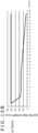
- FIG. 4 illustrates a graph indicating the difference in the effect of the conductive body 30 depending on the path length L and the results of a simulation performed by varying the path length L.
- the horizontal axis of the graph represents the path length L
- the vertical axis represents the intensity of electromagnetic waves (electric field intensity) generated at a measuring point X when the conductive body 30 is connected to the coaxial cable 20.
- the measuring point X is 90 mm from the antenna 10.
- the dashed line in the drawing indicates the electric field intensity at the measuring point X when the conductive body 30 is absent.
- the communication frequency f of the antenna 10 is 2440 MHz
- the path length L is substantially the same as the electrical length Le.
- the conductive body 30 can be electrically connected to the external conductor of the coaxial cable 20 to suppress radiation of electromagnetic waves from the external conductor of the coaxial cable 20 caused by the influence of the antenna 10. This can prevent the electromagnetic waves from affecting the areas around the coaxial cable 20.
- the electronic device 1a may include a plurality of the antennas 10 and a single RF module 41 controlling the radio communication of the antennas 10.
- the coaxial cables 20 connecting the antennas 10 and the RF module 41 approach each other near the RF module 41.
- the electromagnetic waves generated at the coaxial cables 20 may interfere with each other unless a measure is taken.
- conductive bodies 30 are connected to the coaxial cables 20 to prevent interference of nearby coaxial cables 20 in portions of the coaxial cables 20 closer to the RF module 41 than the conductive bodies 30.
- FIG. 5 An electronic device 1b according to a second embodiment of the present invention will now be described with reference to FIG. 5 .
- the shape of the conductive body 30 differs from that of the conductive body 30 according to the first embodiment, but the other components are identical to those according to the first embodiment.
- components corresponding to those according to the first embodiment are denoted by the same reference signs, and descriptions thereof are omitted. This is also the same for the other embodiments described below.
- the conductive body 30 is non-linear and bends at several points to form an overall serpentine shape.
- the conductive body 30 has a meander shape. Even with such a shape, the conductive body 30 can suppress radiation of electromagnetic waves from the coaxial cable 20.
- the path length L of the conductive body 30 is determined such that the electrical length Le approximates (1/4 + n/2) ⁇ .
- the conductive body 30 can suppress radiation of electromagnetic waves from the coaxial cable 20, as in the first embodiment. Furthermore, the meander shape of the conductive body 30 allows the open end O to be disposed not too far from the coaxial cable 20 compared to a linear conductive body 30 having the same path length L. Thus, the conductive body 30 occupies a smaller space in the electronic device 1b.
- the present embodiment differs from the above-described embodiments in that a plurality of conductive bodies are connected to the external conductor of the coaxial cable 20.
- two conductive bodies 30 or conductive bodies 30a and 30b are connected to the external conductor.
- the two conductive bodies 30 have the same path length L and are connected to the coaxial cable 20 at different positions. Since the conductive bodies 30a and 30b have the same path length L, they also have the same electrical length Le. Thus, the conductive bodies 30a and 30b have an advantageous effect on electromagnetic waves in the same frequency band. A plurality of conductive bodies 30 having the same electrical length in this way can suppress the propagation of leakage currents from the antenna 10 more effectively than a single conductive body 30.
- two conductive bodies 30 are connected to the coaxial cable 20.
- three or more conductive bodies 30 may be connected.
- the two conductive bodies 30 extend in opposite directions from the coaxial cable 20.
- the two conductive bodies 30 may be extend in the same direction.
- the two conductive bodies 30 may be disposed on the coaxial cable 20 at the same distance d from the antenna 10 but extend in different directions.
- a plurality of conductive bodies 30 is connected to the external conductor of the coaxial cable 20, as in the third embodiment.
- the conductive bodies 30 have different lengths, unlike the third embodiment.
- a conductive body 30c having a path length La and a conductive body 30d having a path length Lb are connected to the external conductor of the coaxial cable 20.
- the electrical lengths of the conductive bodies 30 are the same as the path lengths.
- the conductive body 30c has an advantageous effect on electromagnetic waves having a wavelength four times larger than the path length La.
- the conductive body 30d has an advantageous effect on electromagnetic waves having a wavelength four times larger than the path length Lb. That is, as a whole, radiation of electromagnetic waves of several different wavelengths are suppressed.
- the antenna 10 of the electronic device 1d according to the present embodiment is, for example, a multi-resonance antenna having multiple resonance frequencies, leakage currents of multiple frequencies propagating from the antenna 10 can be effectively suppressed.
- two conductive bodies 30 are connected to the coaxial cable 20.
- three or more conductive bodies 30 having different electrical lengths may be connected to the coaxial cable 20.
- the two conductive bodies 30 extend in the same directions from the coaxial cable 20.
- the two conductive bodies 30 may be extend in different directions.
- the two conductive bodies 30 may be disposed on the coaxial cable 20 at the same distance d from the antenna 10 but extend in different directions.
- FIG. 8 An electronic device 1e according to a fifth embodiment of the present invention will now be described with reference to FIG. 8 .
- one conductive body 30 having a bent shape similar to that in the second embodiment is provided.
- the conductive body 30 according to the present embodiment bends only once to form an overall L-shape, unlike the second embodiment.
- the conductive body 30 bends toward the antenna 10.
- the position where the conductive body 30 according to the present embodiment bends is denoted as bending point C.
- the conductive body 30 extends in a direction substantially orthogonal to the extending direction of the coaxial cable 20 from the base point B to the bending point C, as illustrated in FIG. 8 .
- the conductive body 30 bends at a substantially right angle at the bending point C and extends in a direction substantially parallel to the extending direction of the coaxial cable 20 from the bending point C to the open end O.
- the path length L is determined in accordance with the communication frequency f of the antenna 10.
- the length L1 corresponds to the linear distance from the coaxial cable 20 to the open end O.
- the inventor varied the length L1 in a stepwise manner while maintaining a constant path length L and varied the connecting points of the conductive body 30 and the coaxial cable 20 (i.e., the distance d from the antenna 10 to the conductive body 30), to study the effect of the conductive body 30.
- FIGS. 9A to 9E illustrate the results of studying the effect of the conductive body 30.
- the drawings illustrate the results of the electric field intensity of the electromagnetic waves radiated from the coaxial cable 20 connected to an antenna 10 having a communication frequency f of 2440 MHz.
- the path length L of the conductive body 30 is a constant value of 30 mm, which corresponds to approximately 1/4 of the wavelength ⁇ corresponding to the communication frequency f.
- the horizontal axis in the drawings represents the distance d from the antenna 10 to the conductive body 30, and the vertical axis represents the electric field intensity indicating the intensity of the electromagnetic waves generated at a measuring point X, as in FIG. 4 .
- the dashed line in the drawing indicates the electric field intensity of the electromagnetic waves generated at the measuring point X when the conductive body 30 is absent.
- FIGS. 9A to 9E indicate the difference in the effect due to a difference in the length L1.
- FIGS. 10A to 10C illustrate the effect of the conductive body 30 when the distance d was constant and the length L1 was varied.
- FIGS. 10A , 10B , and 10C illustrate the electric field intensity at the measuring point X when the distance d was 50 mm, 75 mm, and 90 mm, respectively.
- the conductive body 30 was not effective when the length L1 was 1 mm, regardless of the distance d, but when the length L1 was increased to 3 mm, the effect of the conductive body 30 was suddenly enhanced.
- the electric field intensity decreased due to the effect of the conductive body 30 until the length L1 reached 5 mm and then remained substantially the same after that. Consequently, even when the conductive body 30 is bent midway, the open end is preferably disposed at least 3 mm from the coaxial cable 20, more desirably, at least 5 mm.
- the effect of the conductive body 30 varied also depending on the distance d.
- the shape of the conductive body 30 and the connecting position to the coaxial cable 20 can be appropriately adjusted to increase the effect of the conductive body 30 on suppressing electromagnetic waves.
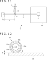
- FIGS. 11 and 12 An electronic device 1f according to a sixth embodiment of the present invention will now be described with reference to FIGS. 11 and 12 .
- the covering of the coaxial cable 20 is removed and the conductive body 30 is directly connected to the exposed external conductor, to electrically couple the conductive body 30 and the external conductor of the coaxial cable 20.
- the conductive body 30 is disposed outside the covering and near the coaxial cable 20, without removing the covering of the coaxial cable 20. In such a case, the conductive body 30 does not establish a direct electrical connection with the coaxial cable 20 but is electrically coupled to the external conductor through capacitance coupling. In this way, radiation of electromagnetic waves from the coaxial cable 20 can be prevented even when the conductive body 30 is not in a direct electrical connection with the external conductor of the coaxial cable 20.
- FIG. 11 illustrates the overall internal configuration of the electronic device 1f according to the present embodiment.
- FIG. 12 is an enlarged cross-sectional view of the area in which the conductive body 30 is disposed taken along a direction orthogonal to the extending direction of the coaxial cable 20.
- the coaxial cable 20 includes a signal line 20d passing through the center, a dielectric body 20c disposed between the signal line 20d and an external conductor 20b, and a covering 20a disposed around the external conductor 20b.
- the covering 20a of the coaxial cable 20 is not removed, and the coaxial cable 20 and the conductive body 30 overlaps each other in plan view.
- the conductive body 30 establishes capacitance coupling with the external conductor 20b of the coaxial cable 20 across the covering 20a.
- the conductive body 30 is in contact with the covering 20a.
- the conductive body 30 may be disposed apart from the covering 20a.
- the effect of the conductive body 30 on suppressing electromagnetic waves is enhanced when the electrical length Le is within the range of (1/8 + n/2) ⁇ ⁇ Le d (3/8 + n/2)X, where n is an integer larger than or equal to zero.
- the width W in the lateral direction (a direction parallel to the extending direction of the coaxial cable 20) of the conductive body 30 should be large enough to establish capacitance coupling of the conductive body 30 and the external conductor 20b.
- FIG. 14 illustrates a graph indicating the difference in the effect of the conductive body 30 depending on the width W.
- the vertical axis represents the electric field intensity at the measuring point X
- the horizontal axis represents the width W of the conductive body 30.
- the dashed line indicates the electric field intensity when the conductive body 30 is absent.
- the width W of the conductive body 30 is preferably 2 mm or more, more preferably, 6 mm or more.
- the width W of the conductive body 30 is constant.
- the width W of the conductive body 30 may not be constant.
- the width W of the conductive body 30 should be large at the position overlapping with the coaxial cable 20, as described above.
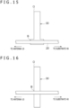
- the width W of the conductive body 30 at the position overlapping with the coaxial cable 20 may be large, and the width W of other portions may be relatively small.
- FIG. 15 illustrates the shape of such a conductive body 30 according to a modification.
- an end of the conductive body 30 opposite the open end O is electrically coupled to the coaxial cable 20.
- a midway position of the conductive body 30 may be electrically coupled to the coaxial cable 20.
- FIG. 16 illustrates an example position of the conductive body 30 in such a case.
- the external conductor 20b of the coaxial cable 20 and the conductive body 30 establish capacitance coupling at a position overlapping in plan view.
- the end portion opposite the open end O also is effective in suppressing electromagnetic waves having a wavelength corresponding to the length of the end portion.
- a cable connected to the ground of the substrate 40 can function as the conductive body 30 because the conductive body 30 is not electrically connected to the external conductor 20b of the coaxial cable 20.
- FIG. 17 illustrates an example position of the conductive body 30 in such a case.
- the conductive body 30 is a flexible cable.
- the end of the conductive body 30 opposite the open end O is connected to a connecter provided on the substrate 40.
- the end of the conductive body 30 opposite the open end O is connected to the ground of the substrate 40 connected to the coaxial cable 20.
- the open end O of the conductive body 30, which is folded once, is connected to a circuit board in a peripheral device 50.
- the flexible cable functioning as the conductive body 30 connects the electronic circuits in the substrate 40 and the peripheral device 50.
- the ground of the circuit board of the peripheral device 50 is electrically separated from the ground of the substrate 40.
- the open end O of the conductive body 30 is not directly connected to the ground of the substrate 40 connected to the coaxial cable 20 and thus prevents propagation of electromagnetic waves having a wavelength ⁇ corresponding to the path length L, in view of the coaxial cable 20.
- a cable overlapping the coaxial cable 20 functions as the conductive body 30 if one end of the cable functions as an open end O not directly connected to the ground connected to the coaxial cable 20.
- the end of the conductive body 30 opposite the open end O may be electrically connected to the ground connected to the coaxial cable 20.
- the antenna 10 performs radio communication in accordance with a wireless LAN standard or a Bluetooth standard.
- the conductive body may be connected to a coaxial cable connected to an antenna of any other type besides those described above.
- the conductive body may be provided in any number or shape besides those described above to achieve similar advantageous effects.
- some or all conductive bodies 30 may have a meander shape.
- multiple conductive bodies 30 electrically coupled to the coaxial cable 20 through capacitance coupling may be provided, and the conductive bodies 30 may have an L-shape or a meander shape.
Claims (9)
- Elektronische Vorrichtung (1), die Folgendes umfasst:ein Koaxialkabel (20), das mit einer Antenne (10) verbunden ist; undwenigstens einen leitfähigen Körper, der eine streifenartige Form aufweist und elektrisch an einen äußeren Leiter der Koaxialkabels gekoppelt ist, wobei ein Ende des leitfähigen Körpers (O) nicht direkt mit Masse verbunden ist, die mit dem Koaxialkabel verbunden ist, wobei sich der wenigstens eine leitfähige Körper an einer Position befindet, die mit dem Koaxialkabel in einer Draufsicht überlappt, und über eine Abdeckung des Koaxialkabels durch kapazitive Kopplung elektrisch an den äußeren Leiter gekoppelt ist, und wobeisich der wenigstens eine leitfähige Körper in einer Richtung, die im Wesentlichen zu der Erstreckungsrichtung des Koaxialkabels senkrecht ist, an einer Position, an der der wenigstens eine leitfähige Körper an das Koaxialkabel gekoppelt ist, erstreckt.
- Elektronische Vorrichtung nach Anspruch 1, wobei
sich eine elektrische Länge des wenigstens einen leitfähigen Körpers von einer Position, an der der wenigstens eine leitfähige Körper an den externen Leiter gekoppelt ist, bis zu dem einen Ende in einem Bereich von (1/8 + n/2)λ bis einschließlich (3/8 + n/2)λ befindet, wobei λ eine Wellenlänge der elektromagnetischen Wellen ist, die einer Kommunikationsfrequenz der Antenne entspricht, und n eine ganze Zahl größer oder gleich null ist. - Elektronische Vorrichtung nach Anspruch 1, wobei
eine Breite des wenigstens einen leitfähigen Körpers an der Position, an der der wenigstens eine leitfähige Körper mit dem Koaxialkabel überlappt, entlang einer Erstreckungsrichtung des Koaxialkabels 2 mm oder größer ist. - Elektronische Vorrichtung nach Anspruch 1 oder 3, wobei
der wenigstens eine leitfähige Körper ein Kabel enthält, wobei ein dem einen Ende (O) gegenüberliegendes Ende direkt mit Masse verbunden ist, die mit dem Koaxialkabel verbunden ist. - Elektronische Vorrichtung nach einem der Ansprüche 1 bis 4, wobei der wenigstens eine leitfähige Körper eine lineare Form aufweist.
- Elektronische Vorrichtung nach einem der Ansprüche 1 bis 4, wobei der wenigstens eine leitfähige Körper in der Mitte eine gebogene Form aufweist.
- Elektronische Vorrichtung nach einem der Ansprüche 1 bis 6, wobei der wenigstens eine leitfähige Körper mehrere leitfähige Körper umfasst, wovon jeder eine streifenartige Form aufweist und elektrisch an den äußeren Leiter des Koaxialkabels gekoppelt ist.
- Elektronische Vorrichtung nach einem der Ansprüche 1 bis 7, wobei das eine Ende (O) des wenigstens einen leitfähigen Körpers in einem Abstand von 3 mm oder mehr von dem Koaxialkabel angeordnet ist.
- Elektronische Vorrichtung nach einem der Ansprüche 1 bis 8, wobei eine Länge des Koaxialkabels zwischen einer Position, an der der wenigstens eine leitfähige Körper an das Koaxialkabel gekoppelt ist, und der Antenne größer als ein Viertel der Wellenlänge der elektromagnetischen Wellen ist, die einer Kommunikationsfrequenz der Antenne entsprechen.
Applications Claiming Priority (1)
| Application Number | Priority Date | Filing Date | Title |
|---|---|---|---|
| PCT/JP2017/005337 WO2018150468A1 (ja) | 2017-02-14 | 2017-02-14 | 電子機器 |
Publications (3)
| Publication Number | Publication Date |
|---|---|
| EP3584880A1 EP3584880A1 (de) | 2019-12-25 |
| EP3584880A4 EP3584880A4 (de) | 2020-10-28 |
| EP3584880B1 true EP3584880B1 (de) | 2023-03-29 |
Family
ID=63170539
Family Applications (1)
| Application Number | Title | Priority Date | Filing Date |
|---|---|---|---|
| EP17896773.3A Active EP3584880B1 (de) | 2017-02-14 | 2017-02-14 | Elektronische vorrichtung |
Country Status (5)
| Country | Link |
|---|---|
| US (1) | US11171398B2 (de) |
| EP (1) | EP3584880B1 (de) |
| JP (1) | JP6887483B2 (de) |
| CN (1) | CN110268578A (de) |
| WO (1) | WO2018150468A1 (de) |
Families Citing this family (3)
| Publication number | Priority date | Publication date | Assignee | Title |
|---|---|---|---|---|
| DE69941305D1 (de) | 1998-11-20 | 2009-10-01 | Intuitive Surgical Inc | System für Durchführung herzchirurgischer Eingriffe ohne Kardioplegie |
| US6659939B2 (en) | 1998-11-20 | 2003-12-09 | Intuitive Surgical, Inc. | Cooperative minimally invasive telesurgical system |
| EP1575439B1 (de) | 2002-12-06 | 2012-04-04 | Intuitive Surgical, Inc. | Flexibles gelenk für ein operationsinstrument |
Family Cites Families (15)
| Publication number | Priority date | Publication date | Assignee | Title |
|---|---|---|---|---|
| JPS6199402A (ja) * | 1984-10-19 | 1986-05-17 | Mitsubishi Electric Corp | インピ−ダンス整合器 |
| JPS62177106A (ja) | 1986-01-30 | 1987-08-04 | Kobe Steel Ltd | 複合弁体の製造方法 |
| JPH0314809Y2 (de) * | 1986-04-28 | 1991-04-02 | ||
| JPH07245518A (ja) * | 1994-03-07 | 1995-09-19 | Harada Ind Co Ltd | 無線通信用ダイバシティアンテナ |
| JP3165653B2 (ja) * | 1997-02-20 | 2001-05-14 | 日本アンテナ株式会社 | 八木宇田アンテナ |
| JP3065989B2 (ja) * | 1998-05-25 | 2000-07-17 | 日本アンテナ株式会社 | 整合方法および整合装置 |
| JP3622959B2 (ja) * | 2001-11-09 | 2005-02-23 | 日立電線株式会社 | 平板アンテナの製造方法 |
| JP2004343193A (ja) | 2003-05-13 | 2004-12-02 | Nippon Antenna Co Ltd | アンテナ装置 |
| JP2005191792A (ja) * | 2003-12-25 | 2005-07-14 | Matsushita Electric Ind Co Ltd | アンテナ装置及びそれを用いた無線通信装置 |
| JP5371792B2 (ja) | 2010-01-05 | 2013-12-18 | 中国電力株式会社 | 避雷装置 |
| JP5323271B2 (ja) * | 2011-04-11 | 2013-10-23 | パナソニック株式会社 | アンテナ装置及び無線通信装置 |
| EP2710668B1 (de) | 2011-05-02 | 2019-07-31 | CommScope Technologies LLC | Dreipoliges antennenelement und gruppenantenne |
| WO2013047033A1 (ja) * | 2011-09-26 | 2013-04-04 | 株式会社フジクラ | アンテナ装置及びアンテナの実装方法 |
| US9466888B2 (en) * | 2013-08-26 | 2016-10-11 | Honeywell International Inc. | Suppressing modes in an antenna feed including a coaxial waveguide |
| JP2015073239A (ja) * | 2013-10-04 | 2015-04-16 | 日立金属株式会社 | アンテナ装置及び無線通信機器 |
-
2017
- 2017-02-14 JP JP2019500071A patent/JP6887483B2/ja active Active
- 2017-02-14 CN CN201780085886.6A patent/CN110268578A/zh active Pending
- 2017-02-14 EP EP17896773.3A patent/EP3584880B1/de active Active
- 2017-02-14 WO PCT/JP2017/005337 patent/WO2018150468A1/ja unknown
- 2017-02-14 US US16/482,183 patent/US11171398B2/en active Active
Also Published As
| Publication number | Publication date |
|---|---|
| EP3584880A1 (de) | 2019-12-25 |
| US11171398B2 (en) | 2021-11-09 |
| JP6887483B2 (ja) | 2021-06-16 |
| WO2018150468A1 (ja) | 2018-08-23 |
| US20200044302A1 (en) | 2020-02-06 |
| CN110268578A (zh) | 2019-09-20 |
| JPWO2018150468A1 (ja) | 2019-12-19 |
| EP3584880A4 (de) | 2020-10-28 |
Similar Documents
| Publication | Publication Date | Title |
|---|---|---|
| US8836588B2 (en) | Antenna device and electronic apparatus including antenna device | |
| TWI568076B (zh) | 天線結構 | |
| US8854266B2 (en) | Antenna isolation elements | |
| US8963794B2 (en) | Distributed loop antennas | |
| US9368873B2 (en) | Triple-band antenna and method of manufacture | |
| US20120038520A1 (en) | Omni-directional antenna system for wireless communication | |
| US20130113671A1 (en) | Slot antenna | |
| US20160241288A1 (en) | Wireless communication apparatus and electronic apparatus | |
| CN106605335B (zh) | 天线以及电气设备 | |
| US20140009359A1 (en) | Wideband monopole antenna and electronic device | |
| EP3584880B1 (de) | Elektronische vorrichtung | |
| Lu et al. | Planar small-size eight-band LTE/WWAN monopole antenna for tablet computers | |
| US10965005B2 (en) | Communication device and antenna structure | |
| US20110043421A1 (en) | Portable electronic device and antenna thereof | |
| TWI538310B (zh) | 雙頻印刷式的單極天線 | |
| US7598912B2 (en) | Planar antenna structure | |
| CN112436272B (zh) | 天线装置及电子设备 | |
| JP6386403B2 (ja) | アンテナ装置 | |
| US9812769B2 (en) | Antenna apparatus | |
| JP2016225846A (ja) | アンテナ装置 | |
| US20110181474A1 (en) | Miniature three-dimensional antenna | |
| US10847891B2 (en) | Antenna device and wireless communication apparatus | |
| KR102003955B1 (ko) | 소형 광대역 다이폴 안테나 | |
| KR101520223B1 (ko) | 전송선 로드 안테나 모듈 | |
| EP4290683A1 (de) | Antennenvorrichtung und kommunikationsvorrichtung |
Legal Events
| Date | Code | Title | Description |
|---|---|---|---|
| STAA | Information on the status of an ep patent application or granted ep patent |
Free format text: STATUS: THE INTERNATIONAL PUBLICATION HAS BEEN MADE |
|
| PUAI | Public reference made under article 153(3) epc to a published international application that has entered the european phase |
Free format text: ORIGINAL CODE: 0009012 |
|
| STAA | Information on the status of an ep patent application or granted ep patent |
Free format text: STATUS: REQUEST FOR EXAMINATION WAS MADE |
|
| 17P | Request for examination filed |
Effective date: 20190807 |
|
| AK | Designated contracting states |
Kind code of ref document: A1 Designated state(s): AL AT BE BG CH CY CZ DE DK EE ES FI FR GB GR HR HU IE IS IT LI LT LU LV MC MK MT NL NO PL PT RO RS SE SI SK SM TR |
|
| AX | Request for extension of the european patent |
Extension state: BA ME |
|
| DAV | Request for validation of the european patent (deleted) | ||
| DAX | Request for extension of the european patent (deleted) | ||
| A4 | Supplementary search report drawn up and despatched |
Effective date: 20200928 |
|
| RIC1 | Information provided on ipc code assigned before grant |
Ipc: H01P 3/06 20060101ALI20200922BHEP Ipc: H01P 5/10 20060101ALI20200922BHEP Ipc: H01Q 1/52 20060101ALI20200922BHEP Ipc: H01Q 1/50 20060101AFI20200922BHEP |
|
| STAA | Information on the status of an ep patent application or granted ep patent |
Free format text: STATUS: EXAMINATION IS IN PROGRESS |
|
| 17Q | First examination report despatched |
Effective date: 20210730 |
|
| STAA | Information on the status of an ep patent application or granted ep patent |
Free format text: STATUS: EXAMINATION IS IN PROGRESS |
|
| GRAP | Despatch of communication of intention to grant a patent |
Free format text: ORIGINAL CODE: EPIDOSNIGR1 |
|
| STAA | Information on the status of an ep patent application or granted ep patent |
Free format text: STATUS: GRANT OF PATENT IS INTENDED |
|
| INTG | Intention to grant announced |
Effective date: 20221004 |
|
| GRAS | Grant fee paid |
Free format text: ORIGINAL CODE: EPIDOSNIGR3 |
|
| GRAA | (expected) grant |
Free format text: ORIGINAL CODE: 0009210 |
|
| STAA | Information on the status of an ep patent application or granted ep patent |
Free format text: STATUS: THE PATENT HAS BEEN GRANTED |
|
| AK | Designated contracting states |
Kind code of ref document: B1 Designated state(s): AL AT BE BG CH CY CZ DE DK EE ES FI FR GB GR HR HU IE IS IT LI LT LU LV MC MK MT NL NO PL PT RO RS SE SI SK SM TR |
|
| REG | Reference to a national code |
Ref country code: CH Ref legal event code: EP |
|
| REG | Reference to a national code |
Ref country code: DE Ref legal event code: R096 Ref document number: 602017067325 Country of ref document: DE |
|
| REG | Reference to a national code |
Ref country code: AT Ref legal event code: REF Ref document number: 1557318 Country of ref document: AT Kind code of ref document: T Effective date: 20230415 |
|
| REG | Reference to a national code |
Ref country code: IE Ref legal event code: FG4D |
|
| P01 | Opt-out of the competence of the unified patent court (upc) registered |
Effective date: 20230519 |
|
| REG | Reference to a national code |
Ref country code: LT Ref legal event code: MG9D |
|
| PG25 | Lapsed in a contracting state [announced via postgrant information from national office to epo] |
Ref country code: RS Free format text: LAPSE BECAUSE OF FAILURE TO SUBMIT A TRANSLATION OF THE DESCRIPTION OR TO PAY THE FEE WITHIN THE PRESCRIBED TIME-LIMIT Effective date: 20230329 Ref country code: NO Free format text: LAPSE BECAUSE OF FAILURE TO SUBMIT A TRANSLATION OF THE DESCRIPTION OR TO PAY THE FEE WITHIN THE PRESCRIBED TIME-LIMIT Effective date: 20230629 Ref country code: LV Free format text: LAPSE BECAUSE OF FAILURE TO SUBMIT A TRANSLATION OF THE DESCRIPTION OR TO PAY THE FEE WITHIN THE PRESCRIBED TIME-LIMIT Effective date: 20230329 Ref country code: LT Free format text: LAPSE BECAUSE OF FAILURE TO SUBMIT A TRANSLATION OF THE DESCRIPTION OR TO PAY THE FEE WITHIN THE PRESCRIBED TIME-LIMIT Effective date: 20230329 Ref country code: HR Free format text: LAPSE BECAUSE OF FAILURE TO SUBMIT A TRANSLATION OF THE DESCRIPTION OR TO PAY THE FEE WITHIN THE PRESCRIBED TIME-LIMIT Effective date: 20230329 |
|
| REG | Reference to a national code |
Ref country code: NL Ref legal event code: MP Effective date: 20230329 |
|
| REG | Reference to a national code |
Ref country code: AT Ref legal event code: MK05 Ref document number: 1557318 Country of ref document: AT Kind code of ref document: T Effective date: 20230329 |
|
| PG25 | Lapsed in a contracting state [announced via postgrant information from national office to epo] |
Ref country code: SE Free format text: LAPSE BECAUSE OF FAILURE TO SUBMIT A TRANSLATION OF THE DESCRIPTION OR TO PAY THE FEE WITHIN THE PRESCRIBED TIME-LIMIT Effective date: 20230329 Ref country code: NL Free format text: LAPSE BECAUSE OF FAILURE TO SUBMIT A TRANSLATION OF THE DESCRIPTION OR TO PAY THE FEE WITHIN THE PRESCRIBED TIME-LIMIT Effective date: 20230329 Ref country code: GR Free format text: LAPSE BECAUSE OF FAILURE TO SUBMIT A TRANSLATION OF THE DESCRIPTION OR TO PAY THE FEE WITHIN THE PRESCRIBED TIME-LIMIT Effective date: 20230630 Ref country code: FI Free format text: LAPSE BECAUSE OF FAILURE TO SUBMIT A TRANSLATION OF THE DESCRIPTION OR TO PAY THE FEE WITHIN THE PRESCRIBED TIME-LIMIT Effective date: 20230329 |
|
| PG25 | Lapsed in a contracting state [announced via postgrant information from national office to epo] |
Ref country code: SM Free format text: LAPSE BECAUSE OF FAILURE TO SUBMIT A TRANSLATION OF THE DESCRIPTION OR TO PAY THE FEE WITHIN THE PRESCRIBED TIME-LIMIT Effective date: 20230329 Ref country code: RO Free format text: LAPSE BECAUSE OF FAILURE TO SUBMIT A TRANSLATION OF THE DESCRIPTION OR TO PAY THE FEE WITHIN THE PRESCRIBED TIME-LIMIT Effective date: 20230329 Ref country code: PT Free format text: LAPSE BECAUSE OF FAILURE TO SUBMIT A TRANSLATION OF THE DESCRIPTION OR TO PAY THE FEE WITHIN THE PRESCRIBED TIME-LIMIT Effective date: 20230731 Ref country code: ES Free format text: LAPSE BECAUSE OF FAILURE TO SUBMIT A TRANSLATION OF THE DESCRIPTION OR TO PAY THE FEE WITHIN THE PRESCRIBED TIME-LIMIT Effective date: 20230329 Ref country code: EE Free format text: LAPSE BECAUSE OF FAILURE TO SUBMIT A TRANSLATION OF THE DESCRIPTION OR TO PAY THE FEE WITHIN THE PRESCRIBED TIME-LIMIT Effective date: 20230329 Ref country code: AT Free format text: LAPSE BECAUSE OF FAILURE TO SUBMIT A TRANSLATION OF THE DESCRIPTION OR TO PAY THE FEE WITHIN THE PRESCRIBED TIME-LIMIT Effective date: 20230329 |
|
| PG25 | Lapsed in a contracting state [announced via postgrant information from national office to epo] |
Ref country code: SK Free format text: LAPSE BECAUSE OF FAILURE TO SUBMIT A TRANSLATION OF THE DESCRIPTION OR TO PAY THE FEE WITHIN THE PRESCRIBED TIME-LIMIT Effective date: 20230329 Ref country code: PL Free format text: LAPSE BECAUSE OF FAILURE TO SUBMIT A TRANSLATION OF THE DESCRIPTION OR TO PAY THE FEE WITHIN THE PRESCRIBED TIME-LIMIT Effective date: 20230329 Ref country code: IS Free format text: LAPSE BECAUSE OF FAILURE TO SUBMIT A TRANSLATION OF THE DESCRIPTION OR TO PAY THE FEE WITHIN THE PRESCRIBED TIME-LIMIT Effective date: 20230729 |
|
| REG | Reference to a national code |
Ref country code: DE Ref legal event code: R097 Ref document number: 602017067325 Country of ref document: DE |
|
| PG25 | Lapsed in a contracting state [announced via postgrant information from national office to epo] |
Ref country code: DK Free format text: LAPSE BECAUSE OF FAILURE TO SUBMIT A TRANSLATION OF THE DESCRIPTION OR TO PAY THE FEE WITHIN THE PRESCRIBED TIME-LIMIT Effective date: 20230329 Ref country code: CZ Free format text: LAPSE BECAUSE OF FAILURE TO SUBMIT A TRANSLATION OF THE DESCRIPTION OR TO PAY THE FEE WITHIN THE PRESCRIBED TIME-LIMIT Effective date: 20230329 |
|
| PLBE | No opposition filed within time limit |
Free format text: ORIGINAL CODE: 0009261 |
|
| STAA | Information on the status of an ep patent application or granted ep patent |
Free format text: STATUS: NO OPPOSITION FILED WITHIN TIME LIMIT |
|
| 26N | No opposition filed |
Effective date: 20240103 |