EP3584665B1 - Flüssigkeitsmischvorrichtung mit elektronischer steuerung mit hoher dynamischer regulierung und betriebsverfahren dafür - Google Patents
Flüssigkeitsmischvorrichtung mit elektronischer steuerung mit hoher dynamischer regulierung und betriebsverfahren dafür Download PDFInfo
- Publication number
- EP3584665B1 EP3584665B1 EP19179644.0A EP19179644A EP3584665B1 EP 3584665 B1 EP3584665 B1 EP 3584665B1 EP 19179644 A EP19179644 A EP 19179644A EP 3584665 B1 EP3584665 B1 EP 3584665B1
- Authority
- EP
- European Patent Office
- Prior art keywords
- flow
- liquid
- temperature
- mixing device
- electronic control
- Prior art date
- Legal status (The legal status is an assumption and is not a legal conclusion. Google has not performed a legal analysis and makes no representation as to the accuracy of the status listed.)
- Active
Links
Images


Classifications
-
- B—PERFORMING OPERATIONS; TRANSPORTING
- B01—PHYSICAL OR CHEMICAL PROCESSES OR APPARATUS IN GENERAL
- B01F—MIXING, e.g. DISSOLVING, EMULSIFYING OR DISPERSING
- B01F23/00—Mixing according to the phases to be mixed, e.g. dispersing or emulsifying
- B01F23/40—Mixing liquids with liquids; Emulsifying
- B01F23/49—Mixing systems, i.e. flow charts or diagrams
-
- G—PHYSICS
- G05—CONTROLLING; REGULATING
- G05D—SYSTEMS FOR CONTROLLING OR REGULATING NON-ELECTRIC VARIABLES
- G05D23/00—Control of temperature
- G05D23/01—Control of temperature without auxiliary power
- G05D23/13—Control of temperature without auxiliary power by varying the mixing ratio of two fluids having different temperatures
- G05D23/1393—Control of temperature without auxiliary power by varying the mixing ratio of two fluids having different temperatures characterised by the use of electric means
-
- B—PERFORMING OPERATIONS; TRANSPORTING
- B01—PHYSICAL OR CHEMICAL PROCESSES OR APPARATUS IN GENERAL
- B01F—MIXING, e.g. DISSOLVING, EMULSIFYING OR DISPERSING
- B01F35/00—Accessories for mixers; Auxiliary operations or auxiliary devices; Parts or details of general application
- B01F35/20—Measuring; Control or regulation
- B01F35/21—Measuring
- B01F35/211—Measuring of the operational parameters
- B01F35/2111—Flow rate
-
- B—PERFORMING OPERATIONS; TRANSPORTING
- B01—PHYSICAL OR CHEMICAL PROCESSES OR APPARATUS IN GENERAL
- B01F—MIXING, e.g. DISSOLVING, EMULSIFYING OR DISPERSING
- B01F35/00—Accessories for mixers; Auxiliary operations or auxiliary devices; Parts or details of general application
- B01F35/20—Measuring; Control or regulation
- B01F35/21—Measuring
- B01F35/211—Measuring of the operational parameters
- B01F35/2115—Temperature
-
- B—PERFORMING OPERATIONS; TRANSPORTING
- B01—PHYSICAL OR CHEMICAL PROCESSES OR APPARATUS IN GENERAL
- B01F—MIXING, e.g. DISSOLVING, EMULSIFYING OR DISPERSING
- B01F35/00—Accessories for mixers; Auxiliary operations or auxiliary devices; Parts or details of general application
- B01F35/20—Measuring; Control or regulation
- B01F35/22—Control or regulation
- B01F35/221—Control or regulation of operational parameters, e.g. level of material in the mixer, temperature or pressure
- B01F35/2211—Amount of delivered fluid during a period
-
- E—FIXED CONSTRUCTIONS
- E03—WATER SUPPLY; SEWERAGE
- E03C—DOMESTIC PLUMBING INSTALLATIONS FOR FRESH WATER OR WASTE WATER; SINKS
- E03C1/00—Domestic plumbing installations for fresh water or waste water; Sinks
- E03C1/02—Plumbing installations for fresh water
- E03C1/04—Water-basin installations specially adapted to wash-basins or baths
- E03C1/044—Water-basin installations specially adapted to wash-basins or baths having a heating or cooling apparatus in the supply line
-
- F—MECHANICAL ENGINEERING; LIGHTING; HEATING; WEAPONS; BLASTING
- F24—HEATING; RANGES; VENTILATING
- F24D—DOMESTIC- OR SPACE-HEATING SYSTEMS, e.g. CENTRAL HEATING SYSTEMS; DOMESTIC HOT-WATER SUPPLY SYSTEMS; ELEMENTS OR COMPONENTS THEREFOR
- F24D17/00—Domestic hot-water supply systems
-
- F—MECHANICAL ENGINEERING; LIGHTING; HEATING; WEAPONS; BLASTING
- F24—HEATING; RANGES; VENTILATING
- F24D—DOMESTIC- OR SPACE-HEATING SYSTEMS, e.g. CENTRAL HEATING SYSTEMS; DOMESTIC HOT-WATER SUPPLY SYSTEMS; ELEMENTS OR COMPONENTS THEREFOR
- F24D19/00—Details
- F24D19/10—Arrangement or mounting of control or safety devices
- F24D19/1006—Arrangement or mounting of control or safety devices for water heating systems
- F24D19/1051—Arrangement or mounting of control or safety devices for water heating systems for domestic hot water
-
- G—PHYSICS
- G01—MEASURING; TESTING
- G01F—MEASURING VOLUME, VOLUME FLOW, MASS FLOW OR LIQUID LEVEL; METERING BY VOLUME
- G01F1/00—Measuring the volume flow or mass flow of fluid or fluent solid material wherein the fluid passes through a meter in a continuous flow
- G01F1/66—Measuring the volume flow or mass flow of fluid or fluent solid material wherein the fluid passes through a meter in a continuous flow by measuring frequency, phase shift or propagation time of electromagnetic or other waves, e.g. using ultrasonic flowmeters
-
- G—PHYSICS
- G01—MEASURING; TESTING
- G01F—MEASURING VOLUME, VOLUME FLOW, MASS FLOW OR LIQUID LEVEL; METERING BY VOLUME
- G01F1/00—Measuring the volume flow or mass flow of fluid or fluent solid material wherein the fluid passes through a meter in a continuous flow
- G01F1/66—Measuring the volume flow or mass flow of fluid or fluent solid material wherein the fluid passes through a meter in a continuous flow by measuring frequency, phase shift or propagation time of electromagnetic or other waves, e.g. using ultrasonic flowmeters
- G01F1/662—Constructional details
-
- G—PHYSICS
- G01—MEASURING; TESTING
- G01F—MEASURING VOLUME, VOLUME FLOW, MASS FLOW OR LIQUID LEVEL; METERING BY VOLUME
- G01F1/00—Measuring the volume flow or mass flow of fluid or fluent solid material wherein the fluid passes through a meter in a continuous flow
- G01F1/66—Measuring the volume flow or mass flow of fluid or fluent solid material wherein the fluid passes through a meter in a continuous flow by measuring frequency, phase shift or propagation time of electromagnetic or other waves, e.g. using ultrasonic flowmeters
- G01F1/667—Arrangements of transducers for ultrasonic flowmeters; Circuits for operating ultrasonic flowmeters
- G01F1/668—Compensating or correcting for variations in velocity of sound
-
- G—PHYSICS
- G01—MEASURING; TESTING
- G01F—MEASURING VOLUME, VOLUME FLOW, MASS FLOW OR LIQUID LEVEL; METERING BY VOLUME
- G01F15/00—Details of, or accessories for, apparatus of groups G01F1/00 - G01F13/00 insofar as such details or appliances are not adapted to particular types of such apparatus
- G01F15/001—Means for regulating or setting the meter for a predetermined quantity
- G01F15/003—Means for regulating or setting the meter for a predetermined quantity using electromagnetic, electric or electronic means
-
- G—PHYSICS
- G01—MEASURING; TESTING
- G01F—MEASURING VOLUME, VOLUME FLOW, MASS FLOW OR LIQUID LEVEL; METERING BY VOLUME
- G01F15/00—Details of, or accessories for, apparatus of groups G01F1/00 - G01F13/00 insofar as such details or appliances are not adapted to particular types of such apparatus
- G01F15/02—Compensating or correcting for variations in pressure, density or temperature
-
- G—PHYSICS
- G05—CONTROLLING; REGULATING
- G05D—SYSTEMS FOR CONTROLLING OR REGULATING NON-ELECTRIC VARIABLES
- G05D23/00—Control of temperature
- G05D23/19—Control of temperature characterised by the use of electric means
- G05D23/1927—Control of temperature characterised by the use of electric means using a plurality of sensors
- G05D23/193—Control of temperature characterised by the use of electric means using a plurality of sensors sensing the temperaure in different places in thermal relationship with one or more spaces
- G05D23/1931—Control of temperature characterised by the use of electric means using a plurality of sensors sensing the temperaure in different places in thermal relationship with one or more spaces to control the temperature of one space
-
- G—PHYSICS
- G05—CONTROLLING; REGULATING
- G05D—SYSTEMS FOR CONTROLLING OR REGULATING NON-ELECTRIC VARIABLES
- G05D7/00—Control of flow
- G05D7/06—Control of flow characterised by the use of electric means
- G05D7/0617—Control of flow characterised by the use of electric means specially adapted for fluid materials
- G05D7/0629—Control of flow characterised by the use of electric means specially adapted for fluid materials characterised by the type of regulator means
- G05D7/0635—Control of flow characterised by the use of electric means specially adapted for fluid materials characterised by the type of regulator means by action on throttling means
- G05D7/0641—Control of flow characterised by the use of electric means specially adapted for fluid materials characterised by the type of regulator means by action on throttling means using a plurality of throttling means
- G05D7/0652—Control of flow characterised by the use of electric means specially adapted for fluid materials characterised by the type of regulator means by action on throttling means using a plurality of throttling means the plurality of throttling means being arranged in parallel
-
- E—FIXED CONSTRUCTIONS
- E03—WATER SUPPLY; SEWERAGE
- E03C—DOMESTIC PLUMBING INSTALLATIONS FOR FRESH WATER OR WASTE WATER; SINKS
- E03C1/00—Domestic plumbing installations for fresh water or waste water; Sinks
- E03C1/02—Plumbing installations for fresh water
- E03C1/04—Water-basin installations specially adapted to wash-basins or baths
- E03C2001/0418—Water-basin installations specially adapted to wash-basins or baths having temperature indicating means
-
- G—PHYSICS
- G01—MEASURING; TESTING
- G01F—MEASURING VOLUME, VOLUME FLOW, MASS FLOW OR LIQUID LEVEL; METERING BY VOLUME
- G01F15/00—Details of, or accessories for, apparatus of groups G01F1/00 - G01F13/00 insofar as such details or appliances are not adapted to particular types of such apparatus
- G01F15/005—Valves
-
- Y—GENERAL TAGGING OF NEW TECHNOLOGICAL DEVELOPMENTS; GENERAL TAGGING OF CROSS-SECTIONAL TECHNOLOGIES SPANNING OVER SEVERAL SECTIONS OF THE IPC; TECHNICAL SUBJECTS COVERED BY FORMER USPC CROSS-REFERENCE ART COLLECTIONS [XRACs] AND DIGESTS
- Y10—TECHNICAL SUBJECTS COVERED BY FORMER USPC
- Y10T—TECHNICAL SUBJECTS COVERED BY FORMER US CLASSIFICATION
- Y10T137/00—Fluid handling
- Y10T137/2496—Self-proportioning or correlating systems
- Y10T137/2499—Mixture condition maintaining or sensing
-
- Y—GENERAL TAGGING OF NEW TECHNOLOGICAL DEVELOPMENTS; GENERAL TAGGING OF CROSS-SECTIONAL TECHNOLOGIES SPANNING OVER SEVERAL SECTIONS OF THE IPC; TECHNICAL SUBJECTS COVERED BY FORMER USPC CROSS-REFERENCE ART COLLECTIONS [XRACs] AND DIGESTS
- Y10—TECHNICAL SUBJECTS COVERED BY FORMER USPC
- Y10T—TECHNICAL SUBJECTS COVERED BY FORMER US CLASSIFICATION
- Y10T137/00—Fluid handling
- Y10T137/7722—Line condition change responsive valves
- Y10T137/7737—Thermal responsive
Definitions
- the present invention relates to an operating method of a liquid mixing device with electronic control of regulation of flow and also relates to a liquid mixing device which has a control system and electronic regulation.
- Extreme conditions may even occur, such as the bursting or cut-off of a supply line, with the sudden interruption of the supply of the corresponding supply line, having in a very short time interval the passage of mixed water at a desired comfort temperature to have exclusively uninterrupted supply line water, whether cold or hot water.
- the consequences for the user are evident, and they may even have a thermal shock and severe burns.
- water mixing devices with electronic control system are known in the state of the art which, typically, use the information gathered by one or several sensors located along the hydraulic installation, normally in the supply lines and/or the mixing chamber, to regulate the mixture to supply by means of one or several actuators, where said actuators vary and adjust the cold and hot water flow provided from each supply line to the mixture.
- the array of sensors that collect the information in the electronic control systems of the known mixing devices usually require a prudential time for the correct calculation of the parameter measured, where said calculation time may even vary within the sensor's valid measurement range, since the frequency of the signals that allow determining the fluid flow is normally directly proportional to the circulating flow.
- changes in flows due to variations in the pressure conditions of the supply lines are determined with a significant delay which prevents a sufficiently fast reaction of the regulation elements to enable avoiding the comfort problems caused by changes in the indicated supply conditions.
- the time delay existing between the fluid conditions at a certain time and the moment wherein those conditions are reflected in the sensor measurement affect the possible speed of the regulation means in transitory situations of said conditions and in the consequences arising from said delay, as a mixture whose temperature does not coincide with the set-point temperature.
- actuators such as, for example, the proportional solenoid valves controlled, for example, by pulse width modulation which, in certain applications, in some special executions, and with suitable control electronics, offer considerably superior dynamic responses to those of the aforementioned motor, also being competitive in terms of electric consumption and space necessary for its execution.
- ultrasound transducers to determine the average instantaneous speed, and the average instantaneous temperature of a known fluid medium that circulates through a tube of known geometry and which is located in said ultrasound transducers.
- the liquid mixing device with electronic control of high dynamic regulation and its operating method according to the present invention manages to resolve the cited drawbacks, having other advantages which will be described in the present specification.
- the present invention has the purpose of the realization of a mixing device with electronic control system characterized in that it has a high dynamic response in the regulation of the mixture to changes in the temperature and pressure characteristics of the liquids supplied. This is possible thanks to the quasi-instantaneous measurement of the flow and temperature values of said liquids supplied in each one of the fluid supply lines and the regulation of the partial flow of each one of them by means of high dynamic actuators which vary and adjust the flow of each and every one of the liquids individually and coordinated to obtain and maintain the demanded mixed liquid conditions, resulting from the passage through the device, according to the flow and temperature parameters set by the user or by the values pre-programmed by CPU or similar systems of indication to the device of the characteristics of the mixed liquid to supply.
- the invention uses the principle of ultrasound measurement, which enables performing a high number of measurements in a short time interval, possibly being in the order of up to hundreds of hertz, and with the number of measurements, unlike other flow and temperature measurement principles, being independent from the fluid speed.
- This is an evident advantage for a mixing device like the object of the invention since in this way it is possible to obtain information from the transducers every few milliseconds, which, entered in the calculation algorithm, allows having, immediately and with a high cadence, the instantaneous flow and instantaneous temperature data necessary to supply the regulation algorithm of the proportional solenoid valves.
- the propagation speed of a sound wave in a specific direction and sense in a liquid depends on several factors, among them the liquid wherein it is propagated, e.g. fresh water and the speed of the liquid in that direction and sense.
- the basic operating principle of ultrasonic flowmeters consists of measuring the difference in times a pair of sound pulses take to travel a known difference in a tube of known geometry, one of which is propagated in favour of the flow and the other against the flow, i.e. in the same direction and opposite senses, and from these time determining by calculation the instantaneous speed and the average instantaneous temperature of the fluid which traverses said tube in the section where the measurement is taken.
- the propagation speed of a sound wave in a fluid medium typically varies with the temperature of the medium wherein said wave is propagated.
- the case may arise that the liquid, as occurs with fresh water in liquid state, has its propagation speed increase as the water temperature increases, having a maximum, which in the example of fresh water is around 73 °C, after which the propagation speed decreases as the temperature continues increasing until reaching boiling temperature.
- each one of the supply lines has a section wherein at least two ultrasound transducers are placed, so that one acts as sound wave emitter and the other acts as receiver thereof, and vice-versa, performing measurements in favour of the flow and counterflow.
- the device to discriminate the side of the speed-temperature curve to which the speed measurement determined through the principle of ultrasound measurement corresponds and, therefore, univocally resolve the liquid temperature, it advantageously incorporates a second sensor in the vicinity of the ultrasound transducers based on another of the existing technologies and capable of univocally determining if the temperature of the liquid medium is above or below the maximum point of the propagation speed curve with respect to the temperature of said liquid.
- This second auxiliary sensor has no practical use as a primary element to determine the temperature of liquids in the supply lines of a high regulation dynamics device, due to the slowness in the measurement in comparison with the ultrasound measurement technology and the consequent negative effect it produces on said regulation dynamics.
- the control system will only consult the data provided by this second auxiliary sensor in the event of having a propagation speed value of the sound wave obtained by the ultrasound measurement system which is included in the range of values which does not univocally allow determining the temperature by this method and exclusively to determine the side of the speed-temperature curve wherein the temperature to which the measured speed corresponds is found.
- this additional auxiliary temperature sensor is only required to be installed in those lines wherethrough a liquid flows whose properties and anticipated temperature range may cause said uncertainty, so that they will preferably only be installed in said lines, with the consequent saving in temperature sensors corresponding to the rest of the supply lines of liquids to mix that do not need it.
- Said second temperature sensor is preferably placed in the hydraulic line after the measuring section of the transducers in the sense of the liquid flow, so as to not generate turbulences in the liquid that may affect the measurements taken by the transducers.
- the information provided by the sensors, transducers and auxiliary temperature sensor are processed by the electronic control system, whereto said sensors are connected, in their typical computing means using algorithms and calculation formulae that incorporate additional information relating to the known dimensions of the tubes in the measuring sections and liquids used.
- the instantaneous flow and average instantaneous temperature data are provided to the actuators' regulation algorithm, which adequately modify the restriction of the passage of different fluids increasing or decreasing the flow of the supply lines which allow the device to deliver the mixture according to the set-point values given, for example, by the user through the control interface of the mixing device.
- These actuators are elements capable of very quickly varying the restriction to the passage of fluids according to the orders of the electronic control system, as the proportional control solenoid valves preferably are.
- the different components of the liquid mixing device such as, at least, the liquid supply lines, the measuring sections of each one of the supply lines with their corresponding sensors, the regulation means of flow delivered to the mixture for each one of the supply lines, the mixing chamber and each one of the outlet lines of the mixed liquid, are configured so that, preferably, they are installed in the same casing to form a liquid mixing supply assembly together with, at least, one tap, a control device, integrated in the tap or outside it and the necessary means for the installation thereof.
- Each one of the supply line inlets connects with its corresponding measuring section, in which two transducers are positioned connected to the processing means of the control system, the surfaces of the transducers emitting and receiving the pressure waves propagated by the medium, preferably directly opposite one another and aligned with the flow direction, at a known distance, in direct contact with the medium but insofar as possible outside the liquid flow path so as to not excessively influence said flow creating more turbulences, not generating blind cavities where, due to sedimentation, solid dragged particles or particles in suspension in the liquid may deposit that can interfere in the measurement throughout the useful life of the mixing device.
- tubes are used with diameters preferably between 8 mm and 30 mm. With these measurements, it has been tested and checked that the separation between transducers must not be less than 30 mm, since smaller separations have a greater percentage of error than 5% in the flow readings, due to the local flow disturbances that it has been verified are caused by the transducers in the areas adjacent thereto. Above this 30 mm separation, for said diameter range applied in the measuring section tubes, it is possible to obtain a sufficiently precise measurement of flows and temperatures.
- the separation must not, in turn, be preferably greater than 250 mm so as to not undergo an unacceptably high attenuation of the signal received, with amplitude less than 10 mV for peak voltage of 3 V in the emission pulse and difficult to process by the control electronics in a reliable and precise manner and allow its installation in the casings of compact devices.
- the inlet and outlet sections of liquid to the measuring sections where the transducers are installed opposite one another outside the path of the liquid flow have been disposed at opposite ends and, preferably, perpendicular to said measuring sections.
- a radius has been disposed in the inner elbow, which significantly decreases the turbulence of the liquid in the section wherein the fluid changes direction and which would significantly affect measurement quality.
- the radius of the inner elbow is 2 mm to 10 mm thus eliminating, in the flow range of 0.1 - 25 l/min, detachments of the limit layer in the meeting corner of the two tubes that generate local turbulences and reflux.
- the executions with greater radii occupy more volume and do not significantly contribute to improving the result.
- stabilization or normalization means of the fluid speed profile are installed throughout the tube section in the entry section in a position close to the meeting with the measuring section. This reduces the inertial or convective forces of the fluid in the central area of the tube encouraging the flow in laminar regime in the measuring section, which improves the precision of the measurements taken in each one of the supply lines of liquid to mix in the mixing device object of the present invention.
- the supply lines with liquids whose anticipated temperature ranges do not allow the univocal determination of the fluid temperature by the ultrasound measurement method additionally incorporate an auxiliary temperature sensor, typically with calibrated resistance or a semiconductor, wherein an electrical property varies with the temperature, as indicated.
- the device carries the liquids to the regulation means, where each regulation means for each supply line is formed, preferably, by a proportional solenoid valve which, following the orders of the device control system, varies the passage of the liquid of said line to be able to obtain the mixture with the characteristics set by the user, being able to even totally close the passage, for example in the event that mixture may be hazardous for the user or considerably different to that desired.
- each regulation means for each supply line is formed, preferably, by a proportional solenoid valve which, following the orders of the device control system, varies the passage of the liquid of said line to be able to obtain the mixture with the characteristics set by the user, being able to even totally close the passage, for example in the event that mixture may be hazardous for the user or considerably different to that desired.
- the device has an operating method that starts from the user's set-point on the control means, tap or other means where it indicates the parameters of how it is desired to supply the liquid, wherein the control system executes different actions, including, at least, the following steps:
- the geometry measurements indicated as diameters may have their equivalent in tube sections and sections of different geometry to the strictly cylindrical, which has its equivalent sections in measurements to those indicated.
- a mixing device 10 with two water supply lines, hot (11) and cold (12), with electronic control of the measurement of the flow and temperature of each one of the lines (11, 12) and regulation of the mixture by means of proportional solenoid valves (15, 16) governed by an electronic control system (19).
- Said mixing device (10), as shown in figure 2 is included in a protective casing (20), which makes the assembly compact and integrating the assembly of the inlet supply lines (11, 12), the measuring sections (13, 14), the proportional solenoid valves (15, 16), the mixing chamber (17) and the outlet line (18) of the mixed water to the supply tap, not shown in the figures, and the electronic processing components corresponding to the control system (19).
- the measuring sections (13, 14) are positioned after each one of the supply line inlets (11, 12), appreciably perpendicular to them, each measuring section (13, 14) having an ultrasound transducer (21) at each one of its ends, opposite one another and without neither them (21) nor their associated elements interfering with the water flow avoiding turbulences.
- the measuring sections (13, 14) have in the present embodiment a diameter of 10 mm and, as can be seen in figure 3 , in their connection with the inlet and outlet tubes to them, they have an inner radius (22) of 2.5 mm that avoids the creation of a turbulent flow due to the sudden change in direction of the flow and which allows having a mainly laminar regime in the central area of said water flow in the measuring section (13, 14), allowing flow readings with an error less than 2% in the 0.1 - 25 l/min flow range.
- the opposing ultrasound transducers (21) are found in the present embodiment at 70 mm in a tube with 10 mm diameter, which allows having a margin of error less than 2% in the 0.1 - 25 l/min flow range and, therefore, supplying reliable and precise information continuously to the electronic control system (19), thanks to obtaining reading voltages by the transducers of wave peak received of approx. 90 mV and precise with said margin of error less than 2%, previously mentioned, facilitating its installation in casings with typical measurements of between 100 and 300 mm in length in the direction in which the measuring sections are positioned.
- measuring sections (13, 14) with a diameter comprised as widely as possible between 8 and 30 mm, where in an also preferred alternative the diameter will have a value between 9 and 15 mm.
- the inner radii (22) will have, alternatively, a value of 2 mm to 10 mm.
- the distance between the ultrasound transducers (21), alternatively, shall be greater than 30 mm and less than 250 mm, and, in an also preferred alternative embodiment, they will have a value of the distance between them (21) of 60 to 120 mm.
- stabilization filters (30) of the flow regime may be included in the inlet line to the measuring section (13, 14), by way of stabilization or normalization means of the fluid speed profile.
- a temperature sensor (23) is installed in the hot water line after the outlet of the measuring section (13) and before the proportional solenoid valve (15) of said hot water line, that connects to electronic control system (19) as auxiliary temperature sensor.
- the information from this auxiliary temperature sensor (23) shall only be required by the electronic control system (19) in the event that the hot water is delivered in the temperature range, or close to it, that does not allow calculating a univocal sound wave propagation speed value, as can be observed in figure 1 , for values between 50 °C and 100 °C.
- this auxiliary temperature sensor (23) will allow the electronic control system (19) to discern if the water is above or below 73 °C, with a temperature sensor not being necessary for each water line, since the one corresponding to cold water, as it does not reach these temperatures, thanks to the advantageous measurement method applied, allows it (23) to be dispensed with, the measurement and calculation performed by the transducers (21) in the corresponding measuring section (13, 14) sufficing.
- the control system (19) starts from the creation of pulses in the form of ultrasonic pressure waves in one of the transducers (21), acting as emitter, so that by traversing the water flow in its same direction, the wave reaches the opposite transducer (21), which acts as receiver in a certain time (t down ). Immediately after this, this transducer (21) which has acted as receiver changes its function to emitter and sends another pressure wave in counterflow direction, being detected by the first transducer in a determined time (t up ).
- the electronic control system (19) has processing means that receive said measurements taken, which correspond to a high number of measurements in a short time interval, as previously described, which can be in the order of up to several hundred hertz, in the present embodiment approximately 250 Hz, being able to obtain information from the transducers (21) approximately every 4 milliseconds, where said information entered in the calculation algorithm of the processing means, makes it possible to immediately have, and with a high cadence, the instantaneous flow and instantaneous temperature information necessary to supply the regulation algorithm that the processing means also have, corresponding to the regulation of the proportional solenoid valves (15, 16).
- the electronic control system knows, due to the indication of the system programmer, the tube's geometry in the measuring section (13, 14), the distance between the transducers (21) and the physical properties of the water wherethrough the pressure wave propagates, determine the average instantaneous speed of the water practically immediately after which it is possible to calculate the instantaneous flow which traverses the tube.
- the electronic control system (19) once the temperature has been calculated with this high-dynamic measurement, and therefore, with a high frequency of information update of the state of each one of the inlet water lines (11, 12) to the device, said control system (19) with the parameters set by the user sends the instructions to the proportional solenoid valves (15, 16) in charge of the regulation of the mixing proportion of each one of the lines, or of closure to avoid problems in the supply.
- the proportional solenoid valves (15-16) In the event of total removal of the power supply from the proportional solenoid valves (15-16), for example, due to the fact that the user decides to switch off the device (10), or in the event a failure occurs in the power supply to the device (10), the proportional solenoid valves (15-16) return to their resting position totally closing the passage of fluids they regulate.
- Each one of the regulated flows is mixed in the mixing chamber (17) to exit through the outlet line (18) which will connect with the supply tap, so that it forms a distribution assembly.
- the outlet line (18) which will connect with the supply tap, so that it forms a distribution assembly.
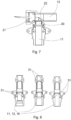
- inlet or outlet lines (11, 12, 18) which are coupled to the inlet or outlet tube (32), whether of the measuring section (13, 14) or of the mixing chamber (17), with coupling and solidly joining means (31) between said inlet or outlet lines (11, 12, 18) and the inlet tube (32) which allow their exchange and modification by threaded parts or of coupling socket of the inlet or outlet line (11, 12, 18) of the type required, as quick connection inlet or outlet lines, different diameters, special connections.
- These coupling and solidly joining means preferably form openings in the section of the inlet or outlet lines (11, 12, 18) wherein a detachable clip is mounted to facilitate its fixing and extraction.
- each liquid inlet or outlet line (11, 12, 18) will have their corresponding sealing gaskets.
Landscapes
- Physics & Mathematics (AREA)
- General Physics & Mathematics (AREA)
- Engineering & Computer Science (AREA)
- Fluid Mechanics (AREA)
- Chemical & Material Sciences (AREA)
- Electromagnetism (AREA)
- Chemical Kinetics & Catalysis (AREA)
- Automation & Control Theory (AREA)
- Thermal Sciences (AREA)
- General Engineering & Computer Science (AREA)
- Mechanical Engineering (AREA)
- Combustion & Propulsion (AREA)
- Remote Sensing (AREA)
- Health & Medical Sciences (AREA)
- Life Sciences & Earth Sciences (AREA)
- Hydrology & Water Resources (AREA)
- Public Health (AREA)
- Water Supply & Treatment (AREA)
- Measuring Volume Flow (AREA)
- Accessories For Mixers (AREA)
Claims (11)
- Betriebsverfahren einer Flüssigkeitsmischvorrichtung mit elektronischer Steuerung der Strömungsregulierung, wobei die Flüssigkeitsmischvorrichtung (10) zwei oder mehr Flüssigkeitszufuhrleitungen (11, 12) aufweist, wobei jede dieser Flüssigkeitszufuhrleitungen (11, 12) einen Messabschnitt (13, 14) aufweist, wobei dieser Messabschnitt (13, 14) einen Temperatur- und Strömungsmesssensor enthält, wobei dieser Temperatur- und Strömungsmesssensor aus zwei Ultraschallumsetzern (21), einem ersten und einem zweiten Ultraschallumsetzer, besteht, wobei die Ultraschallumsetzer (21) mit einem elektronischen Steuersystem (19) verbunden sind, das Informationen über Strömungs- und Temperaturparameter von gemischter Flüssigkeit empfängt, die einem Anwender zugeführt werden soll, und Informationen über von durch die Ultraschallumsetzer (21) ausgeführten Messungen empfängt,
wobei das elektronische Steuersystem (19) auf Strömungsregulierungsmittel (15, 16) wirkt, die in jeder der Flüssigkeitszufuhrleitungen (11, 12) installiert sind, wobei das elektronische Steuersystem (19) für jede Zufuhrleitung wenigstens die folgenden Schritte ausführt:- elektrisches Anregen des ersten Ultraschallumsetzers, der als Emitter betrieben wird,- Messen einer Flugzeit (tdown), die eine Schallwelle braucht, um die Flüssigkeit zu durchqueren, durch Detektieren eines elektrischen Signals, das durch den zweiten Ultraschallumsetzer erzeugt wird, der als Empfänger betrieben wird,- Wiederholen des in den vorhergehenden Schritten beschriebenen Prozesses, aber in einer entgegengesetzten Richtung, d. h. Emittieren einer Schallwelle von dem zweiten Ultraschallumsetzer, der vorher als Empfänger betrieben worden ist und der in diesem Schritt als Emitter wirkt, und Messen einer Flugzeit (tup), die die Schallwelle braucht, um den ersten Ultraschallumsetzer zu erreichen;- Bestimmen einer durchschnittlichen momentanen Fluidgeschwindigkeit, v, unter Verwendung der Messungen der Flugzeiten (tdown, tup) in der und entgegen der Richtung der Strömung der Flüssigkeit, Erkennen der Geometrie des Messabschnitts (13, 14) zwischen dem ersten und zweiten Ultraschallumsetzer (21), des Abstands (L) zwischen dem ersten und zweiten Ultraschallumsetzer (21) und der physikalischen Eigenschaften des Fluids, durch das sich die Schallwelle ausbreitet, wobei es danach möglich ist, eine momentane Strömung zu berechnen, die den Messabschnitt (13, 14) durchquert, wobei die Berechnung der durchschnittlichen momentanen Fluidgeschwindigkeit, die durch den Steuersystemalgorithmus verwendet wird, wie folgt berechnet wird:dadurch gekennzeichnet, dass das Betriebsverfahren die folgenden Schritte umfasst:
tzo die Flugzeit im Ruhezustand, d. h., bei einer Wasserströmungsgeschwindigkeit gleich null ist,- Bestimmen einer momentanen Strömung, die den Messabschnitt (13, 14) durchquert, durch Multiplizieren der durchschnittlichen momentanen Fluidgeschwindigkeit mit einem Rohrquerschnitt der bekannten Geometrie des Messabschnitts (13, 14);- Bestimmen eines Ausbreitungsgeschwindigkeitswerts der Schallwelle durch das grundlegende Betriebsprinzip des Ultraschallmesssystems durch Messen des Unterschieds von Flugzeiten (tdown, tup), die ein Paar von Schallpulsen braucht, um einen bekannten Unterschied in einem Rohr mit bekannter Geometrie zurückzulegen, von dem einer sich in Richtung der Strömung ausbreitet und der andere sich entgegen der Richtung der Strömung ausbreitet,- Bestimmen der Temperatur der Flüssigkeit in dem Messabschnitt (13, 14) basierend auf dem Ausbreitungsgeschwindigkeitswert der Schallwelle und einer Eigenschaft der Geschwindigkeits-Temperatur-Kurve der Flüssigkeit,- wobei dann, wenn dieser bestimmte Flüssigkeitstemperaturwert in einem Bereich der Werte der Geschwindigkeits-Temperatur-Kurve enthalten ist, der Bestimmen der Temperatur durch dieses Verfahren nicht eindeutig ermöglicht, das elektronische Steuersystem (19) die folgenden Schritte ausführt:- Erhalten von Flüssigkeitstemperaturdaten, die durch einen Hilfstemperatursensor (23) basierend auf einer anderen Technik als Ultraschallmessung in der entsprechenden Flüssigkeitszufuhrleitung (11) bereitgestellt werden,- Bestimmen, ob ein richtiger Flüssigkeitstemperaturwert, der durch die Geschwindigkeits-Temperatur-Kurve bestimmt wird, in einem Abschnitt der Geschwindigkeits-Temperatur-Kurve unterhalb eines Maximums oder in einem Abschnitt der Geschwindigkeits-Temperatur-Kurve oberhalb dieses Maximums gefunden wird,- wobei das Steuersystem (19), sobald die Flüssigkeitstemperatur bekannt ist, Anweisungen an die Regulierungsmittel (15, 16) zum Regulieren des Strömungsmischungsanteils jeder der Flüssigkeitszufuhrleitungen (11, 12) sendet. - Betriebsverfahren einer Flüssigkeitsmischvorrichtung mit elektronischer Steuerung der Regulierung nach Anspruch 1, wobei die Informationen über Strömungs- und Temperaturparameter der gemischten Flüssigkeit, die dem Anwender zugeführt werden soll, Strömungs- und Temperaturparameter sind, die durch einen Anwender, durch eine CPU mit vorprogrammierten Werten oder durch ähnliche Systeme der Angabe der Strömungs- und Temperaturparameter der zuzuführenden gemischten Flüssigkeit festgelegt werden.
- Flüssigkeitsmischvorrichtung mit elektronischer Steuerung der Regulierung, umfassend:- zwei oder mehr Flüssigkeitszufuhrleitungen (11, 12),- einen Temperatur- und Strömungsmesssensor der Flüssigkeit für jede der Flüssigkeitszufuhrleitungen (11, 12). wobei dieser Temperatur- und Strömungsmesssensor aus zwei Ultraschallumsetzern (21) besteht,- Regulierungsmittel (15, 16) zum Regulieren des Strömungsmischungsanteils von jeder der Flüssigkeitszufuhrleitungen (11, 12),wobei die Flüssigkeitsmischvorrichtung (10) konfiguriert ist, Informationen über Strömungs- und Temperaturparameter zu empfangen, die durch einen Anwender oder durch eine CPU mit vorprogrammierten Werten oder durch ähnliche Systeme der Angabe der Strömungs- und Temperaturparameter der zuzuführenden gemischten Flüssigkeit festgelegt werden, und- wobei die Flüssigkeitsmischvorrichtung (10) konfiguriert ist, Anweisungen an die Regulierungsmittel (15, 16) zum Regulieren des Strömungsmischungsanteils von jeder der Flüssigkeitszufuhrleitungen (11, 12) zu senden, dadurch gekennzeichnet, dass die Flüssigkeitsmischvorrichtung (10) umfasst:- einen Messabschnitt (13, 14), der sich in jeder der Flüssigkeitszufuhrleitungen (11, 12) befindet;- einen Temperatur- und Strömungsmesssensor, der aus zwei Ultraschallumsetzern (21) besteht, so dass einer als ein Wellenemitter wirkt und der andere als Empfänger davon wirkt und umgekehrt, die konfiguriert sind, Flugzeitmessungen von emittierten Schallwellen in der Flüssigkeit sowohl in der Richtung der Strömung als auch entgegen der Richtung der Strömung auszuführen,- einen Hilfstemperatursensor (23) basierend auf einer anderen Technik als Ultraschallmessung, der in einer der zwei oder mehr Flüssigkeitszufuhrleitungen (11) installiert ist,- ein elektronisches Steuersystem, das konfiguriert ist, das Betriebsverfahren nach einem der Ansprüche 1 und 2 auszuführen,wobei die Ultraschallumsetzer (21) und der Hilfstemperatursensor (23) mit dem elektronischen Steuersystem (19) verbunden sind, das die Messwerte empfängt.
- Flüssigkeitsmischvorrichtung mit elektronischer Steuerung der Regulierung nach Anspruch 3, wobei die Mischvorrichtung (10) eine Konfiguration aufweist, so das die Ultraschallumsetzer (21) außerhalb des Wegs der Flüssigkeitsströmung einander gegenüberliegen und auf die Richtung der Strömung in dem Messabschnitt (13, 14) ausgerichtet sind, einen Abstand (L) zwischen den Ultraschallumsetzern (21) aufweist, der größer als 30 mm und kleiner als 250 mm ist, wobei der Messabschnitt (13, 14) einen Durchmesser zwischen 8 mm und 30 mm aufweist und, in einem Bereich des Zusammentreffens von Einlass- und Auslassabschnitten mit dem Messabschnitt (13, 14), ein Radius (22) in einer inneren Ecke angeordnet worden ist, die ein Kniestück mit einem Durchmesser zwischen 2 mm und 10 mm bildet.
- Flüssigkeitsmischvorrichtung mit elektronischer Steuerung der Regulierung nach Anspruch 4, wobei der Abstand zwischen 60 mm und 120 mm beträgt.
- Flüssigkeitsmischvorrichtung mit elektronischer Steuerung der Regulierung nach Anspruch 4 oder 5, wobei die Mischvorrichtung (10) eine Konfiguration aufweist, derart, dass der Messabschnitt (13, 14) einen Durchmesser zwischen 9 mm und 15 mm aufweist.
- Flüssigkeitsmischvorrichtung mit elektronischer Steuerung der Regulierung nach Anspruch 4, wobei der Abstand 70 mm beträgt, der Messabschnitt (13, 14) einen Durchmesser von 10 mm aufweist und das Kniestück einen Radius von 2,5 mm aufweist.
- Flüssigkeitsmischvorrichtung mit elektronischer Steuerung der Regulierung nach Anspruch 3, wobei die Mischvorrichtung (10) eine Konfiguration aufweist, derart, dass sich der zusätzliche Hilfstemperatursensor (23) hinter dem Messabschnitt (13, 14) befindet.
- Flüssigkeitsmischvorrichtung mit elektronischer Steuerung der Regulierung nach Anspruch 3, wobei die Mischvorrichtung (10) Mittel (30) zum Stabilisieren oder Mittel zum Normieren des Fluidgeschwindigkeitsprofils überall im Eintrittsabschnitt an einer Position nah bei einem Punkt des Zusammentreffens mit dem Messabschnitt (13, 14) aufweist.
- Flüssigkeitsmischvorrichtung mit elektronischer Steuerung der Regulierung nach Anspruch 3, wobei die Strömungsregulierungsmittel (15, 16) Proportional-Solenoidventile sind.
- Flüssigkeitsmischvorrichtung mit elektronischer Steuerung der Regulierung nach einem der vorhergehenden Ansprüche, wobei die Mischvorrichtung (10) unter demselben Gehäuse wie die entsprechenden Flüssigkeitszufuhrleitungen (11, 12) und die vorstehenden Auslassleitungen (18) installiert ist.
Applications Claiming Priority (1)
| Application Number | Priority Date | Filing Date | Title |
|---|---|---|---|
| ES201830599A ES2735648B2 (es) | 2018-06-19 | 2018-06-19 | Dispositivo de mezcla de liquidos con control electronico de alta dinamica de regulacion y metodo de funcionamiento del mismo |
Publications (3)
| Publication Number | Publication Date |
|---|---|
| EP3584665A1 EP3584665A1 (de) | 2019-12-25 |
| EP3584665B1 true EP3584665B1 (de) | 2024-08-07 |
| EP3584665C0 EP3584665C0 (de) | 2024-08-07 |
Family
ID=66826899
Family Applications (1)
| Application Number | Title | Priority Date | Filing Date |
|---|---|---|---|
| EP19179644.0A Active EP3584665B1 (de) | 2018-06-19 | 2019-06-12 | Flüssigkeitsmischvorrichtung mit elektronischer steuerung mit hoher dynamischer regulierung und betriebsverfahren dafür |
Country Status (5)
| Country | Link |
|---|---|
| US (1) | US11040318B2 (de) |
| EP (1) | EP3584665B1 (de) |
| JP (2) | JP2020011230A (de) |
| CN (1) | CN110616776B (de) |
| ES (2) | ES2735648B2 (de) |
Families Citing this family (7)
| Publication number | Priority date | Publication date | Assignee | Title |
|---|---|---|---|---|
| ES2735648B2 (es) * | 2018-06-19 | 2020-05-20 | Sedal S L U | Dispositivo de mezcla de liquidos con control electronico de alta dinamica de regulacion y metodo de funcionamiento del mismo |
| WO2021152036A1 (en) * | 2020-01-31 | 2021-08-05 | AQUA MANAGER ApS | A water supply system |
| CN112082614B (zh) * | 2020-08-27 | 2021-09-10 | 武汉理工大学 | 一种体积流量计辅助启动系统 |
| FR3116115B1 (fr) * | 2020-11-09 | 2022-10-28 | Sagemcom Energy & Telecom Sas | Procédé de mesure de la température de l’eau dans un compteur |
| US12135570B2 (en) | 2021-08-09 | 2024-11-05 | B/E Aerospace, Inc. | Thermostat mixing valve with dual proportional solenoid valves |
| EP4134777B1 (de) * | 2021-08-09 | 2025-11-26 | B/E Aerospace, Inc. | Thermostatmischventil mit doppelt proportionalen magnetventilen |
| CN120122734B (zh) * | 2025-05-12 | 2025-07-04 | 深圳市亮而彩科技有限公司 | 一种基于动态脉宽调制的智能洗护设备控制方法 |
Citations (1)
| Publication number | Priority date | Publication date | Assignee | Title |
|---|---|---|---|---|
| EP0657021B1 (de) * | 1992-08-25 | 1997-04-16 | Kamstrup A/S | Durchflussmesser |
Family Cites Families (48)
| Publication number | Priority date | Publication date | Assignee | Title |
|---|---|---|---|---|
| US4193291A (en) * | 1978-02-27 | 1980-03-18 | Panametrics, Inc. | Slow torsional wave densitometer |
| FR2608717A1 (fr) * | 1986-12-23 | 1988-06-24 | Trubert Ets Rene | Dispositif thermodoseur de fluides |
| JP2556701B2 (ja) * | 1987-05-18 | 1996-11-20 | グラム株式会社 | 限外濾過量及び透析液濃度測定装置 |
| US5369998A (en) * | 1989-12-12 | 1994-12-06 | Commonwealth Scientific And Industrial Research Organisation | Ultrasonic mass flow meter for solids suspended in a gas stream |
| JPH09511570A (ja) * | 1994-04-19 | 1997-11-18 | シーメンス アクチエンゲゼルシヤフト | 超音波変換器の保持装置 |
| JP3216769B2 (ja) * | 1995-03-20 | 2001-10-09 | 富士電機株式会社 | クランプオン型超音波流量計における温度圧力補償方法 |
| US6343511B1 (en) * | 1995-06-07 | 2002-02-05 | Panametrics, Inc. | Ultrasonic path bundle and systems |
| EP0835444A4 (de) * | 1995-06-07 | 1998-11-18 | Panametrics | Ultraschall wegbündel und -system |
| DE19530807C2 (de) * | 1995-08-22 | 1999-11-18 | Krohne Ag Basel | Verfahren zur Bestimmung des Volumendurchflusses von strömenden Medien |
| DE19600455A1 (de) * | 1996-01-09 | 1997-07-17 | Oliver Kudera | Verfahren und Vorrichtung zum Inbetriebsetzen einer Pumpe in einer Zirkulationsleitung |
| US6397683B1 (en) * | 1998-07-22 | 2002-06-04 | Flowtec Ag | Clamp-on ultrasonic flowmeter |
| US6186179B1 (en) * | 1998-09-18 | 2001-02-13 | Panametrics, Inc. | Disturbance simulating flow plate |
| US6513391B2 (en) * | 1999-05-17 | 2003-02-04 | Van Bekkum Jan Aart | Transmitting and/or receiving head for sonic flowmeters |
| JP3552054B2 (ja) * | 2002-01-28 | 2004-08-11 | 松下電器産業株式会社 | 音響整合層および超音波送受波器 |
| US6895985B2 (en) * | 2003-03-17 | 2005-05-24 | Computerized Smart Faucet Ltd. | Smart device and system for improved domestic use and saving of water |
| JPWO2005029912A1 (ja) * | 2003-09-18 | 2006-11-30 | 松下電器産業株式会社 | 超音波振動子を用いた超音波流量計 |
| US7124621B2 (en) * | 2004-07-21 | 2006-10-24 | Horiba Instruments, Inc. | Acoustic flowmeter calibration method |
| GB2428281A (en) * | 2005-07-12 | 2007-01-24 | Alexander Terrell | Electronic mixer valve control |
| KR100973711B1 (ko) * | 2008-04-16 | 2010-08-04 | 정우종 | 디지털 수도 장치 |
| DE102008055116A1 (de) * | 2008-12-23 | 2010-07-01 | Robert Bosch Gmbh | Verfahren zur Herstellung eines Ultraschallwandlers |
| DE102008055123B3 (de) * | 2008-12-23 | 2010-07-22 | Robert Bosch Gmbh | Ultraschallwandler zum Einsatz in einem fluiden Medium |
| US8215183B2 (en) * | 2009-07-03 | 2012-07-10 | Ads Llc | Augmented surface sensor for measuring flow velocity |
| DE102009045020A1 (de) * | 2009-09-25 | 2011-03-31 | Robert Bosch Gmbh | Strömungsmesser für den Einsatz in einem strömenden fluiden Medium |
| DE102009046862A1 (de) * | 2009-11-19 | 2011-05-26 | Endress + Hauser Flowtec Ag | Koppelelement eines Sensors eines Ultraschall-Durchflussmessgeräts |
| JP5682156B2 (ja) * | 2010-06-24 | 2015-03-11 | パナソニックIpマネジメント株式会社 | 超音波式流量計測装置 |
| DE102010040396A1 (de) * | 2010-09-08 | 2012-03-08 | Robert Bosch Gmbh | Durchflussmesser zur Erfassung einer Eigenschaft eines fluiden Mediums |
| DE102011015677A1 (de) * | 2011-03-31 | 2012-10-04 | Rosen Swiss Ag | Akustischer Durchflussmesser |
| US8635913B2 (en) * | 2011-04-21 | 2014-01-28 | General Electric Company | Ultrasonic coupler assembly |
| EP2581715A1 (de) * | 2011-10-13 | 2013-04-17 | Miitors ApS | Ultraschalldurchflussmesser |
| CN103703793B (zh) * | 2012-06-26 | 2015-02-18 | 本多电子株式会社 | 机电转换元件及其制造方法 |
| CN202733114U (zh) * | 2012-08-03 | 2013-02-13 | 北京科勒有限公司 | 电子水龙头 |
| DE102012019217B4 (de) * | 2012-10-01 | 2014-08-07 | Rosen Swiss Ag | Akustischer Durchflussmesser und Verfahren zur Bestimmung des Flusses in einem Objekt |
| US9151651B2 (en) * | 2013-01-14 | 2015-10-06 | General Electric Company | Apparatus and method for determining temperature |
| DE102013003934A1 (de) * | 2013-03-08 | 2014-09-11 | Paw Gmbh & Co. Kg | Vorrichtung zum Erwärmen von Trinkwasser,umfassend einen mit einem Wärmemedium beschickten Wärmetauscher |
| US9494453B2 (en) * | 2013-03-25 | 2016-11-15 | Woojin Inc. | Ultrasonic sensor for high temperature and manufacturing method thereof |
| WO2014174678A1 (ja) * | 2013-04-26 | 2014-10-30 | 三菱電機株式会社 | ヒートポンプ給湯機及びヒートポンプ給湯機を備えた貯湯システム |
| WO2015133834A1 (ko) * | 2014-03-05 | 2015-09-11 | 이장우 | 유량조절편의 틸팅 각도 제한 기능을 가지는 유량 조절 유닛 |
| WO2016138380A1 (en) * | 2015-02-27 | 2016-09-01 | Maquet Cardiopulmonary Ag | Fluid flow rate measuring and gas bubble detecting apparatus |
| DE102015107752A1 (de) * | 2015-05-18 | 2016-11-24 | Endress + Hauser Flowtec Ag | Verfahren zur Ermittlung zumindest einer Rohrwandresonanzfrequenz sowie Clamp-On-Ultraschall-Durchflussmessgerät |
| CN204901002U (zh) * | 2015-07-30 | 2015-12-23 | 芜湖美的厨卫电器制造有限公司 | 混水器系统和混水器 |
| WO2017099852A1 (en) * | 2015-08-12 | 2017-06-15 | Los Alamos National Security, Llc | Detection and monitoring of changes in metallic structures using multimode acoustic signals |
| US10809235B2 (en) * | 2015-10-21 | 2020-10-20 | Texas Instruments Incorporated | Ultrasonic transducer system and method for bi-modal system responses |
| GB2545164B (en) * | 2015-11-24 | 2019-09-25 | Schlumberger Holdings | A stratified flow multiphase flowmeter |
| US20190100083A1 (en) * | 2017-10-03 | 2019-04-04 | Ford Global Technologies, Llc | Controlling sun load in an autonomous vehicle to conserve energy |
| EP3489634B1 (de) * | 2017-11-22 | 2020-08-05 | Levitronix GmbH | Ultraschall-messvorrichtung und verfahren zur ultraschallmessung an einem strömenden fluid |
| CN107905305A (zh) * | 2017-11-24 | 2018-04-13 | 中国计量大学 | 一种智能环保的淋浴控制系统 |
| US10732071B2 (en) * | 2018-04-19 | 2020-08-04 | Dean Ruiz Fung-A Wing | Wireless water control system |
| ES2735648B2 (es) * | 2018-06-19 | 2020-05-20 | Sedal S L U | Dispositivo de mezcla de liquidos con control electronico de alta dinamica de regulacion y metodo de funcionamiento del mismo |
-
2018
- 2018-06-19 ES ES201830599A patent/ES2735648B2/es active Active
-
2019
- 2019-06-12 EP EP19179644.0A patent/EP3584665B1/de active Active
- 2019-06-12 ES ES19179644T patent/ES2987109T3/es active Active
- 2019-06-18 JP JP2019112877A patent/JP2020011230A/ja active Pending
- 2019-06-19 CN CN201910532622.1A patent/CN110616776B/zh active Active
- 2019-06-19 US US16/445,412 patent/US11040318B2/en active Active
-
2023
- 2023-05-15 JP JP2023001644U patent/JP3243563U/ja active Active
Patent Citations (1)
| Publication number | Priority date | Publication date | Assignee | Title |
|---|---|---|---|---|
| EP0657021B1 (de) * | 1992-08-25 | 1997-04-16 | Kamstrup A/S | Durchflussmesser |
Non-Patent Citations (1)
| Title |
|---|
| CHUL-HO LEE ET AL: "An implementation of ultrasonic water meter using dToF measurement", COGENT ENGINEERING, vol. 4, no. 1, 29 August 2017 (2017-08-29), XP055477650, DOI: 10.1080/23311916.2017.1371577 * |
Also Published As
| Publication number | Publication date |
|---|---|
| EP3584665C0 (de) | 2024-08-07 |
| CN110616776B (zh) | 2022-10-21 |
| JP2020011230A (ja) | 2020-01-23 |
| EP3584665A1 (de) | 2019-12-25 |
| US11040318B2 (en) | 2021-06-22 |
| US20190381464A1 (en) | 2019-12-19 |
| JP3243563U (ja) | 2023-09-04 |
| ES2735648B2 (es) | 2020-05-20 |
| ES2735648A1 (es) | 2019-12-19 |
| CN110616776A (zh) | 2019-12-27 |
| ES2987109T3 (es) | 2024-11-13 |
Similar Documents
| Publication | Publication Date | Title |
|---|---|---|
| US11040318B2 (en) | Liquid mixing device with electronic control of high dynamic regulation and operating method thereof | |
| CN102077061B (zh) | 速度增强的流量测量 | |
| KR20100128346A (ko) | 실시간 비정상류 유량계 | |
| US6220090B1 (en) | Air flow meter | |
| WO2012065276A1 (en) | Determining the heat flow emanating from a heat transporting fluid | |
| CA2589198C (en) | System and method for flow profile calibration correction for ultrasonic flowmeters | |
| JP2022028913A (ja) | 流動蒸気圧装置および関連方法 | |
| AU2019462931B2 (en) | True vapor pressure and flashing detection apparatus and related method | |
| RU2624593C1 (ru) | Установка для поверки счетчиков горячей воды | |
| EP3798582B1 (de) | Ultraschalldurchflussmesser und flüssigkeitsleitung | |
| Pirow | Development of a non-invasive water flow meter for a smart geyser | |
| EP4392748B1 (de) | Ultraschall-durchflussmesser mit inneren und äusseren strömungskanälen | |
| JP2004191103A (ja) | 整圧器および流量計測方法 | |
| CN101419085A (zh) | 污水流量恒流检测系统 | |
| Alaeddin et al. | CFD Study of Calibration Factor for Cross Correlation Based Ultrasonic Flowmeter at Different Upstream Pipe Lengths | |
| JP6537566B2 (ja) | 感温素子の駆動方法、駆動装置、および渦流量計 | |
| JP2002181594A (ja) | 流量制御ユニット | |
| JPS61289411A (ja) | 減圧弁制御装置 |
Legal Events
| Date | Code | Title | Description |
|---|---|---|---|
| PUAI | Public reference made under article 153(3) epc to a published international application that has entered the european phase |
Free format text: ORIGINAL CODE: 0009012 |
|
| STAA | Information on the status of an ep patent application or granted ep patent |
Free format text: STATUS: THE APPLICATION HAS BEEN PUBLISHED |
|
| AK | Designated contracting states |
Kind code of ref document: A1 Designated state(s): AL AT BE BG CH CY CZ DE DK EE ES FI FR GB GR HR HU IE IS IT LI LT LU LV MC MK MT NL NO PL PT RO RS SE SI SK SM TR |
|
| AX | Request for extension of the european patent |
Extension state: BA ME |
|
| STAA | Information on the status of an ep patent application or granted ep patent |
Free format text: STATUS: REQUEST FOR EXAMINATION WAS MADE |
|
| 17P | Request for examination filed |
Effective date: 20200625 |
|
| RBV | Designated contracting states (corrected) |
Designated state(s): AL AT BE BG CH CY CZ DE DK EE ES FI FR GB GR HR HU IE IS IT LI LT LU LV MC MK MT NL NO PL PT RO RS SE SI SK SM TR |
|
| STAA | Information on the status of an ep patent application or granted ep patent |
Free format text: STATUS: EXAMINATION IS IN PROGRESS |
|
| 17Q | First examination report despatched |
Effective date: 20200814 |
|
| GRAP | Despatch of communication of intention to grant a patent |
Free format text: ORIGINAL CODE: EPIDOSNIGR1 |
|
| STAA | Information on the status of an ep patent application or granted ep patent |
Free format text: STATUS: GRANT OF PATENT IS INTENDED |
|
| INTG | Intention to grant announced |
Effective date: 20240311 |
|
| GRAS | Grant fee paid |
Free format text: ORIGINAL CODE: EPIDOSNIGR3 |
|
| GRAA | (expected) grant |
Free format text: ORIGINAL CODE: 0009210 |
|
| STAA | Information on the status of an ep patent application or granted ep patent |
Free format text: STATUS: THE PATENT HAS BEEN GRANTED |
|
| AK | Designated contracting states |
Kind code of ref document: B1 Designated state(s): AL AT BE BG CH CY CZ DE DK EE ES FI FR GB GR HR HU IE IS IT LI LT LU LV MC MK MT NL NO PL PT RO RS SE SI SK SM TR |
|
| REG | Reference to a national code |
Ref country code: GB Ref legal event code: FG4D |
|
| REG | Reference to a national code |
Ref country code: CH Ref legal event code: EP |
|
| REG | Reference to a national code |
Ref country code: DE Ref legal event code: R096 Ref document number: 602019056450 Country of ref document: DE |
|
| REG | Reference to a national code |
Ref country code: IE Ref legal event code: FG4D |
|
| U01 | Request for unitary effect filed |
Effective date: 20240906 |
|
| U07 | Unitary effect registered |
Designated state(s): AT BE BG DE DK EE FI FR IT LT LU LV MT NL PT RO SE SI Effective date: 20240923 |
|
| REG | Reference to a national code |
Ref country code: ES Ref legal event code: FG2A Ref document number: 2987109 Country of ref document: ES Kind code of ref document: T3 Effective date: 20241113 |
|
| PG25 | Lapsed in a contracting state [announced via postgrant information from national office to epo] |
Ref country code: NO Free format text: LAPSE BECAUSE OF FAILURE TO SUBMIT A TRANSLATION OF THE DESCRIPTION OR TO PAY THE FEE WITHIN THE PRESCRIBED TIME-LIMIT Effective date: 20241107 |
|
| PG25 | Lapsed in a contracting state [announced via postgrant information from national office to epo] |
Ref country code: PL Free format text: LAPSE BECAUSE OF FAILURE TO SUBMIT A TRANSLATION OF THE DESCRIPTION OR TO PAY THE FEE WITHIN THE PRESCRIBED TIME-LIMIT Effective date: 20240807 Ref country code: GR Free format text: LAPSE BECAUSE OF FAILURE TO SUBMIT A TRANSLATION OF THE DESCRIPTION OR TO PAY THE FEE WITHIN THE PRESCRIBED TIME-LIMIT Effective date: 20241108 |
|
| PG25 | Lapsed in a contracting state [announced via postgrant information from national office to epo] |
Ref country code: IS Free format text: LAPSE BECAUSE OF FAILURE TO SUBMIT A TRANSLATION OF THE DESCRIPTION OR TO PAY THE FEE WITHIN THE PRESCRIBED TIME-LIMIT Effective date: 20241207 |
|
| PG25 | Lapsed in a contracting state [announced via postgrant information from national office to epo] |
Ref country code: HR Free format text: LAPSE BECAUSE OF FAILURE TO SUBMIT A TRANSLATION OF THE DESCRIPTION OR TO PAY THE FEE WITHIN THE PRESCRIBED TIME-LIMIT Effective date: 20240807 |
|
| PG25 | Lapsed in a contracting state [announced via postgrant information from national office to epo] |
Ref country code: RS Free format text: LAPSE BECAUSE OF FAILURE TO SUBMIT A TRANSLATION OF THE DESCRIPTION OR TO PAY THE FEE WITHIN THE PRESCRIBED TIME-LIMIT Effective date: 20241107 |
|
| PG25 | Lapsed in a contracting state [announced via postgrant information from national office to epo] |
Ref country code: RS Free format text: LAPSE BECAUSE OF FAILURE TO SUBMIT A TRANSLATION OF THE DESCRIPTION OR TO PAY THE FEE WITHIN THE PRESCRIBED TIME-LIMIT Effective date: 20241107 Ref country code: PL Free format text: LAPSE BECAUSE OF FAILURE TO SUBMIT A TRANSLATION OF THE DESCRIPTION OR TO PAY THE FEE WITHIN THE PRESCRIBED TIME-LIMIT Effective date: 20240807 Ref country code: NO Free format text: LAPSE BECAUSE OF FAILURE TO SUBMIT A TRANSLATION OF THE DESCRIPTION OR TO PAY THE FEE WITHIN THE PRESCRIBED TIME-LIMIT Effective date: 20241107 Ref country code: IS Free format text: LAPSE BECAUSE OF FAILURE TO SUBMIT A TRANSLATION OF THE DESCRIPTION OR TO PAY THE FEE WITHIN THE PRESCRIBED TIME-LIMIT Effective date: 20241207 Ref country code: HR Free format text: LAPSE BECAUSE OF FAILURE TO SUBMIT A TRANSLATION OF THE DESCRIPTION OR TO PAY THE FEE WITHIN THE PRESCRIBED TIME-LIMIT Effective date: 20240807 Ref country code: GR Free format text: LAPSE BECAUSE OF FAILURE TO SUBMIT A TRANSLATION OF THE DESCRIPTION OR TO PAY THE FEE WITHIN THE PRESCRIBED TIME-LIMIT Effective date: 20241108 |
|
| PG25 | Lapsed in a contracting state [announced via postgrant information from national office to epo] |
Ref country code: SM Free format text: LAPSE BECAUSE OF FAILURE TO SUBMIT A TRANSLATION OF THE DESCRIPTION OR TO PAY THE FEE WITHIN THE PRESCRIBED TIME-LIMIT Effective date: 20240807 |
|
| PG25 | Lapsed in a contracting state [announced via postgrant information from national office to epo] |
Ref country code: CZ Free format text: LAPSE BECAUSE OF FAILURE TO SUBMIT A TRANSLATION OF THE DESCRIPTION OR TO PAY THE FEE WITHIN THE PRESCRIBED TIME-LIMIT Effective date: 20240807 |
|
| PG25 | Lapsed in a contracting state [announced via postgrant information from national office to epo] |
Ref country code: SK Free format text: LAPSE BECAUSE OF FAILURE TO SUBMIT A TRANSLATION OF THE DESCRIPTION OR TO PAY THE FEE WITHIN THE PRESCRIBED TIME-LIMIT Effective date: 20240807 |
|
| U20 | Renewal fee for the european patent with unitary effect paid |
Year of fee payment: 7 Effective date: 20250506 |
|
| PLBE | No opposition filed within time limit |
Free format text: ORIGINAL CODE: 0009261 |
|
| STAA | Information on the status of an ep patent application or granted ep patent |
Free format text: STATUS: NO OPPOSITION FILED WITHIN TIME LIMIT |
|
| PGFP | Annual fee paid to national office [announced via postgrant information from national office to epo] |
Ref country code: GB Payment date: 20250515 Year of fee payment: 7 |
|
| 26N | No opposition filed |
Effective date: 20250508 |
|
| PGFP | Annual fee paid to national office [announced via postgrant information from national office to epo] |
Ref country code: ES Payment date: 20250701 Year of fee payment: 7 |
|
| REG | Reference to a national code |
Ref country code: CH Ref legal event code: H13 Free format text: ST27 STATUS EVENT CODE: U-0-0-H10-H13 (AS PROVIDED BY THE NATIONAL OFFICE) Effective date: 20260127 |
|
| PG25 | Lapsed in a contracting state [announced via postgrant information from national office to epo] |
Ref country code: MC Free format text: LAPSE BECAUSE OF FAILURE TO SUBMIT A TRANSLATION OF THE DESCRIPTION OR TO PAY THE FEE WITHIN THE PRESCRIBED TIME-LIMIT Effective date: 20240807 |
|
| PG25 | Lapsed in a contracting state [announced via postgrant information from national office to epo] |
Ref country code: IE Free format text: LAPSE BECAUSE OF NON-PAYMENT OF DUE FEES Effective date: 20250612 |
|
| PG25 | Lapsed in a contracting state [announced via postgrant information from national office to epo] |
Ref country code: CH Free format text: LAPSE BECAUSE OF NON-PAYMENT OF DUE FEES Effective date: 20250630 |
|
| U20 | Renewal fee for the european patent with unitary effect paid |
Year of fee payment: 8 Effective date: 20260408 |