EP3584469B1 - Fahrzeugschalthebelvorrichtung und verfahren zur bereitstellung davon - Google Patents
Fahrzeugschalthebelvorrichtung und verfahren zur bereitstellung davon Download PDFInfo
- Publication number
- EP3584469B1 EP3584469B1 EP19180929.2A EP19180929A EP3584469B1 EP 3584469 B1 EP3584469 B1 EP 3584469B1 EP 19180929 A EP19180929 A EP 19180929A EP 3584469 B1 EP3584469 B1 EP 3584469B1
- Authority
- EP
- European Patent Office
- Prior art keywords
- lever
- driver
- lock
- range
- lock lever
- Prior art date
- Legal status (The legal status is an assumption and is not a legal conclusion. Google has not performed a legal analysis and makes no representation as to the accuracy of the status listed.)
- Active
Links
Images





Classifications
-
- F—MECHANICAL ENGINEERING; LIGHTING; HEATING; WEAPONS; BLASTING
- F16—ENGINEERING ELEMENTS AND UNITS; GENERAL MEASURES FOR PRODUCING AND MAINTAINING EFFECTIVE FUNCTIONING OF MACHINES OR INSTALLATIONS; THERMAL INSULATION IN GENERAL
- F16H—GEARING
- F16H59/00—Control inputs to control units of change-speed- or reversing-gearings for conveying rotary motion
- F16H59/02—Selector apparatus
- F16H59/08—Range selector apparatus
- F16H59/10—Range selector apparatus comprising levers
-
- F—MECHANICAL ENGINEERING; LIGHTING; HEATING; WEAPONS; BLASTING
- F16—ENGINEERING ELEMENTS AND UNITS; GENERAL MEASURES FOR PRODUCING AND MAINTAINING EFFECTIVE FUNCTIONING OF MACHINES OR INSTALLATIONS; THERMAL INSULATION IN GENERAL
- F16H—GEARING
- F16H59/00—Control inputs to control units of change-speed- or reversing-gearings for conveying rotary motion
- F16H59/02—Selector apparatus
- F16H59/0278—Constructional features of the selector lever, e.g. grip parts, mounting or manufacturing
-
- B—PERFORMING OPERATIONS; TRANSPORTING
- B60—VEHICLES IN GENERAL
- B60K—ARRANGEMENT OR MOUNTING OF PROPULSION UNITS OR OF TRANSMISSIONS IN VEHICLES; ARRANGEMENT OR MOUNTING OF PLURAL DIVERSE PRIME-MOVERS IN VEHICLES; AUXILIARY DRIVES FOR VEHICLES; INSTRUMENTATION OR DASHBOARDS FOR VEHICLES; ARRANGEMENTS IN CONNECTION WITH COOLING, AIR INTAKE, GAS EXHAUST OR FUEL SUPPLY OF PROPULSION UNITS IN VEHICLES
- B60K20/00—Arrangement or mounting of change-speed gearing control devices in vehicles
- B60K20/02—Arrangement or mounting of change-speed gearing control devices in vehicles of initiating means
-
- F—MECHANICAL ENGINEERING; LIGHTING; HEATING; WEAPONS; BLASTING
- F16—ENGINEERING ELEMENTS AND UNITS; GENERAL MEASURES FOR PRODUCING AND MAINTAINING EFFECTIVE FUNCTIONING OF MACHINES OR INSTALLATIONS; THERMAL INSULATION IN GENERAL
- F16H—GEARING
- F16H59/00—Control inputs to control units of change-speed- or reversing-gearings for conveying rotary motion
- F16H59/02—Selector apparatus
- F16H59/08—Range selector apparatus
- F16H59/10—Range selector apparatus comprising levers
- F16H59/105—Range selector apparatus comprising levers consisting of electrical switches or sensors
-
- F—MECHANICAL ENGINEERING; LIGHTING; HEATING; WEAPONS; BLASTING
- F16—ENGINEERING ELEMENTS AND UNITS; GENERAL MEASURES FOR PRODUCING AND MAINTAINING EFFECTIVE FUNCTIONING OF MACHINES OR INSTALLATIONS; THERMAL INSULATION IN GENERAL
- F16H—GEARING
- F16H59/00—Control inputs to control units of change-speed- or reversing-gearings for conveying rotary motion
- F16H59/02—Selector apparatus
- F16H59/08—Range selector apparatus
- F16H59/12—Range selector apparatus comprising push button devices
-
- F—MECHANICAL ENGINEERING; LIGHTING; HEATING; WEAPONS; BLASTING
- F16—ENGINEERING ELEMENTS AND UNITS; GENERAL MEASURES FOR PRODUCING AND MAINTAINING EFFECTIVE FUNCTIONING OF MACHINES OR INSTALLATIONS; THERMAL INSULATION IN GENERAL
- F16H—GEARING
- F16H61/00—Control functions within control units of change-speed- or reversing-gearings for conveying rotary motion ; Control of exclusively fluid gearing, friction gearing, gearings with endless flexible members or other particular types of gearing
- F16H61/18—Preventing unintentional or unsafe shift, e.g. preventing manual shift from highest gear to reverse gear
-
- F—MECHANICAL ENGINEERING; LIGHTING; HEATING; WEAPONS; BLASTING
- F16—ENGINEERING ELEMENTS AND UNITS; GENERAL MEASURES FOR PRODUCING AND MAINTAINING EFFECTIVE FUNCTIONING OF MACHINES OR INSTALLATIONS; THERMAL INSULATION IN GENERAL
- F16H—GEARING
- F16H61/00—Control functions within control units of change-speed- or reversing-gearings for conveying rotary motion ; Control of exclusively fluid gearing, friction gearing, gearings with endless flexible members or other particular types of gearing
- F16H61/22—Locking of the control input devices
-
- F—MECHANICAL ENGINEERING; LIGHTING; HEATING; WEAPONS; BLASTING
- F16—ENGINEERING ELEMENTS AND UNITS; GENERAL MEASURES FOR PRODUCING AND MAINTAINING EFFECTIVE FUNCTIONING OF MACHINES OR INSTALLATIONS; THERMAL INSULATION IN GENERAL
- F16H—GEARING
- F16H59/00—Control inputs to control units of change-speed- or reversing-gearings for conveying rotary motion
- F16H59/02—Selector apparatus
- F16H2059/026—Details or special features of the selector casing or lever support
-
- F—MECHANICAL ENGINEERING; LIGHTING; HEATING; WEAPONS; BLASTING
- F16—ENGINEERING ELEMENTS AND UNITS; GENERAL MEASURES FOR PRODUCING AND MAINTAINING EFFECTIVE FUNCTIONING OF MACHINES OR INSTALLATIONS; THERMAL INSULATION IN GENERAL
- F16H—GEARING
- F16H59/00—Control inputs to control units of change-speed- or reversing-gearings for conveying rotary motion
- F16H59/02—Selector apparatus
- F16H59/0278—Constructional features of the selector lever, e.g. grip parts, mounting or manufacturing
- F16H2059/0282—Lever handles with lock mechanisms, e.g. for allowing selection of reverse gear or releasing lever from park position
-
- F—MECHANICAL ENGINEERING; LIGHTING; HEATING; WEAPONS; BLASTING
- F16—ENGINEERING ELEMENTS AND UNITS; GENERAL MEASURES FOR PRODUCING AND MAINTAINING EFFECTIVE FUNCTIONING OF MACHINES OR INSTALLATIONS; THERMAL INSULATION IN GENERAL
- F16H—GEARING
- F16H61/00—Control functions within control units of change-speed- or reversing-gearings for conveying rotary motion ; Control of exclusively fluid gearing, friction gearing, gearings with endless flexible members or other particular types of gearing
- F16H61/18—Preventing unintentional or unsafe shift, e.g. preventing manual shift from highest gear to reverse gear
- F16H2061/185—Means, e.g. catches or interlocks, for preventing unintended shift into reverse gear
-
- F—MECHANICAL ENGINEERING; LIGHTING; HEATING; WEAPONS; BLASTING
- F16—ENGINEERING ELEMENTS AND UNITS; GENERAL MEASURES FOR PRODUCING AND MAINTAINING EFFECTIVE FUNCTIONING OF MACHINES OR INSTALLATIONS; THERMAL INSULATION IN GENERAL
- F16H—GEARING
- F16H61/00—Control functions within control units of change-speed- or reversing-gearings for conveying rotary motion ; Control of exclusively fluid gearing, friction gearing, gearings with endless flexible members or other particular types of gearing
- F16H61/22—Locking of the control input devices
- F16H2061/223—Electrical gear shift lock, e.g. locking of lever in park or neutral position by electric means if brake is not applied; Key interlock, i.e. locking the key if lever is not in park position
-
- F—MECHANICAL ENGINEERING; LIGHTING; HEATING; WEAPONS; BLASTING
- F16—ENGINEERING ELEMENTS AND UNITS; GENERAL MEASURES FOR PRODUCING AND MAINTAINING EFFECTIVE FUNCTIONING OF MACHINES OR INSTALLATIONS; THERMAL INSULATION IN GENERAL
- F16H—GEARING
- F16H61/00—Control functions within control units of change-speed- or reversing-gearings for conveying rotary motion ; Control of exclusively fluid gearing, friction gearing, gearings with endless flexible members or other particular types of gearing
- F16H61/24—Providing feel, e.g. to enable selection
- F16H2061/243—Cams or detent arrays for guiding and providing feel
Definitions
- the present invention relates to a vehicle shifter device and to a method of providing the same.
- the vehicle shifter device suppresses a misoperation by the driver and ensures a high level of security.
- the driver since the depression depth of the push button in the second operation is larger than that of the first operation, the driver needs to intentionally press the push button more deeply during a switchover between the P-range and the R-range, thereby suppressing a misoperation more reliably.
- the lock lever moves up and down in response to depression of the push button by the driver and, when the lock lever moves up and down, the lock lever is locked to or released from the lever location holding part. Accordingly, the location of the shift lever can be surely held in individual positions using a simple structure.
- the lever location holding part is a lock plate having a plurality of concave parts recessed upward so as to correspond to the plurality of positions of the shift lever
- the lock plate includes a first extension portion along the path of the movement of the shift lever when the driver performs a switchover between the parking range and the reverse range and a second extension portion along the path of the movement of the shift lever when the driver performs a switchover among the reverse range, the neutral range, and the drive range
- the first extension portion being formed integrally with the second extension portion, and has an L shape as a whole in plan view seen from above, and/or the concave parts to which the first lock lever is locked when the parking range and the reverse range are selected may be formed in the first extension portion, and the concave parts to which the second lock lever is locked when the reverse range, the neutral range, and the drive range are selected may be formed in the second extension portion.
- the first lock lever and the second lock lever project from the lever body and the direction in which the first lock lever projects from the lever body is opposite to that of the second lock lever.
- the lock plate is L-shaped (or may be inverted-L-shaped depending on the viewing direction) in plan view.
- the plurality of concave parts provided in the first extension portion of the lock plate may include a first concave part that locks the first lock lever when the driver selects the parking range and a second concave part that locks the first lock lever when the driver selects the reverse range
- the plurality of concave parts provided in the second extension portion of the lock plate may include a third concave part that locks the second lock lever when the driver selects the reverse range and a fourth concave part that locks the second lock lever when the driver selects the neutral range
- a first convex part projecting downward may be provided between the first concave part and the second concave part in the first extension portion of the lock plate
- a second convex part projecting downward may be provided between the third concave part and the fourth concave part in the second extension portion of the lock plate
- a height of the first convex part relative to bottoms of the first concave part and the second concave part may be larger than a height of the second convex
- An acceleration pedal 9 and a brake pedal 10 are disposed in a foot part in front of the driver.
- the center console 7 is provided with a vehicle shifter device 3 and a parking switch 8.
- the driver causes an automatic transmission (not illustrated) of the vehicle 1 to perform a switchover among a plurality of speed ranges by operating the vehicle shifter device 3.
- the vehicle shifter device 3 can perform a switchover among speed ranges including a parking range (P-range), a reverse range (R-range), a neutral range (N-range), and a drive range (D-range).
- P-range parking range
- R-range reverse range
- N-range neutral range
- D-range drive range
- the shift lever 11 passing through the opening 14 in a Z-direction is provided in the opening 14 of the center console 7.
- a shift knob 12 grasped by the driver is provided in the upper end part (end part in the front of the sheet in Fig. 2 ) of the shift lever 11.
- the shift knob 12 is provided with a push button 13 projecting toward a +X side (driver seat side). The push button 13 is depressed when the driver performs a switchover among speed ranges.
- Indicators 16 (16p, 16r, 16n, and 16d) that indicate shift positions are provided on the +X side and a -X side of the opening 14.
- One of these indicators 16p, 16r, 16n, and 16d that corresponds to the selected shift position emits from a -Z side (the back of the sheet in Fig. 2 ) so that the driver can visually recognize the shift position easily.
- a parking (P) position 3p and a reverse (R) position 3r are disposed along an X-direction.
- the P-position 3p and the R-position 3r are disposed on a straight line Ax1 extending in the X-direction.
- the R-position 3r, a neutral (N) position 3n, and a drive (D) position 3d are disposed along a Y-direction. That is, the R-position 3r, the N-position 3n, and the D-position 3d are disposed on a straight line Ax2 extending in the Y-direction.
- the motion of the shift lever 11 between the P-position 3p and the R-position 3r is detected by an electric signal (by a shift-by-wire method) and the motion of the shift lever 11 among the R-position 3r, the N-position 3n, and the D-position 3d is sent to the automatic transmission as a speed change instruction via a coupled cable.
- Fig. 3 is a schematic side view illustrating the structure of the shift lever 11 in which the shift knob 12 is represented by a dashed line to clarify the internal structure.
- the shift lever 11 includes a cylindrical upper lever body 17, a lower lever body 18 formed integrally with the upper lever body 17 on the -Z side of the upper lever body 17, and a rod 19 movable within the cylinders of the upper lever body 17 and the lower lever body 18 in the Z-direction.
- the rod 19 has a first lock lever 21 projecting toward the +X side from a middle part in the Z-direction and a second lock lever 22 projecting toward the -X side from the middle part in the Z-direction.
- the first lock lever 21 and the second lock lever 22 are movable up and down in the Z-direction integrally with the rod 19.
- the detent plunger 24 can move in or out of the detent case 23 and provides tactile feeling concerning operation for the driver when the shift lever 11 enters the individual shift position.
- Fig. 4 illustrates the locations of the lock levers of the shift lever
- Fig. 4(a) is a schematic cross sectional view illustrating the state in which the driver does not depress the push button
- Fig. 4(b) is a schematic cross sectional view illustrating the state in which the driver has shallowly depressed the push button
- Fig. 4(c) is a schematic cross sectional view illustrating the state in which the driver has deeply depressed the push button.
- the first lock lever 21 and the second lock lever 22 are located in the upper ends of the movable ranges in the Z-direction. Accordingly, the upper ends of the first lock lever 21 and the second lock lever 22 are located at a height H 1 from the center P 20 (see Fig. 3 ).
- first lock lever 21 projects outside through an opening 17a opened in the upper lever body 17 and the second lock lever 22 projects outside through an opening 17b.
- first lock lever 21 and the second lock lever 22 move integrally with the rod 19 that moves within a cylinder space 17c of the upper lever body 17 and a cylinder space 18a of the lower lever body 18 in the Z-direction.
- Fig. 5 is a schematic cross sectional view taken along line V-V in Fig. 3 .
- the first lock lever 21 projects from the rod 19 toward the +X side and the second lock lever 22 projects from the rod 19 toward the -X side.
- the first lock lever 21 has one end connected to the rod 19 and includes a root portion 21a that extends toward the +X side and a front end portion 21b that is bent toward a +Y side at the end part on the +X side of the root portion 21a, extends toward the +Y side, and is formed integrally with the root portion 21a.
- the vehicle shifter device 3 has a lock plate 28 provided in the interior (back surface side) of the center console 7.
- the lock plate 28 is provided as a lever location holding part that locks the lock levers 21 and 22 of the shift lever 11 in the individual shift positions and holds the location of the shift lever 11.
- the structure of the lock plate 28 will be described with reference to Fig. 6 to Fig. 8 .
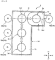
- Fig. 6 is a schematic plan view illustrating the structure of the lock plate 28 provided on the back surface side of the center console 7, seen from the lower side (-Z side) of the vehicle 1
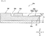
- Fig. 7 is schematic cross sectional view taken along line VII-VII in Fig. 6
- Fig. 8 is a schematic cross sectional view taken along line VIII-VIII in Fig. 8 .
- the first extension portion 28j of the lock plate 28 is provided with concave parts 28c and 28d recessed toward the +Z side and convex parts 28f, 28g, and 28h projecting toward the -Z side.
- the convex part 28g has a projection height higher toward the -Z side than the convex part 28f.
- the convex part 28h is provided between the concave part 28c and the concave part 28d in the X-direction.
- the concave part 28d has a deep bottom portion 28d 1 deeply recessed toward the -Z side and a shallow bottom portion 28d 2 having a recess depth shallower than the deep bottom portion 28d 1 and disposed on the +X side of the deep bottom portion 28d 1 .
- the concave part 28a includes an oblique surface portion 28a 1 provided on a -Y side and configured by an oblique surface having a difference in height in the Z-direction and a second portion 28a 2 provided on the +Y side of the oblique surface portion 28a 1 and configured by a bottom that is a flat surface along the Y-direction.
- the lock plate 28 is disposed on the back surface side of the center console 7 and connected to a mount plate 29 connected to the vehicle body of the vehicle 1.
- the height of the convex part 28h with respect to a surface 29a on the -Z side of the mount plate 29 is assumed to be H 4 and the height with respect to the surface 29a of the convex part 28g is assumed to be H 5 .
- the height from the bottom of the concave part 28c and the deep bottom portion 28d 1 of the concave part 28d to the top of the convex part 28h is assumed to be H 6 .
- the height of the convex part 28e with respect to the surface 29a on the -Z side of the mount plate 29 is assumed to be H 7
- the height from the bottom of the concave part 28b and the planar portion 28a 2 of the concave part 28a to the top of the convex parts 28e and 28f is assumed to be H 8 .
- the vehicle shifter device 3 according to the embodiment meets the following relationship. H 4 > H 7 H 6 > H 8 H 4 ⁇ H 5
- the first extension portion 28j of the lock plate 28 is provided with a hole 28i penetrating through the first extension portion 28j in the thickness direction (Y-direction) thereof.
- a plunger 30a of a solenoid 30 is inserted into the hole 28i.
- the plunger 30a can move in and out in the Y-direction as indicated by arrow C.
- the area to which the plunger 30a projects is the area on the -Y side of the lock plate 28 in which the lever bodies 17 and 18 of the shift lever 11 are movable.
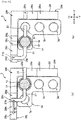
- Fig. 9(a) is a schematic plan view illustrating the state of the lock levers 21 and 22 with respect to the lock plate 28 when the shift position is the D-position
- Fig. 9(b) is a schematic plan view illustrating the state of the lock levers 21 and 22 with respect to the lock plate 28 when the shift position is the N-position
- Fig. 10(a) is a schematic plan view illustrating the state of the lock levers 21 and 22 with respect to the lock plate 28 when the shift position is the R-position
- Fig. 10(b) is a schematic plan view illustrating the state of the lock levers 21 and 22 with respect to the lock plate 28 when the shift position is the P-position.
- the second lock lever 22 is located in the end area on the +Y side of the concave part 28a of the second extension portion 28k of the lock plate 28.
- Fig. 11 is a schematic plan view illustrating the state of the plunger 30a with respect to the shift lever 11 when the shift position is the P-position.
- the plunger 30a of the solenoid 30 projects toward the -Y side of the first extension portion 28j of the lock plate 28. Accordingly, if the driver tries to move the shift lever 11 toward the -X side by depressing only the push button 13, the plunger 30a makes contact with the lever body 17 or the lever body 18 (the lever body 18 is not illustrated in Fig. 11 ) and prevents the shift lever 11 from moving to the -X side.
- the operation that depresses the push button 13 shallowly is adopted as an example of the first operation as illustrated in Fig. 4(b) and the operation that depresses the push button 13 deeply is adopted as an example of the second operation as illustrated in Fig. 4(c) in the above embodiment
- the invention is not limited to this example.
- first lock lever 21 is L-shaped in plan view in the above embodiment, the invention is not limited to this example.
- the first lock lever may have a shape extending linearly like the second lock lever.
- lock levers (the first lock lever 21 and the second lock lever 22) are connected to the rod 19 in the above embodiment, the invention is not limited to this example. For example, only one lock lever may be connected to the rod 19.
- the vehicle shifter device 3 has four positions (the D-position 3d, the N-position 3n, the R-position 3r, and the P-position 3p) in the above embodiment, the invention is not limited to this example.
- the vehicle shifter device 3 may further have a position corresponding to the manual mode.
- the above embodiment adopts a right-hand drive vehicle having a driver seat on the right side in a vehicle as an example, the invention is applicable to a left-hand drive vehicle.
Landscapes
- Engineering & Computer Science (AREA)
- General Engineering & Computer Science (AREA)
- Mechanical Engineering (AREA)
- Chemical & Material Sciences (AREA)
- Combustion & Propulsion (AREA)
- Transportation (AREA)
- Arrangement Or Mounting Of Control Devices For Change-Speed Gearing (AREA)
Claims (14)
- Fahrzeugschalthebelvorrichtung (3), die je nach Bedienung durch einen Fahrer zwischen einer Vielzahl von Fahrbereichen eines Fahrzeugs schaltet, die einen Parkbereich (P), einen Rückwärtsgangbereich (R), einen Leerlaufbereich (N) und einen Vorwärtsfahrtbereich (D) umfassen, wobei die Fahrzeugschalthebelvorrichtung (3) aufweist:einen Wählhebel (11), der einen Fahrerwunsch entgegennimmt und eine Vielzahl von Stellungen aufweist, die der Vielzahl von Fahrbereichen entsprechen; undeinen Hebelpositionhalteteil (28), der die Stellungen des Wählhebels (11) an vom Fahrer ausgewählten Positionen hält,wobei sich die Richtung einer Bewegungsbahn eines oberen Endteils des Wählhebels (11), wenn der Fahrer zwischen dem Rückwärtsgangbereich (R), dem Leerlaufbereich (N) und dem Vorwärtsfahrtbereich (D) wechselt, von einer Bewegungsbahn des oberen Endteils unterscheidet, wenn der Fahrer zwischen dem Parkbereich (P) und dem Rückwärtsgangbereich (R) wechselt,dadurch gekennzeichnet, dassder Wählhebel (11) den Fahrer auffordert, zusätzlich zur Bewegung des oberen Endteils eine erste Handlung vorzunehmen, wenn der Fahrer zwischen dem Rückwärtsgangbereich (R) und dem Leerlaufbereich (N) wechselt, und der Wählhebel (11) den Fahrer auffordert, zusätzlich zur Bewegung des oberen Endteils eine zweite Handlung vorzunehmen, wenn der Fahrer zwischen dem Parkbereich (P) und dem Rückwärtsgangbereich (R) wechselt, wobei die zweite Handlung ein anderes Ausmaß der Aktion aufweist als die erste Handlung oder die zweite Handlung eine andere Handlung als die erste Handlung ist,der Hebelpositionhalteteil (28) eine Feststellplatte (28) mit einer Vielzahl von konkaven Teilen (28 bis 28d) ist, die derart eine Aussparung nach oben aufweisen, dass sie der Vielzahl von Stellungen des Wählhebels (11) entsprechen, unddie Feststellplatte (28) einen ersten Verlängerungsabschnitt (28j) entlang der Bewegungsbahn des Wählhebels (11), wenn der Fahrer zwischen dem Parkbereich (P) und dem Rückwärtsgangbereich (R) wechselt, und einen zweiten Verlängerungsabschnitt (28k) entlang der Bewegungsbahn des Wählhebels (11) aufweist, wenn der Fahrer zwischen dem Rückwärtsgangbereich (R), dem Leerlaufbereich (N) und dem Vorwährtsfahrtbereich (D) wechselt, wobei der erste Verlängerungsabschnitt (28j) einteilig mit dem zweiten Verlängerungsabschnitt (28k) ausgebildet ist und von oben betrachtet in der Draufsicht im Ganzen eine L-Form aufweist.
- Fahrzeugschalthebelvorrichtung nach Anspruch 1,wobei der Wählhebel (11) vorzugsweise im oberen Endteil davon mit einem Druckknopf (13) versehen ist, über den die Handlung des Fahrers entgegengenommen wird,die erste Handlung das Herunterdrücken des Druckknopfs (13) durch den Fahrer bis in eine vorgegebene Tiefe ist; unddie zweite Handlung das Herunterdrücken des Druckknopfs (13) durch den Fahrer bis in eine Tiefe ist, die tiefer als die vorgegebene Tiefe ist.
- Fahrzeugschalthebelvorrichtung nach Anspruch 1 oder 2,wobei der Wählhebel (11) ferner einen Hebelhauptteil (17), der ein zylindrischer Hauptteil ist, einen Schaltknauf (12), der an einem oberen Endabschnitt des Hebelhauptteils (17) angebracht ist, und mindestens einen Feststellhebel (21, 22) aufweist, der radial aus einem Teil des Hebelhauptteils (17) nach außen ragt, wobei der Teil unter dem Schaltknauf (12) angeordnet ist, und/oderder Druckknopf (13) im oberen Endabschnitt des Hebelhauptteils (17) vorgesehen ist, und/odersich der Feststellhebel (21, 22) in einer Zylinderachsenrichtung des Hebelhauptteils (17) nach oben und unten bewegt, wenn der Fahrer den Druckknopf (13) herunterdrückt, und der Feststellhebel (21, 22) am Hebelpositionhalteteil (28) festgestellt oder davon gelöst ist, wenn sich der Feststellhebel (11) nach oben und unten bewegt.
- Fahrzeugschalthebelvorrichtung nach einem der vorhergehenden Ansprüche, wobei der mindestens eine Feststellhebel (21, 22) einen ersten Feststellhebel (21), der in eine Richtung aus radialen Richtungen des Hebelhauptteils (17) ragt, und einen zweiten Feststellhebel (22) aufweist, der in eine Richtung entgegengesetzt zu der einen Richtung aus den radialen Richtungen des Hebelhauptteils (17) ragt,der erste Feststellhebel (21) vorzugsweise einen Basisabschnitt (21a), der in der einen Richtung vom Hebelhauptteil (17) aus geradlinig verläuft, und einen Endabschnitt (21b) aufweist, der in einer Richtung im Wesentlichen senkrecht zum Basisabschnitt (21a) von einem Ende des Basisabschnitts (21a) aus gebogen ist, wobei der Basisabschnitt (21a) einteilig mit dem Endabschnitt (21b) ausgebildet ist, und der zweite Feststellhebel (22) in der Draufsicht, in der der Wählhebel (11) aus der Zylinderachsenrichtung des Hebelhauptteils (17) betrachtet wird, vorzugsweise geradlinig in der Richtung entgegengesetzt zu der einen Richtung verläuft, und/oderdie konkaven Teile (28c, 28d), an denen der erste Feststellhebel (21) festgestellt ist, wenn der Parkbereich (P) und der Rückwärtsgangbereich (R) gewählt sind, im ersten Verlängerungsabschnitt (28j) ausgebildet sind, und/oderdie konkaven Teile (28a, 28b), an denen der zweite Feststellhebel (22) festgestellt ist, wenn der Rückwärtsgangbereich (R), der Leerlaufbereich (N) und der Vorwärtsfahrtbereich (D) gewählt sind, im zweiten Verlängerungsabschnitt (28k) ausgebildet sind.
- Fahrzeugschalthebelvorrichtung nach einem der vorhergehenden Ansprüche,wobei sich, da die Feststellhebel (21, 22) in einer axialen Richtung des Hebelhauptteils (17) elastisch nach oben vorgespannt sind, die Feststellhebel (21, 22) an oberen Enden von Bewegungsbereichen der Feststellhebel (21, 22) befinden, wenn der Fahrer den Druckknopf (13) nicht herunterdrückt, und/oderdie Feststellplatte (28) den ersten Feststellhebel (21) und/oder den zweiten Feststellhebel (22) entsprechend der Vielzahl von Stellungen des Wählhebels (11) feststellt.
- Fahrzeugschalthebelvorrichtung nach einem der vorhergehenden Ansprüche,wobei die Vielzahl von konkaven Teilen, die im ersten Verlängerungsabschnitt (28j) der Feststellplatte (28) vorgesehen sind, einen ersten konkaven Teil (28d), der den ersten Feststellhebel (21) feststellt, wenn der Fahrer den Parkbereich (P) wählt, und einen zweiten konkaven Teil (28c) aufweisen, der den ersten Feststellhebel (21) feststellt, wenn der Fahrer den Rückwärtsgangbereich (R) wählt, und/oderdie Vielzahl von konkaven Teilen, die im zweiten Verlängerungsabschnitt (28k) der Feststellplatte (28) vorgesehen sind, einen dritten konkaven Teil (28b), der den zweiten Feststellhebel (22) feststellt, wenn der Fahrer den Rückwärtsgangbereich (R) wählt, und einen vierten konkaven Teil (28a) aufweisen, der den zweiten Feststellhebel (22) feststellt, wenn der Fahrer den Leerlaufbereich (N) wählt, und/oderein erster konvexer Teil (28h), der nach unten ragt, zwischen dem ersten konkaven Teil (28d) und dem zweiten konkaven Teil (28c) im ersten Verlängerungsabschnitt (28J) der Feststellplatte (28) vorgesehen ist, und/oderein zweiter konvexer Teil (28e), der nach unten ragt, zwischen dem dritten konkaven Teil (28b) und dem vierten konkaven Teil (28a) im zweiten Verlängerungsabschnitt (28k) der Feststellplatte (28) vorgesehen ist, und/odereine Höhe des ersten konvexen Teils (28h) bezogen auf den Boden des ersten konkaven Teils (28d) und des zweiten konkaven Teils (28c) größer ist als eine Höhe des zweiten konvexen Teils (28e) bezogen auf den Boden des dritten konkaven Teils (28b) und des vierten konkaven Teils (28a).
- Fahrzeugschalthebelvorrichtung nach einem der vorhergehenden Ansprüche,
wobei der erste Feststellhebel (21), wenn der Fahrer den Rückwärtsgangbereich (R) wählt, am zweiten konkaven Teil (28c) festgestellt ist und der zweite Feststellhebel (22) am dritten konkaven Teil (28b) festgestellt ist. - Verfahren zum Bereitstellen einer Fahrzeugschalthebelvorrichtung (3), die je nach Bedienung durch einen Fahrer zwischen einer Vielzahl von Fahrbereichen eines Fahrzeugs schaltet, die einen Parkbereich (P), einen Rückwärtsgangbereich (R), einen Leerlaufbereich (N) und einen Vorwärtsfahrtbereich (D) umfassen, wobei die Fahrzeugschalthebelvorrichtung (3) folgende Schritte umfasst:Bereitstellen eines Wählhebels (11), der einen Fahrerwunsch entgegennimmt und eine Vielzahl von Stellungen aufweist, die der Vielzahl von Fahrbereichen entsprechen; undHalten der Stellungen des Wählhebels (11) an vom Fahrer ausgewählten Positionen mit einem Hebelpositionhalteteil (28),wobei sich die Richtung einer Bewegungsbahn eines oberen Endteils des Wählhebels (11), wenn der Fahrer zwischen dem Rückwärtsgangbereich (R), dem Leerlaufbereich (N) und dem Vorwärtsfahrtbereich (D) wechselt, von einer Bewegungsbahn des oberen Endteils unterscheidet, wenn der Fahrer zwischen dem Parkbereich (P) und dem Rückwärtsgangbereich (R) wechselt,dadurch gekennzeichnet, dassder Wählhebel (11) so ausgebildet wird, dass er den Fahrer auffordert, zusätzlich zur Bewegung des oberen Endteils eine erste Handlung vorzunehmen, wenn der Fahrer zwischen dem Rückwärtsgangbereich (R) und dem Leerlaufbereich (N) wechselt, und der Wählhebel (11) den Fahrer auffordert, zusätzlich zur Bewegung des oberen Endteils eine zweite Handlung vorzunehmen, wenn der Fahrer zwischen dem Parkbereich (P) und dem Rückwärtsgangbereich (R) wechselt, wobei die zweite Handlung ein anderes Ausmaß der Aktion aufweist als die erste Handlung oder die zweite Handlung eine andere Handlung als die erste Handlung ist,der Hebelpositionhalteteil (28) als Feststellplatte (28) mit einer Vielzahl von konkaven Teilen (28 bis 28d) ausgebildet wird, die derart eine Aussparung nach oben aufweisen, dass sie der Vielzahl von Stellungen des Wählhebels (11) entsprechen, unddie Feststellplatte (28) mit einem ersten Verlängerungsabschnitt (28j) entlang der Bewegungsbahn des Wählhebels (11), wenn der Fahrer zwischen dem Parkbereich (P) und dem Rückwärtsgangbereich (R) wechselt, und mit einem zweiten Verlängerungsabschnitt (28k) entlang der Bewegungsbahn des Wählhebels (11) versehen wird, wenn der Fahrer zwischen dem Rückwärtsgangbereich (R), dem Leerlaufbereich (N) und dem Vorwährtsfahrtbereich (D) wechselt, wobei der erste Verlängerungsabschnitt (28j) einteilig mit dem zweiten Verlängerungsabschnitt (28k) ausgebildet ist und von oben betrachtet in der Draufsicht im Ganzen eine L-Form aufweist.
- Verfahren nach Anspruch 8,ferner umfassend den Schritt des Versehens des Wählhebels (11) mit einem Druckknopf (13), vorzugsweise im oberen Endteil davon, über den die Handlung des Fahrers entgegengenommen wird,wobei die erste Handlung das Herunterdrücken des Druckknopfs (13) durch den Fahrer bis in eine vorgegebene Tiefe ist; undwobei die zweite Handlung das Herunterdrücken des Druckknopfs (13) durch den Fahrer bis in eine Tiefe ist, die tiefer als vorgegebene Tiefe ist.
- Verfahren nach Anspruch 8 oder 9,ferner umfassend den Schritt des Versehens des Wählhebels (11) mit einem Hebelhauptteil (17), der ein zylindrischer Hauptteil ist, einem Schaltknauf (12), der an einem oberen Endabschnitt des Hebelhauptteils (17) angebracht ist, und mindestens einem Feststellhebel (21, 22), der so ausgebildet ist, dass er radial aus einem Teil des Hebelhauptteils (17) nach außen ragt, wobei der Teil unter dem Schaltknauf (12) angeordnet ist, und/oderAnordnen des Druckknopfs (13) im oberen Endabschnitt des Hebelhauptteils (17), und/odersich der Feststellhebel (21, 22) in einer Zylinderachsenrichtung des Hebelhauptteils (17) nach oben und unten bewegt, wenn der Fahrer den Druckknopf (13) herunterdrückt, und der Feststellhebel (21, 22) am Hebelpositionhalteteil (28) festgestellt oder davon gelöst ist, wenn sich der Feststellhebel (11) nach oben und unten bewegt.
- Verfahren nach einem der vorhergehenden Ansprüche 8 bis 10,ferner umfassend den Schritt des Bereitstellens des mindestens einen Feststellhebels (21, 22) mit einem ersten Feststellhebel (21), der in eine Richtung aus radialen Richtungen des Hebelhauptteils (17) ragt, und einem zweiten Feststellhebel (22), der in eine Richtung entgegengesetzt zu der einen Richtung aus den radialen Richtungen des Hebelhauptteils (17) ragt,wobei der erste Feststellhebel (21) vorzugsweise mit einem Basisabschnitt (21a), der in der einen Richtung vom Hebelhauptteil (17) aus geradlinig verläuft, und einem Endabschnitt (21b) ausgebildet wird, der in einer Richtung im Wesentlichen senkrecht zum Basisabschnitt (21a) von einem Ende des Basisabschnitts (21a) aus gebogen ist, wobei der Basisabschnitt (21a) einteilig mit dem Endabschnitt (21b) ausgebildet wird, und der zweite Feststellhebel (22) in der Draufsicht, in der der Wählhebel (11) aus der Zylinderachsenrichtung des Hebelhauptteils (17) betrachtet wird, vorzugsweise geradlinig in der Richtung entgegengesetzt zu der einen Richtung verläuft, und/oderdie konkaven Teile (28c, 28d), an denen der erste Feststellhebel (21) festgestellt ist, wenn der Parkbereich (P) und der Rückwärtsgangbereich (R) gewählt sind, im ersten Verlängerungsabschnitt (28j) werden, und/oderdie konkaven Teile (28a, 28b), an denen der zweite Feststellhebel (22) festgestellt ist, wenn der Rückwärtsgangbereich (R), der Leerlaufbereich (N) und der Vorwärtsfahrtbereich (D) gewählt sind, im zweiten Verlängerungsabschnitt (28k) ausgebildet werden.
- Verfahren nach einem der vorhergehenden Ansprüche 8 bis 11,ferner umfassend den Schritt des elastischen Vorspannens der Feststellhebel (21, 22) in einer axialen Richtung des Hebelhauptteils (17) derart nach oben, dass sich die Feststellhebel (21, 22) an oberen Enden von Bewegungsbereichen der Feststellhebel (21, 22) befinden, wenn der Fahrer den Druckknopf (13) nicht herunterdrückt, und/oderdie Feststellplatte (28) so ausgebildet wird, dass sie den ersten Feststellhebel (21) und/oder den zweiten Feststellhebel (22) entsprechend der Vielzahl von Stellungen des Wählhebels (11) feststellt.
- Verfahren nach einem der vorhergehenden Ansprüche 8 bis 12,wobei die Vielzahl von konkaven Teilen, die im ersten Verlängerungsabschnitt (28j) der Feststellplatte (28) vorgesehen sind, mit einem ersten konkaven Teil (28d), der den ersten Feststellhebel (21) feststellt, wenn der Fahrer den Parkbereich (P) wählt, und einem zweiten konkaven Teil (28c) ausgebildet werden, der den ersten Feststellhebel (21) feststellt, wenn der Fahrer den Rückwärtsgangbereich (R) wählt, und/oderdie Vielzahl von konkaven Teilen, die im zweiten Verlängerungsabschnitt (28k) der Feststellplatte (28) vorgesehen sind, mit einem dritten konkaven Teil (28b), der den zweiten Feststellhebel (22) feststellt, wenn der Fahrer den Rückwärtsgangbereich (R) wählt, und einem vierten konkaven Teil (28a) ausgebildet werden, der den zweiten Feststellhebel (22) feststellt, wenn der Fahrer den Leerlaufbereich (N) wählt, und/oderein erster konvexer Teil (28h), der nach unten ragt, zwischen dem ersten konkaven Teil (28d) und dem zweiten konkaven Teil (28c) im ersten Verlängerungsabschnitt (28J) der Feststellplatte (28) vorgesehen wird, und/oderein zweiter konvexer Teil (28e), der nach unten ragt, zwischen dem dritten konkaven Teil (28b) und dem vierten konkaven Teil (28a) im zweiten Verlängerungsabschnitt (28k) der Feststellplatte (28) vorgesehen wird, und/odereine Höhe des ersten konvexen Teils (28h) bezogen auf den Boden des ersten konkaven Teils (28d) und des zweiten konkaven Teils (28c) so ausgebildet wird, dass sie größer ist als eine Höhe des zweiten konvexen Teils (28e) bezogen auf den Boden des dritten konkaven Teils (28b) und des vierten konkaven Teils (28a).
- Verfahren nach einem der vorhergehenden Ansprüche 8 bis 13,
wobei der erste Feststellhebel (21), wenn der Fahrer den Rückwärtsgangbereich (R) wählt, am zweiten konkaven Teil (28c) festgestellt ist und der zweite Feststellhebel (22) am dritten konkaven Teil (28b) festgestellt ist.
Applications Claiming Priority (1)
| Application Number | Priority Date | Filing Date | Title |
|---|---|---|---|
| JP2018116922A JP7180136B2 (ja) | 2018-06-20 | 2018-06-20 | 車両用シフタ装置 |
Publications (2)
| Publication Number | Publication Date |
|---|---|
| EP3584469A1 EP3584469A1 (de) | 2019-12-25 |
| EP3584469B1 true EP3584469B1 (de) | 2022-01-05 |
Family
ID=66998172
Family Applications (1)
| Application Number | Title | Priority Date | Filing Date |
|---|---|---|---|
| EP19180929.2A Active EP3584469B1 (de) | 2018-06-20 | 2019-06-18 | Fahrzeugschalthebelvorrichtung und verfahren zur bereitstellung davon |
Country Status (4)
| Country | Link |
|---|---|
| US (1) | US11168784B2 (de) |
| EP (1) | EP3584469B1 (de) |
| JP (1) | JP7180136B2 (de) |
| CN (1) | CN110617322B (de) |
Families Citing this family (3)
| Publication number | Priority date | Publication date | Assignee | Title |
|---|---|---|---|---|
| CN111911620B (zh) * | 2020-07-29 | 2021-11-12 | 中国航发湖南动力机械研究所 | 多功能推杆操纵装置 |
| JP7609657B2 (ja) * | 2021-02-26 | 2025-01-07 | 株式会社東海理化電機製作所 | シフト装置 |
| CN118669521B (zh) * | 2024-07-31 | 2025-11-07 | 上饶市康然光学仪器有限公司 | 一种液力变矩器动力换挡机构 |
Family Cites Families (27)
| Publication number | Priority date | Publication date | Assignee | Title |
|---|---|---|---|---|
| JPH055323Y2 (de) * | 1988-06-30 | 1993-02-12 | ||
| JP3187978B2 (ja) * | 1992-09-10 | 2001-07-16 | マツダ株式会社 | 自動変速機の操作装置 |
| JP3588676B2 (ja) * | 2000-05-24 | 2004-11-17 | 日産自動車株式会社 | 自動変速機のシフトレバー装置 |
| KR100494788B1 (ko) * | 2002-10-24 | 2005-06-13 | 현대자동차주식회사 | 쉬프트레버의 쉬프트록 장치 |
| JP2005119381A (ja) * | 2003-10-15 | 2005-05-12 | Tokai Rika Co Ltd | シフトレバー装置 |
| US20050223834A1 (en) * | 2004-03-30 | 2005-10-13 | Nissan Technical Center North America, Inc. | Inline automatic/manual shifter |
| US20070068325A1 (en) * | 2005-09-06 | 2007-03-29 | Rudelic Joseph E | Shift mechanism for a vehicle |
| JP4681482B2 (ja) | 2006-03-27 | 2011-05-11 | 本田技研工業株式会社 | 自動変速機のシフト操作装置 |
| JP4813386B2 (ja) * | 2007-01-29 | 2011-11-09 | 株式会社東海理化電機製作所 | シフトレバー装置 |
| US7640823B2 (en) * | 2007-04-30 | 2010-01-05 | International Truck Intellectual Property Company, Llc | Integrated automatic manual transmission lever-type shift selector |
| DE102008030233A1 (de) * | 2008-06-25 | 2009-12-31 | GM Global Technology Operations, Inc., Detroit | Schaltvorrichtung für ein Kraftfahrzeug-Wechselgetriebe |
| JP5627983B2 (ja) * | 2010-01-21 | 2014-11-19 | 株式会社東海理化電機製作所 | シフトレバー装置 |
| EP2728224B1 (de) * | 2012-10-30 | 2018-02-14 | Kongsberg Automotive AB | Schaltanordnung mit drehbaren Zwillingskolben |
| KR20150042106A (ko) * | 2013-10-10 | 2015-04-20 | 현대자동차주식회사 | 차량의 변속 장치 |
| KR101575414B1 (ko) * | 2013-11-18 | 2015-12-21 | 현대자동차주식회사 | 차량의 변속 장치 |
| JP6052214B2 (ja) * | 2014-03-24 | 2016-12-27 | マツダ株式会社 | 車両用シフト装置 |
| JP6052211B2 (ja) * | 2014-03-24 | 2016-12-27 | マツダ株式会社 | 車両用シフト装置 |
| CN204055371U (zh) * | 2014-09-05 | 2014-12-31 | 丰田自动车株式会社 | 变速换挡装置 |
| JP2016060326A (ja) * | 2014-09-17 | 2016-04-25 | 株式会社東海理化電機製作所 | シフト装置 |
| JP6231518B2 (ja) * | 2015-05-19 | 2017-11-15 | トヨタ自動車株式会社 | 車両用シフト装置 |
| JP6144722B2 (ja) * | 2015-06-01 | 2017-06-07 | トヨタ自動車株式会社 | 車両用シフト装置 |
| KR102169364B1 (ko) * | 2015-06-22 | 2020-10-26 | 현대자동차주식회사 | 2단계 조작 버튼 방식 전자식 자동변속레버 |
| JP2017109510A (ja) * | 2015-12-14 | 2017-06-22 | トヨタ自動車株式会社 | シフトレバー装置 |
| US11014450B2 (en) * | 2017-02-24 | 2021-05-25 | Ford Global Technologies, Llc | Stalk mounted telescoping rotary shift knob |
| JP7108851B2 (ja) * | 2017-05-31 | 2022-07-29 | パナソニックIpマネジメント株式会社 | 入力装置 |
| JP2019123432A (ja) * | 2018-01-18 | 2019-07-25 | 株式会社東海理化電機製作所 | シフト装置 |
| JP7215665B2 (ja) * | 2018-02-23 | 2023-01-31 | 株式会社東海理化電機製作所 | シフト装置 |
-
2018
- 2018-06-20 JP JP2018116922A patent/JP7180136B2/ja active Active
-
2019
- 2019-06-12 CN CN201910505210.9A patent/CN110617322B/zh active Active
- 2019-06-18 EP EP19180929.2A patent/EP3584469B1/de active Active
- 2019-06-20 US US16/447,795 patent/US11168784B2/en active Active
Also Published As
| Publication number | Publication date |
|---|---|
| CN110617322A (zh) | 2019-12-27 |
| US11168784B2 (en) | 2021-11-09 |
| CN110617322B (zh) | 2021-08-24 |
| EP3584469A1 (de) | 2019-12-25 |
| US20190390763A1 (en) | 2019-12-26 |
| JP7180136B2 (ja) | 2022-11-30 |
| JP2019217911A (ja) | 2019-12-26 |
Similar Documents
| Publication | Publication Date | Title |
|---|---|---|
| US5845535A (en) | Gearshift apparatus for a vehicle | |
| US6848331B2 (en) | Shift lock device | |
| US6601685B2 (en) | Shift device for vehicle | |
| EP3584469B1 (de) | Fahrzeugschalthebelvorrichtung und verfahren zur bereitstellung davon | |
| CA2875921C (en) | Shift device for vehicle | |
| US20020152827A1 (en) | Shift device and switch device thereof for vehicle | |
| EP2783137B1 (de) | Schalthebelvorrichtung | |
| CN100441923C (zh) | 车辆用电子换档结构 | |
| EP1918615B1 (de) | Modulare automatische Getriebeschalthebelvorrichtung | |
| US20120291579A1 (en) | Shift device | |
| US20070261509A1 (en) | Actuating Device with Rotary Switch | |
| US10774914B2 (en) | Automotive transmission | |
| EP0748958B1 (de) | Schaltsperrmechanismus für Schalthebel | |
| US6659255B2 (en) | Shift lock device | |
| EP1375981B1 (de) | Schaltsteuerung für automatisches Getriebe | |
| CN109458453B (zh) | 车用换挡装置 | |
| CN1075612C (zh) | 汽车用换档装置 | |
| US7603926B2 (en) | Shift-by-wire shifting with P position | |
| JP5244948B2 (ja) | シフト装置 | |
| EP3680747B1 (de) | Bedienungselement | |
| JP7063140B2 (ja) | 車両用シフタ装置 | |
| JP2011230771A (ja) | シフト装置 | |
| CN102472385A (zh) | 包括变速器以及用于切换变速器挡位的选择元件的车辆 | |
| JP2004074927A (ja) | シフト装置 | |
| JP4633948B2 (ja) | シフト装置 |
Legal Events
| Date | Code | Title | Description |
|---|---|---|---|
| PUAI | Public reference made under article 153(3) epc to a published international application that has entered the european phase |
Free format text: ORIGINAL CODE: 0009012 |
|
| STAA | Information on the status of an ep patent application or granted ep patent |
Free format text: STATUS: THE APPLICATION HAS BEEN PUBLISHED |
|
| AK | Designated contracting states |
Kind code of ref document: A1 Designated state(s): AL AT BE BG CH CY CZ DE DK EE ES FI FR GB GR HR HU IE IS IT LI LT LU LV MC MK MT NL NO PL PT RO RS SE SI SK SM TR |
|
| AX | Request for extension of the european patent |
Extension state: BA ME |
|
| STAA | Information on the status of an ep patent application or granted ep patent |
Free format text: STATUS: REQUEST FOR EXAMINATION WAS MADE |
|
| 17P | Request for examination filed |
Effective date: 20200430 |
|
| RBV | Designated contracting states (corrected) |
Designated state(s): AL AT BE BG CH CY CZ DE DK EE ES FI FR GB GR HR HU IE IS IT LI LT LU LV MC MK MT NL NO PL PT RO RS SE SI SK SM TR |
|
| RIC1 | Information provided on ipc code assigned before grant |
Ipc: F16H 61/22 20060101AFI20210505BHEP Ipc: F16H 59/10 20060101ALI20210505BHEP |
|
| GRAP | Despatch of communication of intention to grant a patent |
Free format text: ORIGINAL CODE: EPIDOSNIGR1 |
|
| STAA | Information on the status of an ep patent application or granted ep patent |
Free format text: STATUS: GRANT OF PATENT IS INTENDED |
|
| INTG | Intention to grant announced |
Effective date: 20210804 |
|
| RIN1 | Information on inventor provided before grant (corrected) |
Inventor name: YOHSUKE, TAKENAGA Inventor name: NAKATA, DAIKI Inventor name: MATSUOKA, TOSHIHIRO Inventor name: TOKUMO, MASAYUKI |
|
| GRAS | Grant fee paid |
Free format text: ORIGINAL CODE: EPIDOSNIGR3 |
|
| GRAA | (expected) grant |
Free format text: ORIGINAL CODE: 0009210 |
|
| STAA | Information on the status of an ep patent application or granted ep patent |
Free format text: STATUS: THE PATENT HAS BEEN GRANTED |
|
| AK | Designated contracting states |
Kind code of ref document: B1 Designated state(s): AL AT BE BG CH CY CZ DE DK EE ES FI FR GB GR HR HU IE IS IT LI LT LU LV MC MK MT NL NO PL PT RO RS SE SI SK SM TR |
|
| REG | Reference to a national code |
Ref country code: GB Ref legal event code: FG4D |
|
| REG | Reference to a national code |
Ref country code: CH Ref legal event code: EP |
|
| REG | Reference to a national code |
Ref country code: AT Ref legal event code: REF Ref document number: 1460871 Country of ref document: AT Kind code of ref document: T Effective date: 20220115 |
|
| REG | Reference to a national code |
Ref country code: DE Ref legal event code: R096 Ref document number: 602019010584 Country of ref document: DE |
|
| REG | Reference to a national code |
Ref country code: IE Ref legal event code: FG4D |
|
| REG | Reference to a national code |
Ref country code: LT Ref legal event code: MG9D |
|
| REG | Reference to a national code |
Ref country code: NL Ref legal event code: MP Effective date: 20220105 |
|
| REG | Reference to a national code |
Ref country code: AT Ref legal event code: MK05 Ref document number: 1460871 Country of ref document: AT Kind code of ref document: T Effective date: 20220105 |
|
| PG25 | Lapsed in a contracting state [announced via postgrant information from national office to epo] |
Ref country code: NL Free format text: LAPSE BECAUSE OF FAILURE TO SUBMIT A TRANSLATION OF THE DESCRIPTION OR TO PAY THE FEE WITHIN THE PRESCRIBED TIME-LIMIT Effective date: 20220105 |
|
| PG25 | Lapsed in a contracting state [announced via postgrant information from national office to epo] |
Ref country code: SE Free format text: LAPSE BECAUSE OF FAILURE TO SUBMIT A TRANSLATION OF THE DESCRIPTION OR TO PAY THE FEE WITHIN THE PRESCRIBED TIME-LIMIT Effective date: 20220105 Ref country code: RS Free format text: LAPSE BECAUSE OF FAILURE TO SUBMIT A TRANSLATION OF THE DESCRIPTION OR TO PAY THE FEE WITHIN THE PRESCRIBED TIME-LIMIT Effective date: 20220105 Ref country code: PT Free format text: LAPSE BECAUSE OF FAILURE TO SUBMIT A TRANSLATION OF THE DESCRIPTION OR TO PAY THE FEE WITHIN THE PRESCRIBED TIME-LIMIT Effective date: 20220505 Ref country code: NO Free format text: LAPSE BECAUSE OF FAILURE TO SUBMIT A TRANSLATION OF THE DESCRIPTION OR TO PAY THE FEE WITHIN THE PRESCRIBED TIME-LIMIT Effective date: 20220405 Ref country code: LT Free format text: LAPSE BECAUSE OF FAILURE TO SUBMIT A TRANSLATION OF THE DESCRIPTION OR TO PAY THE FEE WITHIN THE PRESCRIBED TIME-LIMIT Effective date: 20220105 Ref country code: HR Free format text: LAPSE BECAUSE OF FAILURE TO SUBMIT A TRANSLATION OF THE DESCRIPTION OR TO PAY THE FEE WITHIN THE PRESCRIBED TIME-LIMIT Effective date: 20220105 Ref country code: ES Free format text: LAPSE BECAUSE OF FAILURE TO SUBMIT A TRANSLATION OF THE DESCRIPTION OR TO PAY THE FEE WITHIN THE PRESCRIBED TIME-LIMIT Effective date: 20220105 Ref country code: BG Free format text: LAPSE BECAUSE OF FAILURE TO SUBMIT A TRANSLATION OF THE DESCRIPTION OR TO PAY THE FEE WITHIN THE PRESCRIBED TIME-LIMIT Effective date: 20220405 |
|
| PG25 | Lapsed in a contracting state [announced via postgrant information from national office to epo] |
Ref country code: PL Free format text: LAPSE BECAUSE OF FAILURE TO SUBMIT A TRANSLATION OF THE DESCRIPTION OR TO PAY THE FEE WITHIN THE PRESCRIBED TIME-LIMIT Effective date: 20220105 Ref country code: LV Free format text: LAPSE BECAUSE OF FAILURE TO SUBMIT A TRANSLATION OF THE DESCRIPTION OR TO PAY THE FEE WITHIN THE PRESCRIBED TIME-LIMIT Effective date: 20220105 Ref country code: GR Free format text: LAPSE BECAUSE OF FAILURE TO SUBMIT A TRANSLATION OF THE DESCRIPTION OR TO PAY THE FEE WITHIN THE PRESCRIBED TIME-LIMIT Effective date: 20220406 Ref country code: FI Free format text: LAPSE BECAUSE OF FAILURE TO SUBMIT A TRANSLATION OF THE DESCRIPTION OR TO PAY THE FEE WITHIN THE PRESCRIBED TIME-LIMIT Effective date: 20220105 Ref country code: AT Free format text: LAPSE BECAUSE OF FAILURE TO SUBMIT A TRANSLATION OF THE DESCRIPTION OR TO PAY THE FEE WITHIN THE PRESCRIBED TIME-LIMIT Effective date: 20220105 |
|
| PG25 | Lapsed in a contracting state [announced via postgrant information from national office to epo] |
Ref country code: IS Free format text: LAPSE BECAUSE OF FAILURE TO SUBMIT A TRANSLATION OF THE DESCRIPTION OR TO PAY THE FEE WITHIN THE PRESCRIBED TIME-LIMIT Effective date: 20220505 |
|
| REG | Reference to a national code |
Ref country code: DE Ref legal event code: R097 Ref document number: 602019010584 Country of ref document: DE |
|
| PG25 | Lapsed in a contracting state [announced via postgrant information from national office to epo] |
Ref country code: SM Free format text: LAPSE BECAUSE OF FAILURE TO SUBMIT A TRANSLATION OF THE DESCRIPTION OR TO PAY THE FEE WITHIN THE PRESCRIBED TIME-LIMIT Effective date: 20220105 Ref country code: SK Free format text: LAPSE BECAUSE OF FAILURE TO SUBMIT A TRANSLATION OF THE DESCRIPTION OR TO PAY THE FEE WITHIN THE PRESCRIBED TIME-LIMIT Effective date: 20220105 Ref country code: RO Free format text: LAPSE BECAUSE OF FAILURE TO SUBMIT A TRANSLATION OF THE DESCRIPTION OR TO PAY THE FEE WITHIN THE PRESCRIBED TIME-LIMIT Effective date: 20220105 Ref country code: EE Free format text: LAPSE BECAUSE OF FAILURE TO SUBMIT A TRANSLATION OF THE DESCRIPTION OR TO PAY THE FEE WITHIN THE PRESCRIBED TIME-LIMIT Effective date: 20220105 Ref country code: DK Free format text: LAPSE BECAUSE OF FAILURE TO SUBMIT A TRANSLATION OF THE DESCRIPTION OR TO PAY THE FEE WITHIN THE PRESCRIBED TIME-LIMIT Effective date: 20220105 Ref country code: CZ Free format text: LAPSE BECAUSE OF FAILURE TO SUBMIT A TRANSLATION OF THE DESCRIPTION OR TO PAY THE FEE WITHIN THE PRESCRIBED TIME-LIMIT Effective date: 20220105 |
|
| PLBE | No opposition filed within time limit |
Free format text: ORIGINAL CODE: 0009261 |
|
| STAA | Information on the status of an ep patent application or granted ep patent |
Free format text: STATUS: NO OPPOSITION FILED WITHIN TIME LIMIT |
|
| PG25 | Lapsed in a contracting state [announced via postgrant information from national office to epo] |
Ref country code: AL Free format text: LAPSE BECAUSE OF FAILURE TO SUBMIT A TRANSLATION OF THE DESCRIPTION OR TO PAY THE FEE WITHIN THE PRESCRIBED TIME-LIMIT Effective date: 20220105 |
|
| 26N | No opposition filed |
Effective date: 20221006 |
|
| PG25 | Lapsed in a contracting state [announced via postgrant information from national office to epo] |
Ref country code: MC Free format text: LAPSE BECAUSE OF FAILURE TO SUBMIT A TRANSLATION OF THE DESCRIPTION OR TO PAY THE FEE WITHIN THE PRESCRIBED TIME-LIMIT Effective date: 20220105 |
|
| REG | Reference to a national code |
Ref country code: CH Ref legal event code: PL |
|
| REG | Reference to a national code |
Ref country code: BE Ref legal event code: MM Effective date: 20220630 |
|
| PG25 | Lapsed in a contracting state [announced via postgrant information from national office to epo] |
Ref country code: SI Free format text: LAPSE BECAUSE OF FAILURE TO SUBMIT A TRANSLATION OF THE DESCRIPTION OR TO PAY THE FEE WITHIN THE PRESCRIBED TIME-LIMIT Effective date: 20220105 |
|
| PG25 | Lapsed in a contracting state [announced via postgrant information from national office to epo] |
Ref country code: LU Free format text: LAPSE BECAUSE OF NON-PAYMENT OF DUE FEES Effective date: 20220618 Ref country code: LI Free format text: LAPSE BECAUSE OF NON-PAYMENT OF DUE FEES Effective date: 20220630 Ref country code: IE Free format text: LAPSE BECAUSE OF NON-PAYMENT OF DUE FEES Effective date: 20220618 Ref country code: FR Free format text: LAPSE BECAUSE OF NON-PAYMENT OF DUE FEES Effective date: 20220630 Ref country code: CH Free format text: LAPSE BECAUSE OF NON-PAYMENT OF DUE FEES Effective date: 20220630 |
|
| PG25 | Lapsed in a contracting state [announced via postgrant information from national office to epo] |
Ref country code: BE Free format text: LAPSE BECAUSE OF NON-PAYMENT OF DUE FEES Effective date: 20220630 |
|
| PG25 | Lapsed in a contracting state [announced via postgrant information from national office to epo] |
Ref country code: IT Free format text: LAPSE BECAUSE OF FAILURE TO SUBMIT A TRANSLATION OF THE DESCRIPTION OR TO PAY THE FEE WITHIN THE PRESCRIBED TIME-LIMIT Effective date: 20220105 |
|
| GBPC | Gb: european patent ceased through non-payment of renewal fee |
Effective date: 20230618 |
|
| PG25 | Lapsed in a contracting state [announced via postgrant information from national office to epo] |
Ref country code: MK Free format text: LAPSE BECAUSE OF FAILURE TO SUBMIT A TRANSLATION OF THE DESCRIPTION OR TO PAY THE FEE WITHIN THE PRESCRIBED TIME-LIMIT Effective date: 20220105 Ref country code: CY Free format text: LAPSE BECAUSE OF FAILURE TO SUBMIT A TRANSLATION OF THE DESCRIPTION OR TO PAY THE FEE WITHIN THE PRESCRIBED TIME-LIMIT Effective date: 20220105 Ref country code: GB Free format text: LAPSE BECAUSE OF NON-PAYMENT OF DUE FEES Effective date: 20230618 |
|
| PG25 | Lapsed in a contracting state [announced via postgrant information from national office to epo] |
Ref country code: HU Free format text: LAPSE BECAUSE OF FAILURE TO SUBMIT A TRANSLATION OF THE DESCRIPTION OR TO PAY THE FEE WITHIN THE PRESCRIBED TIME-LIMIT; INVALID AB INITIO Effective date: 20190618 |
|
| PG25 | Lapsed in a contracting state [announced via postgrant information from national office to epo] |
Ref country code: TR Free format text: LAPSE BECAUSE OF FAILURE TO SUBMIT A TRANSLATION OF THE DESCRIPTION OR TO PAY THE FEE WITHIN THE PRESCRIBED TIME-LIMIT Effective date: 20220105 |
|
| PG25 | Lapsed in a contracting state [announced via postgrant information from national office to epo] |
Ref country code: MT Free format text: LAPSE BECAUSE OF FAILURE TO SUBMIT A TRANSLATION OF THE DESCRIPTION OR TO PAY THE FEE WITHIN THE PRESCRIBED TIME-LIMIT Effective date: 20220105 |
|
| PGFP | Annual fee paid to national office [announced via postgrant information from national office to epo] |
Ref country code: DE Payment date: 20250429 Year of fee payment: 7 |