EP3584037B1 - Hydraulischer hammer - Google Patents
Hydraulischer hammer Download PDFInfo
- Publication number
- EP3584037B1 EP3584037B1 EP19176326.7A EP19176326A EP3584037B1 EP 3584037 B1 EP3584037 B1 EP 3584037B1 EP 19176326 A EP19176326 A EP 19176326A EP 3584037 B1 EP3584037 B1 EP 3584037B1
- Authority
- EP
- European Patent Office
- Prior art keywords
- housing
- power cell
- valve assembly
- hammer
- buffer
- Prior art date
- Legal status (The legal status is an assumption and is not a legal conclusion. Google has not performed a legal analysis and makes no representation as to the accuracy of the status listed.)
- Active
Links
Images


Classifications
-
- B—PERFORMING OPERATIONS; TRANSPORTING
- B25—HAND TOOLS; PORTABLE POWER-DRIVEN TOOLS; MANIPULATORS
- B25D—PERCUSSIVE TOOLS
- B25D9/00—Portable percussive tools with fluid-pressure drive, i.e. driven directly by fluids, e.g. having several percussive tool bits operated simultaneously
- B25D9/14—Control devices for the reciprocating piston
- B25D9/16—Valve arrangements therefor
- B25D9/18—Valve arrangements therefor involving a piston-type slide valve
-
- B—PERFORMING OPERATIONS; TRANSPORTING
- B25—HAND TOOLS; PORTABLE POWER-DRIVEN TOOLS; MANIPULATORS
- B25D—PERCUSSIVE TOOLS
- B25D17/00—Details of, or accessories for, portable power-driven percussive tools
-
- B—PERFORMING OPERATIONS; TRANSPORTING
- B25—HAND TOOLS; PORTABLE POWER-DRIVEN TOOLS; MANIPULATORS
- B25D—PERCUSSIVE TOOLS
- B25D17/00—Details of, or accessories for, portable power-driven percussive tools
- B25D17/24—Damping the reaction force
-
- B—PERFORMING OPERATIONS; TRANSPORTING
- B25—HAND TOOLS; PORTABLE POWER-DRIVEN TOOLS; MANIPULATORS
- B25D—PERCUSSIVE TOOLS
- B25D9/00—Portable percussive tools with fluid-pressure drive, i.e. driven directly by fluids, e.g. having several percussive tool bits operated simultaneously
-
- B—PERFORMING OPERATIONS; TRANSPORTING
- B25—HAND TOOLS; PORTABLE POWER-DRIVEN TOOLS; MANIPULATORS
- B25D—PERCUSSIVE TOOLS
- B25D9/00—Portable percussive tools with fluid-pressure drive, i.e. driven directly by fluids, e.g. having several percussive tool bits operated simultaneously
- B25D9/04—Portable percussive tools with fluid-pressure drive, i.e. driven directly by fluids, e.g. having several percussive tool bits operated simultaneously of the hammer piston type, i.e. in which the tool bit or anvil is hit by an impulse member
-
- E—FIXED CONSTRUCTIONS
- E02—HYDRAULIC ENGINEERING; FOUNDATIONS; SOIL SHIFTING
- E02F—DREDGING; SOIL-SHIFTING
- E02F3/00—Dredgers; Soil-shifting machines
- E02F3/04—Dredgers; Soil-shifting machines mechanically-driven
- E02F3/96—Dredgers; Soil-shifting machines mechanically-driven with arrangements for alternate or simultaneous use of different digging elements
- E02F3/966—Dredgers; Soil-shifting machines mechanically-driven with arrangements for alternate or simultaneous use of different digging elements of hammer-type tools
-
- B—PERFORMING OPERATIONS; TRANSPORTING
- B25—HAND TOOLS; PORTABLE POWER-DRIVEN TOOLS; MANIPULATORS
- B25D—PERCUSSIVE TOOLS
- B25D2250/00—General details of portable percussive tools; Components used in portable percussive tools
- B25D2250/125—Hydraulic tool components
Definitions
- the present disclosure relates to a hydraulic hammer with an external valve assembly, according to the preamble of claim 1.
- Hydraulic hammers are used at various work sites for breaking up hard objects, such as rocks, concrete, asphalt, frozen ground, and other materials.
- the hydraulic hammers may be mounted on a machine, such as an excavator, a dozer, a loader, a motor grader, and the like.
- the hydraulic hammers include a housing, a power cell enclosed within the housing, and a mounting bracket disposed on the housing.
- the power cell is positioned within the housing and coupled with a tool that extends out of the housing.
- the power cell may be operated pneumatically or hydraulically for actuating the tool for performing various operations on a work surface.
- the power cell generally includes a valve assembly for regulating fluid flow to and from the power cell. Some power cells may have an external valve assembly.
- the power cell may have to be removed from the housing of the hydraulic hammer for servicing and/or replacement.
- Hydraulic hammers with external valve assembly may require removal of multiple parts, for example, pins, wear members, and the mounting bracket, to remove the power cell from the housing. This may result in additional downtime and requirement of various tools to service and/or replace the power cell.
- Korean Patent Publication Number 20160103316 describes an improved breaker which has improvement points with respect to a control valve structure for a breaker, a piston structure for a breaker having an actuating surface using an inclination structure, and a gas chamber structure for expanding the capacity thereof.
- the control valve for a breaker which is installed in a valve room to switch the direction of fluid in a breaker, includes: a valve housing; a valve spool which is fitted to come in contact with the inner surface of the valve housing; and a valve plug which is fitted to come in contact with the inner surface of the valve spool.
- US-A-2012/152581 discloses a demolition hammer including a housing having a distal end and a proximal end, a power cell disposed in the housing along a longitudinal axis and a side buffer positioned to support the power cell in the housing, wherein the housing forms a first retaining structure that prevents axial movement of the side buffer toward the proximal end.
- the housing may also form a second retaining structure that prevents inward radial movement of the side buffer and a third retaining structure that prevents outward radial movement of the side buffer.
- a hydraulic hammer is provided.
- the hydraulic hammer includes a housing defining a cutout and a power cell slidably received within the housing.
- the power cell includes a valve assembly extending from a side of the power cell.
- the valve assembly is at least partially received within the cutout of the housing.
- the hydraulic hammer further includes a pair of wear plates at least partially disposed around the valve assembly of the power cell. Each of the pair of wear plates is coupled to the power cell.
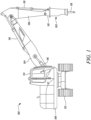
- FIG. 1 an exemplary machine 100 employing a hydraulic hammer 102 (hereinafter referred to as "the hammer 102") is illustrated.
- the machine 100 may be an excavator (shown in FIG. 1 ), a backhoe loader, a skid steer loader, dozer, a motor grader, or any other type of machine.
- the machine 100 may perform work associated with a particular industry including, but not limited to, construction, mining, agriculture, waste management, material handling, and forestry.
- the machine 100 includes linkages, such as a boom 104 and a stick 106.
- the boom 104 is pivotally connected to a frame 108 of the machine 100.
- the stick 106 is pivotally connected to the boom 104.
- a mounting bracket 110 pivotally connects the hammer 102 to the stick 106.
- the hammer 102 may replace an excavator bucket.
- the machine 100 includes a drive system 112, such as tracks, for propelling the machine 100.
- the frame 108 is rotatable about a vertical axis (not shown) with respect to the drive system 112.
- the machine 100 further includes an operator cab 114 having user interface devices for controlling the boom 104, the stick 106, the drive system 112, and the hammer 102.
- One or more hydraulic cylinders 116 may raise, lower, and/or swing the boom 104, the stick 106, and the mounting bracket 110 to correspondingly raise, lower, and/or swing the hammer 102.
- the hammer 102 includes a work tool 118 that may be operated to break up or demolish hard objects, such as rocks, concrete, asphalt, frozen ground, and other materials. It is contemplated that the work tool 118 may include any tool capable of use with the hammer 102. In one embodiment, work tool 118 may include a chisel bit. Further, the hammer 102 may be powered hydraulically, pneumatically, or a combination thereof for actuation of the work tool 118.
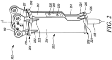
- FIG. 2 illustrates a perspective view of the hammer 102.
- the hammer 102 includes a housing 202 that encloses one or more components of the hammer 102.
- the housing 202 defines a longitudinal axis 'L' along its length. Further, the housing 202 defines a top end 204 and a bottom end 206 with respect to the longitudinal axis 'L'.
- the housing 202 includes a top flange 208 at the top end 204 and a bottom flange 210 at the bottom end 206.
- the top flange 208 is detachably coupled to the mounting bracket 110 via multiple fasteners 211. Further, the work tool 118 extends through the bottom flange 210.
- the housing 202 also includes a front external wall 212 (hereinafter referred to as "the external wall 212"), a pair of side walls 214 disposed opposite to one another, and a rear wall 215 (shown in FIGS. 5 and 8 ) disposed opposite to the external wall 212.
- the external wall 212 defines a front opening 216 (shown in FIG. 3 ) extending therethrough.
- the external wall 212 is located between the side walls 214. Further, the side walls 214 may extend beyond the external wall 212.
- the front opening 216 is covered by a dust cover 218 that defines a pair of cover holes 220. Each of the cover holes 220 may receive a fluid conduit (not shown) therethrough.
- the fluid conduits may provide supply and discharge paths for a working fluid of the hammer 102.
- the housing 202 further includes a pair of top reinforcing portions 222 connected to the top flange 208 and each of the side walls 214.
- the top reinforcing portions 222 may be welded to the top flange 208 and the corresponding side wall 214.
- Each of the top reinforcing portions 222 may have a substantially triangular shape.
- Each of the side walls 214 includes a side handling portion 224 connected to the bottom flange 210.
- a bottom handling portion 226 is further connected to the external wall 212 and the bottom flange 210.
- the bottom handling portion 226 may be welded to the external wall 212 and the bottom flange 210.
- Each of the side and bottom handling portions 224, 226 may have a substantially triangular shape.
- the side and bottom handling portions 224, 226 may point towards the operator cab 114 (shown in FIG. 1 ) of the
- the housing 202 may be connected to each other by various methods, such as welding, brazing, adhesives, mechanical fasteners, and the like.
- the housing 202 may include a one-piece configuration.
- the housing 202 may be made of a metal, an alloy, a plastic, a composite, or any other suitable material.
- FIG. 3 illustrates an exploded view of the hammer 102.
- the hammer 102 includes a power cell 302 that is slidably and removably received within the housing 202.
- the power cell 302 may be slidably received within or removed from the housing 202 along an axial direction 'D'.
- the axial direction 'D' may be substantially parallel to the longitudinal axis ⁇ L' of the housing 202.
- the power cell 302 includes a main housing 304 and a valve assembly 306.
- the main housing 304 defines a first end 307 and a second end 308 opposite to the first end 307.
- the main housing 304 has a substantially rectangular cross-section.
- the main housing 304 may have any other suitable shape as per application requirements.
- the main housing 304 may enclose one or more working components of the power cell 302 for actuating the work tool 118 (shown in FIG. 2 ).
- power cell 302 may include a piston 502 (shown schematically in FIG. 4 ) disposed inside the main housing 304 and other components (not shown).
- the piston 502 may reciprocate inside the main housing 304 during operation of the hammer 102.
- the power cell 302 may further include a bottom part 310 extending from the second end 308 of the housing 202.
- the work tool 118 may extend from the bottom part 310. Further, the work tool 118 may be operatively connected to the power cell 302 at the bottom part 310. In an embodiment, the bottom part 310 may have a hollow cylindrical shape.
- the power cell 302 further includes multiple nut and bolt assemblies 312 that project from the first end 307 of the main housing 304. The nut and bolt assemblies 312 may retain various components of the power cell 302 within the main housing 304.
- the valve assembly 306 extends from a side 314 of the main housing 304. Specifically, the valve assembly 306 may extend transversely from the side 314 of the main housing 304. The valve assembly 306 may regulate flow of the working fluid to and from the power cell 302 in order to actuate the piston 502. The valve assembly 306 may therefore constitute an external valve assembly of the power cell 302, i.e., the valve assembly 306 is disposed externally to the main housing 304.
- the valve assembly 306 includes a main portion 316 and a pair of securing members 318 disposed at opposite ends of the main portion 316. The main portion 316 may form a valve housing and encloses one or more components of the valve assembly 306.
- the main portion 316 may be connected to the main housing 304 of the power cell 302 via multiple first fasteners 320. Further, each of the securing member 318 in cooperation with multiple second fasteners 322 may retain various components within the main portion 316 of the valve assembly 306.
- the valve assembly 306 further includes a pair of fluid connectors 324 disposed on the main portion 316. The fluid connectors 324 may connect with corresponding fluid conduits for intake and discharge of the working fluid from the valve assembly 306.
- the main housing 304 of the power cell 302 further defines multiple apertures 326 around the valve assembly 306. The multiple apertures 326 may receive a pair of wear plates 602.
- the wear plates 602 are at least partially disposed around the valve assembly 306 of the power cell 302.
- the housing 202 further includes an internal wall 402 spaced apart from the external wall 212.
- the internal wall 402 defines a cutout 404.
- the valve assembly 306 is at least partially received within the cutout 404 upon insertion of the power cell 302 within the housing 202. Further, the valve assembly 306 extends through the cutout 404 towards the external wall 212 upon insertion of the power cell 302 within the housing 202.
- the cutout 404 is U-shaped. However, the cutout 404 may have any other alternative shape based on the shape of the valve assembly 306.
- the cutout 404 and the front opening 216 may be substantially aligned with each other such that the fluid conduits received through the cover holes 220 (shown in FIG. 2 ) of the dust cover 218 may be attachable to the corresponding fluid connectors 324 of the valve assembly 306.
- the external wall 212 along with the dust cover 218 may therefore act as a cover for the valve assembly 306.
- the housing 202 further defines a house opening 406 originating at the top end 204 for receiving the power cell 302 within the housing 202.
- the house opening 406 includes a first portion 408 and a second portion 410 adjacent to the fist portion 408.
- the first portion 408 may receive the main housing 304 of the power cell 302.
- the second portion 410 may receive the valve assembly 306 of the power cell 302.
- the first and second portions 408, 410 of the house opening 406 may extend at least partially along the length of the housing 202.
- Each of the first portion 408 and the second portion 410 has a substantially rectangular shape. However, an area of the first portion 408 is larger than an area of the second portion 410.
- the top flange 208 further defines multiple flange apertures 411.
- the mounting bracket 110 also defines corresponding bracket apertures 412.
- the flange apertures 411 and the corresponding bracket apertures 412 receive the corresponding fasteners 211 for removably securing the mounting bracket 110 to the top flange 208 of the housing 202.
- the hammer 102 further includes a top buffer 414 that is disposed proximate to the top end 204 of the housing 202.
- the top buffer 414 may be retained between the mounting bracket 110 and the top flange 208 of the housing 202.
- the top buffer 414 may further rest on a top surface 328 of the main housing 304 of the power cell 302.
- the top buffer 414 includes multiple recessed portions 416 for accommodating the nut and bolt assemblies 312 extending from the top surface 328 of the power cell 302.
- the top buffer 414 further defines a hole 418 extending therethrough.
- the cutout 404 may allow the power cell 302 to be easily inserted into or removed from the housing 202.
- the valve assembly 306 may slide into the cutout 404 upon insertion of the power cell 302 into the housing 202.
- the mounting bracket 110 may have to be disconnected and removed from the top flange 208 of the housing 202.
- the top buffer 414 which rests on the top surface 328 of the power cell 302 may be easily removed without using any tools.
- the power cell 302 including the valve assembly 306 may be then slidably removed from the housing 202.
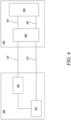
- FIG. 4 shows a schematic view of the power cell 302.
- the power cell 302 includes the piston 502 that reciprocates within the main housing 304.
- the piston 502 may further impact the work tool 118 (shown in FIG. 2 ) during operation of the hammer 102.
- the piston 502 may be actuated by a controlled flow of the working fluid to and from the power cell 302.
- the valve assembly 306 may regulate the flow of the working fluid to one or more fluid chambers (not shown) associated with the piston 502 via fluid passages 504 and 506.
- the valve assembly 306 may provide pressurized working fluid to drive the piston 502 towards the work tool 118 during a work stroke and to return the piston 502 during a return stroke.
- the valve assembly 306 may include one or more valves (not shown) to control the flow of the working fluid.
- the valves may be mechanically operated valves, electronically controlled valves, pilot operated valves, and so forth.
- the valve assembly 306 is further fluidly connected to a hydraulic system 508 of the machine 100 (shown in FIG. 1 ) via fluid lines 510 and 512.
- the valve assembly 306 may be fluidly connected to the fluid lines 510 and 512 via the fluid connectors 324.
- the hydraulic system 508 may include a tank 514 and a pump 516.
- the pump 516 is in fluid communication with the tank 514.
- the hydraulic system 508 may be powered by a power source (not shown) of the machine 100.
- the hydraulic system 508 may also include additional components (not shown), for example, one or more valves, filters, sensors, and so forth.
- the fluid line 510 may supply pressurized working fluid to the valve assembly 306 from the pump 516.
- the fluid line 512 may provide a return path of the working fluid from the valve assembly 306 to the tank 514.
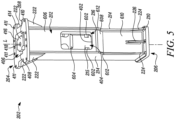
- FIG. 5 illustrates a perspective view of the housing 202.
- the wear plates 602 may be disposed around the cutout 404 defined by the internal wall 402.
- Each of the wear plates 602 is coupled to the power cell 302 (shown in FIG. 3 ).
- each of the wear plates 602 may be detachably coupled to the internal wall 402 of the housing 202 by various methods, such as fasteners, pegs, a snap-fit connection, and so forth.
- a middle buffer 604 of the hammer 102 is also disposed within the housing 202.
- the middle buffer 604 may be coupled to the rear wall 215 and/or side walls 214 of the housing 202.
- the middle buffer 604 may have any suitable shape as per application requirements.
- the top buffer 414 is disposed proximate to the top end 204 of the housing 202.
- the external wall 212 is spaced apart from the internal wall 402. Further, the external wall 212 includes a top portion 606, an inclined portion 608, and a bottom portion 610.
- the top portion 606 is proximal to the top end 204 of the housing 202.
- the bottom portion 610 is proximal to the bottom end 206 of the housing 202.
- the bottom handling portion 226 is further located in the bottom portion 610 of the external wall 212.
- the inclined portion 608 is disposed between the top portion 606 and the bottom portion 610.
- the top portion 606 and the bottom portion 610 may extend substantially parallel to the longitudinal axis 'L' of the housing 202.
- the inclined portion 608 may be inclined at an angle with respect to the longitudinal axis 'L'.
- Each of the side walls 214 also includes a sloped portion 612 located on a side of the inclined portion 608.
- Each of the sloped portions 612 may also be inclined at an angle with respect to the longitudinal axis 'L'
- FIG. 6 illustrates a partial perspective view of the housing 202 with a part of the external wall 212 removed. Specifically, the top and inclined portions 606, 608 of the external wall 212 have been removed for illustrative purposes.
- the internal wall 402 includes a pair of elongate portions 702 extending from an upper edge 704.
- the elongate portions 702 and the upper edge 704 together define the cutout 404.
- Each of the elongate portions 702 may have a rectangular shape.
- the interface between each of the elongate portions 702 and the upper edge 704 may be rounded to provide the cutout 404 with a U-shape.
- a pair of lateral members 706 (only one shown in FIG.
- each of the lateral members 706 may extend transversely from the internal wall 402 towards the rear wall 215. Specifically, each of the lateral members 706 may extend from the corresponding elongate portion 702 of the internal wall 402. The lateral members 706 may guide the valve assembly 306 (shown in FIG. 3 ) during insertion or removal of the power cell 302 from the housing 202.
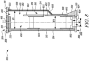
- FIGS. 7 and 8 illustrate different sectional views of the housing 202.
- the top buffer 414 is disposed at the top end 204 of the housing 202.
- a pair of bottom buffers 802 of the hammer 102 is disposed proximate to the bottom end 206 of the housing 202.
- the hammer 102 may have any number of bottom buffers 802 as per application requirements.
- Each of the bottom buffers 802 may be disposed adjacent to a support portion 804 of the housing 202.
- the support portion 804 is further disposed on the bottom flange 210 of the housing 202.
- the bottom buffers 802 are disposed opposite to each other.
- the bottom buffers 802 may be removably coupled to one or more parts of the housing 202 by various methods, such as mechanical fasteners, a snap-fit connection, and the like.
- One of the bottom buffers 802 may be removably coupled to the rear wall 215.
- the other bottom buffer 802 may be removably coupled to the bottom portion 610 of the external wall 212.
- Each of the bottom buffers 802 may have any suitable shape as per application requirements. In an embodiment, each of the bottom buffers 802 may be chamfered at both top and bottom ends.
- the middle buffer 604 is disposed between the top buffer 414 and one of the bottom buffers 802 with respect to the longitudinal axis 'L' of the housing 202.
- the middle buffer 604 may be removably coupled to the rear wall 215 of the housing 202. Further, the middle buffer 604 may be located opposite to the cutout 404 and the wear plates 602 (only one shown in FIG. 8 ). In an embodiment, the middle buffer 604 may be chamfered at both top and bottom ends. In another embodiment, the middle buffer 604 and each of the bottom buffers 802 may have a substantially similar configuration.
- the top, middle, and bottom buffers 414, 604, 802 and the wear plates 602 may form a buffer system of the hammer 102.
- Each of the top, middle, and bottom buffers 414, 604, 802 may act as a sacrificial material, and prevent the components of the power cell 302 from being subjected to wear and abrasion during operation of the hammer 102.
- the top, middle, and bottom buffers 414, 604, 802 may further isolate at least a part of the power cell 302 from the housing 202.
- the top, middle, and bottom buffers 414, 604, 802 may isolate the main housing 304 of the power cell 302 from the housing 202.
- the top, middle, and bottom buffers 414, 604, 802 may also protect inner surfaces of the housing 202 by presenting a sacrificial surface.
- each of the top, middle, and bottom buffers 414, 604, 802 may be made of a non-metallic material, for example, but not limited to, rubber, urethane, nylon, ultra-high-molecular-weight polyethylene (UHMW), and so forth.
- the housing 202 further includes a bottom opening 806 disposed at the bottom end 206.
- the bottom opening 806 is defined by the bottom flange 210 and extends therethrough.
- the support portion 804 also defines a support opening 808 extending therethrough.
- the support opening 808 may be axially aligned with the bottom opening 806 of the bottom flange 210.
- the work tool 118 (shown in FIG. 2 ) extends through the bottom opening 806.
- the side walls 214 extend beyond the external wall 212 along a direction that is perpendicular to the longitudinal axis ⁇ L' of the housing 202.
- the front opening 216 may be substantially aligned with the cutout 404.
- the side walls 214 may also extend beyond the rear wall 215 along a direction that is perpendicular to the longitudinal axis ⁇ L' of the housing 202.
- the rear wall 215 may be disposed between the side walls 214.
- the housing 202 further defines a hollow volume for slidably receiving the power cell 302 therein.
- the house opening 406 may extend at least partially along the length of the housing 202 to define the hollow volume.
- the first portion 408 of the house opening 406 may extend from the top end 204 of the housing 202 to the support portion 804.
- the main housing 304 (shown in FIG. 3 ) of the power cell 302 is received within the first portion 408.
- the valve assembly 306 may be slidably inserted or removed through the second portion 410 of the house opening 406.
- the second portion 410 may extend from the top end 204 of the housing 202 to an upper edge of the inclined portion 608 of the external wall 212.
- a width of the hollow volume defined by the housing 202 varies along the longitudinal axis 'L'.
- the hollow volume may have a first width 'W1' till the upper edge of the inclined portion 608.
- the hollow volume may have a second width 'W2' from a lower edge of the inclined portion 608 to the support portion 804.
- the first width 'W1' may be larger than the second width 'W2'.
- the first width 'W I' may accommodate both the main housing 304 and the valve assembly 306 of the power cell 302.
- the second width 'W2' may accommodate only the main housing 304 of the power cell 302.
- the inclined portion 608 of the external wall 212 and the sloped portions 612 of the side walls 214 may act as a transition region between the first width 'W1' and the second width 'W2'. Further, the support opening 808 has a third width 'W3'. The support opening 808 may at least partially receive the bottom part 310 (shown in FIG. 3 ) of the power cell 302.
- the valve assembly 306 Upon insertion within the housing 202, the valve assembly 306 extends through the cutout 404 towards the external wall 212. Specifically, the valve assembly 306 extends into a space 810 defined between the internal wall 402 and the external wall 212.
- the internal wall 402 further extends upwards from the lower edge of the inclined portion 608 of the external wall 212.
- the internal wall 402 may be integral with the bottom portion 610 of the external wall 212. In another embodiment, the internal wall 402 may be joined to the bottom portion 610.
- FIG. 9 illustrates the power cell 302 being partially inserted into the housing 202.
- the power cell 302 may be inserted substantially parallel to the axial direction 'D'.
- the main housing 304 of the power cell 302 defines two pairs of the apertures 326.
- the apertures 326 are disposed around the valve assembly 306. Specifically, one of the pair of apertures 326 are disposed on one side of the valve assembly 306, while the other pair of apertures 326 are disposed on the opposite side.
- Each of the pair of apertures 326 are coupled to the corresponding wear plate 602 (shown in FIG. 3 ).
- the apertures 326 may be drilled into the main housing 304.
- the cutout 404 may allow the valve assembly 306 to be inserted into or removed from the housing 202. Further, the valve assembly 306 is at least partially received in the cutout 404 upon insertion within the housing 202.
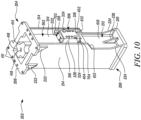
- FIG. 10 illustrates the power cell 302 fully inserted within the housing 202. A part of the external wall 212 has been removed for the purpose of illustration.
- the valve assembly 306 is at least partially received within the cutout 404. Further, the valve assembly 306 may extend through the cutout 404.
- the top buffer 414 is disposed on the power cell 302.
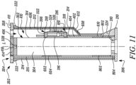
- FIG. 11 illustrates a sectional view of the power cell 302 fully inserted within the housing 202.
- Various internal components of the power cell 302 have been omitted for the purpose of illustration.
- the main housing 304 of the power cell 302 is received within the first portion 408 of the house opening 406.
- the valve assembly 306 is at least partially received within the cutout 404 and extends into the space 810 defined between the internal wall 402 and the external wall 212.
- the bottom part 310 is at least partially received within the support opening 808 of the support portion 804.
- the top buffer 414 is disposed on the top surface 328 of the main housing 304.
- the middle and bottom buffers 604, 802 abut the main housing 304 of the power cell 302. In an embodiment, the middle and bottom buffers 604, 802 may be removably coupled to the main housing 304.
- FIG. 12 illustrates a front view of the valve assembly 306.
- the wear plates 602 at least partially surround the valve assembly 306 on opposite sides.
- Each of the wear plates 602 includes an elongate section 902 and a pair of lateral sections 904 extending from opposite ends of the elongate section 902.
- the pair of lateral sections 904 may be oriented substantially perpendicular to the elongate section 902.
- Each of the lateral sections 904 includes a projecting portion 906 that is adapted to be removably received within the corresponding aperture 326 (shown in FIG. 9 ) of the main housing 304.
- each of the pair of wear plates 602 includes a pair of the projecting portions 906 adapted to be removably received within the corresponding apertures 326 of the main housing 304 of the power cell 302.
- the wear plates 602 may be connected to the power cell 302 prior to insertion within the housing 202.
- the wear plates 602 may be connected to the power cell 302 upon insertion of the power cell 302 within the housing 202.
- the wear plates 602 may be removably attached to the internal wall 402 (shown in FIG. 6 ) of the housing 202.
- the main portion 316 of the valve assembly 306 further includes a pair of longitudinal edges 330 opposite to each other and a pair of lateral edges 332 opposite to each other.
- the elongate section 902 of each of the wear plates 602 is proximal to the corresponding longitudinal edge 330 of the main portion 316. Further, the elongate section 902 of each of the wear plates 602 may be oriented substantially parallel to the corresponding longitudinal edge 330 of the main portion 316.
- the lateral sections 904 of each of the wear plates 602 are proximal to the corresponding lateral edges 332 of the main portion 316. Further, the lateral sections 904 of each of the wear plates 602 are oriented substantially parallel to the corresponding lateral edges 332 of the main portion 316.
- the wear plates 602 may protect the valve assembly 306 from wear and abrasion during operation of the hammer 102. Further, the wear plates 602 may retain the valve assembly 306 in place.
- Each of wear plates 602 may be made of a non-metallic material, for example, but not limited to, rubber, urethane, nylon, ultra-high-molecular-weight polyethylene (UHMW), and so forth.
- the main portion 316 of the valve assembly 306 further defines six first apertures 908 and two second apertures 910. Three of the first apertures 908 and one of the second apertures 910 are arranged in a column proximal to one of the longitudinal edges 330 of the main portion 316. Similarly, the other three of the first apertures 908 and the other second aperture 910 are arranged in another column proximal to the other longitudinal edge 330 of the main portion 316. Further, the arrangement of the first apertures 908 and the second aperture 910 in one column is reversed with respect to the other column. Specifically, the second aperture 910 is located at the top in one column, while the second aperture 910 is located at the bottom in another column.
- Each of the first apertures 908 receives the corresponding first fastener 320.
- the first fasteners 320 may couple the main portion 316 of the valve assembly 306 to the main housing 304 of the power cell 302.
- Each of the second apertures 910 receives the corresponding fluid connector 324.
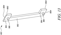
- FIG. 13 illustrates a perspective view of one of the wear plates 602.
- the elongate section 902 may have a rectangular shape.
- Each lateral section 904 of the wear plate 602 includes a chamfered region 1002 that extends from a corresponding end 1004 of the wear plate 602.
- the projecting portions 906 are located on a surface that faces the main housing 304 (shown in FIG. 3 ) of the power cell 302. Further, the chamfered regions 1002 and the projecting portions 906 are located on opposite surfaces.
- Each of the projecting portions 906 may have a cylindrical shape. Further, each of the projecting portions 906 may be embodied as pegs that are removably received within the corresponding aperture 326 (shown in FIG. 9 ) of the power cell 302.
- FIGS. 14A and 14B illustrate different views of a buffer member 1402.
- the buffer member 1402 may act as both the middle buffer 604 and each of the bottom buffers 802 (shown in FIG. 8 ) of the hammer 102.
- the buffer member 1402 includes a top buffer end 1404 and a bottom buffer end 1406.
- the buffer member 1402 includes chamfered portions 1403 at each of the top and bottom buffer ends 1404, 1406.
- the buffer member 1402 further includes a main body 1408 defining a pair of lateral recesses 1410 opposite to each other.
- the buffer member 1402 further includes a pair of lateral projections 1412 and a middle projection 1414 extending from the main body 1408.
- the middle projection 1414 and each of the lateral projections 1412 define a top recess 1416 between them.
- the present disclosure relates to the hammer 202 with the valve assembly 306 that is externally mounted on the power cell 302.
- the hammer includes the housing 202 that defines the cutout 404.
- the cutout 404 may allow the power cell 302 to be easily inserted into or removed from the housing 202.
- the power cell 302 may have to be removed from the housing 202 for servicing and/or replacement.
- the valve assembly 306 may slide into the cutout 404 upon insertion of the power cell 302 into the housing 202.
- the mounting bracket 110 may have to be disconnected and removed from the top flange 208 of the housing 202.
- the top buffer 414 which freely rests on the top surface 328 of the power cell 302 may be easily removed without using any tools.
- the power cell 302 including the valve assembly 306 may be then slidably removed from the housing 202. After removal of the mounting bracket 110, the power cell 302 may therefore be removed from the housing 202 without requiring the disconnection of additional parts using tools. This may reduce downtime and requirement of tools to service and/or replace the power cell 302.
- the wear plates 602 may also protect the valve assembly 306 from wear and abrasion during operation of the hammer 202.
- the wear plates 602 may be easily attached to or removed from the power cell 302.
Landscapes
- Engineering & Computer Science (AREA)
- Mechanical Engineering (AREA)
- Physics & Mathematics (AREA)
- Fluid Mechanics (AREA)
- Mining & Mineral Resources (AREA)
- Civil Engineering (AREA)
- General Engineering & Computer Science (AREA)
- Structural Engineering (AREA)
- Percussive Tools And Related Accessories (AREA)
- Portable Power Tools In General (AREA)
Claims (8)
- Hydraulikhammer (102), umfassend:ein Gehäuse (202), das einen Ausschnitt (404) definiert;eine Leistungszelle (302), die innerhalb des Gehäuses (202) verschiebbar aufgenommen ist, wobei die Leistungszelle (302) eine Ventilanordnung (306) einschließt, die sich von einer Seite (314) der Leistungszelle (302) erstreckt, wobei die Ventilanordnung (306) mindestens teilweise innerhalb des Ausschnitts (404) des Gehäuses (202) aufgenommen ist; undein Paar von Verschleißplatten (602), die mindestens teilweise um die Ventilanordnung (306) der Leistungszelle (302) herum eingerichtet sind; dadurch gekennzeichnet, dassjedes Paar von Verschleißplatten (602) mit der Leistungszelle (302) gekoppelt ist.
- Hydraulikhammer (102) nach Anspruch 1, wobei der Ausschnitt (404) U-förmig ist.
- Hydraulikhammer (102) nach Anspruch 1, wobei der Ausschnitt (404) durch eine Innenwand (402) des Gehäuses (202) definiert ist.
- Hydraulikhammer (102) nach Anspruch 3, wobei das Gehäuse (202) ferner eine Außenwand (212) umfasst, die von der Innenwand (402) beabstandet ist, und wobei sich die Ventilanordnung (306) durch den Ausschnitt (404) zu der Außenwand (212) erstreckt.
- Hydraulikhammer (102) nach Anspruch 1, wobei jedes des Paares von Verschleißplatten (602) ein Paar von vorstehenden Abschnitten (906) einschließt, die angepasst sind, um innerhalb entsprechender Öffnungen (326) der Leistungszelle (302) abnehmbar aufgenommen zu werden.
- Hydraulikhammer (102) nach Anspruch 1, ferner umfassend einen oberen Puffer (414), der nahe einem oberen Ende (204) des Gehäuses (202) eingerichtet ist.
- Hydraulikhammer (102) nach Anspruch 6, ferner umfassend einen unteren Puffer (802), der nahe einem unteren Ende (206) des Gehäuses (202) eingerichtet ist.
- Hydraulikhammer (102) nach Anspruch 7, ferner umfassend einen mittleren Puffer (604), der zwischen dem oberen Puffer (414) und dem unteren Puffer (802) eingerichtet ist.
Applications Claiming Priority (1)
| Application Number | Priority Date | Filing Date | Title |
|---|---|---|---|
| US16/011,001 US11027403B2 (en) | 2018-06-18 | 2018-06-18 | Hydraulic hammer |
Publications (2)
| Publication Number | Publication Date |
|---|---|
| EP3584037A1 EP3584037A1 (de) | 2019-12-25 |
| EP3584037B1 true EP3584037B1 (de) | 2024-10-09 |
Family
ID=66647189
Family Applications (1)
| Application Number | Title | Priority Date | Filing Date |
|---|---|---|---|
| EP19176326.7A Active EP3584037B1 (de) | 2018-06-18 | 2019-05-23 | Hydraulischer hammer |
Country Status (3)
| Country | Link |
|---|---|
| US (1) | US11027403B2 (de) |
| EP (1) | EP3584037B1 (de) |
| CN (1) | CN110614611B (de) |
Families Citing this family (8)
| Publication number | Priority date | Publication date | Assignee | Title |
|---|---|---|---|---|
| CN111519687B (zh) * | 2020-04-30 | 2021-06-15 | 烟台艾迪精密机械股份有限公司 | 一种静音式破碎锤减震组件的装配方法 |
| CN212896564U (zh) * | 2020-06-17 | 2021-04-06 | 台州贝力特机械有限公司 | 一种液压破碎锤的外壳结构 |
| US11981013B2 (en) * | 2020-11-23 | 2024-05-14 | Caterpillar Inc. | Dust cover for hammer work tool |
| US11752612B2 (en) * | 2020-11-23 | 2023-09-12 | Caterpillar Inc. | Dust suppression system for hammers |
| US20220362897A1 (en) * | 2021-05-12 | 2022-11-17 | Caterpillar Inc. | Cover for a hammer tool and systems, assemblies, and methods thereof |
| KR102299173B1 (ko) * | 2021-05-28 | 2021-09-09 | 대모 엔지니어링 주식회사 | 유압식 2단 스트로크 유압브레이커 |
| US12534871B2 (en) * | 2022-09-30 | 2026-01-27 | Caterpillar Inc. | Rods for engaging a tool of a hammer within a housing of the hammer |
| USD1089324S1 (en) * | 2023-02-24 | 2025-08-19 | Sandvik Mining And Construction Oy | Rock breaker |
Citations (1)
| Publication number | Priority date | Publication date | Assignee | Title |
|---|---|---|---|---|
| US20120152581A1 (en) * | 2010-12-18 | 2012-06-21 | Caterpillar Inc. | Hammer side buffer |
Family Cites Families (42)
| Publication number | Priority date | Publication date | Assignee | Title |
|---|---|---|---|---|
| US3969984A (en) * | 1974-11-11 | 1976-07-20 | Hydroacoustics Inc. | Hydroacoustic apparatus and valving mechanisms for use therein |
| US4474248A (en) * | 1981-04-23 | 1984-10-02 | Giovanni Donadio | Hydraulic demolishing rock drill |
| US4552227A (en) * | 1981-12-17 | 1985-11-12 | The Stanley Works | Reciprocating linear fluid motor |
| ATE20647T1 (de) * | 1982-01-22 | 1986-07-15 | Mauro Vitulano | Steuerventil fuer den hin- und herbewegenden kolben einer hydraulischen schlagvorrichtung, insbesondere fuer einen hydraulischen hammer. |
| US4653596A (en) * | 1983-04-05 | 1987-03-31 | Institut Gornogo Dela Sibirskogo Otdelenia An Sssr | Percussive air tool |
| JPS59209775A (ja) * | 1983-05-13 | 1984-11-28 | 株式会社ランドマ−クウエスト | さく岩機 |
| US4906049A (en) | 1988-11-28 | 1990-03-06 | N. P. K. Construction Equipment, Inc. | Ripper using a hydraulic hammer and a method for making the improvement |
| CA2036883C (en) * | 1991-02-22 | 2003-12-02 | Roger F. Masse | Drill head with integral impact hammers |
| ZA946878B (en) * | 1993-09-08 | 1995-04-24 | Keech Castings Australia | Hydraulic fastening device and method |
| JPH1034563A (ja) | 1996-07-17 | 1998-02-10 | Teisaku:Kk | 打撃工具のブラケット |
| KR100260309B1 (ko) * | 1997-06-11 | 2000-07-01 | 최해성 | 유압헤머 |
| US6058632A (en) * | 1997-11-07 | 2000-05-09 | Hawkins; Peter Arthur Taylor | Tool holder with percussion member |
| US5944120A (en) * | 1997-11-10 | 1999-08-31 | Caterpillar Inc. | Hydraulic hammer assembly having low vibration characteristics |
| NZ522158A (en) * | 2002-10-21 | 2005-05-27 | Rocktec Ltd | A locking mechanism |
| US6893228B2 (en) * | 2002-11-22 | 2005-05-17 | Caterpillar Inc | Axial piston pump with fluid bearing arrangement |
| JP2005001063A (ja) | 2003-06-12 | 2005-01-06 | Teisaku:Kk | ブレーカ用ブラケット |
| JP4559156B2 (ja) * | 2004-08-18 | 2010-10-06 | 株式会社東洋空機製作所 | ブレーカ取付用ブラケット |
| KR200369452Y1 (ko) | 2004-09-21 | 2004-12-04 | 주식회사 코막 | 자동윤활공급부와 공압공급부가 구비된 유압 타격식파쇄장치 |
| US7681664B2 (en) * | 2008-03-06 | 2010-03-23 | Patterson William N | Internally dampened percussion rock drill |
| US8733468B2 (en) * | 2010-12-02 | 2014-05-27 | Caterpillar Inc. | Sleeve/liner assembly and hydraulic hammer using same |
| US8672052B2 (en) * | 2010-12-14 | 2014-03-18 | Caterpillar Inc. | Demolition hammer with reversible housing and interchangeable wear plate arrangement |
| US8708061B2 (en) * | 2010-12-14 | 2014-04-29 | Caterpillar Inc. | Lower damper for demolition hammer |
| EP2877639A4 (de) * | 2012-07-18 | 2016-04-06 | Terminator Ip Ltd | Dämpfungsgleitschienen |
| ITMO20120194A1 (it) * | 2012-08-02 | 2014-02-03 | Socomec Societa Costruzioni Mecc Aniche Societa | Martello demolitore a resistenza ottimizzata. |
| US9217341B2 (en) * | 2013-08-15 | 2015-12-22 | Caterpillar Inc. | Lubrication system for tool |
| JP6155153B2 (ja) * | 2013-09-26 | 2017-06-28 | 古河ロックドリル株式会社 | 油圧ブレーカ |
| JP2015160283A (ja) | 2014-02-27 | 2015-09-07 | 古河ロックドリル株式会社 | 油圧ブレーカ用ブラケットおよびこれを備える油圧ブレーカ |
| JP6426442B2 (ja) | 2014-11-14 | 2018-11-21 | 株式会社小松製作所 | チゼル用鋼およびチゼル |
| KR101686126B1 (ko) | 2014-12-26 | 2016-12-13 | 장명수 | 유압에 의해 구동되는 평판형 스풀 작동장치 |
| KR101570692B1 (ko) * | 2015-01-07 | 2015-11-20 | 주식회사 에이와이중공업 | 유압 브레이커 |
| US20160199969A1 (en) * | 2015-01-12 | 2016-07-14 | Caterpillar Inc. | Hydraulic hammer having variable stroke control |
| KR20160103316A (ko) | 2015-02-24 | 2016-09-01 | 전준태 | 개선된 브레이커 |
| US20160303728A1 (en) * | 2015-04-17 | 2016-10-20 | Caterpillar Inc. | Hammer Buffer |
| US10201894B2 (en) * | 2015-09-14 | 2019-02-12 | Caterpillar Inc. | Collet hydraulic hammer bushing |
| US10076831B2 (en) * | 2015-09-24 | 2018-09-18 | Caterpillar Inc. | Buffer system for hydraulic hammer |
| US10029358B2 (en) * | 2015-11-13 | 2018-07-24 | Caterpillar Inc. | Hydraulic hammer with clearance control system |
| US20170157759A1 (en) * | 2015-12-08 | 2017-06-08 | Caterpillar Inc. | Dust Clearing Tool |
| US10094754B2 (en) * | 2015-12-11 | 2018-10-09 | Caterpillar Inc. | Pressure indicator for hydraulic hammer |
| KR101804790B1 (ko) * | 2016-03-15 | 2017-12-05 | (주)대동이엔지 | 유압 브레이커 |
| US10286535B2 (en) * | 2016-03-30 | 2019-05-14 | Caterpillar Inc. | Valve body charge lock |
| US10226857B2 (en) * | 2016-10-19 | 2019-03-12 | Caterpillar Inc. | Reversible bushing |
| US20170036336A1 (en) * | 2016-10-25 | 2017-02-09 | Caterpillar Inc. | Hammer assembly |
-
2018
- 2018-06-18 US US16/011,001 patent/US11027403B2/en active Active
-
2019
- 2019-05-23 EP EP19176326.7A patent/EP3584037B1/de active Active
- 2019-06-10 CN CN201910496159.XA patent/CN110614611B/zh active Active
Patent Citations (1)
| Publication number | Priority date | Publication date | Assignee | Title |
|---|---|---|---|---|
| US20120152581A1 (en) * | 2010-12-18 | 2012-06-21 | Caterpillar Inc. | Hammer side buffer |
Also Published As
| Publication number | Publication date |
|---|---|
| CN110614611B (zh) | 2024-06-11 |
| EP3584037A1 (de) | 2019-12-25 |
| US11027403B2 (en) | 2021-06-08 |
| CN110614611A (zh) | 2019-12-27 |
| US20190381645A1 (en) | 2019-12-19 |
Similar Documents
| Publication | Publication Date | Title |
|---|---|---|
| EP3584037B1 (de) | Hydraulischer hammer | |
| EP2652209B1 (de) | Schlaghammer mit umkehrbarem gehäuse und austauschbarer verschleissplattenanordnung | |
| EP2652210B1 (de) | Gesteinsklammergreifer für einen schlaghammer | |
| WO2012082984A1 (en) | Hammer side buffer | |
| WO2024151467A1 (en) | Power cell for a hydraulic hammer and method of assembling a hydraulic hammer power cell | |
| US20160184982A1 (en) | Demolition Hammer with Wear Plate System Having Debris Channels | |
| CN119866256A (zh) | 用于液压锤的工具 | |
| AU2021381293B2 (en) | Dust suppression system for hammers | |
| US11981013B2 (en) | Dust cover for hammer work tool | |
| CN113280009A (zh) | 用于在机器的流体系统中传送流体的系统 | |
| EP3567165A1 (de) | Felsklaue für einen abbruchhammer | |
| JP7736610B2 (ja) | クラムシェルバケット | |
| KR20250073420A (ko) | 해머의 하우징 내에 해머 툴을 체결하기 위한 로드 | |
| AU2024244030A1 (en) | Hammer piston |
Legal Events
| Date | Code | Title | Description |
|---|---|---|---|
| PUAI | Public reference made under article 153(3) epc to a published international application that has entered the european phase |
Free format text: ORIGINAL CODE: 0009012 |
|
| STAA | Information on the status of an ep patent application or granted ep patent |
Free format text: STATUS: THE APPLICATION HAS BEEN PUBLISHED |
|
| AK | Designated contracting states |
Kind code of ref document: A1 Designated state(s): AL AT BE BG CH CY CZ DE DK EE ES FI FR GB GR HR HU IE IS IT LI LT LU LV MC MK MT NL NO PL PT RO RS SE SI SK SM TR |
|
| AX | Request for extension of the european patent |
Extension state: BA ME |
|
| STAA | Information on the status of an ep patent application or granted ep patent |
Free format text: STATUS: REQUEST FOR EXAMINATION WAS MADE |
|
| 17P | Request for examination filed |
Effective date: 20200625 |
|
| RBV | Designated contracting states (corrected) |
Designated state(s): AL AT BE BG CH CY CZ DE DK EE ES FI FR GB GR HR HU IE IS IT LI LT LU LV MC MK MT NL NO PL PT RO RS SE SI SK SM TR |
|
| STAA | Information on the status of an ep patent application or granted ep patent |
Free format text: STATUS: EXAMINATION IS IN PROGRESS |
|
| 17Q | First examination report despatched |
Effective date: 20220309 |
|
| GRAP | Despatch of communication of intention to grant a patent |
Free format text: ORIGINAL CODE: EPIDOSNIGR1 |
|
| STAA | Information on the status of an ep patent application or granted ep patent |
Free format text: STATUS: GRANT OF PATENT IS INTENDED |
|
| RIC1 | Information provided on ipc code assigned before grant |
Ipc: B25D 17/00 20060101ALI20240307BHEP Ipc: B25D 9/00 20060101ALI20240307BHEP Ipc: E02F 3/96 20060101ALI20240307BHEP Ipc: B25D 17/24 20060101AFI20240307BHEP |
|
| INTG | Intention to grant announced |
Effective date: 20240405 |
|
| GRAS | Grant fee paid |
Free format text: ORIGINAL CODE: EPIDOSNIGR3 |
|
| P01 | Opt-out of the competence of the unified patent court (upc) registered |
Free format text: CASE NUMBER: APP_41890/2024 Effective date: 20240716 |
|
| GRAA | (expected) grant |
Free format text: ORIGINAL CODE: 0009210 |
|
| STAA | Information on the status of an ep patent application or granted ep patent |
Free format text: STATUS: THE PATENT HAS BEEN GRANTED |
|
| AK | Designated contracting states |
Kind code of ref document: B1 Designated state(s): AL AT BE BG CH CY CZ DE DK EE ES FI FR GB GR HR HU IE IS IT LI LT LU LV MC MK MT NL NO PL PT RO RS SE SI SK SM TR |
|
| REG | Reference to a national code |
Ref country code: CH Ref legal event code: EP |
|
| REG | Reference to a national code |
Ref country code: DE Ref legal event code: R096 Ref document number: 602019059941 Country of ref document: DE |
|
| REG | Reference to a national code |
Ref country code: IE Ref legal event code: FG4D |
|
| REG | Reference to a national code |
Ref country code: SE Ref legal event code: TRGR |
|
| REG | Reference to a national code |
Ref country code: LT Ref legal event code: MG9D |
|
| REG | Reference to a national code |
Ref country code: NL Ref legal event code: MP Effective date: 20241009 |
|
| REG | Reference to a national code |
Ref country code: AT Ref legal event code: MK05 Ref document number: 1730077 Country of ref document: AT Kind code of ref document: T Effective date: 20241009 |
|
| PG25 | Lapsed in a contracting state [announced via postgrant information from national office to epo] |
Ref country code: NL Free format text: LAPSE BECAUSE OF FAILURE TO SUBMIT A TRANSLATION OF THE DESCRIPTION OR TO PAY THE FEE WITHIN THE PRESCRIBED TIME-LIMIT Effective date: 20241009 |
|
| PG25 | Lapsed in a contracting state [announced via postgrant information from national office to epo] |
Ref country code: NL Free format text: LAPSE BECAUSE OF FAILURE TO SUBMIT A TRANSLATION OF THE DESCRIPTION OR TO PAY THE FEE WITHIN THE PRESCRIBED TIME-LIMIT Effective date: 20241009 |
|
| PG25 | Lapsed in a contracting state [announced via postgrant information from national office to epo] |
Ref country code: HR Free format text: LAPSE BECAUSE OF FAILURE TO SUBMIT A TRANSLATION OF THE DESCRIPTION OR TO PAY THE FEE WITHIN THE PRESCRIBED TIME-LIMIT Effective date: 20241009 Ref country code: PT Free format text: LAPSE BECAUSE OF FAILURE TO SUBMIT A TRANSLATION OF THE DESCRIPTION OR TO PAY THE FEE WITHIN THE PRESCRIBED TIME-LIMIT Effective date: 20250210 Ref country code: IS Free format text: LAPSE BECAUSE OF FAILURE TO SUBMIT A TRANSLATION OF THE DESCRIPTION OR TO PAY THE FEE WITHIN THE PRESCRIBED TIME-LIMIT Effective date: 20250209 |
|
| PG25 | Lapsed in a contracting state [announced via postgrant information from national office to epo] |
Ref country code: FI Free format text: LAPSE BECAUSE OF FAILURE TO SUBMIT A TRANSLATION OF THE DESCRIPTION OR TO PAY THE FEE WITHIN THE PRESCRIBED TIME-LIMIT Effective date: 20241009 |
|
| PG25 | Lapsed in a contracting state [announced via postgrant information from national office to epo] |
Ref country code: BG Free format text: LAPSE BECAUSE OF FAILURE TO SUBMIT A TRANSLATION OF THE DESCRIPTION OR TO PAY THE FEE WITHIN THE PRESCRIBED TIME-LIMIT Effective date: 20241009 |
|
| PG25 | Lapsed in a contracting state [announced via postgrant information from national office to epo] |
Ref country code: ES Free format text: LAPSE BECAUSE OF FAILURE TO SUBMIT A TRANSLATION OF THE DESCRIPTION OR TO PAY THE FEE WITHIN THE PRESCRIBED TIME-LIMIT Effective date: 20241009 |
|
| PG25 | Lapsed in a contracting state [announced via postgrant information from national office to epo] |
Ref country code: NO Free format text: LAPSE BECAUSE OF FAILURE TO SUBMIT A TRANSLATION OF THE DESCRIPTION OR TO PAY THE FEE WITHIN THE PRESCRIBED TIME-LIMIT Effective date: 20250109 |
|
| PG25 | Lapsed in a contracting state [announced via postgrant information from national office to epo] |
Ref country code: LV Free format text: LAPSE BECAUSE OF FAILURE TO SUBMIT A TRANSLATION OF THE DESCRIPTION OR TO PAY THE FEE WITHIN THE PRESCRIBED TIME-LIMIT Effective date: 20241009 Ref country code: GR Free format text: LAPSE BECAUSE OF FAILURE TO SUBMIT A TRANSLATION OF THE DESCRIPTION OR TO PAY THE FEE WITHIN THE PRESCRIBED TIME-LIMIT Effective date: 20250110 Ref country code: AT Free format text: LAPSE BECAUSE OF FAILURE TO SUBMIT A TRANSLATION OF THE DESCRIPTION OR TO PAY THE FEE WITHIN THE PRESCRIBED TIME-LIMIT Effective date: 20241009 |
|
| PG25 | Lapsed in a contracting state [announced via postgrant information from national office to epo] |
Ref country code: PL Free format text: LAPSE BECAUSE OF FAILURE TO SUBMIT A TRANSLATION OF THE DESCRIPTION OR TO PAY THE FEE WITHIN THE PRESCRIBED TIME-LIMIT Effective date: 20241009 |
|
| PG25 | Lapsed in a contracting state [announced via postgrant information from national office to epo] |
Ref country code: RS Free format text: LAPSE BECAUSE OF FAILURE TO SUBMIT A TRANSLATION OF THE DESCRIPTION OR TO PAY THE FEE WITHIN THE PRESCRIBED TIME-LIMIT Effective date: 20250109 |
|
| PG25 | Lapsed in a contracting state [announced via postgrant information from national office to epo] |
Ref country code: SM Free format text: LAPSE BECAUSE OF FAILURE TO SUBMIT A TRANSLATION OF THE DESCRIPTION OR TO PAY THE FEE WITHIN THE PRESCRIBED TIME-LIMIT Effective date: 20241009 |
|
| PGFP | Annual fee paid to national office [announced via postgrant information from national office to epo] |
Ref country code: DE Payment date: 20250423 Year of fee payment: 7 |
|
| PG25 | Lapsed in a contracting state [announced via postgrant information from national office to epo] |
Ref country code: DK Free format text: LAPSE BECAUSE OF FAILURE TO SUBMIT A TRANSLATION OF THE DESCRIPTION OR TO PAY THE FEE WITHIN THE PRESCRIBED TIME-LIMIT Effective date: 20241009 |
|
| REG | Reference to a national code |
Ref country code: DE Ref legal event code: R097 Ref document number: 602019059941 Country of ref document: DE |
|
| PG25 | Lapsed in a contracting state [announced via postgrant information from national office to epo] |
Ref country code: EE Free format text: LAPSE BECAUSE OF FAILURE TO SUBMIT A TRANSLATION OF THE DESCRIPTION OR TO PAY THE FEE WITHIN THE PRESCRIBED TIME-LIMIT Effective date: 20241009 |
|
| PG25 | Lapsed in a contracting state [announced via postgrant information from national office to epo] |
Ref country code: RO Free format text: LAPSE BECAUSE OF FAILURE TO SUBMIT A TRANSLATION OF THE DESCRIPTION OR TO PAY THE FEE WITHIN THE PRESCRIBED TIME-LIMIT Effective date: 20241009 |
|
| PG25 | Lapsed in a contracting state [announced via postgrant information from national office to epo] |
Ref country code: SK Free format text: LAPSE BECAUSE OF FAILURE TO SUBMIT A TRANSLATION OF THE DESCRIPTION OR TO PAY THE FEE WITHIN THE PRESCRIBED TIME-LIMIT Effective date: 20241009 |
|
| PG25 | Lapsed in a contracting state [announced via postgrant information from national office to epo] |
Ref country code: CZ Free format text: LAPSE BECAUSE OF FAILURE TO SUBMIT A TRANSLATION OF THE DESCRIPTION OR TO PAY THE FEE WITHIN THE PRESCRIBED TIME-LIMIT Effective date: 20241009 |
|
| PG25 | Lapsed in a contracting state [announced via postgrant information from national office to epo] |
Ref country code: IT Free format text: LAPSE BECAUSE OF FAILURE TO SUBMIT A TRANSLATION OF THE DESCRIPTION OR TO PAY THE FEE WITHIN THE PRESCRIBED TIME-LIMIT Effective date: 20241009 |
|
| PGFP | Annual fee paid to national office [announced via postgrant information from national office to epo] |
Ref country code: SE Payment date: 20250423 Year of fee payment: 7 |
|
| PLBE | No opposition filed within time limit |
Free format text: ORIGINAL CODE: 0009261 |
|
| STAA | Information on the status of an ep patent application or granted ep patent |
Free format text: STATUS: NO OPPOSITION FILED WITHIN TIME LIMIT |
|
| 26N | No opposition filed |
Effective date: 20250710 |
|
| REG | Reference to a national code |
Ref country code: CH Ref legal event code: H13 Free format text: ST27 STATUS EVENT CODE: U-0-0-H10-H13 (AS PROVIDED BY THE NATIONAL OFFICE) Effective date: 20251223 |
|
| PG25 | Lapsed in a contracting state [announced via postgrant information from national office to epo] |
Ref country code: LU Free format text: LAPSE BECAUSE OF NON-PAYMENT OF DUE FEES Effective date: 20250523 |
|
| PG25 | Lapsed in a contracting state [announced via postgrant information from national office to epo] |
Ref country code: CH Free format text: LAPSE BECAUSE OF NON-PAYMENT OF DUE FEES Effective date: 20250531 |
|
| GBPC | Gb: european patent ceased through non-payment of renewal fee |
Effective date: 20250523 |
|
| PG25 | Lapsed in a contracting state [announced via postgrant information from national office to epo] |
Ref country code: MC Free format text: LAPSE BECAUSE OF FAILURE TO SUBMIT A TRANSLATION OF THE DESCRIPTION OR TO PAY THE FEE WITHIN THE PRESCRIBED TIME-LIMIT Effective date: 20241009 |