EP3583993B1 - Wasserauslaufarmatur mit trinkwasserfilter - Google Patents
Wasserauslaufarmatur mit trinkwasserfilter Download PDFInfo
- Publication number
- EP3583993B1 EP3583993B1 EP19178198.8A EP19178198A EP3583993B1 EP 3583993 B1 EP3583993 B1 EP 3583993B1 EP 19178198 A EP19178198 A EP 19178198A EP 3583993 B1 EP3583993 B1 EP 3583993B1
- Authority
- EP
- European Patent Office
- Prior art keywords
- water
- outlet
- filter
- filter housing
- valve
- Prior art date
- Legal status (The legal status is an assumption and is not a legal conclusion. Google has not performed a legal analysis and makes no representation as to the accuracy of the status listed.)
- Active
Links
Images



Classifications
-
- B—PERFORMING OPERATIONS; TRANSPORTING
- B01—PHYSICAL OR CHEMICAL PROCESSES OR APPARATUS IN GENERAL
- B01D—SEPARATION
- B01D35/00—Filtering devices having features not specifically covered by groups B01D24/00 - B01D33/00, or for applications not specifically covered by groups B01D24/00 - B01D33/00; Auxiliary devices for filtration; Filter housing constructions
- B01D35/02—Filters adapted for location in special places, e.g. pipe-lines, pumps, stop-cocks
- B01D35/04—Plug, tap, or cock filters filtering elements mounted in or on a faucet
- B01D35/043—Reversible faucet filters
-
- E—FIXED CONSTRUCTIONS
- E03—WATER SUPPLY; SEWERAGE
- E03B—INSTALLATIONS OR METHODS FOR OBTAINING, COLLECTING, OR DISTRIBUTING WATER
- E03B7/00—Water main or service pipe systems
- E03B7/07—Arrangement of devices, e.g. filters, flow controls, measuring devices, siphons or valves, in the pipe systems
- E03B7/074—Arrangement of water treatment devices
-
- B—PERFORMING OPERATIONS; TRANSPORTING
- B01—PHYSICAL OR CHEMICAL PROCESSES OR APPARATUS IN GENERAL
- B01D—SEPARATION
- B01D35/00—Filtering devices having features not specifically covered by groups B01D24/00 - B01D33/00, or for applications not specifically covered by groups B01D24/00 - B01D33/00; Auxiliary devices for filtration; Filter housing constructions
- B01D35/02—Filters adapted for location in special places, e.g. pipe-lines, pumps, stop-cocks
- B01D35/04—Plug, tap, or cock filters filtering elements mounted in or on a faucet
-
- C—CHEMISTRY; METALLURGY
- C02—TREATMENT OF WATER, WASTE WATER, SEWAGE, OR SLUDGE
- C02F—TREATMENT OF WATER, WASTE WATER, SEWAGE, OR SLUDGE
- C02F1/00—Treatment of water, waste water, or sewage
- C02F1/001—Processes for the treatment of water whereby the filtration technique is of importance
- C02F1/003—Processes for the treatment of water whereby the filtration technique is of importance using household-type filters for producing potable water, e.g. pitchers, bottles, faucet mounted devices
-
- E—FIXED CONSTRUCTIONS
- E03—WATER SUPPLY; SEWERAGE
- E03C—DOMESTIC PLUMBING INSTALLATIONS FOR FRESH WATER OR WASTE WATER; SINKS
- E03C1/00—Domestic plumbing installations for fresh water or waste water; Sinks
- E03C1/02—Plumbing installations for fresh water
- E03C1/04—Water-basin installations specially adapted to wash-basins or baths
-
- E—FIXED CONSTRUCTIONS
- E03—WATER SUPPLY; SEWERAGE
- E03C—DOMESTIC PLUMBING INSTALLATIONS FOR FRESH WATER OR WASTE WATER; SINKS
- E03C1/00—Domestic plumbing installations for fresh water or waste water; Sinks
- E03C1/02—Plumbing installations for fresh water
- E03C1/04—Water-basin installations specially adapted to wash-basins or baths
- E03C1/0404—Constructional or functional features of the spout
-
- E—FIXED CONSTRUCTIONS
- E03—WATER SUPPLY; SEWERAGE
- E03C—DOMESTIC PLUMBING INSTALLATIONS FOR FRESH WATER OR WASTE WATER; SINKS
- E03C1/00—Domestic plumbing installations for fresh water or waste water; Sinks
- E03C1/02—Plumbing installations for fresh water
- E03C1/04—Water-basin installations specially adapted to wash-basins or baths
- E03C1/0404—Constructional or functional features of the spout
- E03C1/0405—Constructional or functional features of the spout enabling multiple spray patterns
-
- C—CHEMISTRY; METALLURGY
- C02—TREATMENT OF WATER, WASTE WATER, SEWAGE, OR SLUDGE
- C02F—TREATMENT OF WATER, WASTE WATER, SEWAGE, OR SLUDGE
- C02F1/00—Treatment of water, waste water, or sewage
- C02F1/28—Treatment of water, waste water, or sewage by sorption
- C02F1/283—Treatment of water, waste water, or sewage by sorption using coal, charred products, or inorganic mixtures containing them
-
- C—CHEMISTRY; METALLURGY
- C02—TREATMENT OF WATER, WASTE WATER, SEWAGE, OR SLUDGE
- C02F—TREATMENT OF WATER, WASTE WATER, SEWAGE, OR SLUDGE
- C02F1/00—Treatment of water, waste water, or sewage
- C02F1/50—Treatment of water, waste water, or sewage by addition or application of a germicide or by oligodynamic treatment
- C02F1/505—Treatment of water, waste water, or sewage by addition or application of a germicide or by oligodynamic treatment by oligodynamic treatment
-
- C—CHEMISTRY; METALLURGY
- C02—TREATMENT OF WATER, WASTE WATER, SEWAGE, OR SLUDGE
- C02F—TREATMENT OF WATER, WASTE WATER, SEWAGE, OR SLUDGE
- C02F2201/00—Apparatus for treatment of water, waste water or sewage
- C02F2201/002—Construction details of the apparatus
- C02F2201/005—Valves
-
- C—CHEMISTRY; METALLURGY
- C02—TREATMENT OF WATER, WASTE WATER, SEWAGE, OR SLUDGE
- C02F—TREATMENT OF WATER, WASTE WATER, SEWAGE, OR SLUDGE
- C02F2201/00—Apparatus for treatment of water, waste water or sewage
- C02F2201/002—Construction details of the apparatus
- C02F2201/006—Cartridges
-
- C—CHEMISTRY; METALLURGY
- C02—TREATMENT OF WATER, WASTE WATER, SEWAGE, OR SLUDGE
- C02F—TREATMENT OF WATER, WASTE WATER, SEWAGE, OR SLUDGE
- C02F2307/00—Location of water treatment or water treatment device
- C02F2307/06—Mounted on or being part of a faucet, shower handle or showerhead
-
- E—FIXED CONSTRUCTIONS
- E03—WATER SUPPLY; SEWERAGE
- E03C—DOMESTIC PLUMBING INSTALLATIONS FOR FRESH WATER OR WASTE WATER; SINKS
- E03C2201/00—Details, devices or methods not otherwise provided for
- E03C2201/30—Diverter valves in faucets or taps
-
- E—FIXED CONSTRUCTIONS
- E03—WATER SUPPLY; SEWERAGE
- E03C—DOMESTIC PLUMBING INSTALLATIONS FOR FRESH WATER OR WASTE WATER; SINKS
- E03C2201/00—Details, devices or methods not otherwise provided for
- E03C2201/40—Arrangement of water treatment devices in domestic plumbing installations
-
- Y—GENERAL TAGGING OF NEW TECHNOLOGICAL DEVELOPMENTS; GENERAL TAGGING OF CROSS-SECTIONAL TECHNOLOGIES SPANNING OVER SEVERAL SECTIONS OF THE IPC; TECHNICAL SUBJECTS COVERED BY FORMER USPC CROSS-REFERENCE ART COLLECTIONS [XRACs] AND DIGESTS
- Y02—TECHNOLOGIES OR APPLICATIONS FOR MITIGATION OR ADAPTATION AGAINST CLIMATE CHANGE
- Y02A—TECHNOLOGIES FOR ADAPTATION TO CLIMATE CHANGE
- Y02A20/00—Water conservation; Efficient water supply; Efficient water use
- Y02A20/152—Water filtration
Definitions
- the present invention relates to a multifunctional water outlet fitting for the optional delivery of service water and filtered drinking water, which has a fitting body with at least one water inlet, a first outlet for service water that is repelling from the fitting body, a second outlet for filtered drinking water that branches off from the fitting body and a filter receiving space through which water can flow for a drinking water filter which is in water-carrying connection with the second outlet.
- drinking water filters can be used to filter out impurities contained in the service water.
- retrofittable filter attachments are known, which are screwed or plugged onto the mouth of the water outlet of a fitting and which contain a corresponding drinking water filter.
- Such retrofittable filter attachments are for example in the documents EP 0 798 424 A2 , JP 2002/310357 A , JP 2002/331298 A , WO 1999/037375 A1 or WO 1999/029391 A1 described.
- Such add-on filters placed on the outlet of a fitting are bulky and therefore impractical and, during normal use of the fitting, are in the way of, for example, the removal of service water for rinsing or hand washing.
- fittings which have an integrated drinking water filter.
- EP 2 249 942 B1 a fitting with a filter integrated in the fitting body.
- the font US 2014/0215709 A1 describes a fitting with a separate outlet on the fitting body, onto which an upward-facing filter cartridge can be placed, on which a separate A spout for filtered water is attached. This means that either service water or filtered drinking water can be withdrawn from this fitting.
- the fitting described also has a filter received in the fitting body. Two outlets are arranged on the mixer body, from which either service water or filtered drinking water can be taken. Also the WO 2012/029412 A1 shows schematically a fitting with an outlet for service water, a filter and a separate outlet for filtered water going out from the filter.
- the font FR 633 782 A describes a fitting with an outlet branching off from a fitting, provided with its own valve and leading to a filter housing.
- the font U.S. 5,753,118 A shows a fitting with an outlet for service water, which is provided with a single-lever mixer, and a branch leading to a filter housing, which is provided with a separate closing valve.
- the filter water is dispensed through a separate outlet leading away from the filter.
- the invention provides that the filter receiving space is formed by a filter housing which is arranged at the end of the second outlet facing away from the fitting body, and the filter housing has a downward-facing base in which an opening is formed , from which filtered drinking water can be taken. According to the present invention, it is thus provided that the filtered drinking water flows directly out of the filter housing and is removed, so that any germ formation is avoided in an adjoining waterway.
- a valve insert with a first valve for regulating a water flow of industrial water from the first outlet is conventionally provided on the fitting body.
- the fitting body here has a first water path from the first valve to the first outlet.
- a closing valve for shutting off and releasing an output of filtered water is arranged between the second outlet and the filter housing.
- the fitting body has for this purpose a second water path from the water inlet, bypassing the first valve, to the second outlet.
- the domestic water can be turned on and off on the fitting body in a conventional manner.
- Drinking water on the other hand, is tapped directly at the filter housing, which is provided with the aforementioned closing valve for this purpose.
- the closing valve on the filter housing is therefore also clearly assigned to the function for dispensing filtered drinking water, which makes the fitting intuitively easy to use.
- Such a closing valve can in particular be arranged directly on the filter housing in its upper, inlet-side area.
- the filter housing or a mounting base provided for the filter housing on the second outlet offers enough space to accommodate a corresponding valve cartridge in addition to a filter cartridge.
- a non-return valve with a shut-off element is arranged between the second outlet and the filter housing, which is held in an open position by a filter cartridge inserted into the filter housing, in which a water path is released from the second outlet into the filter housing, and which in the absence of a filter cartridge is moved into a closed position under the action of a closing spring or the water pressure, in which it blocks the water path between the second outlet and the filter housing.
- a check valve prevents water from flowing out when the filter housing is opened, for example for the purpose of replacing the filter cartridge.
- the check valve prevents water from being drawn off if a filter cartridge is missing. The output function for filtered drinking water is thus blocked as long as no filter cartridge is inserted, so that a user cannot inadvertently withdraw unfiltered water as drinking water, trusting that a filter cartridge is present.
- the filter housing is designed as a preferably cylindrical housing with an enlarged cross-section compared to the second outlet, in the upper region of which the second outlet opens.
- the flow through the filter housing is thus essentially in the vertical direction and offers sufficient space to accommodate a filter cartridge.
- the filter housing is preferably cylindrical, such that water flows around the second outlet in an outer ring, penetrates a cylindrical filter cartridge inserted into the filter housing and in the axial direction emerges centrally from the mouth opening formed in the bottom of the filter housing.
- the radially symmetrical, in particular cylindrical shape of the filter cartridge and filter housing is preferred, since the flow against the filter cartridge is from the outside and the filtered water can be taken directly from the axial interior of the filter.
- the entire outside of the filter cartridge, which is touched when it is inserted and thus exposed to contamination, thus represents the "unclean" side of the filter, while the clean side of the filter inside the filter cartridge is protected from environmental influences and contamination.
- the filter housing can be opened or removed for replacement and for inserting a filter cartridge.
- the filter housing can preferably be provided with a hose or bayonet lock, with which it is held on a downward-facing receiving base at the end of the second outlet remote from the fitting body. This enables a simple and user-friendly exchange of the drinking water filter.
- the second outlet is opposite the fitting body is pivotable. It can thus be swiveled into a position in which it is not in the way of the first outlet for service water, for example when washing dishes or otherwise using the fitting.
- the second outlet can in particular be rotatably connected to the fitting body via an annular shoulder formed concentrically around the first outlet.
- the valve insert on the fitting body can in particular be designed as a mixing valve.
- the fitting thus has a hot water and a cold water inlet, which lead to the mixing valve.
- the first waterway thus carries mixed water coming from the mixing valve.
- the second waterway branches off directly from the cold water inlet and carries cold water.
- an electronic counter device is integrated in the filter housing and an optical display connected to the counter device is arranged in the filter housing, which displays a functional state of a filter cartridge inserted into the filter housing. Since the filter insert is usually exhausted or unusable after a certain period of use, it can thus be ensured that the user is informed in good time that a new filter insert should be used.
- the meter device can in particular comprise a flow meter, so that an exchange of the filter cartridge can be indicated as a function of the amount of filtered drinking water being drawn. Alternatively, only one timer can be provided, which signals a filter exchange after a predetermined period of time has started.
- the mouth opening at the bottom of the filter housing receives a mouth piece arranged on the filter cartridge, from which the filtered water exits from the filter cartridge. Since the water exits from a mouthpiece arranged on the filter cartridge, every contact of the filtered water is on the "pure" Side of the filter cartridge with any parts of the fitting excluded, so that recontamination of the filtered water behind the filter cartridge is impossible.
- the mouthpiece arranged on the filter cartridge can be sterile sealed in the delivery state by means of a tear-off film. This is only removed when the filter cartridge is inserted into the filter housing. This guarantees the hygienically perfect condition of the filter cartridge.
- the mouthpiece additionally comprises an integrated jet regulator.
- a jet regulator is usually arranged at the outlet of a fitting and ensures that the water emerges from the outlet with the desired jet characteristics, optionally aerated. Due to its design, such a jet regulator is particularly susceptible to the accumulation of dirt and can represent a source of germ formation within the valve. Since this aerator is now integrated with the filter cartridge as a disposable item, it is no longer a source of germ formation without having to forego the convenience function associated with a aerator.
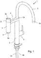
- the water outlet fitting 1 shown comprises a fitting body 2 which is screwed onto a worktop or a kitchen sink.
- the water outlet 3 serves as an outlet for service water.
- service water is understood to mean hot water, cold water or mixed water, as it is obtained from the public water supply or an in-house water supply, but which has no or questionable drinking water quality.
- the water outlet fitting 1 has two supply lines 4a, 4b for hot water and cold water as well as a single lever mixer 5 with a corresponding valve insert, with which the hot and cold water supplied can be mixed and output via the water outlet 3.
- a single lever mixer 5 with a corresponding valve insert, with which the hot and cold water supplied can be mixed and output via the water outlet 3.
- water paths therefore lead in a manner which is also known per se from the supply lines 4a, 4b to the mixing valve 5 and from there to the water outlet 3.
- a second outlet line 6 at the end of which a filter housing 7 pointing vertically downwards is arranged.
- the outlet line 6 is designed in the form of an annular shoulder 6a which lies concentrically around the upwardly pointing outlet line 3 and is pivotable about the central axis of the fitting body 2.
- a waterway for cold water runs on the inside of the fitting body 2 to the shoulder 6a and opens into an annular space formed inside the shoulder 6a, circumferentially open and sealed against the shoulder 6a, via which the water enters the second outlet 6.
- a separate, third water inlet connection (not shown) on the underside of the fitting body 2, which corresponds to the outlet 6 via a waterway within the fitting body 2.
- a third inlet connection is useful, for example, if the drinking water output via the water filter is to be precooled beforehand in a cooler installed under the worktop. If, in this case, the fitting is installed without a cooler, the inlet connection for cold water and the third inlet connection corresponding to the filter outlet can simply be connected to the inlet line for cold water below a worktop via a separate T-piece.
- the filter housing 7 is approximately cylindrical and converges conically towards its bottom 8. In the middle of this conical bottom area 8 there is an orifice 8a from which filtered drinking water can be dispensed.
- a valve 9 with a rotary handle 9a is arranged in the upper region of the filter housing 7. If this valve 9 is opened, water flows via the outlet line 6 into an outer ring area 7a of the filter housing 7, penetrates through the drinking water filter inserted in the filter housing 7 and is discharged axially via the mouth 8a.
- FIG 2 the filter housing 7 is shown enlarged in a longitudinal section.
- the closing valve 9 can be seen with its valve handle 9a and a valve insert 9b located below it.
- a spindle of the valve insert 9b is actuated and the valve 9 releases the water path coming from the outlet line 6 into the valve housing 7.
- valve 10 Between the valve insert 9b and the valve housing 7 there is also a check valve 10 with a closing body 10a, which is held in its open position by a confirmation pin 11 upwards.
- the confirmation pin 11 in turn is held upward by a filter cartridge 12 inserted into the filter housing 7, so that the check valve 10 is open when the filter cartridge 12 is inserted and the filter housing 7 is screwed on.
- a downwardly facing receiving base 6b for the filter housing 7 is formed, on which the latter is fastened in a watertight manner by means of a screw or bayonet lock.
- the valve body 10a is moved downward into its closed position by the water pressure or alternatively a closing spring (not shown here) so that no water can escape from the outlet 6.
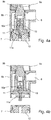
- the open and closed positions of the check valve when the valve cartridge is inserted or removed are in the Figures 4a and 4b shown enlarged again.
- water flows from the outlet line 6 with the valve 9 open and the filter cartridge 12 inserted into an outer annular space 7a of the filter housing 7. From there it flows through the filter material of the filter cartridge 12 and enters an axial cavity 12a of the filter cartridge. From there it flows out of the outlet of the fitting via the mouth opening 8a in the bottom 8 of the filter housing 7, for example into a drinking vessel placed underneath by a user.
- a battery-operated electrical circuit 13 is integrated into the valve cap 9a, which provides information about the state of the filter insert 12 via a multicolored light-emitting diode 14.
- the circuit 13 only contains a timer which is reset after the filter cartridge 12 has been replaced and which reminds the filter cartridge 12 to replace it after a preset operating time has elapsed.
- a flow meter arranged in the waterway, for example in the form of an impeller meter, so that an exchange of the filter cartridge 12 can be indicated depending on the amount of filtered water.
- the light-emitting diode 14 flashes green (for example every 5 seconds). After the intended period of use has expired, i.e. when an exchange of the filter cartridge 12 is recommended, the color of the light-emitting diode 14 changes to red. If the filter cartridge needs to be replaced and the drinking quality of the filter water is no longer guaranteed, a warning is displayed the flashing frequency is also increased, e.g. rapid flashing once per second.
- FIG. 5 A second embodiment of the filter outlet with its filter housing 7 is shown in Figure 5 shown. Identical and identically acting parts are provided with the same reference numerals as in the first exemplary embodiment.
- the filter cartridge 12 has at the lower end a collar 15 which is located around the axial cavity 12a and which serves as a mouthpiece.
- the collar 15 is dimensioned in such a way that it fits into the mouth opening 8 a, which in this case is made larger, in the base 8 of the filter housing 7.
- a so-called jet regulator 16 or aerator is arranged in the interior of the collar 15. This ensures that water from the interior of the filter cartridge 12 is shaped into a water jet and mixed with air bubbles.
- aerator 16 and mouth opening with the surrounding collar or mouth piece 15 are molded directly onto the filter cartridge 12 in one piece, any contact of water with the filter housing 7 or other line or fitting parts after filtering is excluded in this case.
- the filter cartridge 12 and the integrated aerator 16 are designed as disposable parts and are exchanged for hygienic reasons after an intended operating time. This means that the filtered water dispensed by the faucet is always hygienic.
- a filter cartridge 12 is exemplified in Figure 6 shown. It comprises a skeletonized, two-part injection-molded housing 17a, 17b, in which the outer surface is left open over a large area as a filter-active surface. The housing parts 17a, 17b are snapped or latched together at the bottom.
- the outer surface of the cylindrical filter insert 12 is provided with a membrane 18 provided with nano-openings (nanopores).
- nano-openings nanopores
- Such a “nanomembrane” is for example in the document WO 2012/097967 A1 which are hereby fully incorporated by reference to avoid unnecessary repetition.
- the nano-openings in the membrane ensure sufficient water penetration. However, microparticles contained in the water, such as microbiological impurities, are retained.
- the filter cartridge also includes a filter fleece that is too positioned as a pre-filter for suspended matter, an activated carbon layer on the inside and preferably another layer with biologically active silver particles.
- This combination ensures a microbiologically perfect, sterile filtering of drinking water.
- the upper end face of the cylindrical filter insert 12 is closed in a watertight manner. As already explained, it serves to hold the check valve 10 in the open position via the confirmation pin 11.
- the filter insert 12 also has an annular seal 19, which lies around the mouthpiece 15 and which seals the filter cartridge 12 against the bottom 8 of the filter housing 7.
Landscapes
- Engineering & Computer Science (AREA)
- Water Supply & Treatment (AREA)
- Life Sciences & Earth Sciences (AREA)
- Hydrology & Water Resources (AREA)
- Chemical & Material Sciences (AREA)
- Public Health (AREA)
- Health & Medical Sciences (AREA)
- Environmental & Geological Engineering (AREA)
- Organic Chemistry (AREA)
- Chemical Kinetics & Catalysis (AREA)
- Water Treatment By Sorption (AREA)
- Domestic Plumbing Installations (AREA)
- Separation Using Semi-Permeable Membranes (AREA)
Description
- Die vorliegende Erfindung betrifft eine multifunktionale Wasserauslaufarmatur zur wahlweisen Abgabe von Brauchwasser und gefiltertem Trinkwasser, welche einen Armaturenkörper mit mindestens einem Wasserzulauf, einen von dem Armaturenkörper abweisenden ersten Auslauf für Brauchwasser, einen von dem Armaturenkörper abzweigenden zweiten Auslauf für gefiltertes Trinkwasser und einen von Wasser durchströmbaren Filteraufnahmeraum für einen Trinkwasserfilter aufweist, der mit dem zweiten Auslauf in wasserführender Verbindung steht.
- In vielen Gegenden entspricht die Qualität des Wassers aus der öffentlichen Wasserversorgung oder aus einer hauseigenen Wasserversorgung nicht den Hygieneanforderungen an Trinkwasser. In diesem Fall können Trinkwasserfilter eingesetzt werden, um im Brauchwasser enthaltene Verunreinigungen herauszufiltern. Bekannt sind zu diesem Zweck nachrüstbare Filteraufsätze, die auf die Mündungsöffnung des Wasserauslaufs einer Armatur aufgeschraubt oder aufgesteckt werden und einen entsprechenden Trinkwasserfilter enthalten. Derartige nachrüstbaren Filteraufsätze sind beispielsweise in den Dokumenten
EP 0 798 424 A2 ,JP 2002/310357 A JP 2002/331298 A WO 1999/037375 A1 oderWO 1999/029391 A1 beschrieben. Solche auf den Auslauf einer Armatur aufgesetzte Anbaufilter sind jedoch sperrig und dadurch unpraktisch und sind bei normalem Gebrauch der Armatur im Wege wie z.B. bei der Entnahme von Brauchwasser zum Abspülen oder Händewaschen. - Daneben sind Armaturen bekannt, die einen integrierten Trinkwasserfilter aufweisen. Beispielsweise zeigt die
EP 2 249 942 B1 eine Armatur mit im Armaturenkörper integriertem Filter. Die SchriftUS 2014/0215709 A1 beschreibt eine Armatur mit einem separaten Abgang am Armaturenkörper, auf den eine nach oben weisende Filterkartusche aufgesetzt werden kann, an der ein separater Auslauf für gefiltertes Wasser angebracht wird. Über diese Armatur kann somit wahlweise Brauchwasser und gefiltertes Trinkwasser entnommen werden. - Die in der
WO 2013/044339 A1 beschriebene Armatur besitzt ebenfalls einen im Armaturenkorpus aufgenommenen Filter. Am Armaturenkorpus sind zwei Ausläufe angeordnet, aus denen wahlweise Brauchwasser und gefiltertes Trinkwasser entnommen werden kann. Auch dieWO 2012/029412 A1 zeigt schematisch eine Armatur mit einem Auslauf für Brauchwasser, einen Filter sowie einen von dem Filter abgehenden separaten Auslauf für gefiltertes Wasser. - Nachteilig an solchen Armaturen mit integriertem Trinkwasserfilter ist, dass hinter dem Filter jeweils wasserführende Teile der Armatur wie insbesondere Ventile, ein rohrförmiger Auslauf, oder im Armaturenkörper ausgebildete Wasserwege folgen, in denen sich Keime ansiedeln können, die das gefilterte Wasser verunreinigen. Eine solche Keimbildung innerhalb der Armatur kann insbesondere in warmen Gegenden problematisch sein. Gefiltertes Trinkwasser könnte daher hinter dem Filter unbemerkt mit Krankheitskeimen kontaminiert werden.
- Die Schrift
FR 633 782 A - Die Schrift
US 5 753 118 A zeigt eine Armatur mit einem Auslauf für Brauchwasser, der mit einem Einhebelmischer versehen ist, sowie eine zu einem Filtergehäuse führenden Abzweig, der mit einem separaten Schließventil versehen ist. Das Filterwasser wird über einen von dem Filter wegführenden, eigenen Auslauf ausgegeben. - In der
US 4 504 389 A beschreibt ein Filtersystem, welches auf einen Wasserauslauf aufgeschraubt wird. - Es ist daher eine Aufgabe der vorliegenden Erfindung, eine Wasserauslaufarmatur zur wahlweisen Abgabe von Brauchwasser und gefiltertem Trinkwasser anzugeben, welche einerseits im Hinblick auf die Bedienbarkeit, andererseits im Hinblick auf die Hygiene und Sicherheit, verbessert ist.
- Die Aufgabe wird gelöst durch die Merkmale des Anspruchs 1. Vorteilhafte Ausgestaltungen sind den abhängigen Ansprüchen zu entnehmen.
- Bei einer Wasserauslaufarmatur der eingangs genannten Art ist erfindungsgemäß vorgesehen, dass der Filteraufnahmeraum von einem Filtergehäuse gebildet wird, das an dem von dem Armaturenkörper abgewandten Ende des zweiten Auslaufs angeordnet ist, und das Filtergehäuse einen nach unten weisenden Boden aufweist, in welchem eine Mündungsöffnung ausgebildet ist, aus der gefiltertes Trinkwasser entnehmbar ist. Gemäß der vorliegenden Erfindung ist somit vorgesehen, dass das gefilterte Trinkwasser direkt aus dem Filtergehäuse ausfließt und entnommen wird, so dass jede Keimbildung in einem daran anschließenden Wasserweg vermieden wird.
- Am Armaturenkörper ist herkömmlicher Weise ein Ventileinsatz mit einem ersten Ventil zur Regelung eines Wasserflusses von Brauchwasser aus dem ersten Auslauf vorgesehen. Der Armaturenkörper weist hierbei einen ersten Wasserweg von dem ersten Ventil zu dem ersten Auslauf auf.
- Außerdem ist zwischen dem zweiten Auslauf und dem Filtergehäuse ein Schließventil zum Absperren und Freigeben einer Ausgabe von gefiltertem Wasser angeordnet. Erfindungsgemäß weist der Armaturenkörper hierzu einen zweiten Wasserweg von dem Wasserzulauf unter Umgehung des ersten Ventils zu dem zweiten Auslauf auf.
- Somit kann am Armaturenkörper in herkömmlicher Weise das Brauchwasser an- und abgedreht werden. Trinkwasser wird dagegen direkt am Filtergehäuse abgezapft, welches zu diesem Zweck mit dem genannten Schließventil versehen ist. Am Armaturenkörper müssen somit keine zwei separaten Schließventile für Brauchwasser und gefiltertes Trinkwasser oder ein entsprechender Umsteller vorgesehen sein, was die Bedienung der Armatur erleichtert. Das Schließventil am Filtergehäuse ist somit auch eindeutig der Funktion zur Ausgabe von gefiltertem Trinkwasser zugeordnet, was die Armatur intuitiv leicht bedienbar macht.
- Ein solches Schließventil kann insbesondere direkt am Filtergehäuse in dessen oberen, zulaufseitigen Bereich angeordnet sein. Das Filtergehäuse oder ein für das Filtergehäuse vorgesehener Befestigungssockel am zweiten Auslauf bietet genügend Platz, um neben einer Filterpatrone außerdem eine entsprechende Ventilkartusche aufzunehmen.
- Außerdem ist zwischen dem zweiten Auslauf und dem Filtergehäuse ein Rückschlagventil mit einem Absperrelement angeordnet, welches durch eine in das Filtergehäuse eingesetzte Filterpatrone in einer Öffnungsstellung gehalten wird, in der ein Wasserweg von dem zweiten Auslauf in das Filtergehäuse freigegeben ist, und welches bei Fehlen einer Filterpatrone unter Wirkung einer Schließfeder oder des Wasserdrucks in eine Schließstellung bewegt wird, in der es den Wasserweg zwischen zweitem Auslauf und Filtergehäuse versperrt. Ein solches Rückschlagventil verhindert einerseits, dass beim Öffnen des Filtergehäuses, beispielsweise zwecks Austausch der Filterpatrone, Wasser ausströmen kann. Außerdem verhindert das Rückschlagventil, dass bei Fehlen einer Filterpatrone Wasser entnommen werden kann. Die Ausgabefunktion für gefiltertes Trinkwasser ist somit blockiert, solange keine Filterpatrone eingesetzt ist, sodass ein Benutzer nicht versehentlich im Vertrauen darauf, es sei eine Filterpatrone vorhanden, ungefiltertes Wasser als Trinkwasser entnehmen könnte.
- Bei einer bevorzugten Ausführungsform ist vorgesehen, dass das Filtergehäuse als ein vorzugsweise zylinderförmiges Gehäuse mit gegenüber dem zweiten Auslauf vergrößerten Querschnitt ausgebildet ist, in dessen oberen Bereich der zweite Auslauf einmündet. Das Filtergehäuse wird somit im Wesentlichen in vertikaler Richtung durchströmt und bietet ausreichend Platz zur Aufnahme einer Filterpatrone.
- Vorzugsweise ist das Filtergehäuse zylindrisch ausgebildet, derart, dass Wasser von dem zweiten Auslauf in einen äußeren Ring umströmt, eine in das Filtergehäuse eingesetzte zylindrische Filterpatrone durchdringt und in axialer Richtung mittig aus der im Boden des Filtergehäuses ausgebildeten Mündungsöffnung austritt. Die radialsymmetrische, insbesondere zylindrische Form von Filterpatrone und Filtergehäuse ist bevorzugt, da hierbei die Filterpatrone von außen angeströmt und das gefilterte Wasser direkt aus dem axialen Innenraum des Filters entnommen werden kann. Die komplette Außenseite der Filterpatrone, die beispielsweise beim Einsetzen angefasst wird und somit Kontaminationen ausgesetzt ist, stellt somit die "unreine" Seite des Filters dar, während die reine Seite des Filters im Inneren der Filterpatrone vor Umwelteinflüssen und Kontamination geschützt ist.
- Das Filtergehäuse kann zum Austausch und zum Einsetzen einer Filterpatrone geöffnet oder abgenommen werden. Vorzugsweise kann hierzu das Filtergehäuse mit einem Schlauch- oder Bajonettverschluss versehen sein, mit dem es an einem nach unten weisenden Aufnahmesockel am vom Armaturenkörper entfernten Ende des zweiten Auslaufs gehalten ist. Dies ermöglicht einen einfachen und benutzerfreundlichen Austausch des Trinkwasserfilters.
- Zur Verbesserung der Bedienbarkeit und Flexibilität der Armatur kann vorzugsweise vorgesehen sein, dass der zweite Auslauf gegenüber dem Armaturenkörper schwenkbar ist. Er kann somit in eine Position geschwenkt werden, in der er, beispielsweise beim Abwasch oder anderweitigen Gebrauch der Armatur, dem ersten Auslauf für Brauchwasser nicht im Wege ist.
- Der zweite Auslauf kann insbesondere über eine konzentrisch um den ersten Auslauf ausgebildete, ringförmige Schulter mit dem Armaturenkörper drehbar verbunden sein.
- Der Ventileinsatz am Armaturenkörper kann insbesondere als Mischventil ausgebildet sein. Die Armatur weist somit einen Warmwasser- und einen Kaltwasserzulauf auf, die zu dem Mischventil führen. Der erste Wasserweg führt somit vom Mischventil kommendes Mischwasser. Der zweite Wasserweg zweigt dagegen direkt von dem Kaltwasserzulauf ab und führt Kaltwasser. Alternativ ist es auch möglich, die Armatur mit einem dritten Wasserzulauf auszubilden, über den Wasser, beispielsweise von einer unter der Arbeitsplatte angeordneten Kühlvorrichtung zugeführt und über den zweiten Auslauf als gekühltes und gefiltertes Wasser ausgegeben wird.
- Bei einer weiteren Ausführungsform der Erfindung ist in dem Filtergehäuse eine elektronische Zählervorrichtung integriert und bei dem Filtergehäuse eine mit der Zählervorrichtung verbundene optische Anzeige angeordnet, welche einen Funktionszustand einer in das Filtergehäuse eingesetzten Filterpatrone anzeigt. Da der Filtereinsatz üblicherweise nach einer bestimmten Gebrauchsdauer erschöpft bzw. unbrauchbar wird, kann somit sichergestellt werden, dass rechtzeitig dem Benutzer angezeigt wird, dass ein neuer Filtereinsatz eingesetzt werden soll. Die Zählervorrichtung kann insbesondere einen Durchflussmesser umfassen, sodass in Abhängigkeit der Menge des gezapften gefilterten Trinkwassers ein Austausch der Filterpatrone angezeigt werden kann. Alternativ kann auch lediglich ein Timer vorgesehen sein, der jeweils nach Anlauf einer vorgegebenen Zeitspanne einen Filteraustausch signalisiert.
- Als besonders bevorzugte Maßnahme ist im Rahmen der vorliegenden Erfindung vorgesehen, dass die Mündungsöffnung am Boden des Filtergehäuses ein an der Filterpatrone angeordnetes Mündungsstück aufnimmt, aus welchem gefiltertes Wasser aus der Filterpatrone austritt. Indem das Wasser aus einem an der Filterpatrone angeordnetem Mündungsstück austritt, ist jeder Kontakt des gefilterten Wassers auf der "reinen" Seite der Filterpatrone mit jedweden Teilen der Armatur ausgeschlossen, sodass eine Rekontamination des gefilterten Wassers hinter der Filterpatrone unmöglich ist.
- Das an der Filterpatrone angeordnete Mündungsstück kann im Auslieferungszustand mittels einer Abreißfolie steril versiegelt sein. Diese wird erst entfernt, wenn die Filterpatrone in das Filtergehäuse eingesetzt wird. Somit ist der hygienisch einwandfreie Zustand der Filterpatrone gewährleistet.
- Bevorzugt ist außerdem, wenn das Mündungsstück zusätzlich einen integrierten Strahlregler umfasst. Ein solcher Strahlregler ist üblicherweise am Auslauf einer Armatur angeordnet und sorgt dafür, dass das Wasser mit der gewünschten Strahlcharakteristik, gegebenenfalls belüftet, aus dem Auslauf austritt. Ein solcher Strahlregler ist konstruktionsbedingt besonders anfällig für die Anlagerung von Verschmutzungen und kann eine Quelle von Keimbildung innerhalb der Armatur darstellen. Indem dieser Strahlregler nun integriert mit der Filterkartusche als Einwegartikel ausgebildet ist, entfällt dieser als Quelle für Keimbildung, ohne auf die mit einem Strahlregler verbundene Komfortfunktion verzichten zu müssen.
- Weitere Vorteile und Ausgestaltungen der vorliegenden Erfindung ergeben sich aus der nachfolgenden Beschreibung bevorzugter Ausführungsbeispiele anhand der Figuren. Diese zeigen:
- Figur 1
- eine isometrische Darstellung einer Wasserauslaufarmatur mit separaten Auslässen für Brauchwasser und gefiltertes Trinkwasser,
- Figur 2
- einen Schnitt durch Filtergehäuse und Auslass für gefiltertes Wasser der Armatur aus
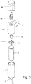
Figur 1 , - Figur 3
- eine Explosionszeichnung des Filtergehäuses aus
Figur 2 , - Figur 4a
- einen Schnitt im Detail durch ein im Filtergehäuse vorhandenes Rückschlagventil,
- Figur 4b
- das Rückschlagventil aus
Figur 4a bei abgenommener Filterpatrone - Figur 5
- ein Schnitt durch Filtergehäuse und Filterauslass in einem zweiten Ausführungsbeispiel und
- Figur 6
- eine isometrische Darstellung einer im dem zweiten Ausführungsbeispiel verwendbaren Filterpatrone.
- Die in
Figur 1 gezeigte Wasserauslaufarmatur 1 umfasst einen Armaturenkörper 2, der auf einer Arbeitsplatte oder einer Küchenspüle verschraubt wird. Nach oben hin erstreckt sich aus dem Armaturenkörper 2 ein gebogener Wasserauflauf 3 mit einem Mündungsstück 3a herkömmlicher Bauart, beispielsweise einem Strahlregler. Der Wasserauslauf 3 dient als Auslauf für Brauchwasser. Als Brauchwasser wird im Rahmen der Erfindung Warmwasser, Kaltwasser oder Mischwasser verstanden, wie es aus der öffentlichen Wasserversorgung oder einer hauseigenen Wasserversorgung bezogen wird, welches aber keine bzw. fragliche Trinkwasserqualität aufweist. - Die Wasserauslaufarmatur 1 hat zwei Zuleitungen 4a, 4b für Warmwasser und Kaltwasser sowie einen Ein-Hebel-Mischer 5 mit entsprechendem Ventileinsatz, mit dem das zugeführte Warm- und Kaltwasser gemischt und über den Wasserauslauf 3 ausgegeben werden kann. Innerhalb des Armaturenkörpers 2 führen somit in an sich ebenfalls bekannter Weise Wasserwege von den Zuleitungen 4a, 4b zum Mischventil 5 und von dort zum Wasserauslauf 3.
- Im oberen Bereich des Armaturenkörpers 2 zweigt (in diesem Fall in etwa waagerecht, ohne dass die Erfindung jedoch hierauf beschränkt wäre) eine zweite Auslaufleitung 6 ab, an deren Ende ein senkrecht nach unten weisendes Filtergehäuse 7 angeordnet ist. Im Bereich der Abzweigung ist die Auslaufleitung 6 in Form einer ringförmigen Schulter 6a ausgebildet, die konzentrisch um die nach oben weisende Auslaufleitung 3 liegt und um die Mittelachse des Armaturenkörpers 2 schwenkbar ist. Ein Wasserweg für Kaltwasser verläuft innenseitig des Armaturenkörpers 2 zu der Schulter 6a und mündet dort in einem innerhalb der Schulter 6a ausgebildeten, umfangseitig offenen und gegenüber der Schulter 6a gleitend gedichteten Ringraum, über den das Wasser in den zweiten Auslauf 6 gelangt.
- Ebenso wäre es möglich, einen separaten, dritten Wasserzulaufanschluss (nicht gezeigt) an der Unterseite des Armaturenkörpers 2 vorzusehen, der über einen Wasserweg innerhalb des Armaturenkörpers 2 mit dem Auslauf 6 korrespondiert. Ein solcher dritter Zulaufanschluss ist beispielsweise sinnvoll, wenn das über den Wasserfilter ausgegebene Trinkwasser zuvor in einem unter der Arbeitsplatte installierten Kühler vorgekühlt werden soll. Wenn in diesem Falle die Armatur ohne Kühler installiert wird, können der Zulaufanschluss für Kaltwasser und der mit dem Filterausgang korrespondierende dritte Zulaufanschluss einfach unterhalb einer Arbeitsplatte über ein separates T-Stück mit der Zulaufleitung für Kaltwasser verbunden werden.
- Das Filtergehäuse 7 ist in etwa zylindrisch ausgebildet und läuft zu seinem Boden 8 hin kegelförmig zusammen. In der Mitte dieses kegelförmigen Bodenbereichs 8 befindet sich eine Mündungsöffnung 8a, aus der gefiltertes Trinkwasser ausgegeben werden kann. Hierzu ist im oberen Bereich des Filtergehäuses 7 ein Ventil 9 mit einem Drehgriff 9a angeordnet. Wird dieses Ventil 9 geöffnet, so strömt Wasser über die Auslaufleitung 6 in einen äußeren Ringbereich 7a des Filtergehäuses 7, dringt durch den im Filtergehäuse 7 eingesetzten Trinkwasserfilter hindurch und wird axial über die Mündungsöffnung 8a ausgegeben.
- In
Figur 2 ist das Filtergehäuse 7 vergrößert in einem Längsschnitt dargestellt. Im oberen Bereich ist das Schließventil 9 mit seinem Ventilgriff 9a und einem darunter befindlichen Ventileinsatz 9b zu sehen. Durch Drehen des Ventilgriffs 9a wird eine Spindel des Ventileinsatzes 9b betätigt und das Ventil 9 gibt den Wasserweg von der Auslaufleitung 6 kommend ins Ventilgehäuse 7 frei. - Zwischen dem Ventileinsatz 9b und dem Ventilgehäuse 7 befindet sich außerdem ein Rückschlagventil 10 mit einem Schließkörper 10a, der von einem Bestätigungsstift 11 nach oben in seiner geöffneten Stellung gehalten wird. Der Bestätigungsstift 11 wiederum wird von einer in das Filtergehäuse 7 eingesetzten Filterpatrone 12 nach oben gehalten, sodass das Rückschlagventil 10 bei eingesetzter Filterpatrone 12 und aufgeschraubtem Filtergehäuse 7 geöffnet ist.
- Am Ende der Wasserauslaufleitung 6 ist ein nach unten weisender Aufnahmesockel 6b für das Filtergehäuse 7 angeformt, an dem dieses mittels eines Schraub- oder Bajonett-Verschlusses wasserdicht befestigt ist. Wird das Filtergehäuse 7 abgenommen, um den Filtereinsatz 12 zu wechseln, so wird durch den Wasserdruck oder alternativ eine (hier nicht gezeigte) Schließfeder der Ventilkörper 10a nach unten in seine Schließstellung bewegt, sodass kein Wasser aus dem Auslauf 6 austreten kann. Öffnungsstellung und Schließstellung des Rückschlagventils bei eingesetzter bzw. abgenommener Ventilpatrone sind in den
Figuren 4a und 4b nochmals vergrößert dargestellt. Man erkennt in Figur 4b insbesondere den in Richtung seines unteren Anschlags bewegten Bestätigungsstift 11 mit einer Bestätigungsscheibe 11a, welche in eine korrespondierende Ausnehmung 12a im oberen Bereich der Filterpatrone 12 in Eingriff gelangt und von dieser nach oben gehalten wird, wenn die Filterpatrone 12, wie inFigur 4a gezeigt, eingesetzt und mittels des Filtergehäuses 7 aufgeschraubt wird. - Im Betrieb fließt Wasser aus der Auslaufleitung 6 bei geöffnetem Ventil 9 und eingesetzter Filterpatrone 12 in einen äußeren Ringraum 7a des Filtergehäuses 7. Von dort durchströmt es das Filtermaterial der eingesetzten Filterpatrone 12 und gelangt in einen axialen Hohlraum 12a der Filterpatrone. Von dort fließt es über die Mündungsöffnung 8a im Boden 8 des Filtergehäuses 7 aus dem Auslass der Armatur heraus, beispielsweise in ein von einem Benutzer darunter platziertes Trinkgefäß.
- Als eine zusätzliche (optionale) Funktion ist in die Ventilkappe 9a eine batteriebetriebene elektrische Schaltung 13 integriert, die über eine mehrfarbige Leuchtdiode 14 Auskunft über den Zustand des Filtereinsatzes 12 gibt. Im Ausführungsbeispiel enthält die Schaltung 13 lediglich einen Timer, der nach Austausch der Filterpatrone 12 zurückgesetzt wird und nach Ablauf einer voreingestellten Betriebszeit für die Filterpatrone 12 an einen Austausch erinnert. Möglich ist jedoch alternativ oder kumulativ auch die Verwendung eines im Wasserweg angeordneten Durchflussmessers, beispielsweise in Form eines Flügelradzählers, so dass ein Austausch der Filterpatrone 12 in Abhängigkeit der gefilterten Wassermenge angezeigt werden kann. Solange die Filterpatrone 12 in innerhalb ihrer vorgesehenen Verwendungsdauer ist, blinkt die Leuchtdiode 14 grün (z.B. alle 5 sec). Nach Ablauf der vorgesehenen Verwendungsdauer, wenn also ein Austausch der Filterpatrone 12 empfohlen wird, wechselt die Farbe der Leuchtdiode 14 auf rot. Ist ein Austausch der Filterpatrone überfällt und die Trinkqualität des Filterwassers somit nicht mehr gewährleistet, so wird als Warnung zusätzlich die Blinkfrequenz erhöht, z.B. schnelles Blinken 1x pro Sekunde.
- Ein zweites Ausführungsbeispiel des Filterauslaufs mit seinem Filtergehäuse 7 ist in
Figur 5 gezeigt. Gleiche und gleichwirkende Teile sind hierbei mit gleichen Bezugszeichen wie im ersten Ausführungsbeispiel versehen. Die Filterpatrone 12 weist im zweiten Ausführungsbeispiel am unteren Ende einen um den axialen Hohlraum 12a liegenden Kragen 15 auf, der als Mündungsstück dient. Der Kragen 15 ist so bemessen, dass er in die in diesem Fall größer ausgeführte Mündungsöffnung 8a im Boden 8 des Filtergehäuses 7 hindurch passt. Im Inneren des Kragens 15 ist ein sogenannter Strahlregler 16 oder Luftsprudler angeordnet. Dieser sorgt dafür, dass Wasser aus dem Inneren der Filterpatrone 12 zu einem Wasserstrahl geformt und mit Luftblasen vermischt austritt. Indem Luftsprudler 16 und Mündungssöffnung mit dem diese umgebenden Kragen bzw. Mündungsstück 15 direkt einstückig an die Filterpatrone 12 angeformt sind, ist in diesem Fall jeder Kontakt von Wasser mit dem Filtergehäuse 7 oder anderen Leitungs- oder Armaturenteilen nach der Filterung ausgeschlossen. Filterpatrone 12 und der integrierte Luftsprudler 16 sind als Einwegteil ausgelegt und werden nach einer vorgesehenen Betriebsdauer aus hygienischen Gründen ausgetauscht. Somit ist das von der Armatur ausgegebene gefilterte Wasser stets hygienisch einwandfrei. - Eine Filterpatrone 12 ist beispielhaft in
Figur 6 dargestellt. Sie umfasst ein skelettiertes, zweiteiliges Spritzgussgehäuse17a, 17b, bei dem die Mantelfläche als filteraktive Fläche großflächig ausgespart ist. Die Gehäuseteile 17a, 17b sind bodenseitig miteinander verschnappt bzw. verrastet. Die Mantelfläche des zylindrischen Filtereinsatzes 12 ist mit einer mit Nanoöffnungen (Nanoporen) versehenen Membran 18 versehen. Eine solche "Nanomembran" ist beispielsweise in der SchriftWO 2012/097967 A1 beschrieben, auf die zur Vermeidung unnötiger Wiederholungen hiermit vollinhaltlich Bezug genommen wird. Die Nanoöffnungen in der Membran sorgen für einen ausreichenden Wasserdurchtritt. Im Wasser enthaltene Mikropartikel wie etwa mikrobiologische Verunreinigungen werden jedoch zurückgehalten. - Außer der Nanomembran umfasst die Filterpatrone zusätzlich ein zu äußerst liegendes Filtervlies als Vorfilter für Schwebstoffe, eine innenliegende Aktivkohleschicht sowie vorzugsweise noch eine weitere Lage mit biologisch aktiven Silberpartikeln. Diese Kombination sorgt für eine mikrobiologisch einwandfreie, sterile Filterung von Trinkwasser. Die obere Stirnfläche des zylindrischen Filtereinsatzes 12 ist wasserdicht verschlossen. Sie dient wie bereits erläutert dazu, über den Bestätigungsstift 11 das Rückschlagventil 10 in Offenstellung zu halten. An der Unterseite besitzt der Filtereinsatz 12 außerdem eine ringförmige, um das Mündungsstück 15 liegende Dichtung 19, welche die Filterpatrone 12 gegen den Boden 8 des Filtergehäuses 7 abdichtet. Somit kann in das Filtergehäuse 7 aus der Auslaufleitung 6 eingeströmtes Wasser lediglich nach Durchdringen der filteraktiven Schichten in den axialen Innenraum 12a der Filterpatrone 12 gelangen und von dort aus durch das an der Filterpatrone angebrachte Mündungsstück 15 ausfließen.
Claims (13)
- Multifunktionale Wasserauslaufarmatur (1) zur wahlweisen Abgabe von Brauchwasser und gefiltertem Trinkwasser, welche einen Armaturenkörper (2) mit mindestens einem Wasserzulauf (4a, 4b), einen von dem Armaturenkörper (2) abweisenden ersten Auslauf (3) für Brauchwasser, einen von dem Armaturenkörper (2) abzweigenden zweiten Auslauf (6) für gefiltertes Trinkwasser und einen von Wasser durchströmbaren Filteraufnahmeraum für eine als Trinkwasserfilter dienende Filterpatrone (12) aufweist, der mit dem zweiten Auslauf (6) in wasserführender Verbindung steht, wobei am Armaturenkörper (2) ein Ventileinsatz (5) mit einem Ventil zur Regelung eines Wasserflusses von Brauchwasser aus dem ersten Auslauf (3) vorgesehen ist und der Armaturenkörper (2) einen ersten Wasserweg von dem Ventil (5) zu dem ersten Auslauf (3) aufweist, wobeider Filteraufnahmeraum von einem Filtergehäuse (7) gebildet wird, das an dem von dem Armaturenkörper (2) abgewandten Ende des zweiten Auslaufs (6) angeordnet ist, und das Filtergehäuse (7) einen nach unten weisenden Boden (8) aufweist, in welchem eine Mündungsöffnung (8a) ausgebildet ist, aus der gefiltertes Trinkwasser entnehmbar ist,der Armaturenkörper (2) einen zweiten Wasserweg von dem Wasserzulauf (4a) unter Umgehung des Ventils (5) zu dem zweiten Auslauf (6) aufweist, und wobeizwischen dem zweiten Auslauf (6) und dem Filtergehäuse (7) ein Schließventil (9) zum Absperren und Freigeben einer Ausgabe von gefiltertem Wasser angeordnet ist,dadurch gekennzeichnet, dass
zwischen dem zweiten Auslauf (6) und dem Filtergehäuse (7) ein Rückschlagventil (10) mit einem Absperrelement (10a) angeordnet ist, welches durch eine in das Filtergehäuse (7) eingesetzte Filterpatrone (12) in einer Öffnungsstellung gehalten wird, in der ein Wasserweg von dem zweiten Auslauf (6) in das Filtergehäuse (7) freigegeben ist, und welches bei Fehlen einer Filterpatrone (12) unter Wirkung einer Schließfeder oder des Wasserdrucks in eine Schließstellung bewegt wird, in der es den Wasserweg zwischen zweitem Auslauf (6) und Filtergehäuse (7) versperrt. - Wasserauslaufarmatur nach Anspruch 1, bei der das Filtergehäuse (7) als ein vorzugsweise zylinderförmiges Gehäuse mit gegenüber dem zweiten Auslauf (6) vergrößerten Querschnitt ausgebildet ist, in dessen oberen Bereich der zweite Auslauf (6) einmündet.
- Wasserauslaufarmatur nach einem der vorangehenden Ansprüche, bei der das Filtergehäuse (7) zylindrisch ausgebildet ist, derart, dass Brauchwasser von dem zweiten Auslauf (6) in einen äußeren Ringraum (7a) strömt, eine in das Filtergehäuse (7) eingesetzte zylindrische Filterpatrone (12) durchdringt und in axialer Richtung mittig aus der im Boden (8) des Filtergehäuses (7) ausgebildeten Mündungsöffnung (8a) austritt.
- Wasserauslaufarmatur nach einem der vorangehenden Ansprüche, bei der das Filtergehäuse (7) zum Austausch und zum Einsetzen einer Filterpatrone (12) geöffnet oder abgenommen werden kann.
- Wasserauslaufarmatur nach dem vorangehenden Anspruch, bei der das Filtergehäuse (7) mit einem Schraub- oder Bajonettverschluss versehen ist, mit dem es an einem nach unten weisenden Aufnahmesockel (6b) am vom Armaturenkörper (2) entfernten Ende des zweiten Auslaufs (6) gehalten ist.
- Wasserauslaufarmatur nach einem der vorangehenden Ansprüche, bei der der zweite Auslauf (6) gegenüber dem Armaturenkörper (2) schwenkbar ist.
- Wasserauslaufarmatur nach einem der vorangehenden Ansprüche, bei der der zweite Auslauf (6) über eine konzentrisch um den ersten Auslauf (3) ausgebildete, ringförmige Schulter (6a) mit dem Armaturenkörper (2) drehbar verbunden ist.
- Wasserauslaufarmatur nach einem der vorangehenden Ansprüche, bei der der Ventileinsatz (5) als Mischventil ausgebildet ist, wobei die Wasserauslaufarmatur (1) einen Warmwasser- (4b) und einen Kaltwasserzulauf (4a) aufweist, die zu dem Mischventil (5) führen, wobei der erste Wasserweg von dem Mischventil (5) kommendes Mischwasser führt und der zweite Wasserweg von dem Kaltwasserzulauf (4a) abzweigt und Kaltwasser führt.
- Wasserauslaufarmatur nach einem der vorangehenden Ansprüche, bei der in dem Filtergehäuse (7) eine elektronische Zählervorrichtung (13) integriert und an dem Filtergehäuse (7) eine mit der Zählervorrichtung (13) verbundene optische Anzeige (14) angeordnet ist, welche einen Funktionszustand einer in das Filtergehäuse (7) eingesetzten Filterpatrone (12) anzeigt.
- Wasserauslaufarmatur nach Anspruch 9, bei der die Zählvorrichtung (13) einen Timer und/oder einen Durchflussmesser umfasst.
- Wasserauslaufarmatur nach einem der vorangehenden Ansprüche, bei der die Mündungsöffnung (8a) ein an der Filterpatrone (12) angeordnetes Mündungsstück (15) aufnimmt, aus welchem gefiltertes Wasser aus der Filterpatrone (12) austritt.
- Wasserauslaufarmatur nach Anspruch 11, bei der das an der Filterpatrone (12) angeordnete Mündungsstück (15) im Auslieferungszustand mittels einer Abreißfolie steril versiegelt ist.
- Wasserauslaufarmatur nach Anspruch 11 oder 12, bei der das Mündungsstück (15) einen integrierten Strahlregler (16) enthält.
Applications Claiming Priority (1)
| Application Number | Priority Date | Filing Date | Title |
|---|---|---|---|
| DE102018114581.0A DE102018114581A1 (de) | 2018-06-18 | 2018-06-18 | Wasserauslaufarmatur mit Trinkwasserfilter |
Publications (2)
| Publication Number | Publication Date |
|---|---|
| EP3583993A1 EP3583993A1 (de) | 2019-12-25 |
| EP3583993B1 true EP3583993B1 (de) | 2020-09-30 |
Family
ID=66770226
Family Applications (1)
| Application Number | Title | Priority Date | Filing Date |
|---|---|---|---|
| EP19178198.8A Active EP3583993B1 (de) | 2018-06-18 | 2019-06-04 | Wasserauslaufarmatur mit trinkwasserfilter |
Country Status (5)
| Country | Link |
|---|---|
| US (1) | US20190382986A1 (de) |
| EP (1) | EP3583993B1 (de) |
| CN (1) | CN210531713U (de) |
| DE (1) | DE102018114581A1 (de) |
| ES (1) | ES2828702T3 (de) |
Cited By (1)
| Publication number | Priority date | Publication date | Assignee | Title |
|---|---|---|---|---|
| IT202300020901A1 (it) * | 2023-10-09 | 2025-04-09 | Giorgio Giacomo Castagno | Kit e metodo di aggiornamento di un rubinetto monocomando e rubinetto monocomando smart |
Families Citing this family (2)
| Publication number | Priority date | Publication date | Assignee | Title |
|---|---|---|---|---|
| DE102020212802A1 (de) * | 2020-10-09 | 2022-04-14 | Blanco Gmbh + Co Kg | Armatur zur Ausgabe von Flüssigkeiten und Flüssigkeitsausgabesystem |
| USD1053311S1 (en) * | 2022-06-02 | 2024-12-03 | Be Wtr Sa | Faucet |
Family Cites Families (21)
| Publication number | Priority date | Publication date | Assignee | Title |
|---|---|---|---|---|
| FR633782A (fr) * | 1927-05-03 | 1928-02-03 | Simoneton Ets | Filtre |
| US4504389A (en) * | 1983-01-17 | 1985-03-12 | Associated Mills, Inc. | Water filter |
| US5653868A (en) | 1994-04-06 | 1997-08-05 | Mitsubishi Rayon Company Ltd. | Diverter and water purifier having same |
| DE29505662U1 (de) * | 1995-04-01 | 1995-11-09 | Haarig, Gerhard, 40476 Düsseldorf | Haushaltswasserfilter mit mehreren Gehäuseteilen mit Filterpatrone sowie Erweiterungssätze |
| US5753118A (en) * | 1996-12-16 | 1998-05-19 | Yang; Tsai Chen | Faucet and filter assembly |
| US6096197A (en) | 1997-12-11 | 2000-08-01 | Hughes; Douglass E. | Shower filter for chlorine removal and scale deposit prevention |
| PL348456A1 (en) | 1998-01-21 | 2002-05-20 | Clorox Co | Faucet mounted water filter |
| US6251274B1 (en) * | 1999-03-16 | 2001-06-26 | Envirogard Products Limited | Faucet attachment for treating water |
| DE19950940A1 (de) * | 1999-10-21 | 2001-04-26 | Spiegel Margret | Verfahren um herkömmliche Zapfventile (Mischbatterien Einhand- oder Zweihandhebel) mit einen zweiten Hahnauslauf umzurüsten |
| JP2002310357A (ja) | 2001-04-18 | 2002-10-23 | Toray Ind Inc | 自在継手および浄水器 |
| JP3906344B2 (ja) | 2001-05-09 | 2007-04-18 | 和歌山県 | 排水処理装置および排水処理方法 |
| DE102005011960A1 (de) * | 2005-03-14 | 2006-09-21 | Miličić, Dragan, Dipl.-Ing. | Wasserarmatur |
| BE1019019A3 (nl) | 2008-01-14 | 2012-01-10 | Jonghe Marc De | Een watervoorzieningseenheid voor het afleveren van gezuiverd water. |
| JP2012050904A (ja) | 2010-08-31 | 2012-03-15 | Panasonic Electric Works Co Ltd | 浄水カートリッジ、当該浄水カートリッジを備えた浄水装置および当該浄水装置を備えた流し台 |
| EP2476724A1 (de) | 2011-01-17 | 2012-07-18 | ETH Zurich | Poröse Polymermembrane |
| ITBO20110195A1 (it) * | 2011-04-13 | 2012-10-14 | Crea Srl | Gruppo rubinetto per l'erogazione di un liquido filtrato e di un liquido non filtrato |
| BRPI1104487B1 (pt) | 2011-09-26 | 2020-12-01 | Duratex S.A | torneira misturadora com filtro |
| US9650767B2 (en) | 2013-02-01 | 2017-05-16 | Scott Anthony Nightlinger | Sink faucet assembly |
| US20150068987A1 (en) * | 2013-09-09 | 2015-03-12 | 3M Innovative Properties Company | Filtration systems for faucets |
| DE102014105532B4 (de) * | 2014-04-17 | 2016-12-15 | Grünbeck Wasseraufbereitung GmbH | Wasserauslaufarmatur mit Filter, Anschlussstück zum Anschließen an eine Wasserauslaufarmatur und Verfahren zum Betrieb einer Wasserauslaufarmatur |
| CN104445502A (zh) * | 2014-11-28 | 2015-03-25 | 张家港市大能塑料制品有限公司 | 一种多功能带弯道滤水器 |
-
2018
- 2018-06-18 DE DE102018114581.0A patent/DE102018114581A1/de not_active Ceased
-
2019
- 2019-06-04 EP EP19178198.8A patent/EP3583993B1/de active Active
- 2019-06-04 ES ES19178198T patent/ES2828702T3/es active Active
- 2019-06-12 CN CN201920883706.5U patent/CN210531713U/zh active Active
- 2019-06-17 US US16/442,938 patent/US20190382986A1/en not_active Abandoned
Non-Patent Citations (1)
| Title |
|---|
| None * |
Cited By (1)
| Publication number | Priority date | Publication date | Assignee | Title |
|---|---|---|---|---|
| IT202300020901A1 (it) * | 2023-10-09 | 2025-04-09 | Giorgio Giacomo Castagno | Kit e metodo di aggiornamento di un rubinetto monocomando e rubinetto monocomando smart |
Also Published As
| Publication number | Publication date |
|---|---|
| EP3583993A1 (de) | 2019-12-25 |
| DE102018114581A1 (de) | 2019-12-19 |
| CN210531713U (zh) | 2020-05-15 |
| ES2828702T3 (es) | 2021-05-27 |
| US20190382986A1 (en) | 2019-12-19 |
Similar Documents
| Publication | Publication Date | Title |
|---|---|---|
| DE69624118T2 (de) | Dialysemaschine | |
| DE2640115C2 (de) | Vorrichtung zur Wasserreinigung | |
| EP0018527B1 (de) | Rückspülbare Filtereinrichtung, insbesondere für eine Hauswasseranlage | |
| DE112010003584B4 (de) | Notfall-waschsystem | |
| EP3583992B1 (de) | Filtereinsatz für eine wasserauslaufarmatur mit trinkwasserfilter | |
| EP3766828A2 (de) | Sanitärarmatur zum abgeben von aufbereiteten flüssigkeiten | |
| EP3337931B1 (de) | Vorrichtung und verfahren zum selbsttätigen spülen mit mehrfachventil | |
| DE2607873A1 (de) | Umschaltventil, insbesondere fuer wasseranschluesse | |
| WO1997049875A1 (de) | Wasserauslauf-armatur | |
| EP3583993A1 (de) | Wasserauslaufarmatur mit trinkwasserfilter | |
| EP1789636A1 (de) | Sanitäre auslaufeinheit | |
| EP1576307B1 (de) | Sanitäre auslaufarmatur | |
| EP2708664B1 (de) | Auslaufarmatur umfassend einen als Tischkaraffe ausgebildeten Auslaufkörper | |
| DE102006021838A1 (de) | Mechanisch absperrbare Mischbatterie | |
| DE102009060455A1 (de) | Wasserarmatur mit zwei Zulaufkanälen | |
| DE3633875A1 (de) | Einrichtung zum beruehrungslosen wasserspenden | |
| WO2022089692A1 (de) | Bidetbrause-brausekopf | |
| DE202018001078U1 (de) | Sprühstrahlhahn mit einfachem Einlass und Zerstäuber-Einsatz für diesen Hahn | |
| DE102005040159B3 (de) | Sanitäre Auslaufarmatur, insbesondere Einhebelmischer | |
| DE2007572A1 (de) | Waschtisch mit einem Wasserausfluß | |
| DE2338096C2 (de) | Sanitär-Armatur | |
| DE102020122892A1 (de) | Bidetsystem | |
| DE8327503U1 (de) | Mischhahn fuer waschbecken, bidets oder sitzbecken u.dgl. | |
| DE102007010965B3 (de) | Sanitärarmatur | |
| DE2937474C2 (de) | Überlauf-Mischbatterie |
Legal Events
| Date | Code | Title | Description |
|---|---|---|---|
| PUAI | Public reference made under article 153(3) epc to a published international application that has entered the european phase |
Free format text: ORIGINAL CODE: 0009012 |
|
| STAA | Information on the status of an ep patent application or granted ep patent |
Free format text: STATUS: THE APPLICATION HAS BEEN PUBLISHED |
|
| AK | Designated contracting states |
Kind code of ref document: A1 Designated state(s): AL AT BE BG CH CY CZ DE DK EE ES FI FR GB GR HR HU IE IS IT LI LT LU LV MC MK MT NL NO PL PT RO RS SE SI SK SM TR |
|
| AX | Request for extension of the european patent |
Extension state: BA ME |
|
| STAA | Information on the status of an ep patent application or granted ep patent |
Free format text: STATUS: REQUEST FOR EXAMINATION WAS MADE |
|
| 17P | Request for examination filed |
Effective date: 20200402 |
|
| RBV | Designated contracting states (corrected) |
Designated state(s): AL AT BE BG CH CY CZ DE DK EE ES FI FR GB GR HR HU IE IS IT LI LT LU LV MC MK MT NL NO PL PT RO RS SE SI SK SM TR |
|
| GRAP | Despatch of communication of intention to grant a patent |
Free format text: ORIGINAL CODE: EPIDOSNIGR1 |
|
| RIC1 | Information provided on ipc code assigned before grant |
Ipc: B01D 35/04 20060101AFI20200429BHEP Ipc: E03C 1/04 20060101ALI20200429BHEP Ipc: C02F 1/00 20060101ALI20200429BHEP |
|
| STAA | Information on the status of an ep patent application or granted ep patent |
Free format text: STATUS: GRANT OF PATENT IS INTENDED |
|
| INTG | Intention to grant announced |
Effective date: 20200604 |
|
| GRAS | Grant fee paid |
Free format text: ORIGINAL CODE: EPIDOSNIGR3 |
|
| GRAA | (expected) grant |
Free format text: ORIGINAL CODE: 0009210 |
|
| STAA | Information on the status of an ep patent application or granted ep patent |
Free format text: STATUS: THE PATENT HAS BEEN GRANTED |
|
| AK | Designated contracting states |
Kind code of ref document: B1 Designated state(s): AL AT BE BG CH CY CZ DE DK EE ES FI FR GB GR HR HU IE IS IT LI LT LU LV MC MK MT NL NO PL PT RO RS SE SI SK SM TR |
|
| REG | Reference to a national code |
Ref country code: CH Ref legal event code: EP Ref country code: GB Ref legal event code: FG4D Free format text: NOT ENGLISH |
|
| REG | Reference to a national code |
Ref country code: CH Ref legal event code: NV Representative=s name: VALIPAT S.A. C/O BOVARD SA NEUCHATEL, CH Ref country code: AT Ref legal event code: REF Ref document number: 1318216 Country of ref document: AT Kind code of ref document: T Effective date: 20201015 |
|
| REG | Reference to a national code |
Ref country code: DE Ref legal event code: R096 Ref document number: 502019000260 Country of ref document: DE |
|
| REG | Reference to a national code |
Ref country code: IE Ref legal event code: FG4D Free format text: LANGUAGE OF EP DOCUMENT: GERMAN |
|
| REG | Reference to a national code |
Ref country code: GR Ref legal event code: EP Ref document number: 20200402954 Country of ref document: GR Effective date: 20201215 |
|
| PG25 | Lapsed in a contracting state [announced via postgrant information from national office to epo] |
Ref country code: FI Free format text: LAPSE BECAUSE OF FAILURE TO SUBMIT A TRANSLATION OF THE DESCRIPTION OR TO PAY THE FEE WITHIN THE PRESCRIBED TIME-LIMIT Effective date: 20200930 Ref country code: BG Free format text: LAPSE BECAUSE OF FAILURE TO SUBMIT A TRANSLATION OF THE DESCRIPTION OR TO PAY THE FEE WITHIN THE PRESCRIBED TIME-LIMIT Effective date: 20201230 Ref country code: HR Free format text: LAPSE BECAUSE OF FAILURE TO SUBMIT A TRANSLATION OF THE DESCRIPTION OR TO PAY THE FEE WITHIN THE PRESCRIBED TIME-LIMIT Effective date: 20200930 Ref country code: SE Free format text: LAPSE BECAUSE OF FAILURE TO SUBMIT A TRANSLATION OF THE DESCRIPTION OR TO PAY THE FEE WITHIN THE PRESCRIBED TIME-LIMIT Effective date: 20200930 Ref country code: NO Free format text: LAPSE BECAUSE OF FAILURE TO SUBMIT A TRANSLATION OF THE DESCRIPTION OR TO PAY THE FEE WITHIN THE PRESCRIBED TIME-LIMIT Effective date: 20201230 |
|
| PG25 | Lapsed in a contracting state [announced via postgrant information from national office to epo] |
Ref country code: RS Free format text: LAPSE BECAUSE OF FAILURE TO SUBMIT A TRANSLATION OF THE DESCRIPTION OR TO PAY THE FEE WITHIN THE PRESCRIBED TIME-LIMIT Effective date: 20200930 Ref country code: LV Free format text: LAPSE BECAUSE OF FAILURE TO SUBMIT A TRANSLATION OF THE DESCRIPTION OR TO PAY THE FEE WITHIN THE PRESCRIBED TIME-LIMIT Effective date: 20200930 |
|
| REG | Reference to a national code |
Ref country code: NL Ref legal event code: MP Effective date: 20200930 |
|
| REG | Reference to a national code |
Ref country code: LT Ref legal event code: MG4D |
|
| PG25 | Lapsed in a contracting state [announced via postgrant information from national office to epo] |
Ref country code: EE Free format text: LAPSE BECAUSE OF FAILURE TO SUBMIT A TRANSLATION OF THE DESCRIPTION OR TO PAY THE FEE WITHIN THE PRESCRIBED TIME-LIMIT Effective date: 20200930 Ref country code: PT Free format text: LAPSE BECAUSE OF FAILURE TO SUBMIT A TRANSLATION OF THE DESCRIPTION OR TO PAY THE FEE WITHIN THE PRESCRIBED TIME-LIMIT Effective date: 20210201 Ref country code: RO Free format text: LAPSE BECAUSE OF FAILURE TO SUBMIT A TRANSLATION OF THE DESCRIPTION OR TO PAY THE FEE WITHIN THE PRESCRIBED TIME-LIMIT Effective date: 20200930 Ref country code: CZ Free format text: LAPSE BECAUSE OF FAILURE TO SUBMIT A TRANSLATION OF THE DESCRIPTION OR TO PAY THE FEE WITHIN THE PRESCRIBED TIME-LIMIT Effective date: 20200930 Ref country code: LT Free format text: LAPSE BECAUSE OF FAILURE TO SUBMIT A TRANSLATION OF THE DESCRIPTION OR TO PAY THE FEE WITHIN THE PRESCRIBED TIME-LIMIT Effective date: 20200930 Ref country code: SM Free format text: LAPSE BECAUSE OF FAILURE TO SUBMIT A TRANSLATION OF THE DESCRIPTION OR TO PAY THE FEE WITHIN THE PRESCRIBED TIME-LIMIT Effective date: 20200930 |
|
| REG | Reference to a national code |
Ref country code: ES Ref legal event code: FG2A Ref document number: 2828702 Country of ref document: ES Kind code of ref document: T3 Effective date: 20210527 |
|
| PG25 | Lapsed in a contracting state [announced via postgrant information from national office to epo] |
Ref country code: IS Free format text: LAPSE BECAUSE OF FAILURE TO SUBMIT A TRANSLATION OF THE DESCRIPTION OR TO PAY THE FEE WITHIN THE PRESCRIBED TIME-LIMIT Effective date: 20210130 Ref country code: PL Free format text: LAPSE BECAUSE OF FAILURE TO SUBMIT A TRANSLATION OF THE DESCRIPTION OR TO PAY THE FEE WITHIN THE PRESCRIBED TIME-LIMIT Effective date: 20200930 Ref country code: AL Free format text: LAPSE BECAUSE OF FAILURE TO SUBMIT A TRANSLATION OF THE DESCRIPTION OR TO PAY THE FEE WITHIN THE PRESCRIBED TIME-LIMIT Effective date: 20200930 |
|
| PG25 | Lapsed in a contracting state [announced via postgrant information from national office to epo] |
Ref country code: NL Free format text: LAPSE BECAUSE OF FAILURE TO SUBMIT A TRANSLATION OF THE DESCRIPTION OR TO PAY THE FEE WITHIN THE PRESCRIBED TIME-LIMIT Effective date: 20200930 Ref country code: SK Free format text: LAPSE BECAUSE OF FAILURE TO SUBMIT A TRANSLATION OF THE DESCRIPTION OR TO PAY THE FEE WITHIN THE PRESCRIBED TIME-LIMIT Effective date: 20200930 |
|
| REG | Reference to a national code |
Ref country code: DE Ref legal event code: R097 Ref document number: 502019000260 Country of ref document: DE |
|
| PLBE | No opposition filed within time limit |
Free format text: ORIGINAL CODE: 0009261 |
|
| STAA | Information on the status of an ep patent application or granted ep patent |
Free format text: STATUS: NO OPPOSITION FILED WITHIN TIME LIMIT |
|
| PG25 | Lapsed in a contracting state [announced via postgrant information from national office to epo] |
Ref country code: DK Free format text: LAPSE BECAUSE OF FAILURE TO SUBMIT A TRANSLATION OF THE DESCRIPTION OR TO PAY THE FEE WITHIN THE PRESCRIBED TIME-LIMIT Effective date: 20200930 |
|
| 26N | No opposition filed |
Effective date: 20210701 |
|
| PG25 | Lapsed in a contracting state [announced via postgrant information from national office to epo] |
Ref country code: SI Free format text: LAPSE BECAUSE OF FAILURE TO SUBMIT A TRANSLATION OF THE DESCRIPTION OR TO PAY THE FEE WITHIN THE PRESCRIBED TIME-LIMIT Effective date: 20200930 |
|
| PG25 | Lapsed in a contracting state [announced via postgrant information from national office to epo] |
Ref country code: MC Free format text: LAPSE BECAUSE OF FAILURE TO SUBMIT A TRANSLATION OF THE DESCRIPTION OR TO PAY THE FEE WITHIN THE PRESCRIBED TIME-LIMIT Effective date: 20200930 |
|
| REG | Reference to a national code |
Ref country code: BE Ref legal event code: MM Effective date: 20210630 |
|
| PG25 | Lapsed in a contracting state [announced via postgrant information from national office to epo] |
Ref country code: LU Free format text: LAPSE BECAUSE OF NON-PAYMENT OF DUE FEES Effective date: 20210604 |
|
| PG25 | Lapsed in a contracting state [announced via postgrant information from national office to epo] |
Ref country code: IE Free format text: LAPSE BECAUSE OF NON-PAYMENT OF DUE FEES Effective date: 20210604 |
|
| PG25 | Lapsed in a contracting state [announced via postgrant information from national office to epo] |
Ref country code: IS Free format text: LAPSE BECAUSE OF FAILURE TO SUBMIT A TRANSLATION OF THE DESCRIPTION OR TO PAY THE FEE WITHIN THE PRESCRIBED TIME-LIMIT Effective date: 20210130 Ref country code: FR Free format text: LAPSE BECAUSE OF NON-PAYMENT OF DUE FEES Effective date: 20210630 |
|
| PG25 | Lapsed in a contracting state [announced via postgrant information from national office to epo] |
Ref country code: BE Free format text: LAPSE BECAUSE OF NON-PAYMENT OF DUE FEES Effective date: 20210630 |
|
| PG25 | Lapsed in a contracting state [announced via postgrant information from national office to epo] |
Ref country code: CY Free format text: LAPSE BECAUSE OF FAILURE TO SUBMIT A TRANSLATION OF THE DESCRIPTION OR TO PAY THE FEE WITHIN THE PRESCRIBED TIME-LIMIT Effective date: 20200930 |
|
| P01 | Opt-out of the competence of the unified patent court (upc) registered |
Effective date: 20230605 |
|
| PG25 | Lapsed in a contracting state [announced via postgrant information from national office to epo] |
Ref country code: HU Free format text: LAPSE BECAUSE OF FAILURE TO SUBMIT A TRANSLATION OF THE DESCRIPTION OR TO PAY THE FEE WITHIN THE PRESCRIBED TIME-LIMIT; INVALID AB INITIO Effective date: 20190604 |
|
| PG25 | Lapsed in a contracting state [announced via postgrant information from national office to epo] |
Ref country code: MK Free format text: LAPSE BECAUSE OF FAILURE TO SUBMIT A TRANSLATION OF THE DESCRIPTION OR TO PAY THE FEE WITHIN THE PRESCRIBED TIME-LIMIT Effective date: 20200930 |
|
| PG25 | Lapsed in a contracting state [announced via postgrant information from national office to epo] |
Ref country code: MT Free format text: LAPSE BECAUSE OF FAILURE TO SUBMIT A TRANSLATION OF THE DESCRIPTION OR TO PAY THE FEE WITHIN THE PRESCRIBED TIME-LIMIT Effective date: 20200930 |
|
| PGFP | Annual fee paid to national office [announced via postgrant information from national office to epo] |
Ref country code: DE Payment date: 20250604 Year of fee payment: 7 |
|
| PGFP | Annual fee paid to national office [announced via postgrant information from national office to epo] |
Ref country code: GB Payment date: 20250620 Year of fee payment: 7 |
|
| PGFP | Annual fee paid to national office [announced via postgrant information from national office to epo] |
Ref country code: GR Payment date: 20250616 Year of fee payment: 7 |
|
| PGFP | Annual fee paid to national office [announced via postgrant information from national office to epo] |
Ref country code: TR Payment date: 20250528 Year of fee payment: 7 |
|
| REG | Reference to a national code |
Ref country code: AT Ref legal event code: MM01 Ref document number: 1318216 Country of ref document: AT Kind code of ref document: T Effective date: 20240604 |
|
| PGFP | Annual fee paid to national office [announced via postgrant information from national office to epo] |
Ref country code: ES Payment date: 20250718 Year of fee payment: 7 |
|
| PGFP | Annual fee paid to national office [announced via postgrant information from national office to epo] |
Ref country code: IT Payment date: 20250630 Year of fee payment: 7 |
|
| PG25 | Lapsed in a contracting state [announced via postgrant information from national office to epo] |
Ref country code: AT Free format text: LAPSE BECAUSE OF NON-PAYMENT OF DUE FEES Effective date: 20240604 |
|
| PGFP | Annual fee paid to national office [announced via postgrant information from national office to epo] |
Ref country code: CH Payment date: 20250701 Year of fee payment: 7 |
|
| PGFP | Annual fee paid to national office [announced via postgrant information from national office to epo] |
Ref country code: AT Payment date: 20260410 Year of fee payment: 5 |