EP3583009B1 - Verfahren und vorrichtung zur festlegung einer maximalgeschwindigkeit für ein fahrzeug und automatisiertes fahrsystem - Google Patents
Verfahren und vorrichtung zur festlegung einer maximalgeschwindigkeit für ein fahrzeug und automatisiertes fahrsystem Download PDFInfo
- Publication number
- EP3583009B1 EP3583009B1 EP17818510.4A EP17818510A EP3583009B1 EP 3583009 B1 EP3583009 B1 EP 3583009B1 EP 17818510 A EP17818510 A EP 17818510A EP 3583009 B1 EP3583009 B1 EP 3583009B1
- Authority
- EP
- European Patent Office
- Prior art keywords
- vehicle
- state
- braking
- max
- time
- Prior art date
- Legal status (The legal status is an assumption and is not a legal conclusion. Google has not performed a legal analysis and makes no representation as to the accuracy of the status listed.)
- Active
Links
Images


Classifications
-
- B—PERFORMING OPERATIONS; TRANSPORTING
- B60—VEHICLES IN GENERAL
- B60W—CONJOINT CONTROL OF VEHICLE SUB-UNITS OF DIFFERENT TYPE OR DIFFERENT FUNCTION; CONTROL SYSTEMS SPECIALLY ADAPTED FOR HYBRID VEHICLES; ROAD VEHICLE DRIVE CONTROL SYSTEMS FOR PURPOSES NOT RELATED TO THE CONTROL OF A PARTICULAR SUB-UNIT
- B60W30/00—Purposes of road vehicle drive control systems not related to the control of a particular sub-unit, e.g. of systems using conjoint control of vehicle sub-units
- B60W30/08—Active safety systems predicting or avoiding probable or impending collision or attempting to minimise its consequences
- B60W30/09—Taking automatic action to avoid collision, e.g. braking and steering
-
- B—PERFORMING OPERATIONS; TRANSPORTING
- B62—LAND VEHICLES FOR TRAVELLING OTHERWISE THAN ON RAILS
- B62D—MOTOR VEHICLES; TRAILERS
- B62D15/00—Steering not otherwise provided for
- B62D15/02—Steering position indicators ; Steering position determination; Steering aids
- B62D15/027—Parking aids, e.g. instruction means
- B62D15/0285—Parking performed automatically
-
- B—PERFORMING OPERATIONS; TRANSPORTING
- B60—VEHICLES IN GENERAL
- B60W—CONJOINT CONTROL OF VEHICLE SUB-UNITS OF DIFFERENT TYPE OR DIFFERENT FUNCTION; CONTROL SYSTEMS SPECIALLY ADAPTED FOR HYBRID VEHICLES; ROAD VEHICLE DRIVE CONTROL SYSTEMS FOR PURPOSES NOT RELATED TO THE CONTROL OF A PARTICULAR SUB-UNIT
- B60W2520/00—Input parameters relating to overall vehicle dynamics
- B60W2520/04—Vehicle stop
-
- B—PERFORMING OPERATIONS; TRANSPORTING
- B60—VEHICLES IN GENERAL
- B60W—CONJOINT CONTROL OF VEHICLE SUB-UNITS OF DIFFERENT TYPE OR DIFFERENT FUNCTION; CONTROL SYSTEMS SPECIALLY ADAPTED FOR HYBRID VEHICLES; ROAD VEHICLE DRIVE CONTROL SYSTEMS FOR PURPOSES NOT RELATED TO THE CONTROL OF A PARTICULAR SUB-UNIT
- B60W2520/00—Input parameters relating to overall vehicle dynamics
- B60W2520/10—Longitudinal speed
-
- B—PERFORMING OPERATIONS; TRANSPORTING
- B60—VEHICLES IN GENERAL
- B60W—CONJOINT CONTROL OF VEHICLE SUB-UNITS OF DIFFERENT TYPE OR DIFFERENT FUNCTION; CONTROL SYSTEMS SPECIALLY ADAPTED FOR HYBRID VEHICLES; ROAD VEHICLE DRIVE CONTROL SYSTEMS FOR PURPOSES NOT RELATED TO THE CONTROL OF A PARTICULAR SUB-UNIT
- B60W2554/00—Input parameters relating to objects
-
- B—PERFORMING OPERATIONS; TRANSPORTING
- B60—VEHICLES IN GENERAL
- B60Y—INDEXING SCHEME RELATING TO ASPECTS CROSS-CUTTING VEHICLE TECHNOLOGY
- B60Y2302/00—Responses or measures related to driver conditions
- B60Y2302/05—Leading to automatic stopping of the vehicle
Definitions
- the present invention relates to a method for determining a maximum speed for a vehicle, a device for determining a maximum speed for a vehicle, and an automated driving system for a vehicle.
- the braking performance of emergency braking systems for vehicles can be reduced for several reasons.
- the detection time for detecting dangerous situations can increase due to poor weather conditions.
- the communication between the components required for emergency braking can deteriorate due to a defect and the communication time can be increased as a result.
- deterioration of the hydraulic elements of the braking system is also possible, so that the braking distance increases.
- the invention provides a method for determining a maximum speed for a vehicle with the features of patent claim 1, a device for determining a maximum speed for a vehicle with the features of patent claim 4 and an automated driving system for a vehicle with the features of patent claim 7.
- the invention accordingly relates to a method for determining a maximum speed for a vehicle, with the steps: receiving status information about a status of at least one vehicle component of the vehicle, the status information including information about a status of a brake system of the vehicle; calculating a braking time from the start of a braking process until the vehicle comes to a standstill on the basis of the information about the state of the braking system; wherein the calculation of the braking time comprises calculating a first braking time from the start of the braking process until full braking power is reached, and calculating a second braking time from full braking power is reached until the vehicle comes to a standstill; and setting a maximum speed of the vehicle on the basis of the status information such that a stopping distance of the vehicle from detection of a dangerous status to standstill of the vehicle is less than or equal to is a predetermined value, with the maximum speed being determined taking into account the braking time.
- the invention relates to a device for determining a maximum speed for a vehicle, with an input interface which is designed to receive status information about a status of at least one vehicle component of the vehicle, the status information being information about a status of a braking system of the vehicle include; and a determination device which is designed to use the information about the state of the braking system to calculate a braking time from the start of the braking process to the standstill of the vehicle, the calculation of the braking time including the calculation of a first braking time from the start of the braking process to when it is reached the full braking power, and the calculation of a second braking time from when the full braking power is reached until the vehicle comes to a standstill, and wherein the determination device is designed to use the status information to determine the maximum speed of the vehicle in such a way that a stopping distance of the vehicle depends on the detection of a dangerous situation until the vehicle comes to a standstill is less than or equal to a predetermined value, the determination device being designed to set the maximum speed taking
- the invention relates to an automated driving system for a vehicle, with a device for determining a maximum speed for the vehicle and at least one vehicle component which is coupled to the device and is designed to transmit status information to the device.
- Vehicle components of the vehicle are preferably understood to mean devices of the vehicle which are required for braking the vehicle, for example by an automated emergency brake assistant.
- the status information about the status of the vehicle components preferably includes information about a possible deterioration of the vehicle components.
- the status information can also include information about a time that the corresponding vehicle component requires for its respective contribution to the braking of the vehicle.
- the stopping distance of the vehicle will generally increase for a given vehicle speed. However, this means that safe braking of the vehicle can no longer be guaranteed in individual cases.
- the maximum speed of the vehicle is therefore set in such a way that the stopping distance does not exceed a predetermined threshold value. This means that safe braking and the prevention of accidents are possible at any time.
- the maximum speed is preferably chosen to be as high as possible, but without the stopping distance becoming greater than the specified value. This allows the driver or an automated driving system to move the vehicle to a safe parking position or to a repair shop without creating an obstacle for other road users.
- the status information preferably includes information about a status of at least one vehicle sensor of the vehicle, a detection time which is required for detecting the dangerous status being calculated using the information about the status of the at least one vehicle sensor.
- the maximum speed is set taking into account the detection time.
- the vehicle sensors can include radar sensors, infrared sensors or vehicle cameras, for example, which monitor the area around the vehicle and are designed to detect objects in the area around the vehicle.
- the information about the status can include information about a detection accuracy of the at least one vehicle sensor, which is determined, for example, based on weather conditions around the vehicle.
- the status information includes information about a status of a braking system of the vehicle, with the information about the status of the braking system being used to calculate a braking time from the start of the braking process to the standstill of the vehicle, and the maximum speed being defined taking the braking time into account.
- the calculation of the braking time can preferably include the calculation of a first braking time from the beginning of the braking process until the full braking power is reached and include calculating a second braking time from reaching full braking power to stopping the vehicle.
- the braking system may include an anti-lock braking system.
- the braking system can also include a hydraulic system.
- the first braking time corresponds to the time required to build up the braking pressure of the hydraulic system.
- the deceleration of the vehicle during the pressure build-up phase is generally not constant, whereas during the second braking time the deceleration is essentially constant.
- the status information can include information about a status of a communication system between the brake system and the at least one vehicle sensor.
- a communication time for the communication between the brake system and the at least one vehicle sensor is calculated on the basis of the information about the state of the communication system, and the maximum speed is defined taking the communication time into account.
- the method according to the invention thus takes into account any time losses due to suboptimal communication between the components required for emergency braking.
- the status information includes information about a status of at least one vehicle sensor of the vehicle, the determination device being designed to use the information about the status of the at least one vehicle sensor to calculate a detection time, which is required to detect the dangerous condition.
- the determination device is also designed to set the maximum speed taking into account the detection time.
- the status information includes information about a status of a braking system of the vehicle, with the determination device being designed to use the information about the status of the braking system to calculate a braking time from the start of the braking process until the vehicle comes to a standstill and the maximum speed below taking the braking time into account.
- the determination device is designed to calculate the braking time, a first braking time from the beginning of the
- the status information includes information about a status of a communication system between the brake system and the at least one vehicle sensor, the determination device being designed to use the information about the status of the communication system to determine a communication time for the communication between the brake system and the at least one Calculate vehicle sensor and set the maximum speed considering the communication time.
- figure 1 shows a block diagram of a device 1 for determining a maximum speed for a vehicle.
- the device 1 includes an input interface 2 which is designed to receive status information about a status of vehicle components 4 .
- the input interface 2 can be coupled to the vehicle components 4 .
- the input interface 2 can be coupled to the vehicle components 4 in particular via a bus system of the vehicle.
- the device 1 further includes a determination device 3, which is designed to use the status information to determine the maximum speed v max of the vehicle in such a way that a stopping distance d stop of the vehicle from detection of a dangerous situation to the standstill of the vehicle is less than or equal to a predetermined value .
- the vehicle components 4 include at least one vehicle sensor 4a, which can include radar sensors, infrared sensors or vehicle cameras.
- the vehicle sensor 4a is designed to provide sensor data or environment data relating to a vehicle environment of the vehicle.
- the vehicle sensor 4a preferably includes a detection device which is designed to detect a dangerous situation based on the sensor data.
- the vehicle components 4 also include a braking system 4b, which is designed to brake the vehicle.
- the brake system 4b preferably includes a hydraulic brake system, for example a plunger-based brake system or a piston brake system.
- the braking system may further include an anti-lock braking system.
- the braking system can include an automatic braking system which automatically brakes the vehicle to a standstill when the at least one vehicle sensor 4a detects a dangerous situation.
- Vehicle components 4 also include a communication system 4c, which is coupled to brake system 4b and the at least one vehicle sensor 4a and is designed to transmit information from at least one vehicle sensor 4a, optionally via at least one control unit, to brake system 4b.
- the communication system 4c can include a bus system of the vehicle.
- the vehicle components 4a, 4b, 4c can preferably each provide corresponding information about the state of the respective vehicle component 4a, 4b, 4c and transmit it to the input interface 2.
- This status information can, for example, include information about a status of the at least one vehicle sensor 4a.
- a detection time TD (“time to detect”), which the at least one vehicle sensor 4a needs in order to detect an object, such as a pedestrian, by sensors, to classify it, and to recognize a dangerous state.
- the detection time TD thus corresponds to the time required for the vehicle sensor 4a to detect the dangerous state. If at least one of the vehicle sensors 4a fails due to a defect or has a lower detection accuracy due to changed environmental conditions, for example poor weather conditions, then the detection time TD is reduced accordingly.
- the information about the state of the at least one vehicle sensor 4a can include the detection time TD reduced in this way. However, the information about the state of the at least one vehicle sensor 4a can also include information about a defect or about the operating states of the vehicle sensor 4a, with the determination device 3 being designed to calculate the detection time TD using this information.
- the status information can further include information about a status of the brake system 4b, for example information as to whether the brake system 4b is in a normal condition or in a deteriorated condition.
- the determining device 3 is designed to use the information about the state of the braking system 4b to calculate a braking time TB (“time to break”) from the beginning of the braking process until the vehicle comes to a standstill.
- the determining device 3 calculates a first braking time TTL ("time to lock”), from the beginning of the braking process until the full braking power is reached. In a hydraulic braking system, this corresponds to the time required to build up the full braking pressure.
- the determining device 3 calculates a second braking time T stop from when the full braking power is reached until the vehicle comes to a standstill. This corresponds to the time that the braking system needs to brake the vehicle with full braking pressure.
- the braking time TB corresponds to the sum of the first braking time TTL and the second braking time T stop.
- the status information also includes information about a status of communication system 4c, determination device 3 being designed to use the information about the status of communication system 4c to calculate a communication time TT ("time to travel") for communication between brake system 4b and the at least one To calculate vehicle sensor 4a.
- the respective status information can be determined by the respective vehicle components 4 themselves using detection algorithms. However, the status information can also be determined using a sensor device of the device 1 .
- the status information can already include the detection time TD, the braking time TB and/or the communication time TT itself.
- the first stopping distance segment d1 corresponds to the distance covered during the detection time TD
- the second stopping distance segment d2 corresponds to the distance covered during the communication time TT
- the third stopping distance segment d3 corresponds to the distance covered during the first braking time TTL
- the fourth Stopping distance segment D4 corresponds to the distance covered during the second braking time Tstop.
- a max is the maximum deceleration which the braking system 4b exerts on the vehicle during the second braking time Tstop.
- the determining device 3 can also take into account a non-linear dependency of the deceleration on the first braking time TTL depending on the characteristics of the braking system 4b, with the respective forms being modified accordingly.
- the first braking time TTL, the second braking time Tstop, the detection time TD and the communication time TT as well as the maximum deceleration a max can deviate from the corresponding values in the normal state.
- the index “degr” stands for the value of the respective size in the degraded state.
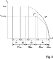
- the determination device 3 is now designed to calculate the maximum speed v max in such a way that the stopping distance d stop,degr in the degraded state, starting from the maximum speed v max,degr in the degraded state, is the same as the stopping distance d stop in the normal state. starting from the maximum speed v max in the normal state. This corresponds to the in figure 3 illustrated scenario.
- the latter expression represents a second-order equation for v max,degr , which is resolved by the determination device 3 accordingly for v max,degr .
- the value obtained by solving this equation is the maximum speed calculated by the determiner 3.
- the device 1 can be designed to control the braking system 4b in such a way that the first braking time TTL is reduced if the determining device 3 detects the deterioration of at least one vehicle component 4 based on the status information.
- the device 1 can control the brake system 4b by means of a control signal in such a way that a hydraulic brake system of the brake system 4b is supplied with a pressure of a predetermined magnitude, for example 5 bar, is pre-filled. This reduces the time it takes to reach full braking power.
- the device 1 can preferably also be designed to output a control signal in order to control the vehicle in such a way that a maximum achievable speed of the vehicle is limited by the specified maximum speed v max .
- the device 1 can comprise a display device which displays the specified maximum speed to the driver of the vehicle.
- the device 1 can be an element of a driver assistance system for a vehicle, which is designed to control the vehicle in such a way that the absolute speed of the vehicle is always less than the maximum speed Vmax.
- FIG 4 Illustrated is an automated driving system 5 for a vehicle F according to an embodiment of the invention.
- the automated driving system 5 includes a device 1 for determining a maximum speed v max for the vehicle F according to one of the embodiments described above.
- the automated driving system 5 also has at least one vehicle component 4 which is coupled to the device 1 and is designed to transmit status information to the device 1 .
- the vehicle component 4 preferably includes, as described above, at least one vehicle sensor 4a, a braking system 4b and a communication system 4c between the braking system 4b and the at least one vehicle sensor 4a.
- the device 1 also includes a determination device 3 which, as described above, is designed to set the maximum speed v max of the vehicle.
- the automated driving system 5 preferably has a control device which is designed to control the vehicle F autonomously, with a driving speed of the vehicle F always being less than the specified maximum speed v max .
- FIG 5 a flowchart for explaining a method for determining a maximum speed for a vehicle F is illustrated.
- a first method step S1 status information about a status of at least one vehicle component 4 of the vehicle F is received.
- a maximum speed v max of the vehicle F is determined using the status information, with a stopping distance of the vehicle F from detection of a dangerous status to standstill of the vehicle F always being less than or equal to a predetermined value.
- the maximum speed v max can be calculated according to one of the embodiments described above.
Landscapes
- Engineering & Computer Science (AREA)
- Transportation (AREA)
- Mechanical Engineering (AREA)
- Automation & Control Theory (AREA)
- Chemical & Material Sciences (AREA)
- Combustion & Propulsion (AREA)
- Regulating Braking Force (AREA)
- Control Of Driving Devices And Active Controlling Of Vehicle (AREA)
Description
- Die vorliegende Erfindung betrifft ein Verfahren zur Festlegung einer Maximalgeschwindigkeit für ein Fahrzeug, eine Vorrichtung zur Festlegung einer Maximalgeschwindigkeit für ein Fahrzeug und ein automatisiertes Fahrsystem für ein Fahrzeug.
- Die Bremsleistung von Notbremsassistenten für Fahrzeuge kann aus mehreren Gründen reduziert sein. So kann sich beispielsweise die Erkennungszeit zur Erkennung von Gefahrensituationen aufgrund schlechter Witterungsbedingungen vergrößern. Weiter kann sich die Kommunikation zwischen den für die Notbremsung erforderlichen Komponenten aufgrund eines Defekts verschlechtern und dadurch die Kommunikationszeit erhöht werden. Schließlich ist auch eine Verschlechterung von hydraulischen Elementen des Bremssystems möglich, sodass sich der Bremsweg verlängert.
- Aus der Druckschrift
DE 10 2013 213 169 A1 ist es bekannt, das Fahrzeug nach Erkennen eines Defekts von Komponenten des Fahrzeugs in einen Notbetrieb zu versetzen und zum Stillstand zu bringen. Aus derDE 10 2014 010085 A1 ist ein Verfahren zum Durchführen eines automatischen Einpark- und/oder Ausparkmanövers eines Fahrzeugs bekannt. DieDE 10 2015 207038 A1 offenbart ein Verfahren zum automatischen Bremsen eines Kraftfahrzeugs beim Parken oder Rangieren. Aus derGB 2310731 A WO 9109275 A2 - Die Erfindung stellt ein Verfahren zur Festlegung einer Maximalgeschwindigkeit für ein Fahrzeug mit den Merkmalen des Patentanspruchs 1, eine Vorrichtung zur Festlegung einer Maximalgeschwindigkeit für ein Fahrzeug mit den Merkmalen des Patentanspruchs 4 und ein automatisiertes Fahrsystem für ein Fahrzeug mit den Merkmalen des Patentanspruchs 7 bereit.
- Gemäß einem ersten Aspekt betrifft die Erfindung demnach ein Verfahren zur Festlegung einer Maximalgeschwindigkeit für ein Fahrzeug, mit den Schritten: Empfangen von Zustandsinformationen über einen Zustand von mindestens einer Fahrzeugkomponente des Fahrzeugs, wobei die Zustandsinformationen Informationen über einen Zustand eines Bremssystems des Fahrzeugs umfassen; Berechnen einer Bremszeit von einem Beginn eines Bremsvorgangs bis zum Stillstand des Fahrzeugs anhand der Informationen über den Zustand des Bremssystems; wobei das Berechnen der Bremszeit das Berechnen einer ersten Bremszeit von einem Beginn des Bremsvorgangs bis zum Erreichen der vollen Bremsleistung, und das Berechnen einer zweiten Bremszeit vom Erreichen der vollen Bremsleistung bis zum Stillstand des Fahrzeugs umfasst; und Festlegen einer Maximalgeschwindigkeit des Fahrzeugs anhand der Zustandsinformationen, derart, dass ein Anhalteweg des Fahrzeugs von einer Erkennung eines Gefahrenzustands bis zum Stillstand des Fahrzeugs kleiner oder gleich einem vorgegebenen Wert ist, wobei die Maximalgeschwindigkeit unter Berücksichtigung der Bremszeit festgelegt wird.
- Gemäß einem weiteren Aspekt betrifft die Erfindung eine Vorrichtung zur Festlegung einer Maximalgeschwindigkeit für ein Fahrzeug, mit einer Eingabeschnittstelle, welche dazu ausgebildet ist, Zustandsinformationen über einen Zustand von mindestens einer Fahrzeugkomponente des Fahrzeugs zu empfangen, wobei die Zustandsinformationen Informationen über einen Zustand eines Bremssystems des Fahrzeugs umfassen; und einer Bestimmungseinrichtung, welche dazu ausgebildet ist, anhand der Informationen über den Zustand des Bremssystems eine Bremszeit von einem Beginn des Bremsvorgangs bis zum Stillstand des Fahrzeugs zu berechnen, wobei das Berechnen der Bremszeit das Berechnen einer ersten Bremszeit von einem Beginn des Bremsvorgangs bis zum Erreichen der vollen Bremsleistung, und das Berechnen einer zweiten Bremszeit vom Erreichen der vollen Bremsleistung bis zum Stillstand des Fahrzeugs umfasst, und wobei die Bestimmungseinrichtung dazu ausgebildet ist, anhand der Zustandsinformationen die Maximalgeschwindigkeit des Fahrzeugs derart festzulegen, dass ein Anhalteweg des Fahrzeugs von einer Erkennung eines Gefahrenzustands bis zum Stillstand des Fahrzeugs kleiner oder gleich einem vorgegebenen Wert ist, wobei die Bestimmungseinrichtung dazu ausgebildet ist, die Maximalgeschwindigkeit unter Berücksichtigung der Bremszeit festzulegen.
- Gemäß einem weiteren Aspekt betrifft die Erfindung ein automatisiertes Fahrsystem für ein Fahrzeug, mit einer Vorrichtung zur Festlegung einer Maximalgeschwindigkeit für das Fahrzeug und mindestens einer Fahrzeugkomponente, welche mit der Vorrichtung gekoppelt ist und dazu ausgebildet ist, Zustandsinformationen an die Vorrichtung zu übertragen.
- Unter Fahrzeugkomponenten des Fahrzeugs werden vorzugsweise Vorrichtungen des Fahrzeugs verstanden, welche für das Abbremsen des Fahrzeugs, beispielsweise durch einen automatisierten Notbremsassistenten, erforderlich sind.
- Die Zustandsinformationen über den Zustand der Fahrzeugkomponenten umfassen vorzugsweise Informationen über eine mögliche Verschlechterung der Fahrzeugkomponenten. Die Zustandsinformationen können auch Informationen über eine Zeit umfassen, welche die entsprechende Fahrzeugkomponente für ihren jeweiligen Beitrag zum Abbremsen des Fahrzeugs benötigt.
- Verschlechtert sich der Zustand von einer oder mehreren Fahrzeugkomponenten, so wird sich im Allgemeinen der Anhalteweg des Fahrzeugs für eine vorgegebene Geschwindigkeit des Fahrzeugs erhöhen. Dadurch kann jedoch im Einzelfall ein sicheres Abbremsen des Fahrzeugs nicht mehr garantiert werden. Erfindungsgemäß wird daher die Maximalgeschwindigkeit des Fahrzeugs derart festgelegt, dass der Anhalteweg einen vorgegebenen Schwellenwert nicht überschreitet. Somit sind ein sicheres Abbremsen und dadurch eine Verhinderung von Unfällen jederzeit möglich.
- Gleichzeitig wird die Maximalgeschwindigkeit vorzugsweise so groß wie möglich gewählt, ohne dass der Anhalteweg jedoch größer als der vorgegebene Wert wird. Dies ermöglicht es dem Fahrer oder einem automatischen Fahrsystem, das Fahrzeug in eine sichere Abstellposition oder zu einer Reparaturwerkstatt zu befördern, ohne jedoch ein Hindernis für andere Verkehrsteilnehmer darzustellen.
- Vorzugsweise umfassen die Zustandsinformationen Informationen über einen Zustand von mindestens einem Fahrzeugsensor des Fahrzeugs, wobei anhand der Informationen über den Zustand des mindestens einen Fahrzeugsensors eine Erkennungszeit berechnet wird, welche zur Erkennung des Gefahrenzustandes benötigt wird. Die Maximalgeschwindigkeit wird unter Berücksichtigung der Erkennungszeit festgelegt. Die Fahrzeugsensoren können beispielsweise Radarsensoren, Infrarotsensoren oder Fahrzeugkameras umfassen, welche ein Fahrzeugumfeld des Fahrzeugs überwachen und zur Erkennung von Objekten im Fahrzeugumfeld ausgebildet sind. Die Informationen über den Zustand können Informationen über eine Erkennungsgenauigkeit des mindestens einen Fahrzeugsensors umfassen, welche beispielsweise anhand von Witterungsbedingungen um das Fahrzeug herum ermittelt werden.
- Gemäß einer Weiterbildung umfassen die Zustandsinformationen Informationen über einen Zustand eines Bremssystems des Fahrzeugs, wobei anhand der Informationen über den Zustand des Bremssystems eine Bremszeit von einem Beginn des Bremsvorgangs bis zum Stillstand des Fahrzeugs berechnet wird und wobei die Maximalgeschwindigkeit unter Berücksichtigung der Bremszeit festgelegt wird.
- Vorzugsweise kann das Berechnen der Bremszeit das Berechnen einer ersten Bremszeit von einem Beginn des Bremsvorgangs bis zum Erreichen der vollen Bremsleistung und das Berechnen einer zweiten Bremszeit vom Erreichen der vollen Bremsleistung bis zum Stillstand des Fahrzeugs umfassen. Beispielsweise kann das Bremssystem ein Antiblockiersystem umfassen. Das Bremssystem kann auch ein Hydrauliksystem umfassen. Die erste Bremszeit entspricht derjenigen Zeit, welche zum Aufbauen des Bremsdrucks des Hydrauliksystems benötigt wird. Die Verzögerung des Fahrzeugs während der Druckaufbauphase ist im Allgemeinen nicht konstant, wohingegen während der zweiten Bremszeit die Verzögerung im Wesentlichen konstant ist.
- Gemäß einer Weiterbildung des Verfahrens können die Zustandsinformationen Informationen über einen Zustand eines Kommunikationssystems zwischen dem Bremssystem und dem mindestens einen Fahrzeugsensor umfassen. Anhand der Informationen über den Zustand des Kommunikationssystems wird eine Kommunikationszeit für die Kommunikation zwischen dem Bremssystem und dem mindestens einen Fahrzeugsensor berechnet und die Maximalgeschwindigkeit wird unter Berücksichtigung der Kommunikationszeit festgelegt. Das erfindungsgemäße Verfahren berücksichtigt somit etwaige Zeitverluste aufgrund einer suboptimalen Kommunikation zwischen den für die Notbremsung erforderlichen Komponenten.
- Gemäß einer Weiterbildung der Vorrichtung umfassen die Zustandsinformationen Informationen über einen Zustand von mindestens einem Fahrzeugsensor des Fahrzeugs, wobei die Bestimmungseinrichtung dazu ausgebildet ist, anhand der Informationen über den Zustand des mindestens einen Fahrzeugsensors eine Erkennungszeit zu berechnen, welche zur Erkennung des Gefahrenzustandes benötigt wird. Die Bestimmungseinrichtung ist weiter dazu ausgebildet, die Maximalgeschwindigkeit unter Berücksichtigung der Erkennungszeit festzulegen.
- Gemäß einer Weiterbildung der Vorrichtung umfassen die Zustandsinformationen Informationen über einen Zustand eines Bremssystems des Fahrzeugs, wobei die Bestimmungseinrichtung dazu ausgebildet ist, anhand der Informationen über den Zustand des Bremssystems eine Bremszeit von einem Beginn des Bremsvorgangs bis zum Stillstand des Fahrzeugs zu berechnen und die Maximalgeschwindigkeit unter Berücksichtigung der Bremszeit festzulegen.
- Gemäß einer Weiterbildung der Vorrichtung ist die Bestimmungseinrichtung dazu ausgebildet ist, zum Berechnen der Bremszeit eine erste Bremszeit von einem Beginn des
- Bremsvorgangs bis zum Erreichen der vollen Bremsleistung zu berechnen, und eine zweite Bremszeit vom Erreichen der vollen Bremsleistung bis zum Stillstand des Fahrzeugs zu berechnen.
- Gemäß einer Weiterbildung der Vorrichtung umfassen die Zustandsinformationen Informationen über einen Zustand eines Kommunikationssystems zwischen dem Bremssystem und dem mindestens einen Fahrzeugsensor, wobei die Bestimmungseinrichtung dazu ausgebildet ist, anhand der Informationen über den Zustand des Kommunikationssystems eine Kommunikationszeit für die Kommunikation zwischen dem Bremssystem und dem mindestens einen Fahrzeugsensor zu berechnen und die Maximalgeschwindigkeit unter Berücksichtigung der Kommunikationszeit festzulegen.
- Es zeigen:
- Figur 1
- ein schematisches Blockdiagramm einer Vorrichtung zur Festlegung einer Maximalgeschwindigkeit für ein Fahrzeug gemäß einer Ausführungsform der Erfindung;
- Figur 2
- eine Illustration eines Anhaltewegs eines Fahrzeugs unter Normalbedingungen bzw. unter verschlechterten Bedingungen bei jeweils gleicher Anfangsgeschwindigkeit;
- Figur 3
- Illustration des Anhaltewegs unter Normalbedingungen bzw. unter verschlechterten Bedingungen und reduzierter Anfangsgeschwindigkeit;
- Figur 4
- ein schematisches Blockdiagramm eines automatisierten Fahrsystems für ein Fahrzeug gemäß einer Ausführungsform der Erfindung; und
- Figur 5
- ein Flussdiagramm zur Erläuterung eines Verfahrens zur Festlegung einer Maximalgeschwindigkeit für ein Fahrzeug gemäß einer Ausführungsform der Erfindung.
- In allen Figuren sind gleiche bzw. funktionsgleiche Elemente und Vorrichtungen mit denselben Bezugszeichen versehen. Verschiedene Ausführungsformen können beliebig miteinander kombiniert werden, sofern dies sinnvoll ist.
-
Figur 1 zeigt ein Blockdiagramm einer Vorrichtung 1 zur Festlegung einer Maximalgeschwindigkeit für ein Fahrzeug. - Die Vorrichtung 1 umfasst eine Eingabeschnittstelle 2, welche dazu ausgebildet ist, Zustandsinformationen über einen Zustand von Fahrzeugkomponenten 4 zu empfangen. Die Eingabeschnittstelle 2 kann hierzu mit den Fahrzeugkomponenten 4 gekoppelt werden. Die Eingabeschnittstelle 2 kann insbesondere über ein Bussystem des Fahrzeugs mit den Fahrzeugkomponenten 4 koppelbar sein.
- Die Vorrichtung 1 umfasst weiter eine Bestimmungseinrichtung 3, welche dazu ausgebildet ist, anhand der Zustandsinformationen die Maximalgeschwindigkeit vmax des Fahrzeugs derart festzulegen, dass ein Anhalteweg danhalte des Fahrzeugs von einer Erkennung eines Gefahrenzustands bis zum Stillstand des Fahrzeugs kleiner oder gleich einem vorgegebenen Wert ist.
- Die Fahrzeugkomponenten 4 umfassen mindestens einen Fahrzeugsensor 4a, welcher Radarsensoren, Infrarotsensoren oder Fahrzeugkameras umfassen kann. Der Fahrzeugsensor 4a ist zum Bereitstellen von Sensordaten bzw. Umfelddaten bezüglich eines Fahrzeugumfelds des Fahrzeugs ausgebildet. Der Fahrzeugsensor 4a umfasst vorzugsweise eine Erkennungseinrichtung, welche dazu ausgebildet ist, anhand der Sensordaten eine Gefahrensituation zu erkennen.
- Die Fahrzeugkomponenten 4 umfassen weiter ein Bremssystem 4b, welches dazu ausgebildet ist, das Fahrzeug abzubremsen. Das Bremssystem 4b umfasst vorzugsweise ein hydraulisches Bremssystem, beispielsweise ein Plunger-basiertes Bremssystem oder ein Kolbenbremssystem. Das Bremssystem kann weiter ein Antiblockiersystem umfassen. Das Bremssystem kann ein automatisches Bremssystem umfassen, welches bei einer Erkennung eines Gefahrenzustands durch den mindestens einen Fahrzeugsensor 4a automatisch das Fahrzeug bis zum Stillstand abbremst.
- Die Fahrzeugkomponenten 4 umfassen weiter ein Kommunikationssystem 4c, welches mit dem Bremssystem 4b und dem mindestens einen Fahrzeugsensor 4a gekoppelt ist und dazu ausgebildet ist, Informationen von dem mindestens einen Fahrzeugsensor 4a, gegebenenfalls über mindestens ein Steuergerät, an das Bremssystem 4b zu übertragen. Das Kommunikationssystem 4c kann ein Bussystem des Fahrzeugs umfassen.
- Die Fahrzeugkomponenten 4a, 4b, 4c können vorzugsweise jeweils entsprechende Informationen über den Zustand der jeweiligen Fahrzeugkomponente 4a, 4b, 4c bereitstellen und an die Eingabeschnittstelle 2 übertragen.
- Diese Zustandsinformationen können beispielsweise Informationen über einen Zustand des mindestens einen Fahrzeugsensors 4a umfassen. Diese können beispielsweise eine Erkennungszeit TD ("time to detect") umfassen, welche der mindestens eine Fahrzeugsensor 4a benötigt, um ein Objekt, etwa einen Fußgänger, sensorisch zu erfassen, zu klassifizieren, und einen Gefahrenzustand zu erkennen. Die Erkennungszeit TD entspricht somit derjenigen Zeit, welche zur Erkennung des Gefahrenzustandes durch den Fahrzeugsensor 4a benötigt wird. Falls nun mindestens einer der Fahrzeugsensoren 4a aufgrund eines Defekts ausfällt oder aufgrund von geänderten Umgebungsbedingungen, beispielsweise schlechter Witterungsverhältnisse, eine geringere Erkennungsgenauigkeit aufweist, so reduziert sich die Erkennungszeit TD entsprechend. Die Informationen über den Zustand des mindestens einen Fahrzeugsensors 4a können die derart reduzierte Erkennungszeit TD umfassen. Die Informationen über den Zustand des mindestens einen Fahrzeugsensors 4a können jedoch auch Informationen bezüglich eines Defekts oder bezüglich der Betriebszustände des Fahrzeugsensors 4a umfassen, wobei die Bestimmungseinrichtung 3 dazu ausgebildet ist, die Erkennungszeit TD anhand dieser Informationen zu berechnen.
- Die Zustandsinformationen können weiter Informationen über einen Zustand des Bremssystems 4b umfassen, beispielsweise Informationen, ob sich das Bremssystem 4b in einem Normalzustand oder in einem verschlechterten Zustand befindet. Die Bestimmungseinrichtung 3 ist dazu ausgebildet, anhand der Informationen über den Zustand des Bremssystems 4b eine Bremszeit TB ("time to break") von einem Beginn des Bremsvorgangs bis zum Stillstand des Fahrzeugs zu berechnen. Die Bestimmungseinrichtung 3 berechnet hierbei eine erste Bremszeit TTL ("time to lock"), von einem Beginn des Bremsvorgangs bis zum Erreichen der vollen Bremsleistung. Bei einem hydraulischen Bremssystem entspricht dies derjenigen Zeit, welche zum Aufbauen des vollständigen Bremsdrucks benötigt wird. Weiter berechnet die Bestimmungseinrichtung 3 eine zweite Bremszeit Tstop vom Erreichen der vollen Bremsleistung bis zum Stillstand des Fahrzeugs. Dies entspricht derjenigen Zeit, welche das Bremssystem zum Abbremsen des Fahrzeugs bei vollem Bremsdrucks benötigt. Die Bremszeit TB entspricht der Summe der ersten Bremszeit TTL und der zweiten Bremszeit Tstop.
- Weiter umfassen die Zustandsinformationen Informationen über einen Zustand des Kommunikationssystems 4c, wobei die Bestimmungseinrichtung 3 dazu ausgebildet ist, anhand der Informationen über den Zustand des Kommunikationssystems 4c eine Kommunikationszeit TT ("time to travel") für die Kommunikation zwischen dem Bremssystem 4b und dem mindestens einen Fahrzeugsensor 4a zu berechnen.
- Die jeweiligen Zustandsinformationen können mittels Erkennungsalgorithmen durch die jeweiligen Fahrzeugkomponenten 4 selbst ermittelt werden. Die Zustandsinformationen können jedoch auch mittels einer Sensoreinrichtung der Vorrichtung 1 ermittelt werden.
- Gemäß weiteren Ausführungsformen können die Zustandsinformationen bereits die Erkennungszeit TD, die Bremszeit TB und/oder die Kommunikationszeit TT selbst umfassen.
- Die Bestimmungseinrichtung 3 ist dazu ausgebildet, einen maximalen Anhalteweg danhalte des Fahrzeugs, welches sich anfänglich mit einer Maximalgeschwindigkeit vmax bewegt, anhand folgender Formel zu berechnen:

- Das erste Anhaltewegsegment d1 entspricht der während der Erkennungszeit TD zurückgelegten Strecke, das zweite Anhaltewegsegment d2 entspricht der während der Kommunikationszeit TT zurückgelegten Strecke, das dritte Anhaltewegsegment d3 entspricht der während der ersten Bremszeit TTL zurückgelegten Strecke und das vierte Anhaltewegsegment D4 entspricht der während der zweiten Bremszeit Tstop zurückgelegten Strecke.
- Die Größe aTTL = k·TTL ist die Verzögerung während der Druckaufbauphase, wobei k = amax/TTL die lineare Steigung darstellt. Hierbei ist amax die maximale Verzögerung, welche das Bremssystem 4b während der zweiten Bremszeit Tstop auf das Fahrzeug ausübt. Die erste Integration von aTTL ist vTTL = 1/2·k·TTL2 und die zweite Integration ist dTTL = 1/6·k·TTL3, was dem zweiten Term des dritten Anhaltewegsegments d3 entspricht.
- Während hier ein linearer Verlauf für die die Verzögerung angenommen wird, kann die Bestimmungseinrichtung 3 in Abhängigkeit von der Charakteristik des Bremssystems 4b auch eine nichtlineare Abhängigkeit der Verzögerung von der ersten Bremszeit TTL berücksichtigen, wobei sich die jeweiligen Formen entsprechend modifizieren.
- Weiter ist vrest = vmax - 1/2·k·TTL2 die Restgeschwindigkeit nach vollzogenem Druckaufbau, d. h. nach der ersten Bremszeit TTL. Einsetzen dieser Beziehung in die Gleichung für den Anhalteweg danhalte ergibt folgende Beziehung:

- In einem fehlerhaften bzw. degradierten Zustand können die erste Bremszeit TTL, die zweite Bremszeit Tstop, die Erkennungszeit TD und die Kommunikationszeit TT sowie die maximale Verzögerung amax von den entsprechenden Werten im Normalzustand abweichen. Die Bestimmungseinrichtung 3 berechnet im degradierten Zustand den Anhalteweg danhalte nach folgender Formel, wobei die Maximalgeschwindigkeit vmax,degr einen freien Parameter darstellt:

- Der Index "degr" steht hierbei für den Wert der jeweiligen Größe im degradierten Zustand.
- Wird die Maximalgeschwindigkeit vmax des Fahrzeugs nicht verändert, also falls gilt, dass vmax = vmax,degr, so ergibt sich das in
Figur 2 illustrierte Szenario. Im Normalzustand ergibt sich der in Kurve y1 gezeigte Verlauf der Geschwindigkeit v in Abhängigkeit von der zurückgelegten Strecke d. Aufgrund der im degradierten Zustand verlängerten Anhaltewegsegmente d1degr, d2degr, d3degr, d4degr verlängert sich der gesamte Anhalteweg, wie dem in Kurve y2 gezeigten Verlauf der Geschwindigkeit v zu entnehmen ist. - Die Bestimmungseinrichtung 3 ist nun dazu ausgelegt, die Maximalgeschwindigkeit vmax derart zu berechnen, dass der Anhalteweg danhalte, degr im degradierten Zustand, ausgehend von der Maximalgeschwindigkeit vmax,degr im degradierten Zustand, gleich groß ist wie der Anhalteweg danhalte im Normalzustand, ausgehend von der Maximalgeschwindigkeit vmax im Normalzustand. Dies entspricht dem in
Figur 3 illustrierten Szenario. - Die Bestimmungseinrichtung 3 berechnet somit die Maximalgeschwindigkeit vmax unter der Bedingung danhalte = danhalte,degr. Durch Einsetzen und Umschreiben erhält man zuerst folgende Gleichung:


- Letzterer Ausdruck stellt eine Gleichung zweiter Ordnung für vmax,degr dar, welche von der Bestimmungseinrichtung 3 entsprechend nach vmax,degr aufgelöst wird. Der durch Lösen dieser Gleichung erhaltene Wert ist die von der Bestimmungseinrichtung 3 berechnete Maximalgeschwindigkeit.
- Gemäß einer Weiterbildung kann die Vorrichtung 1 dazu ausgebildet sein, das Bremssystem 4b derart anzusteuern, dass die erste Bremszeit TTL reduziert wird, wenn die Bestimmungseinrichtung 3 anhand der Zustandsinformationen die Verschlechterung von mindestens einer Fahrzeugkomponente 4 erkennt. So kann die Vorrichtung 1 das Bremssystem 4b mittels eines Steuersignals derart ansteuern, dass eine hydraulische Bremsanlage des Bremssystems 4b mit einem Druck mit vorgegebener Größe, beispielsweise von 5 bar, vorbefüllt wird. Dadurch wird die Zeit, welche zum Erreichen der vollen Bremsleistung benötigt wird, reduziert.
- Vorzugsweise kann die Vorrichtung 1 weiter dazu ausgebildet sein, ein Steuersignal auszugeben, um das Fahrzeug derart anzusteuern, dass eine maximal erreichbare Geschwindigkeit des Fahrzeugs durch die festgelegte Maximalgeschwindigkeit vmax begrenzt ist.
- Weiter kann die Vorrichtung 1 eine Anzeigeeinrichtung umfassen, welche die festgelegte Maximalgeschwindigkeit dem Fahrer des Fahrzeugs anzeigt.
- Die Vorrichtung 1 kann ein Element eines Fahrerassistenzsystems für ein Fahrzeug sein, welches dazu ausgebildet ist, das Fahrzeug derart zu steuern, dass die Absolutgeschwindigkeit des Fahrzeugs stets kleiner ist als die Maximalgeschwindigkeit Vmax.
- In
Figur 4 ist ein automatisiertes Fahrsystem 5 für ein Fahrzeug F gemäß einer Ausführungsform der Erfindung illustriert. Das automatisierte Fahrsystem 5 umfasst eine Vorrichtung 1 zur Festlegung einer Maximalgeschwindigkeit vmax für das Fahrzeug F gemäß einer der oben beschriebenen Ausführungsformen. Das automatisierte Fahrsystem 5 weist weiter mindestens eine Fahrzeugkomponente 4 auf, welche mit der Vorrichtung 1 gekoppelt ist und dazu ausgebildet ist, Zustandsinformationen an die Vorrichtung 1 zu übertragen. Die Fahrzeugkomponente 4 umfasst vorzugsweise wie oben beschrieben mindestens einen Fahrzeugsensor 4a, ein Bremssystem 4b und ein Kommunikationssystems 4c zwischen dem Bremssystem 4b und dem mindestens einen Fahrzeugsensor 4a. - Die Vorrichtung 1 umfasst weiter eine Bestimmungseinrichtung 3, welche, wie oben beschrieben, dazu ausgebildet ist, die Maximalgeschwindigkeit vmax des Fahrzeugs festzulegen.
- Das automatisierte Fahrsystem 5 weist vorzugsweise eine Steuereinrichtung auf, welche dazu ausgebildet ist, das Fahrzeug F autonom zu steuern, wobei eine Fahrgeschwindigkeit des Fahrzeugs F stets kleiner als die festgelegte Maximalgeschwindigkeit vmax ist.
- In
Figur 5 ist ein Flussdiagramm zur Erläuterung eines Verfahrens zur Festlegung einer Maximalgeschwindigkeit für ein Fahrzeug F illustriert. - In einem ersten Verfahrensschritt S1 werden Zustandsinformationen über einen Zustand von mindestens einer Fahrzeugkomponente 4 des Fahrzeugs F empfangen.
- In einem weiteren Verfahrensschritt S2 wird eine Maximalgeschwindigkeit vmax des Fahrzeugs F anhand der Zustandsinformationen festgelegt, wobei ein Anhalteweg des Fahrzeugs F von einer Erkennung eines Gefahrenzustands bis zum Stillstand des Fahrzeugs F stets kleiner oder gleich einem vorgegebenen Wert ist. Die Berechnung der Maximalgeschwindigkeit vmax kann nach einer der oben beschriebenen Ausführungsformen durchgeführt werden.
Claims (7)
- Verfahren zur Festlegung einer Maximalgeschwindigkeit (vmax) für ein Fahrzeug (F), mit den Schritten:Empfangen (S1) von Zustandsinformationen über einen Zustand von mindestens einer Fahrzeugkomponente (4) des Fahrzeugs (F), wobei die Zustandsinformationen Informationen über einen Zustand eines Bremssystems (4b) des Fahrzeugs (F) umfassen;Berechnen einer Bremszeit (TB) von einem Beginn eines Bremsvorgangs bis zum Stillstand des Fahrzeugs (F) anhand der Informationen über den Zustand des Bremssystems (4b);wobei das Berechnen der Bremszeit (TB) das Berechnen einer ersten Bremszeit (TTL) von einem Beginn des Bremsvorgangs bis zum Erreichen der vollen Bremsleistung, und das Berechnen einer zweiten Bremszeit (Tstop) vom Erreichen der vollen Bremsleistung bis zum Stillstand des Fahrzeugs (F) umfasst; undFestlegen (S2) einer Maximalgeschwindigkeit (vmax) des Fahrzeugs anhand der Zustandsinformationen, derart, dass ein Anhalteweg (danhalte) des Fahrzeugs (F) von einer Erkennung eines Gefahrenzustands bis zum Stillstand des Fahrzeugs (F) kleiner oder gleich einem vorgegebenen Wert ist, wobei die Maximalgeschwindigkeit (vmax) unter Berücksichtigung der Bremszeit (TB) festgelegt wird.
- Verfahren nach Anspruch 1, wobei die Zustandsinformationen Informationen über einen Zustand von mindestens einem Fahrzeugsensor (4a) des Fahrzeugs (F) umfassen, und wobei anhand der Informationen über den Zustand des mindestens einen Fahrzeugsensors (4a) eine Erkennungszeit (TD) berechnet wird, welche zur Erkennung des Gefahrenzustandes benötigt wird, und die Maximalgeschwindigkeit (vmax) unter Berücksichtigung der Erkennungszeit (TD) festgelegt wird.
- Verfahren nach Anspruch 2, wobei die Zustandsinformationen Informationen über einen Zustand eines Kommunikationssystems (4c) zwischen dem Bremssystem (4b) und dem mindestens einem Fahrzeugsensor (4a) umfassen, und wobei anhand der Informationen über den Zustand des Kommunikationssystems (4c) eine Kommunikationszeit (TT) für die Kommunikation zwischen dem Bremssystem (4b) und dem mindestens einen Fahrzeugsensor (4a) berechnet wird und die Maximalgeschwindigkeit (vmax) unter Berücksichtigung der Kommunikationszeit (TT) festgelegt wird.
- Vorrichtung (1) zur Festlegung einer Maximalgeschwindigkeit (vmax) für ein Fahrzeug (F), mit:einer Eingabeschnittstelle (2), welche dazu ausgebildet ist, Zustandsinformationen über einen Zustand von mindestens einer Fahrzeugkomponente (4) des Fahrzeugs (F) zu empfangen, wobei die Zustandsinformationen Informationen über einen Zustand eines Bremssystems (4b) des Fahrzeugs (F) umfassen; undeiner Bestimmungseinrichtung (3), welche dazu ausgebildet ist, anhand der Informationen über den Zustand des Bremssystems (4b) eine Bremszeit (TB) von einem Beginn des Bremsvorgangs bis zum Stillstand des Fahrzeugs (F) zu berechnen, wobei das Berechnen der Bremszeit (TB) das Berechnen einer ersten Bremszeit (TTL) von einem Beginn des Bremsvorgangs bis zum Erreichen der vollen Bremsleistung, und das Berechnen einer zweiten Bremszeit (Tstop) vom Erreichen der vollen Bremsleistung bis zum Stillstand des Fahrzeugs (F) umfasst, und wobei die Bestimmungseinrichtung (3) dazu ausgebildet ist, anhand der Zustandsinformationen die Maximalgeschwindigkeit (vmax) des Fahrzeugs derart festzulegen, dass ein Anhalteweg (danhalte) des Fahrzeugs (F) von einer Erkennung eines Gefahrenzustands bis zum Stillstand des Fahrzeugs (F) kleiner oder gleich einem vorgegebenen Wert ist, wobei die Bestimmungseinrichtung (3) dazu ausgebildet ist, die Maximalgeschwindigkeit (vmax) unter Berücksichtigung der Bremszeit (TB) festzulegen.
- Vorrichtung (1) nach Anspruch 4, wobei die Zustandsinformationen Informationen über einen Zustand von mindestens einem Fahrzeugsensor (4a) des Fahrzeugs (F) umfassen, und wobei die Bestimmungseinrichtung (3) dazu ausgebildet ist, anhand der Informationen über den Zustand des mindestens einen Fahrzeugsensors (4a) eine Erkennungszeit (TD) zu berechnen, welche zur Erkennung des Gefahrenzustandes benötigt wird, und die Maximalgeschwindigkeit (vmax) unter Berücksichtigung der Erkennungszeit (TD) festzulegen.
- Vorrichtung (1) nach Anspruch 4 oder 5, wobei die Zustandsinformationen Informationen über einen Zustand eines Kommunikationssystems (4c) zwischen dem Bremssystem (4b) und dem mindestens einem Fahrzeugsensor (4a) umfassen, und wobei die Bestimmungseinrichtung (3) dazu ausgebildet ist, anhand der Informationen über den Zustand des Kommunikationssystems (4c) eine Kommunikationszeit (TT) für die Kommunikation zwischen dem Bremssystem (4b) und dem mindestens einen Fahrzeugsensor (4a) zu berechnen und die Maximalgeschwindigkeit (vmax) unter Berücksichtigung der Kommunikationszeit (TT) festzulegen.
- Automatisiertes Fahrsystem (5) für ein Fahrzeug (F), miteiner Vorrichtung (1) zur Festlegung einer Maximalgeschwindigkeit (vmax) für das Fahrzeug (F) nach einem der Ansprüche 4 bis 6; undmindestens einer Fahrzeugkomponente (4), welche mit der Vorrichtung (1) gekoppelt ist und dazu ausgebildet ist, Zustandsinformationen an die Vorrichtung (1) zu übertragen.
Applications Claiming Priority (2)
| Application Number | Priority Date | Filing Date | Title |
|---|---|---|---|
| DE102017202363.5A DE102017202363A1 (de) | 2017-02-15 | 2017-02-15 | Verfahren und Vorrichtung zur Festlegung einer Maximalgeschwindigkeit für ein Fahrzeug und automatisiertes Fahrsystem |
| PCT/EP2017/082618 WO2018149536A1 (de) | 2017-02-15 | 2017-12-13 | Verfahren und vorrichtung zur festlegung einer maximalgeschwindigkeit für ein fahrzeug und automatisiertes fahrsystem |
Publications (2)
| Publication Number | Publication Date |
|---|---|
| EP3583009A1 EP3583009A1 (de) | 2019-12-25 |
| EP3583009B1 true EP3583009B1 (de) | 2022-08-10 |
Family
ID=60788588
Family Applications (1)
| Application Number | Title | Priority Date | Filing Date |
|---|---|---|---|
| EP17818510.4A Active EP3583009B1 (de) | 2017-02-15 | 2017-12-13 | Verfahren und vorrichtung zur festlegung einer maximalgeschwindigkeit für ein fahrzeug und automatisiertes fahrsystem |
Country Status (6)
| Country | Link |
|---|---|
| US (1) | US11305758B2 (de) |
| EP (1) | EP3583009B1 (de) |
| JP (1) | JP7021262B2 (de) |
| CN (1) | CN110300690B (de) |
| DE (1) | DE102017202363A1 (de) |
| WO (1) | WO2018149536A1 (de) |
Families Citing this family (3)
| Publication number | Priority date | Publication date | Assignee | Title |
|---|---|---|---|---|
| CN110341716B (zh) * | 2019-08-06 | 2020-12-18 | 浙江吉利汽车研究院有限公司 | 车速计算方法、装置、自动驾驶系统及存储介质 |
| DE102020121831A1 (de) * | 2020-08-20 | 2022-02-24 | Zf Cv Systems Global Gmbh | Verfahren zum Sichern eines Fahrzeugs |
| WO2023284982A1 (en) * | 2021-07-16 | 2023-01-19 | Volvo Autonomous Solutions AB | A method for controlling a maximum allowed speed of an autonomous vehicle |
Family Cites Families (25)
| Publication number | Priority date | Publication date | Assignee | Title |
|---|---|---|---|---|
| JPS59203975A (ja) * | 1983-05-06 | 1984-11-19 | Nissan Motor Co Ltd | 車両用光レ−ダ装置 |
| WO1991009375A1 (en) | 1989-12-11 | 1991-06-27 | Caterpillar Inc. | Integrated vehicle positioning and navigation system, apparatus and method |
| DE19607788B4 (de) | 1996-03-01 | 2009-05-07 | Robert Bosch Gmbh | Verfahren und Vorrichtung zur Steuerung der Annäherung eines Fahrzeugs an ein Hindernis |
| DE19831262C2 (de) * | 1998-07-11 | 2002-09-19 | Wabco Gmbh & Co Ohg | Einrichtung zur Unterstützung des Fahrers eines Nutzfahrzeuges bei Rückwärtsfahrt |
| JP4848027B2 (ja) | 2004-01-30 | 2011-12-28 | 日立オートモティブシステムズ株式会社 | 車両制御装置 |
| DE102004047177A1 (de) | 2004-09-29 | 2006-04-13 | Robert Bosch Gmbh | Anfahrassistent für Kraftfahrzeuge |
| US20060100783A1 (en) | 2004-10-21 | 2006-05-11 | Sick Ag | Monitoring the surroundings of a vehicle |
| JP4301331B2 (ja) * | 2007-09-11 | 2009-07-22 | トヨタ自動車株式会社 | 車両用駆動装置の制御装置 |
| DE102008042962A1 (de) * | 2008-10-20 | 2010-04-22 | Robert Bosch Gmbh | Verfahren zur Einstellung eines Bremssystems eines Fahrzeugs |
| JP5135321B2 (ja) * | 2009-11-13 | 2013-02-06 | 株式会社日立製作所 | 自律走行装置 |
| JP5507433B2 (ja) | 2010-12-21 | 2014-05-28 | ダイハツ工業株式会社 | 運転支援装置 |
| WO2013011058A1 (de) * | 2011-07-19 | 2013-01-24 | Continental Teves Ag & Co. Ohg | Verfahren zur verbesserung der fahrstabilität |
| AU2013101329A4 (en) * | 2012-10-10 | 2013-10-31 | General Electric Company | Systems and methods for vehicle braking control |
| DE102013224313A1 (de) * | 2013-03-05 | 2014-09-11 | Continental Teves Ag & Co. Ohg | Verfahren zum Betreiben eines Bremssystems |
| DE102013213169A1 (de) | 2013-07-04 | 2015-01-08 | Robert Bosch Gmbh | Verfahren und Vorrichtung zum Betreiben eines Kraftfahrzeugs in einem automatisierten Fahrbetrieb |
| KR20150062490A (ko) * | 2013-11-29 | 2015-06-08 | 주식회사 만도 | 차량의 차속 제어 장치 및 방법 |
| US9499140B2 (en) * | 2014-01-29 | 2016-11-22 | Continental Automotive Systems, Inc. | Method for reducing jerk when completing an automatic braking maneuver |
| DE102014010085A1 (de) | 2014-07-08 | 2015-01-15 | Daimler Ag | Verfahren zum Durchführen eines automatischen Einpark- und/oder Ausparkmanövers eines Fahrzeugs |
| JP2016016812A (ja) | 2014-07-10 | 2016-02-01 | 高周波粘弾性株式会社 | 運転制御装置、自動車及び運転制御方法 |
| CN107206907B (zh) * | 2014-11-24 | 2020-02-14 | 极步公司 | 机动车轮的设备和方法 |
| JP6496585B2 (ja) | 2015-03-24 | 2019-04-03 | クラリオン株式会社 | 物体認識装置 |
| DE102015207038A1 (de) | 2015-04-17 | 2016-10-20 | Bayerische Motoren Werke Aktiengesellschaft | Verfahren und Bremsassistenzsystem zum automatischen Bremsen eines Kraftfahrzeuges beim Parken oder Rangieren |
| CN105196910B (zh) * | 2015-09-15 | 2018-06-26 | 浙江吉利汽车研究院有限公司 | 一种雨雾天气下的安全驾驶辅助系统及其控制方法 |
| JP6426579B2 (ja) * | 2015-09-30 | 2018-11-21 | 株式会社アドヴィックス | 車両用制動装置 |
| KR102585219B1 (ko) * | 2016-11-29 | 2023-10-05 | 삼성전자주식회사 | 차량 속도 제어 방법 및 장치 |
-
2017
- 2017-02-15 DE DE102017202363.5A patent/DE102017202363A1/de not_active Withdrawn
- 2017-12-13 CN CN201780086606.3A patent/CN110300690B/zh active Active
- 2017-12-13 JP JP2019564578A patent/JP7021262B2/ja active Active
- 2017-12-13 US US16/485,694 patent/US11305758B2/en active Active
- 2017-12-13 WO PCT/EP2017/082618 patent/WO2018149536A1/de not_active Ceased
- 2017-12-13 EP EP17818510.4A patent/EP3583009B1/de active Active
Also Published As
| Publication number | Publication date |
|---|---|
| CN110300690B (zh) | 2023-03-14 |
| DE102017202363A1 (de) | 2018-08-16 |
| US11305758B2 (en) | 2022-04-19 |
| US20200001866A1 (en) | 2020-01-02 |
| EP3583009A1 (de) | 2019-12-25 |
| JP7021262B2 (ja) | 2022-02-16 |
| CN110300690A (zh) | 2019-10-01 |
| WO2018149536A1 (de) | 2018-08-23 |
| JP2020507518A (ja) | 2020-03-12 |
Similar Documents
| Publication | Publication Date | Title |
|---|---|---|
| DE102016209833B4 (de) | Verfahren und Vorrichtung zum Bestimmen eines Fahrerhandmoments an einem Lenkrad eines Fahrzeugs | |
| DE112017006397B4 (de) | System für ein Fahrzeug | |
| EP3625093B1 (de) | Verfahren und steuereinrichtung zur autonomen notbremsung eines ego-fahrzeugs | |
| EP3148855B1 (de) | Bestimmen eines kritischen fahrzeugzustands | |
| DE102007019991A1 (de) | Vermeidung eines Auffahrunfalls bei einem automatischen Bremseingriff eines Fahrzeugsicherheitssystems | |
| WO2016155905A1 (de) | Verfahren zum mindestens teilautomatisierten fahren in einem fahrzeug | |
| EP3583009B1 (de) | Verfahren und vorrichtung zur festlegung einer maximalgeschwindigkeit für ein fahrzeug und automatisiertes fahrsystem | |
| WO2018210500A1 (de) | Verfahren zum ermitteln einer autonomen notbremsung, verfahren zur durchführung der notbremsung, und steuereinrichtung für ein fahrdynamiksystem | |
| DE102015201981A1 (de) | Verfahren und Vorrichtung zum sicheren Abschleppen eines Fahrzeugs | |
| EP2432670B1 (de) | Bremssystem mit dauerbremsintegration | |
| DE102015216679A1 (de) | Notbremsassistent für ein Fahrzeug | |
| EP2655150B1 (de) | Verfahren zur kalibrierung eines aus einem drucksensorsignal berechneten aussteuerpunktes eines pneumatischen bremskraftverstärkers | |
| DE102015209217B3 (de) | Verfahren und System zum Bereitstellen einer Trajektorie zur Vermeidung einer Fahrzeugkollision | |
| DE102017109175A1 (de) | Steuereinrichtung, Fahrerassistenzsystem, Kraftfahrzeug und Verfahren zum Steuern einer Fahrerassistenzfunktion | |
| DE102010021872A1 (de) | Verfahren zur Ansteuerung einer Bremsvorrichtung eines Kraftfahrzeugs | |
| DE102014221835A1 (de) | Verfahren und Vorrichtung zur Fahrzeugsteuerung | |
| DE102014225085B4 (de) | Verfahren und Vorrichtung zur Ermittlung des Reibwertes einer Fahrbahnoberfläche | |
| EP2900528B1 (de) | Verfahren und vorrichtung zum betrieb eines fahrzeuges und fahrzeug mit einer solchen vorrichtung | |
| WO2017207133A1 (de) | Verfahren und vorrichtung zur längsdynamikregelung bei einem kraftfahrzeug während eines autonomen fahrvorgangs | |
| DE102013214401A1 (de) | Verfahren und Vorrichtung zum Betreiben eines Fahrerassistenzsystems | |
| DE10345748B4 (de) | Verfahren zum Erkennen des Andockens von Fahrzeugen | |
| DE102017216457A1 (de) | Verfahren zur Bestimmung einer maximalen Geschwindigkeit eines Fahrzeugs während eines Einparkmanövers | |
| DE102014220427B3 (de) | Modellbasierter Abbruch einer automatischen Bremsung | |
| DE102009003203A1 (de) | Verfahren und Einrichtung für Erfassung eines Ausweichvorgangs eines Fahrzeugs | |
| DE102011105949A1 (de) | Verfahren und Vorrichtung zur Müdigkeits- und/oder Aufmerksamkeitsbeurteilung |
Legal Events
| Date | Code | Title | Description |
|---|---|---|---|
| STAA | Information on the status of an ep patent application or granted ep patent |
Free format text: STATUS: UNKNOWN |
|
| STAA | Information on the status of an ep patent application or granted ep patent |
Free format text: STATUS: THE INTERNATIONAL PUBLICATION HAS BEEN MADE |
|
| PUAI | Public reference made under article 153(3) epc to a published international application that has entered the european phase |
Free format text: ORIGINAL CODE: 0009012 |
|
| STAA | Information on the status of an ep patent application or granted ep patent |
Free format text: STATUS: REQUEST FOR EXAMINATION WAS MADE |
|
| 17P | Request for examination filed |
Effective date: 20190916 |
|
| AK | Designated contracting states |
Kind code of ref document: A1 Designated state(s): AL AT BE BG CH CY CZ DE DK EE ES FI FR GB GR HR HU IE IS IT LI LT LU LV MC MK MT NL NO PL PT RO RS SE SI SK SM TR |
|
| AX | Request for extension of the european patent |
Extension state: BA ME |
|
| RAP1 | Party data changed (applicant data changed or rights of an application transferred) |
Owner name: ROBERT BOSCH GMBH |
|
| DAV | Request for validation of the european patent (deleted) | ||
| DAX | Request for extension of the european patent (deleted) | ||
| GRAP | Despatch of communication of intention to grant a patent |
Free format text: ORIGINAL CODE: EPIDOSNIGR1 |
|
| STAA | Information on the status of an ep patent application or granted ep patent |
Free format text: STATUS: GRANT OF PATENT IS INTENDED |
|
| INTG | Intention to grant announced |
Effective date: 20220510 |
|
| GRAS | Grant fee paid |
Free format text: ORIGINAL CODE: EPIDOSNIGR3 |
|
| GRAA | (expected) grant |
Free format text: ORIGINAL CODE: 0009210 |
|
| STAA | Information on the status of an ep patent application or granted ep patent |
Free format text: STATUS: THE PATENT HAS BEEN GRANTED |
|
| AK | Designated contracting states |
Kind code of ref document: B1 Designated state(s): AL AT BE BG CH CY CZ DE DK EE ES FI FR GB GR HR HU IE IS IT LI LT LU LV MC MK MT NL NO PL PT RO RS SE SI SK SM TR |
|
| REG | Reference to a national code |
Ref country code: AT Ref legal event code: REF Ref document number: 1510322 Country of ref document: AT Kind code of ref document: T Effective date: 20220815 Ref country code: CH Ref legal event code: EP |
|
| REG | Reference to a national code |
Ref country code: IE Ref legal event code: FG4D Free format text: LANGUAGE OF EP DOCUMENT: GERMAN |
|
| REG | Reference to a national code |
Ref country code: DE Ref legal event code: R096 Ref document number: 502017013611 Country of ref document: DE |
|
| REG | Reference to a national code |
Ref country code: SE Ref legal event code: TRGR |
|
| REG | Reference to a national code |
Ref country code: NL Ref legal event code: MP Effective date: 20220810 |
|
| REG | Reference to a national code |
Ref country code: LT Ref legal event code: MG9D |
|
| PG25 | Lapsed in a contracting state [announced via postgrant information from national office to epo] |
Ref country code: RS Free format text: LAPSE BECAUSE OF FAILURE TO SUBMIT A TRANSLATION OF THE DESCRIPTION OR TO PAY THE FEE WITHIN THE PRESCRIBED TIME-LIMIT Effective date: 20220810 Ref country code: PT Free format text: LAPSE BECAUSE OF FAILURE TO SUBMIT A TRANSLATION OF THE DESCRIPTION OR TO PAY THE FEE WITHIN THE PRESCRIBED TIME-LIMIT Effective date: 20221212 Ref country code: NO Free format text: LAPSE BECAUSE OF FAILURE TO SUBMIT A TRANSLATION OF THE DESCRIPTION OR TO PAY THE FEE WITHIN THE PRESCRIBED TIME-LIMIT Effective date: 20221110 Ref country code: NL Free format text: LAPSE BECAUSE OF FAILURE TO SUBMIT A TRANSLATION OF THE DESCRIPTION OR TO PAY THE FEE WITHIN THE PRESCRIBED TIME-LIMIT Effective date: 20220810 Ref country code: LV Free format text: LAPSE BECAUSE OF FAILURE TO SUBMIT A TRANSLATION OF THE DESCRIPTION OR TO PAY THE FEE WITHIN THE PRESCRIBED TIME-LIMIT Effective date: 20220810 Ref country code: LT Free format text: LAPSE BECAUSE OF FAILURE TO SUBMIT A TRANSLATION OF THE DESCRIPTION OR TO PAY THE FEE WITHIN THE PRESCRIBED TIME-LIMIT Effective date: 20220810 Ref country code: FI Free format text: LAPSE BECAUSE OF FAILURE TO SUBMIT A TRANSLATION OF THE DESCRIPTION OR TO PAY THE FEE WITHIN THE PRESCRIBED TIME-LIMIT Effective date: 20220810 |
|
| PG25 | Lapsed in a contracting state [announced via postgrant information from national office to epo] |
Ref country code: PL Free format text: LAPSE BECAUSE OF FAILURE TO SUBMIT A TRANSLATION OF THE DESCRIPTION OR TO PAY THE FEE WITHIN THE PRESCRIBED TIME-LIMIT Effective date: 20220810 Ref country code: IS Free format text: LAPSE BECAUSE OF FAILURE TO SUBMIT A TRANSLATION OF THE DESCRIPTION OR TO PAY THE FEE WITHIN THE PRESCRIBED TIME-LIMIT Effective date: 20221210 Ref country code: HR Free format text: LAPSE BECAUSE OF FAILURE TO SUBMIT A TRANSLATION OF THE DESCRIPTION OR TO PAY THE FEE WITHIN THE PRESCRIBED TIME-LIMIT Effective date: 20220810 Ref country code: GR Free format text: LAPSE BECAUSE OF FAILURE TO SUBMIT A TRANSLATION OF THE DESCRIPTION OR TO PAY THE FEE WITHIN THE PRESCRIBED TIME-LIMIT Effective date: 20221111 |
|
| PG25 | Lapsed in a contracting state [announced via postgrant information from national office to epo] |
Ref country code: SM Free format text: LAPSE BECAUSE OF FAILURE TO SUBMIT A TRANSLATION OF THE DESCRIPTION OR TO PAY THE FEE WITHIN THE PRESCRIBED TIME-LIMIT Effective date: 20220810 Ref country code: RO Free format text: LAPSE BECAUSE OF FAILURE TO SUBMIT A TRANSLATION OF THE DESCRIPTION OR TO PAY THE FEE WITHIN THE PRESCRIBED TIME-LIMIT Effective date: 20220810 Ref country code: ES Free format text: LAPSE BECAUSE OF FAILURE TO SUBMIT A TRANSLATION OF THE DESCRIPTION OR TO PAY THE FEE WITHIN THE PRESCRIBED TIME-LIMIT Effective date: 20220810 Ref country code: DK Free format text: LAPSE BECAUSE OF FAILURE TO SUBMIT A TRANSLATION OF THE DESCRIPTION OR TO PAY THE FEE WITHIN THE PRESCRIBED TIME-LIMIT Effective date: 20220810 Ref country code: CZ Free format text: LAPSE BECAUSE OF FAILURE TO SUBMIT A TRANSLATION OF THE DESCRIPTION OR TO PAY THE FEE WITHIN THE PRESCRIBED TIME-LIMIT Effective date: 20220810 |
|
| REG | Reference to a national code |
Ref country code: DE Ref legal event code: R097 Ref document number: 502017013611 Country of ref document: DE |
|
| PG25 | Lapsed in a contracting state [announced via postgrant information from national office to epo] |
Ref country code: SK Free format text: LAPSE BECAUSE OF FAILURE TO SUBMIT A TRANSLATION OF THE DESCRIPTION OR TO PAY THE FEE WITHIN THE PRESCRIBED TIME-LIMIT Effective date: 20220810 Ref country code: EE Free format text: LAPSE BECAUSE OF FAILURE TO SUBMIT A TRANSLATION OF THE DESCRIPTION OR TO PAY THE FEE WITHIN THE PRESCRIBED TIME-LIMIT Effective date: 20220810 |
|
| PLBE | No opposition filed within time limit |
Free format text: ORIGINAL CODE: 0009261 |
|
| STAA | Information on the status of an ep patent application or granted ep patent |
Free format text: STATUS: NO OPPOSITION FILED WITHIN TIME LIMIT |
|
| PG25 | Lapsed in a contracting state [announced via postgrant information from national office to epo] |
Ref country code: AL Free format text: LAPSE BECAUSE OF FAILURE TO SUBMIT A TRANSLATION OF THE DESCRIPTION OR TO PAY THE FEE WITHIN THE PRESCRIBED TIME-LIMIT Effective date: 20220810 |
|
| 26N | No opposition filed |
Effective date: 20230511 |
|
| REG | Reference to a national code |
Ref country code: CH Ref legal event code: PL |
|
| REG | Reference to a national code |
Ref country code: BE Ref legal event code: MM Effective date: 20221231 |
|
| PG25 | Lapsed in a contracting state [announced via postgrant information from national office to epo] |
Ref country code: SI Free format text: LAPSE BECAUSE OF FAILURE TO SUBMIT A TRANSLATION OF THE DESCRIPTION OR TO PAY THE FEE WITHIN THE PRESCRIBED TIME-LIMIT Effective date: 20220810 Ref country code: LU Free format text: LAPSE BECAUSE OF NON-PAYMENT OF DUE FEES Effective date: 20221213 |
|
| PG25 | Lapsed in a contracting state [announced via postgrant information from national office to epo] |
Ref country code: LI Free format text: LAPSE BECAUSE OF NON-PAYMENT OF DUE FEES Effective date: 20221231 Ref country code: IE Free format text: LAPSE BECAUSE OF NON-PAYMENT OF DUE FEES Effective date: 20221213 Ref country code: CH Free format text: LAPSE BECAUSE OF NON-PAYMENT OF DUE FEES Effective date: 20221231 |
|
| PG25 | Lapsed in a contracting state [announced via postgrant information from national office to epo] |
Ref country code: BE Free format text: LAPSE BECAUSE OF NON-PAYMENT OF DUE FEES Effective date: 20221231 |
|
| REG | Reference to a national code |
Ref country code: AT Ref legal event code: MM01 Ref document number: 1510322 Country of ref document: AT Kind code of ref document: T Effective date: 20221213 |
|
| PG25 | Lapsed in a contracting state [announced via postgrant information from national office to epo] |
Ref country code: HU Free format text: LAPSE BECAUSE OF FAILURE TO SUBMIT A TRANSLATION OF THE DESCRIPTION OR TO PAY THE FEE WITHIN THE PRESCRIBED TIME-LIMIT; INVALID AB INITIO Effective date: 20171213 |
|
| PG25 | Lapsed in a contracting state [announced via postgrant information from national office to epo] |
Ref country code: AT Free format text: LAPSE BECAUSE OF NON-PAYMENT OF DUE FEES Effective date: 20221213 |
|
| PG25 | Lapsed in a contracting state [announced via postgrant information from national office to epo] |
Ref country code: CY Free format text: LAPSE BECAUSE OF FAILURE TO SUBMIT A TRANSLATION OF THE DESCRIPTION OR TO PAY THE FEE WITHIN THE PRESCRIBED TIME-LIMIT Effective date: 20220810 Ref country code: AT Free format text: LAPSE BECAUSE OF NON-PAYMENT OF DUE FEES Effective date: 20221213 |
|
| PG25 | Lapsed in a contracting state [announced via postgrant information from national office to epo] |
Ref country code: MK Free format text: LAPSE BECAUSE OF FAILURE TO SUBMIT A TRANSLATION OF THE DESCRIPTION OR TO PAY THE FEE WITHIN THE PRESCRIBED TIME-LIMIT Effective date: 20220810 Ref country code: IT Free format text: LAPSE BECAUSE OF FAILURE TO SUBMIT A TRANSLATION OF THE DESCRIPTION OR TO PAY THE FEE WITHIN THE PRESCRIBED TIME-LIMIT Effective date: 20220810 |
|
| PG25 | Lapsed in a contracting state [announced via postgrant information from national office to epo] |
Ref country code: MC Free format text: LAPSE BECAUSE OF FAILURE TO SUBMIT A TRANSLATION OF THE DESCRIPTION OR TO PAY THE FEE WITHIN THE PRESCRIBED TIME-LIMIT Effective date: 20220810 |
|
| PG25 | Lapsed in a contracting state [announced via postgrant information from national office to epo] |
Ref country code: TR Free format text: LAPSE BECAUSE OF FAILURE TO SUBMIT A TRANSLATION OF THE DESCRIPTION OR TO PAY THE FEE WITHIN THE PRESCRIBED TIME-LIMIT Effective date: 20220810 Ref country code: MC Free format text: LAPSE BECAUSE OF FAILURE TO SUBMIT A TRANSLATION OF THE DESCRIPTION OR TO PAY THE FEE WITHIN THE PRESCRIBED TIME-LIMIT Effective date: 20220810 |
|
| PG25 | Lapsed in a contracting state [announced via postgrant information from national office to epo] |
Ref country code: BG Free format text: LAPSE BECAUSE OF FAILURE TO SUBMIT A TRANSLATION OF THE DESCRIPTION OR TO PAY THE FEE WITHIN THE PRESCRIBED TIME-LIMIT Effective date: 20220810 |
|
| PG25 | Lapsed in a contracting state [announced via postgrant information from national office to epo] |
Ref country code: MT Free format text: LAPSE BECAUSE OF FAILURE TO SUBMIT A TRANSLATION OF THE DESCRIPTION OR TO PAY THE FEE WITHIN THE PRESCRIBED TIME-LIMIT Effective date: 20220810 |
|
| PGFP | Annual fee paid to national office [announced via postgrant information from national office to epo] |
Ref country code: GB Payment date: 20241218 Year of fee payment: 8 |
|
| PGFP | Annual fee paid to national office [announced via postgrant information from national office to epo] |
Ref country code: FR Payment date: 20241218 Year of fee payment: 8 |
|
| PGFP | Annual fee paid to national office [announced via postgrant information from national office to epo] |
Ref country code: SE Payment date: 20241217 Year of fee payment: 8 |
|
| PGFP | Annual fee paid to national office [announced via postgrant information from national office to epo] |
Ref country code: DE Payment date: 20260223 Year of fee payment: 9 |