EP3580477B1 - Achsenanordnung mit zahnkranz mit einheitlich und integral geformtem abschnitt eines lagerrings - Google Patents
Achsenanordnung mit zahnkranz mit einheitlich und integral geformtem abschnitt eines lagerrings Download PDFInfo
- Publication number
- EP3580477B1 EP3580477B1 EP18751003.7A EP18751003A EP3580477B1 EP 3580477 B1 EP3580477 B1 EP 3580477B1 EP 18751003 A EP18751003 A EP 18751003A EP 3580477 B1 EP3580477 B1 EP 3580477B1
- Authority
- EP
- European Patent Office
- Prior art keywords
- ring gear
- pinion
- bearing
- axis
- race
- Prior art date
- Legal status (The legal status is an assumption and is not a legal conclusion. Google has not performed a legal analysis and makes no representation as to the accuracy of the status listed.)
- Active
Links
Images
Classifications
-
- F—MECHANICAL ENGINEERING; LIGHTING; HEATING; WEAPONS; BLASTING
- F16—ENGINEERING ELEMENTS AND UNITS; GENERAL MEASURES FOR PRODUCING AND MAINTAINING EFFECTIVE FUNCTIONING OF MACHINES OR INSTALLATIONS; THERMAL INSULATION IN GENERAL
- F16H—GEARING
- F16H48/00—Differential gearings
- F16H48/38—Constructional details
- F16H48/40—Constructional details characterised by features of the rotating cases
-
- F—MECHANICAL ENGINEERING; LIGHTING; HEATING; WEAPONS; BLASTING
- F16—ENGINEERING ELEMENTS AND UNITS; GENERAL MEASURES FOR PRODUCING AND MAINTAINING EFFECTIVE FUNCTIONING OF MACHINES OR INSTALLATIONS; THERMAL INSULATION IN GENERAL
- F16H—GEARING
- F16H48/00—Differential gearings
- F16H48/06—Differential gearings with gears having orbital motion
- F16H48/08—Differential gearings with gears having orbital motion comprising bevel gears
-
- F—MECHANICAL ENGINEERING; LIGHTING; HEATING; WEAPONS; BLASTING
- F16—ENGINEERING ELEMENTS AND UNITS; GENERAL MEASURES FOR PRODUCING AND MAINTAINING EFFECTIVE FUNCTIONING OF MACHINES OR INSTALLATIONS; THERMAL INSULATION IN GENERAL
- F16H—GEARING
- F16H48/00—Differential gearings
- F16H48/38—Constructional details
- F16H48/42—Constructional details characterised by features of the input shafts, e.g. mounting of drive gears thereon
-
- F—MECHANICAL ENGINEERING; LIGHTING; HEATING; WEAPONS; BLASTING
- F16—ENGINEERING ELEMENTS AND UNITS; GENERAL MEASURES FOR PRODUCING AND MAINTAINING EFFECTIVE FUNCTIONING OF MACHINES OR INSTALLATIONS; THERMAL INSULATION IN GENERAL
- F16H—GEARING
- F16H57/00—General details of gearing
- F16H57/02—Gearboxes; Mounting gearing therein
- F16H57/021—Shaft support structures, e.g. partition walls, bearing eyes, casing walls or covers with bearings
-
- F—MECHANICAL ENGINEERING; LIGHTING; HEATING; WEAPONS; BLASTING
- F16—ENGINEERING ELEMENTS AND UNITS; GENERAL MEASURES FOR PRODUCING AND MAINTAINING EFFECTIVE FUNCTIONING OF MACHINES OR INSTALLATIONS; THERMAL INSULATION IN GENERAL
- F16H—GEARING
- F16H57/00—General details of gearing
- F16H57/02—Gearboxes; Mounting gearing therein
- F16H57/037—Gearboxes for accommodating differential gearings
-
- F—MECHANICAL ENGINEERING; LIGHTING; HEATING; WEAPONS; BLASTING
- F16—ENGINEERING ELEMENTS AND UNITS; GENERAL MEASURES FOR PRODUCING AND MAINTAINING EFFECTIVE FUNCTIONING OF MACHINES OR INSTALLATIONS; THERMAL INSULATION IN GENERAL
- F16H—GEARING
- F16H48/00—Differential gearings
- F16H48/38—Constructional details
- F16H2048/385—Constructional details of the ring or crown gear
-
- F—MECHANICAL ENGINEERING; LIGHTING; HEATING; WEAPONS; BLASTING
- F16—ENGINEERING ELEMENTS AND UNITS; GENERAL MEASURES FOR PRODUCING AND MAINTAINING EFFECTIVE FUNCTIONING OF MACHINES OR INSTALLATIONS; THERMAL INSULATION IN GENERAL
- F16H—GEARING
- F16H48/00—Differential gearings
- F16H48/38—Constructional details
- F16H48/40—Constructional details characterised by features of the rotating cases
- F16H2048/405—Constructional details characterised by features of the rotating cases characterised by features of the bearing of the rotating case
-
- F—MECHANICAL ENGINEERING; LIGHTING; HEATING; WEAPONS; BLASTING
- F16—ENGINEERING ELEMENTS AND UNITS; GENERAL MEASURES FOR PRODUCING AND MAINTAINING EFFECTIVE FUNCTIONING OF MACHINES OR INSTALLATIONS; THERMAL INSULATION IN GENERAL
- F16H—GEARING
- F16H48/00—Differential gearings
- F16H48/38—Constructional details
- F16H48/42—Constructional details characterised by features of the input shafts, e.g. mounting of drive gears thereon
- F16H2048/423—Constructional details characterised by features of the input shafts, e.g. mounting of drive gears thereon characterised by bearing arrangement
Definitions
- the present invention relates to an axle assembly having a ring gear that have a portion of a bearing race formed thereon.
- U.S. Patent No. 9,157,515 discloses an axle assembly for a modern automotive vehicle having an input pinion and a ring gear that are supported by a bearing for rotation as well as thrust loads in two axial directions.
- Each of these bearings includes a bearing race that is unitarily and integrally formed with an associated one of the input pinon and the ring gear. While configuration in this manner is satisfactory for its intended purpose, we have noted that it would be desirable in some situations to construct the axle assembly somewhat differently.
- the present teachings provide an axle assembly that includes a housing assembly, an input pinon mounted to the housing for rotation about a first axis, a ring gear received in the housing and meshingly engaged with the input pinion, a ring gear bearing that supports the ring gear for rotation relative to the housing assembly about a second axis, and a differential assembly.
- the ring gear bearing has an outer bearing race, an inner bearing race and a plurality of first bearing elements.
- the outer bearing race includes a first race member and a second race member.
- the first race member is unitarily and integrally formed with the ring gear.
- the second race member is received into a circumferentially extending groove formed in the ring gear.
- the inner bearing race of the ring gear bearing is abutted against a shoulder formed on the housing assembly that is positioned along the second axis at a location that is between the first axis and the first bearing elements.
- the first bearing elements are engaged to the inner bearing race and to the first and second race members of the outer bearing race.
- the differential assembly has a differential case and a pair of output members.
- the differential case is fixedly coupled to the ring gear such that the second race member of the outer bearing race is disposed along the second axis between the differential case and the ring gear.
- Power transmission between the input pinon and the ring gear that drives the ring gear about the second axis in a first rotary direction generates a first thrust load that is directed along the second axis in a first direction.
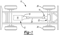
- an exemplary vehicle having an axle assembly (e.g., a rear axle assembly) constructed in accordance with the teachings of the present invention is generally indicated by reference numeral 10.
- the vehicle 10 can have a power train 12 and a drive line or drive train 14.
- the power train 12 can be conventionally constructed and can comprise a power source 16 and a transmission 18.
- the power source 16 can be configured to provide propulsive power and can comprise an internal combustion engine and/or an electric motor, for example.
- the transmission 18 can receive propulsive power from the power source 16 and can output power to the drive train 14.
- the transmission 18 can have a plurality of automatically or manually-selected gear ratios.
- the drive train 14 in the particular example provided is of a two-wheel, rear-wheel drive configuration, but those of skill in the art will appreciate that the teachings of the present invention are applicable to other drive train configurations, including four-wheel drive configurations, all-wheel drive configurations, and front-wheel drive configurations.
- the drive train 14 can include a prop shaft 20 and a rear axle assembly 22.
- the propshaft 20 can couple the transmission 18 to the rear axle assembly 22 such that rotary power output of the transmission 18 is received by the rear axle assembly 22.
- the rear axle assembly 22 can distribute the rotary power to the rear vehicle wheels 26.
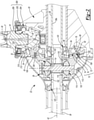
- the exemplary embodiment of the rear axle assembly 22 includes a housing assembly 30, an input pinion 32, a ring gear 34, a differential assembly 36, and a pair of axle shafts 38.
- the input pinion 32 can be rotatable about a first axis 40
- the ring gear 34 and the differential assembly 36 can be rotatable about a second axis 42 that can be transverse or perpendicular to the first axis 40.
- the housing assembly 30 can define a differential cavity 50 into which the differential assembly 36 can be received.
- the input pinion 32 can be received in the differential cavity 50 and can include a plurality of pinion teeth 52.
- the input pinion 32 can define an internal cavity 54 and a threaded aperture 56 that can intersect the internal cavity 54.
- a yoke flange YF can be received into the internal cavity 54 and a threaded fastener F can be received through the yoke flange YF and can be threaded into the threaded aperture 56 to secure the yoke flange YF to the input pinion 32.
- the ring gear 34 can be received in the differential cavity 50 and can include a plurality of ring gear teeth 60 that are meshingly engaged to the pinion teeth 52.
- the ring gear 34 can be a bevel gear (e.g., a spiral bevel gear, such as a hypoid gear).
- a ring gear bearing 70 supports the ring gear 34 for rotation relative to the housing assembly 30 about the second axis 42.
- the ring gear bearing 70 has an outer bearing race 72, an inner bearing race 74 and a plurality of first bearing elements 76.
- the outer bearing race 72 includes a first race member 78 and a second race member 80.
- the first race member 78 is unitarily and integrally formed with the ring gear 34, while the second race member 80 is received into a circumferentially extending groove 82 formed in the ring gear 34.
- the inner bearing race 74 of the ring gear bearing 70 is abutted against a shoulder 84 preferably formed on an annular projection or tube-like protrusion 88 of the housing assembly 30 that is positioned along the second axis 42 at a location that is between the first axis 40 and the first bearing elements 76.
- the inner bearing race 74 can be secured to the tube-like protrusion 88 in any desired manner, such as via a plurality of threaded fasteners (not shown).
- the tube-like protrusion 88 is threaded and is threadably engaged to a nut 90 that secures the inner bearing race 74 to the housing assembly 30.
- the first bearing elements are engaged to the inner bearing race 74 and the first and second race members 78 and 80 of the outer bearing race 72.
- the differential assembly 36 of the exemplarily embodiment of Figure 2 comprises a differential case 100, a pair of output members 102, and a means 104 for permitting speed differentiation between the output members 102.
- the differential case 100 is fixedly coupled to the ring gear 34 for rotation therewith and as such, conventional bearings for directly supporting the differential case 100 for rotation on the housing assembly 30 are not needed.
- the differential case 100 can secure the second race member 80 of the ring gear bearing 70 to the ring gear 34.
- a plurality of threaded fasteners 106 are received through a flange 108 formed on the differential case 100 and are threadably received into threaded holes formed in the ring gear 34.
- the second race member 80 When the threaded fasteners 106 are sufficiently tightened, the second race member 80 is engaged to both the flange 108 and the first bearing elements 76. In this condition, the second race member 80 may be spaced apart from the first race member 78 along the second axis 42 such that the first and second race members 78 and 80 are not in contact with one another.
- a shim (not shown) can be employed between the flange 108 and the second race member 80 to control the preloading of the ring gear bearing 70.
- the output members 102 can be rotatably disposed about the second axis 42.
- the speed differentiation means 104 can comprise any means for permitting speed differentiation between the output members 102.
- the speed differentiation means 104 can include one or more clutches, such as friction clutches (not shown), that can be operated to permit/control speed differentiation between the output members 102.
- the speed differentiation means 104 comprises a differential gearset 110 having a cross-pin 112, a pair of differential pinions 114 and a pair of side gears 116 that are co-formed with the output members 102.
- the cross-pin 112 can be mounted to the differential case 100 and can be disposed generally perpendicular to the second axis 42.
- the differential pinions 114 can be rotatably mounted on the cross-pin 112 and can be meshingly engaged with the side gears 116.
- the differential gearset 110 could be a planetary configuration that includes an internal gear (not shown), which is non-rotatably coupled to the differential case 100, a planet carrier (not shown), a sun gear (not shown) and a plurality of planet gears (not shown) that are journally supported on the planet carrier and meshingly engaged to the internal gear and the sun gear.
- Each of the output members 102 can be fixedly and non-rotatably coupled to an associated one of the side gears 116 (or to an associated one of the sun gear and the planet carrier if the differential gearset 110 employs the planetary configuration discussed above).
- Each of the output members 102 can comprise an internally splined structure that can be mounted on a corresponding one of the axle shafts 38.
- One of the axle shafts 38a can extend through the tub-like projection 88 formed on the housing assembly 30.
- An axle shaft bearing 120 can support the inner end of each axle shaft 38 for rotation on the housing assembly 30. Accordingly, it will be appreciated that the rear axle assembly 22 does not employ any bearings to directly support the differential case 100 for rotation on the housing assembly 30.
- the first thrust load is transmitted along a path that extends between the inner bearing race 74, the first bearing elements 76 and the first race member 78 (the first thrust load is not transmitted through the second race member 80), while the second thrust load is transmitted along a path that extends between the inner bearing race 74, the first bearing elements 76 and the second race member 80 (the second thrust load is not transmitted through the first race member 78).
- a pinion bearing 200 can support the input pinion 32 for rotation relative to the housing assembly 30 about the first axis 40.
- the pinion bearing 200 can have a plurality of second bearing elements 202 that are disposed circumferentially about the first axis 40.
- power transmission between the input pinon 32 and the ring gear 34 that drives the ring gear 34 about the second axis 42 in the first rotary direction generates a third thrust load that is directed along the first axis 40 in a third direction
- power transmission between the input pinion 32 and the ring gear 34 that drives the ring gear 34 about the second axis 42 in the second rotary direction opposite the first rotary direction generates a fourth thrust load that is directed along the first axis 40 in a fourth direction that is opposite the third direction.
- the third thrust load is transmitted through the second bearing elements 202 when the first thrust load is transmitted between the ring gear 34 and the housing assembly 30, and the fourth thrust load is transmitted through the second bearing elements 202 when the second thrust load is transmitted between the ring gear 34 and the housing assembly 30.
- the pinion bearing 200 is a four-point angular contact bearing
- the second bearing elements 202 are disposed in a single row
- the second bearing elements 202 have a spherical shape.
- the pinion bearing 200 can include a first pinion bearing race 204 and a second pinion bearing race 206.
- the first pinion bearing race 204 which can be an outer bearing race of the pinion bearing 200, can have first and second pinion race members 210 and 212, respectively.
- the first and second pinion race members 210 and 212 are configured such that the third thrust load is transmitted through the first pinion race member 210 but not the second pinion race member 212 and the fourth thrust load is transmitted through the second pinion race member 212 but not the first pinion race member 210.
- the second pinion bearing race 206 can be formed into a pinion body or shaft 220 of the input pinion 32.
- the second pinion bearing race 206 is a groove formed (i.e., machined) into the pinion body 220 of the input pinion 32 and as such, is unitarily and integrally formed with the input pinion 32.
Landscapes
- Engineering & Computer Science (AREA)
- General Engineering & Computer Science (AREA)
- Mechanical Engineering (AREA)
- Retarders (AREA)
- General Details Of Gearings (AREA)
Claims (17)
- Achsanordnung (22), Folgendes umfassend:eine Gehäuseanordnung (30),ein Antriebsritzel (32), das an die Gehäuseanordnung montiert ist, um sich um eine erste Achse (40) zu drehen,ein Kegelrad (34), das in der Gehäuseanordnung aufgenommen ist und mit dem Antriebsritzel in Zahneingriff steht,ein Kegelradlager (70), welches das Kegelrad zur Drehung relativ zur Gehäuseanordnung um eine zweite Achse (42) abstützt, wobei das Kegelradlager einen äußeren Lagerring (72), einen inneren Lagerring (74) und mehrere erste Lagerelemente (76) aufweist, wobei der innere Lagerring des Kegelradlagers an einer Schulter (84) anliegt, die an der Gehäuseanordnung gebildet und entlang der zweiten Achse an einer Stelle positioniert ist, die zwischen der ersten Achse und den ersten Lagerelementen liegt, undeine Differentialanordnung (36), die ein Differentialgehäuse (100) und ein Paar Ausgangselemente (102) aufweist,wobei die Kraftübertragung zwischen dem Antriebsritzel und dem Kegelrad, die das Kegelrad in einer ersten Drehrichtung um die zweite Achse antreibt, eine erste Axialkraft erzeugt, die entlang der zweiten Achse in eine erste Richtung gerichtet ist, wobei die Kraftübertragung zwischen dem Antriebsritzel und dem Kegelrad, die das Kegelrad um die zweite Achse in einer zweiten Drehrichtung antreibt, die der ersten Drehrichtung entgegengesetzt ist, eine zweite Axialkraft erzeugt, die entlang der zweiten Achse in eine zweite Richtung gerichtet ist, die der ersten Richtung entgegengesetzt ist, und wobei die erste und die zweite Axialkraft jeweils durch die ersten Lagerelemente übertragen werden, wenn die erste und die zweite Axialkraft zwischen dem Kegelrad und der Gehäuseanordnung übertragen werden,dadurch gekennzeichnet, dassder äußere Lagerring ein erstes Ringelement (78) und ein zweites Ringelement (80) umfasst,das erste Ringelement einheitlich und integral mit dem Kegelrad gebildet ist,das zweite Ringelement in einer sich umlaufend erstreckenden Ausnehmung (82) aufgenommen ist, die in dem Kegelrad gebildet ist,die ersten Lagerelemente mit dem inneren Lagerring und dem ersten und dem zweiten Ringelement des äußeren Lagerrings in Eingriff stehen unddas Differentialgehäuse fest mit dem Kegelrad gekoppelt ist, so dass das zweite Ringelement des äußeren Lagerrings entlang der zweiten Achse zwischen dem Differentialgehäuse und dem Kegelrad angeordnet ist.
- Achsanordnung nach Anspruch 1, wobei mehrere mit Gewinde versehene Befestigungsmittel das Kegelrad an dem Differentialgehäuse befestigen.
- Achsanordnung nach Anspruch 1, wobei die Differentialanordnung einen Differentialgetriebesatz (110) umfasst, der ein Paar Seitenräder (116) aufweist, und wobei jedes der Seitenräder zwecks gemeinsamer Drehung mit einem zugeordneten der Ausgangselemente gekoppelt ist.
- Achsanordnung nach Anspruch 3, wobei der Differentialgetriebesatz ferner mehrere Differentialritzel (114) umfasst, wobei jedes der Differentialritzel mit jedem der Seitenräder in Zahneingriff steht.
- Achsanordnung nach Anspruch 4, wobei jedes der Differentialritzel um eine entsprechende Ritzelachse drehbar ist, wobei die Ritzelachsen der Differentialritzel in einer gemeinsamen Ebene angeordnet sind und wobei die gemeinsame Ebene die zweite Achse an einer Stelle schneidet, die zwischen dem Kegelrad und der ersten Achse liegt.
- Achsanordnung nach Anspruch 1, wobei die ersten Lagerelemente eine Kugelform aufweisen.
- Achsanordnung nach Anspruch 1, wobei die ersten Lagerelemente in einer einzelnen Reihe angeordnet sind, die sich umlaufend um die zweite Achse erstreckt.
- Achsanordnung nach Anspruch 1, wobei das Antriebsritzel eine innere Öffnung (54) aufweist, in welcher ein Gabelflansch (YF) aufgenommen ist.
- Achsanordnung nach Anspruch 8, wobei in dem Antriebsritzel ein Loch (56) gebildet ist, wobei mindestens ein Teil des Lochs mit Gewinde versehen ist und wobei das Loch die innere Öffnung schneidet.
- Achsanordnung nach Anspruch 9, ferner ein mit Gewinde versehenes Befestigungsmittel (F) umfassend, das mittels Gewinde mit dem mit Gewinde versehenen Teil des Lochs gekoppelt ist, wobei das mit Gewinde versehene Befestigungsmittel den Gabelflansch mit dem Antriebsritzel koppelt.
- Achsanordnung nach Anspruch 1, ferner ein Ritzellager (200) umfassend, welches das Antriebsritzel zur Drehung relativ zur Gehäuseanordnung abstützt, wobei das Ritzellager mehrere zweite Lagerelemente (202) aufweist, die umlaufend um die erste Achse angeordnet sind, wobei die Kraftübertragung zwischen dem Antriebsritzel und dem Kegelrad, die das Kegelrad in der ersten Drehrichtung um die zweite Achse antreibt, eine dritte Axialkraft erzeugt, die entlang der ersten Achse in eine dritte Richtung gerichtet ist, wobei die Kraftübertragung zwischen dem Antriebsritzel und dem Kegelrad, die das Kegelrad um die zweite Achse in der zweiten Drehrichtung antreibt, die der ersten Drehrichtung entgegengesetzt ist, eine vierte Axialkraft erzeugt, die entlang der ersten Achse in eine vierte Richtung gerichtet ist, die der dritten Richtung entgegengesetzt ist, wobei die dritte Axialkraft durch die zweiten Lagerelemente übertragen wird, wenn die erste Axialkraft zwischen dem Kegelrad und der Gehäuseanordnung übertragen wird, und wobei die vierte Axialkraft durch die zweiten Lagerelemente übertragen wird, wenn die zweite Axialkraft zwischen dem Kegelrad und der Gehäuseanordnung übertragen wird.
- Achsanordnung nach Anspruch 11, wobei das Ritzellager einen ersten Ritzellagerring (204) umfasst, der ein erstes und ein zweites Ritzelringelement (210, 212) aufweist, wobei die dritte Axialkraft durch das erste Ritzelringelement, jedoch nicht durch das zweite Ritzelringelement übertragen wird und wobei die vierte Axialkraft durch das zweite Ritzelringelement, jedoch nicht durch das erste Ritzelringelement übertragen wird.
- Achsanordnung nach Anspruch 11, wobei der erste Ritzellagerring ein äußerer Lagerring des Ritzellagers ist.
- Achsanordnung nach Anspruch 11, wobei die zweiten Lagerelemente eine Kugelform aufweisen.
- Achsanordnung nach Anspruch 11, wobei die zweiten Lagerelemente in einer einzelnen Reihe angeordnet sind, die sich umlaufend um die erste Achse erstreckt.
- Achsanordnung nach Anspruch 11, wobei das Antriebsritzel ein Ritzelgehäuse (220) aufweist und wobei das Ritzellager einen Ritzellagerring (206) umfasst, der in das Ritzelgehäuse eingearbeitet ist, so dass der Ritzellagerring integral und einheitlich mit dem Antriebsritzel gebildet ist.
- Achsanordnung nach Anspruch 1, wobei die Gehäuseanordnung einer ringförmige Nabe (88) aufweist, wobei die Schulter an der ringförmigen Nabe gebildet ist und wobei eine der Achswellen in der ringförmigen Nabe aufgenommen ist.
Applications Claiming Priority (2)
| Application Number | Priority Date | Filing Date | Title |
|---|---|---|---|
| US15/427,348 US10113631B2 (en) | 2017-02-08 | 2017-02-08 | Axle assembly having ring gear with unitarily and integrally formed portion of a bearing race |
| PCT/US2018/014374 WO2018147992A1 (en) | 2017-02-08 | 2018-01-19 | Axle assembly having ring gear with unitarily and integrally formed portion of a bearing race |
Publications (3)
| Publication Number | Publication Date |
|---|---|
| EP3580477A1 EP3580477A1 (de) | 2019-12-18 |
| EP3580477A4 EP3580477A4 (de) | 2020-10-21 |
| EP3580477B1 true EP3580477B1 (de) | 2022-03-02 |
Family
ID=63037056
Family Applications (1)
| Application Number | Title | Priority Date | Filing Date |
|---|---|---|---|
| EP18751003.7A Active EP3580477B1 (de) | 2017-02-08 | 2018-01-19 | Achsenanordnung mit zahnkranz mit einheitlich und integral geformtem abschnitt eines lagerrings |
Country Status (4)
| Country | Link |
|---|---|
| US (2) | US10113631B2 (de) |
| EP (1) | EP3580477B1 (de) |
| CN (1) | CN110300864B (de) |
| WO (1) | WO2018147992A1 (de) |
Families Citing this family (2)
| Publication number | Priority date | Publication date | Assignee | Title |
|---|---|---|---|---|
| US11293534B2 (en) | 2019-12-02 | 2022-04-05 | American Axle & Manufacturing, Inc. | Electric drive module with transmission having parallel twin gear pairs sharing load to a final drive gear |
| US11319009B2 (en) | 2020-07-06 | 2022-05-03 | American Axle & Manufacturing, Inc. | Tooling system and method for assembling a vehicle driveline component |
Family Cites Families (37)
| Publication number | Priority date | Publication date | Assignee | Title |
|---|---|---|---|---|
| US783168A (en) | 1903-05-29 | 1905-02-21 | Walter C Baker | Power-transmission mechanism for automobiles. |
| US899891A (en) | 1906-04-18 | 1908-09-29 | Jules Niclausse | Axle for motor road-vehicles. |
| DE1255510B (de) | 1964-01-24 | 1967-11-30 | Porsche Kg | Anordnung des Ausgleichgetriebes und Lagerung der Wellen in einem Getriebegehaeuse aus Leichtmetall, insbesondere fuer Kraftfahrzeuge |
| US3385133A (en) | 1965-09-30 | 1968-05-28 | Honda Motor Co Ltd | Differential gear mechanism |
| US3792625A (en) | 1971-06-28 | 1974-02-19 | Skf Ind Trading & Dev | Pinion gear transmission |
| JPS6084472A (ja) | 1983-10-15 | 1985-05-13 | Isuzu Motors Ltd | 変速機などの歯車軸およびその製造方法 |
| US5203750A (en) | 1991-10-18 | 1993-04-20 | Dana Corporation | Angled vehicle axle assembly |
| JPH06117518A (ja) | 1992-09-30 | 1994-04-26 | Mitsubishi Motors Corp | 終減速装置のリダクションピニオン |
| JP3052037B2 (ja) | 1993-07-22 | 2000-06-12 | 本田技研工業株式会社 | スプライン結合構造 |
| JPH09290652A (ja) | 1996-04-25 | 1997-11-11 | Aisin Seiki Co Ltd | ディファレンシャル装置 |
| US6824489B2 (en) | 1998-08-29 | 2004-11-30 | Ina-Schaeffler Kg | Differential for a motor vehicle |
| JP4304771B2 (ja) | 1999-06-29 | 2009-07-29 | 日本精工株式会社 | 車輪支持用ハブユニット及びその組立方法 |
| US6544140B2 (en) | 2001-04-17 | 2003-04-08 | The Timken Company | Pinion mounting with direct tapered roller bearing arrangement |
| US7155824B2 (en) | 2001-08-15 | 2007-01-02 | American Axle & Manufacturing, Inc. | Method of manufacturing an automotive differential having an input pinion |
| US7314416B2 (en) | 2001-08-30 | 2008-01-01 | Gkn Walterscheid Gmbh | Drive shaft coupling |
| US20030070501A1 (en) | 2001-10-17 | 2003-04-17 | Bell Dale K. | Axle lubricant isolation |
| US6719661B2 (en) | 2001-10-25 | 2004-04-13 | Dana Corporation | Differential with pinion bearings supported on input yoke |
| US7086983B2 (en) | 2001-10-25 | 2006-08-08 | Dana Corporation | Differential with pinion bearings supported on input yoke |
| US6705965B2 (en) | 2002-03-29 | 2004-03-16 | Meritor Heavy Vehicle Technology, Llc | Carrier assembly for drive axle |
| US6863634B2 (en) | 2002-04-09 | 2005-03-08 | Dana Corporation | Tandem axle power divider assembly with inboard slip driveshaft connection |
| US6743138B2 (en) * | 2002-07-23 | 2004-06-01 | Visteon Global Technologies, Inc. | Compact differential housing assembly |
| US6849021B2 (en) | 2003-02-19 | 2005-02-01 | Visteon Global Technologies, Inc. | Limited slip differential |
| US7500934B2 (en) | 2003-11-06 | 2009-03-10 | Dana Heavy Vehicle Systems Group, Llc | Drive system and method of assembly thereof |
| US7188699B2 (en) | 2004-02-11 | 2007-03-13 | American Axle & Manufacturing, Inc. | Axle assembly with cooling pump |
| JP2006316984A (ja) | 2005-04-12 | 2006-11-24 | Kanzaki Kokyukoki Mfg Co Ltd | 双方向クラッチ |
| JP2007139014A (ja) | 2005-11-16 | 2007-06-07 | Nsk Ltd | アンギュラ玉軸受およびナット回転型ボールねじ装置 |
| US20100151983A1 (en) | 2008-12-11 | 2010-06-17 | Ziech James F | Spider-less vehicle differential |
| CN201334012Y (zh) | 2008-12-30 | 2009-10-28 | 中国汽车工程研究院有限公司 | 跨坐式单轨列车减速传动装置 |
| EP2422111B1 (de) | 2009-04-23 | 2013-10-16 | The Timken Company | Planetengetriebesystem mit halbintegrierten flexpin-anordnungen |
| US20110123264A1 (en) | 2009-11-25 | 2011-05-26 | Gm Global Technology Operations, Inc. | Conical Face Spline for Half-Shafts, Hub Bearings and the Like |
| US8616780B2 (en) | 2012-01-16 | 2013-12-31 | Arvinmeritor Technology, Llc | Bearing adjuster assembly |
| US9254713B2 (en) | 2013-03-15 | 2016-02-09 | American Axle & Manufacturing, Inc. | Axle assembly with inboard axle shaft bearings that support a differential mechanism |
| US9157515B2 (en) * | 2013-03-15 | 2015-10-13 | American Axle & Manufacturing, Inc. | Axle assembly |
| US9249872B2 (en) | 2013-03-15 | 2016-02-02 | American Axle & Manufacturing, Inc. | Axle assembly having an angular contact bearing that supports a ring gear for rotation on an axle housing |
| US9028358B2 (en) | 2013-03-15 | 2015-05-12 | American Axle & Manufacturing, Inc. | Disconnecting axle assembly |
| DE102014000430B4 (de) * | 2014-01-16 | 2017-07-13 | Audi Ag | Differenzialgetriebe |
| BR102015011976B1 (pt) * | 2014-06-03 | 2023-12-12 | American Axle & Manufacturing, Inc | Conjunto de eixo tendo um suporte de contato angular que suporta uma engrenagem de anel para girar em um alojamento do eixo |
-
2017
- 2017-02-08 US US15/427,348 patent/US10113631B2/en active Active
-
2018
- 2018-01-19 CN CN201880010668.0A patent/CN110300864B/zh active Active
- 2018-01-19 EP EP18751003.7A patent/EP3580477B1/de active Active
- 2018-01-19 WO PCT/US2018/014374 patent/WO2018147992A1/en not_active Ceased
- 2018-10-01 US US16/147,917 patent/US10487933B2/en active Active
Also Published As
| Publication number | Publication date |
|---|---|
| US20190032763A1 (en) | 2019-01-31 |
| CN110300864B (zh) | 2020-10-02 |
| BR112019016313A2 (pt) | 2020-03-31 |
| CN110300864A (zh) | 2019-10-01 |
| US10487933B2 (en) | 2019-11-26 |
| US10113631B2 (en) | 2018-10-30 |
| WO2018147992A1 (en) | 2018-08-16 |
| EP3580477A1 (de) | 2019-12-18 |
| EP3580477A4 (de) | 2020-10-21 |
| US20180223978A1 (en) | 2018-08-09 |
Similar Documents
| Publication | Publication Date | Title |
|---|---|---|
| US9500267B2 (en) | Drive module with compact differential mechanism | |
| US10557537B2 (en) | Axle assembly having a gear reduction unit and an interaxle differential unit | |
| US8998764B2 (en) | Drive module having planetary transmission with nested ring gears | |
| US10107375B2 (en) | Differential gear assembly | |
| EP3597467B1 (de) | Achsanordnung mit einer untersetzungseinheit und einer zwischenachsdifferenzialeinheit | |
| US20190111781A1 (en) | Axle Assembly Having a Gear Reduction Unit and an Interaxle Differential Unit | |
| EP2944848A1 (de) | Differentialanordnung mit Verbindungswelle | |
| EP3193044B1 (de) | Differentialanordnung mit stegwellenarretierung | |
| EP3805608B1 (de) | Achsanordnung mit differentialanordnung | |
| EP3608143B1 (de) | Antriebsachssystem mit einer planetenzwischenachsdifferentialeinheit | |
| US9249872B2 (en) | Axle assembly having an angular contact bearing that supports a ring gear for rotation on an axle housing | |
| JP2014503776A (ja) | 電気自動車用差動ギヤの直動駆動方式の駆動モジュール | |
| US9506549B2 (en) | Differential assembly | |
| EP3580477B1 (de) | Achsenanordnung mit zahnkranz mit einheitlich und integral geformtem abschnitt eines lagerrings | |
| GB2237851A (en) | Axle drive unit using unequal torque split bevel gear differential | |
| EP3408111B1 (de) | Trennbare achsanordnung mit einem planetendifferential | |
| EP3734116A1 (de) | Differentialanordnung mit überstehendem zahnkranz | |
| JP6510389B2 (ja) | 動力伝達装置およびその軸受の予圧調整方法 | |
| JP2010209989A (ja) | ドライブピニオン支持装置 |
Legal Events
| Date | Code | Title | Description |
|---|---|---|---|
| STAA | Information on the status of an ep patent application or granted ep patent |
Free format text: STATUS: THE INTERNATIONAL PUBLICATION HAS BEEN MADE |
|
| PUAI | Public reference made under article 153(3) epc to a published international application that has entered the european phase |
Free format text: ORIGINAL CODE: 0009012 |
|
| STAA | Information on the status of an ep patent application or granted ep patent |
Free format text: STATUS: REQUEST FOR EXAMINATION WAS MADE |
|
| 17P | Request for examination filed |
Effective date: 20190822 |
|
| AK | Designated contracting states |
Kind code of ref document: A1 Designated state(s): AL AT BE BG CH CY CZ DE DK EE ES FI FR GB GR HR HU IE IS IT LI LT LU LV MC MK MT NL NO PL PT RO RS SE SI SK SM TR |
|
| AX | Request for extension of the european patent |
Extension state: BA ME |
|
| DAV | Request for validation of the european patent (deleted) | ||
| DAX | Request for extension of the european patent (deleted) | ||
| A4 | Supplementary search report drawn up and despatched |
Effective date: 20200922 |
|
| RIC1 | Information provided on ipc code assigned before grant |
Ipc: F16H 48/40 20120101AFI20200916BHEP Ipc: F16H 48/42 20120101ALI20200916BHEP Ipc: F16H 48/08 20060101ALI20200916BHEP |
|
| GRAP | Despatch of communication of intention to grant a patent |
Free format text: ORIGINAL CODE: EPIDOSNIGR1 |
|
| STAA | Information on the status of an ep patent application or granted ep patent |
Free format text: STATUS: GRANT OF PATENT IS INTENDED |
|
| INTG | Intention to grant announced |
Effective date: 20210901 |
|
| GRAS | Grant fee paid |
Free format text: ORIGINAL CODE: EPIDOSNIGR3 |
|
| GRAA | (expected) grant |
Free format text: ORIGINAL CODE: 0009210 |
|
| STAA | Information on the status of an ep patent application or granted ep patent |
Free format text: STATUS: THE PATENT HAS BEEN GRANTED |
|
| AK | Designated contracting states |
Kind code of ref document: B1 Designated state(s): AL AT BE BG CH CY CZ DE DK EE ES FI FR GB GR HR HU IE IS IT LI LT LU LV MC MK MT NL NO PL PT RO RS SE SI SK SM TR |
|
| REG | Reference to a national code |
Ref country code: GB Ref legal event code: FG4D |
|
| REG | Reference to a national code |
Ref country code: CH Ref legal event code: EP Ref country code: AT Ref legal event code: REF Ref document number: 1472489 Country of ref document: AT Kind code of ref document: T Effective date: 20220315 |
|
| REG | Reference to a national code |
Ref country code: DE Ref legal event code: R096 Ref document number: 602018031643 Country of ref document: DE |
|
| REG | Reference to a national code |
Ref country code: IE Ref legal event code: FG4D |
|
| REG | Reference to a national code |
Ref country code: LT Ref legal event code: MG9D |
|
| REG | Reference to a national code |
Ref country code: NL Ref legal event code: MP Effective date: 20220302 |
|
| PG25 | Lapsed in a contracting state [announced via postgrant information from national office to epo] |
Ref country code: SE Free format text: LAPSE BECAUSE OF FAILURE TO SUBMIT A TRANSLATION OF THE DESCRIPTION OR TO PAY THE FEE WITHIN THE PRESCRIBED TIME-LIMIT Effective date: 20220302 Ref country code: RS Free format text: LAPSE BECAUSE OF FAILURE TO SUBMIT A TRANSLATION OF THE DESCRIPTION OR TO PAY THE FEE WITHIN THE PRESCRIBED TIME-LIMIT Effective date: 20220302 Ref country code: NO Free format text: LAPSE BECAUSE OF FAILURE TO SUBMIT A TRANSLATION OF THE DESCRIPTION OR TO PAY THE FEE WITHIN THE PRESCRIBED TIME-LIMIT Effective date: 20220602 Ref country code: LT Free format text: LAPSE BECAUSE OF FAILURE TO SUBMIT A TRANSLATION OF THE DESCRIPTION OR TO PAY THE FEE WITHIN THE PRESCRIBED TIME-LIMIT Effective date: 20220302 Ref country code: HR Free format text: LAPSE BECAUSE OF FAILURE TO SUBMIT A TRANSLATION OF THE DESCRIPTION OR TO PAY THE FEE WITHIN THE PRESCRIBED TIME-LIMIT Effective date: 20220302 Ref country code: ES Free format text: LAPSE BECAUSE OF FAILURE TO SUBMIT A TRANSLATION OF THE DESCRIPTION OR TO PAY THE FEE WITHIN THE PRESCRIBED TIME-LIMIT Effective date: 20220302 Ref country code: BG Free format text: LAPSE BECAUSE OF FAILURE TO SUBMIT A TRANSLATION OF THE DESCRIPTION OR TO PAY THE FEE WITHIN THE PRESCRIBED TIME-LIMIT Effective date: 20220602 |
|
| REG | Reference to a national code |
Ref country code: AT Ref legal event code: MK05 Ref document number: 1472489 Country of ref document: AT Kind code of ref document: T Effective date: 20220302 |
|
| PG25 | Lapsed in a contracting state [announced via postgrant information from national office to epo] |
Ref country code: PL Free format text: LAPSE BECAUSE OF FAILURE TO SUBMIT A TRANSLATION OF THE DESCRIPTION OR TO PAY THE FEE WITHIN THE PRESCRIBED TIME-LIMIT Effective date: 20220302 Ref country code: LV Free format text: LAPSE BECAUSE OF FAILURE TO SUBMIT A TRANSLATION OF THE DESCRIPTION OR TO PAY THE FEE WITHIN THE PRESCRIBED TIME-LIMIT Effective date: 20220302 Ref country code: GR Free format text: LAPSE BECAUSE OF FAILURE TO SUBMIT A TRANSLATION OF THE DESCRIPTION OR TO PAY THE FEE WITHIN THE PRESCRIBED TIME-LIMIT Effective date: 20220603 Ref country code: FI Free format text: LAPSE BECAUSE OF FAILURE TO SUBMIT A TRANSLATION OF THE DESCRIPTION OR TO PAY THE FEE WITHIN THE PRESCRIBED TIME-LIMIT Effective date: 20220302 |
|
| PG25 | Lapsed in a contracting state [announced via postgrant information from national office to epo] |
Ref country code: NL Free format text: LAPSE BECAUSE OF FAILURE TO SUBMIT A TRANSLATION OF THE DESCRIPTION OR TO PAY THE FEE WITHIN THE PRESCRIBED TIME-LIMIT Effective date: 20220302 |
|
| PG25 | Lapsed in a contracting state [announced via postgrant information from national office to epo] |
Ref country code: SM Free format text: LAPSE BECAUSE OF FAILURE TO SUBMIT A TRANSLATION OF THE DESCRIPTION OR TO PAY THE FEE WITHIN THE PRESCRIBED TIME-LIMIT Effective date: 20220302 Ref country code: SK Free format text: LAPSE BECAUSE OF FAILURE TO SUBMIT A TRANSLATION OF THE DESCRIPTION OR TO PAY THE FEE WITHIN THE PRESCRIBED TIME-LIMIT Effective date: 20220302 Ref country code: RO Free format text: LAPSE BECAUSE OF FAILURE TO SUBMIT A TRANSLATION OF THE DESCRIPTION OR TO PAY THE FEE WITHIN THE PRESCRIBED TIME-LIMIT Effective date: 20220302 Ref country code: PT Free format text: LAPSE BECAUSE OF FAILURE TO SUBMIT A TRANSLATION OF THE DESCRIPTION OR TO PAY THE FEE WITHIN THE PRESCRIBED TIME-LIMIT Effective date: 20220704 Ref country code: EE Free format text: LAPSE BECAUSE OF FAILURE TO SUBMIT A TRANSLATION OF THE DESCRIPTION OR TO PAY THE FEE WITHIN THE PRESCRIBED TIME-LIMIT Effective date: 20220302 Ref country code: CZ Free format text: LAPSE BECAUSE OF FAILURE TO SUBMIT A TRANSLATION OF THE DESCRIPTION OR TO PAY THE FEE WITHIN THE PRESCRIBED TIME-LIMIT Effective date: 20220302 Ref country code: AT Free format text: LAPSE BECAUSE OF FAILURE TO SUBMIT A TRANSLATION OF THE DESCRIPTION OR TO PAY THE FEE WITHIN THE PRESCRIBED TIME-LIMIT Effective date: 20220302 |
|
| PG25 | Lapsed in a contracting state [announced via postgrant information from national office to epo] |
Ref country code: IS Free format text: LAPSE BECAUSE OF FAILURE TO SUBMIT A TRANSLATION OF THE DESCRIPTION OR TO PAY THE FEE WITHIN THE PRESCRIBED TIME-LIMIT Effective date: 20220702 Ref country code: AL Free format text: LAPSE BECAUSE OF FAILURE TO SUBMIT A TRANSLATION OF THE DESCRIPTION OR TO PAY THE FEE WITHIN THE PRESCRIBED TIME-LIMIT Effective date: 20220302 |
|
| REG | Reference to a national code |
Ref country code: DE Ref legal event code: R097 Ref document number: 602018031643 Country of ref document: DE |
|
| PLBE | No opposition filed within time limit |
Free format text: ORIGINAL CODE: 0009261 |
|
| STAA | Information on the status of an ep patent application or granted ep patent |
Free format text: STATUS: NO OPPOSITION FILED WITHIN TIME LIMIT |
|
| PG25 | Lapsed in a contracting state [announced via postgrant information from national office to epo] |
Ref country code: DK Free format text: LAPSE BECAUSE OF FAILURE TO SUBMIT A TRANSLATION OF THE DESCRIPTION OR TO PAY THE FEE WITHIN THE PRESCRIBED TIME-LIMIT Effective date: 20220302 |
|
| 26N | No opposition filed |
Effective date: 20221205 |
|
| PG25 | Lapsed in a contracting state [announced via postgrant information from national office to epo] |
Ref country code: SI Free format text: LAPSE BECAUSE OF FAILURE TO SUBMIT A TRANSLATION OF THE DESCRIPTION OR TO PAY THE FEE WITHIN THE PRESCRIBED TIME-LIMIT Effective date: 20220302 |
|
| PG25 | Lapsed in a contracting state [announced via postgrant information from national office to epo] |
Ref country code: IT Free format text: LAPSE BECAUSE OF FAILURE TO SUBMIT A TRANSLATION OF THE DESCRIPTION OR TO PAY THE FEE WITHIN THE PRESCRIBED TIME-LIMIT Effective date: 20220302 |
|
| REG | Reference to a national code |
Ref country code: CH Ref legal event code: PL |
|
| PG25 | Lapsed in a contracting state [announced via postgrant information from national office to epo] |
Ref country code: LU Free format text: LAPSE BECAUSE OF NON-PAYMENT OF DUE FEES Effective date: 20230119 |
|
| REG | Reference to a national code |
Ref country code: BE Ref legal event code: MM Effective date: 20230131 |
|
| PG25 | Lapsed in a contracting state [announced via postgrant information from national office to epo] |
Ref country code: LI Free format text: LAPSE BECAUSE OF NON-PAYMENT OF DUE FEES Effective date: 20230131 Ref country code: CH Free format text: LAPSE BECAUSE OF NON-PAYMENT OF DUE FEES Effective date: 20230131 |
|
| PG25 | Lapsed in a contracting state [announced via postgrant information from national office to epo] |
Ref country code: BE Free format text: LAPSE BECAUSE OF NON-PAYMENT OF DUE FEES Effective date: 20230131 |
|
| PG25 | Lapsed in a contracting state [announced via postgrant information from national office to epo] |
Ref country code: IE Free format text: LAPSE BECAUSE OF NON-PAYMENT OF DUE FEES Effective date: 20230119 |
|
| PG25 | Lapsed in a contracting state [announced via postgrant information from national office to epo] |
Ref country code: MC Free format text: LAPSE BECAUSE OF FAILURE TO SUBMIT A TRANSLATION OF THE DESCRIPTION OR TO PAY THE FEE WITHIN THE PRESCRIBED TIME-LIMIT Effective date: 20220302 |
|
| PG25 | Lapsed in a contracting state [announced via postgrant information from national office to epo] |
Ref country code: MC Free format text: LAPSE BECAUSE OF FAILURE TO SUBMIT A TRANSLATION OF THE DESCRIPTION OR TO PAY THE FEE WITHIN THE PRESCRIBED TIME-LIMIT Effective date: 20220302 |
|
| PGFP | Annual fee paid to national office [announced via postgrant information from national office to epo] |
Ref country code: DE Payment date: 20250121 Year of fee payment: 8 |
|
| PGFP | Annual fee paid to national office [announced via postgrant information from national office to epo] |
Ref country code: FR Payment date: 20250127 Year of fee payment: 8 |
|
| PGFP | Annual fee paid to national office [announced via postgrant information from national office to epo] |
Ref country code: GB Payment date: 20250128 Year of fee payment: 8 |
|
| PG25 | Lapsed in a contracting state [announced via postgrant information from national office to epo] |
Ref country code: CY Free format text: LAPSE BECAUSE OF FAILURE TO SUBMIT A TRANSLATION OF THE DESCRIPTION OR TO PAY THE FEE WITHIN THE PRESCRIBED TIME-LIMIT; INVALID AB INITIO Effective date: 20180119 |
|
| PG25 | Lapsed in a contracting state [announced via postgrant information from national office to epo] |
Ref country code: HU Free format text: LAPSE BECAUSE OF FAILURE TO SUBMIT A TRANSLATION OF THE DESCRIPTION OR TO PAY THE FEE WITHIN THE PRESCRIBED TIME-LIMIT; INVALID AB INITIO Effective date: 20180119 |
|
| PG25 | Lapsed in a contracting state [announced via postgrant information from national office to epo] |
Ref country code: TR Free format text: LAPSE BECAUSE OF FAILURE TO SUBMIT A TRANSLATION OF THE DESCRIPTION OR TO PAY THE FEE WITHIN THE PRESCRIBED TIME-LIMIT Effective date: 20220302 |