US9028358B2 - Disconnecting axle assembly - Google Patents
Disconnecting axle assembly Download PDFInfo
- Publication number
- US9028358B2 US9028358B2 US14/447,775 US201414447775A US9028358B2 US 9028358 B2 US9028358 B2 US 9028358B2 US 201414447775 A US201414447775 A US 201414447775A US 9028358 B2 US9028358 B2 US 9028358B2
- Authority
- US
- United States
- Prior art keywords
- clutch
- assembly
- axle assembly
- axle
- differential
- Prior art date
- Legal status (The legal status is an assumption and is not a legal conclusion. Google has not performed a legal analysis and makes no representation as to the accuracy of the status listed.)
- Active
Links
Images


Classifications
-
- F—MECHANICAL ENGINEERING; LIGHTING; HEATING; WEAPONS; BLASTING
- F16—ENGINEERING ELEMENTS AND UNITS; GENERAL MEASURES FOR PRODUCING AND MAINTAINING EFFECTIVE FUNCTIONING OF MACHINES OR INSTALLATIONS; THERMAL INSULATION IN GENERAL
- F16H—GEARING
- F16H48/00—Differential gearings
- F16H48/20—Arrangements for suppressing or influencing the differential action, e.g. locking devices
- F16H48/22—Arrangements for suppressing or influencing the differential action, e.g. locking devices using friction clutches or brakes
-
- B—PERFORMING OPERATIONS; TRANSPORTING
- B60—VEHICLES IN GENERAL
- B60K—ARRANGEMENT OR MOUNTING OF PROPULSION UNITS OR OF TRANSMISSIONS IN VEHICLES; ARRANGEMENT OR MOUNTING OF PLURAL DIVERSE PRIME-MOVERS IN VEHICLES; AUXILIARY DRIVES FOR VEHICLES; INSTRUMENTATION OR DASHBOARDS FOR VEHICLES; ARRANGEMENTS IN CONNECTION WITH COOLING, AIR INTAKE, GAS EXHAUST OR FUEL SUPPLY OF PROPULSION UNITS IN VEHICLES
- B60K17/00—Arrangement or mounting of transmissions in vehicles
- B60K17/04—Arrangement or mounting of transmissions in vehicles characterised by arrangement, location or kind of gearing
- B60K17/16—Arrangement or mounting of transmissions in vehicles characterised by arrangement, location or kind of gearing of differential gearing
- B60K17/165—Arrangement or mounting of transmissions in vehicles characterised by arrangement, location or kind of gearing of differential gearing provided between independent half axles
-
- B—PERFORMING OPERATIONS; TRANSPORTING
- B60—VEHICLES IN GENERAL
- B60K—ARRANGEMENT OR MOUNTING OF PROPULSION UNITS OR OF TRANSMISSIONS IN VEHICLES; ARRANGEMENT OR MOUNTING OF PLURAL DIVERSE PRIME-MOVERS IN VEHICLES; AUXILIARY DRIVES FOR VEHICLES; INSTRUMENTATION OR DASHBOARDS FOR VEHICLES; ARRANGEMENTS IN CONNECTION WITH COOLING, AIR INTAKE, GAS EXHAUST OR FUEL SUPPLY OF PROPULSION UNITS IN VEHICLES
- B60K17/00—Arrangement or mounting of transmissions in vehicles
- B60K17/34—Arrangement or mounting of transmissions in vehicles for driving both front and rear wheels, e.g. four wheel drive vehicles
- B60K17/348—Arrangement or mounting of transmissions in vehicles for driving both front and rear wheels, e.g. four wheel drive vehicles having differential means for driving one set of wheels, e.g. the front, at one speed and the other set, e.g. the rear, at a different speed
- B60K17/35—Arrangement or mounting of transmissions in vehicles for driving both front and rear wheels, e.g. four wheel drive vehicles having differential means for driving one set of wheels, e.g. the front, at one speed and the other set, e.g. the rear, at a different speed including arrangements for suppressing or influencing the power transfer, e.g. viscous clutches
-
- B—PERFORMING OPERATIONS; TRANSPORTING
- B60—VEHICLES IN GENERAL
- B60K—ARRANGEMENT OR MOUNTING OF PROPULSION UNITS OR OF TRANSMISSIONS IN VEHICLES; ARRANGEMENT OR MOUNTING OF PLURAL DIVERSE PRIME-MOVERS IN VEHICLES; AUXILIARY DRIVES FOR VEHICLES; INSTRUMENTATION OR DASHBOARDS FOR VEHICLES; ARRANGEMENTS IN CONNECTION WITH COOLING, AIR INTAKE, GAS EXHAUST OR FUEL SUPPLY OF PROPULSION UNITS IN VEHICLES
- B60K23/00—Arrangement or mounting of control devices for vehicle transmissions, or parts thereof, not otherwise provided for
- B60K23/08—Arrangement or mounting of control devices for vehicle transmissions, or parts thereof, not otherwise provided for for changing number of driven wheels, for switching from driving one axle to driving two or more axles
-
- F—MECHANICAL ENGINEERING; LIGHTING; HEATING; WEAPONS; BLASTING
- F16—ENGINEERING ELEMENTS AND UNITS; GENERAL MEASURES FOR PRODUCING AND MAINTAINING EFFECTIVE FUNCTIONING OF MACHINES OR INSTALLATIONS; THERMAL INSULATION IN GENERAL
- F16H—GEARING
- F16H48/00—Differential gearings
- F16H48/06—Differential gearings with gears having orbital motion
- F16H48/08—Differential gearings with gears having orbital motion comprising bevel gears
- F16H2048/082—Differential gearings with gears having orbital motion comprising bevel gears characterised by the arrangement of output shafts
-
- F—MECHANICAL ENGINEERING; LIGHTING; HEATING; WEAPONS; BLASTING
- F16—ENGINEERING ELEMENTS AND UNITS; GENERAL MEASURES FOR PRODUCING AND MAINTAINING EFFECTIVE FUNCTIONING OF MACHINES OR INSTALLATIONS; THERMAL INSULATION IN GENERAL
- F16H—GEARING
- F16H48/00—Differential gearings
- F16H48/06—Differential gearings with gears having orbital motion
- F16H48/08—Differential gearings with gears having orbital motion comprising bevel gears
- F16H2048/087—Differential gearings with gears having orbital motion comprising bevel gears characterised by the pinion gears, e.g. their type or arrangement
-
- F—MECHANICAL ENGINEERING; LIGHTING; HEATING; WEAPONS; BLASTING
- F16—ENGINEERING ELEMENTS AND UNITS; GENERAL MEASURES FOR PRODUCING AND MAINTAINING EFFECTIVE FUNCTIONING OF MACHINES OR INSTALLATIONS; THERMAL INSULATION IN GENERAL
- F16H—GEARING
- F16H48/00—Differential gearings
- F16H48/06—Differential gearings with gears having orbital motion
- F16H48/10—Differential gearings with gears having orbital motion with orbital spur gears
- F16H48/11—Differential gearings with gears having orbital motion with orbital spur gears having intermeshing planet gears
Definitions
- the present disclosure relates to a disconnecting axle assembly.
- Disconnecting automotive axle assemblies typically include a differential mechanism having a differential case, which is supported by a pair of differential bearings for rotation within an axle housing, and a clutch that is configured to selectively interrupt the transmission of rotary power through the axle assembly.
- the differential bearings are typically mounted on trunnions formed on the differential case.
- the axle shafts of these axle assemblies have an inboard end that is typically engaged to an output member of the differential mechanism and supported indirectly by the differential case. While this type of arrangement is suited for its intended purpose, there remains a need in the art for an improved disconnecting axle assembly.
- the present teachings provide an axle assembly having an axle housing assembly, an input pinion, a ring gear, a differential assembly, a clutch, a spindle, and first and second output members.
- the axle housing assembly has a carrier housing and first and second end caps that are mounted to the carrier housing. The first end cap cooperates with the carrier housing to define a differential cavity, while the second end cap cooperates with the carrier housing to define a clutch cavity.
- the input pinion extends into the differential cavity.
- the ring gear is disposed in the differential cavity and is meshingly engaged with the input pinion.
- the ring gear is supported for rotation about a second axis by a four-point angular contact bearing.
- the differential assembly is received in the differential cavity and is configured to receive rotary power from the ring gear.
- the differential assembly has a first differential output and a second differential output.
- the clutch has a first clutch member and a second clutch member.
- the clutch is configured to selectively transmit rotary power between the first and second clutch members.
- the clutch is received in the clutch cavity.
- the spindle drivingly couples the first differential output with the first clutch member.
- the first output member is coupled for rotation with the first differential output.
- the second output member is coupled for rotation with the second clutch member.
- the spindle is received through a tubular portion of carrier housing.
- FIG. 1 is a longitudinal section view of an exemplary disconnecting axle assembly constructed in accordance with the teachings of the present disclosure
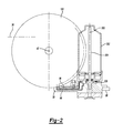
- FIG. 2 is a side elevation view of the axle assembly of FIG. 1 ;
- FIG. 3 is a longitudinal section view of a second exemplary disconnecting axle assembly constructed in accordance with the teachings of the present disclosure.
- an exemplary axle assembly constructed in accordance with the teachings of the present disclosure is generally indicated by reference numeral 10 .
- the axle assembly 10 can include an axle housing assembly 12 , an input pinion 14 , a ring gear 16 , a differential assembly 18 , a clutch 20 and first and second output members 22 and 24 , respectively.
- the input pinion 14 , the ring gear 16 , and associated portions of the axle housing assembly 12 can be configured as is described in co-pending U.S. patent application Ser. Nos. 14/205,535 and 14/294,221, the disclosures of which are incorporated by reference as if fully set forth in detail herein.
- the axle housing assembly 12 can include a carrier housing 30 .
- the input pinion 14 can be mounted on a tail bearing 32 and a head bearing 34 that can solely support the input pinion 14 for rotation relative to the carrier housing 30 about a first axis 36 .
- the tail bearing 32 can be a four-point angular contact bearing having an inner bearing race 38 that is unitarily and integrally formed into a shaft portion 40 of the input pinion 14 .
- the outer race 42 of the tail bearing 32 can be defined by a pair of race members 44 a and 44 b that can be spaced apart from one another along the first axis 36 .
- the head bearing 34 can be a type of roller bearing, such as a needle bearing, that can be mounted to a cylindrical projection 46 that is formed on the input pinion 14 .
- the head bearing 34 can be spaced apart from the tail bearing 32 so that a pinion gear 48 of the input pinion 14 is disposed between the tail and head bearings 32 and 34 .
- the ring gear 16 can be mounted on a four-point angular contact bearing 50 that can support the ring gear 16 for rotation relative to the carrier housing 30 about a second axis 52 .
- the four-point angular contact bearing 50 can have an outer bearing race 54 , which can be unitarily and integrally formed in the ring gear 16 , and an inner bearing race 56 that can be defined by first and second race members 58 a and 58 b .
- the first and second race members 58 a and 58 b can be spaced apart along the second axis 52 .
- the four-point angular contact bearing 50 that supports the ring gear 16 can be mounted on a generally tubular portion 60 on the carrier housing 30 , a nut 62 can be threaded onto the tubular portion 60 to preload the four-point angular contact bearing 50 , and the axle housing assembly 12 can further comprise first and second end caps 64 and 66 , respectively, that can be fixedly but removably coupled to the opposite axial ends of the carrier housing 30 .
- the first end cap 64 can cooperate with a first axial end of the carrier housing 30 to define a clutch cavity 70 into which portions of the clutch 20 can be received, while the second end cap 66 can cooperate with a second, opposite axial end of the carrier housing 30 to define a differential cavity 72 into which the differential assembly 18 can be received.
- the first and second end caps 64 and 66 can further define bearing mounts 74 a and 74 b , respectively, and seal mounts 76 a and 76 b , respectively.
- Bearings 78 can be mounted on the bearing mounts 74 a and 74 b and can be configured to support the first and second output members 22 and 24 , respectively, for rotation relative to the axle housing assembly 12 .
- Shaft seals 80 can be mounted on the seal mounts 76 a and 76 b and can be configured to form seals between the axle housing assembly 12 and the first and second output members 22 and 24 , respectively.
- the first and second end caps 64 and 66 can be sealingly engaged to the carrier housing 30 in any manner that is desired.
- each of the first and second end caps 64 and 66 has a joint face 84 that defines a groove 86 that receives a seal member 86 ; each of the joint faces 84 is abutted against a mating joint face 90 formed on the carrier housing 30 such that each of the seal members 86 sealingly engages a corresponding one of the joint faces 84 and a corresponding one of the mating joint face 90 .
- the carrier housing 30 can define a pump mount 96 that can define an intake conduit 96 and one or more output conduits 98 .
- the intake conduit 96 can be coupled in fluid communication with a sump 100 that is defined by the carrier housing 30 .
- the sump 100 can be configured to hold a lubricant that is used to lubricate and/or cool portions of the axle assembly 10 .
- the output conduit(s) 98 can be employed to transmit fluid to various portions of the axle assembly 10 , for example to lubricate and/or cool those portions and/or to operate the clutch 20 .
- the pump mount 96 can be located in any desired location, such as a location that is disposed on the carrier housing 30 across from the input pinion 14 .
- the differential assembly 18 is a planetary-type differential assembly having a ring gear 110 , a planet carrier 112 , a plurality of planet gears 114 and a sun gear 116 .
- the ring gear 110 can be fixedly coupled to the ring gear 16 for common rotation about the second axis 52 .
- the ring gear 110 is welded to the ring gear 16 , but it will be appreciated that other connection means, such as a toothed or spline connection, and/or a plurality of fasteners could be used in addition to or in lieu of a weld.
- the planet carrier 112 can comprise a carrier body and a plurality of pins 124 .
- the carrier body can comprise first and second carrier plates 126 and 128 , respectively, that can have a generally annular shape and can be spaced apart along the second axis 52 .
- the second carrier plate 128 can define a plurality of output spline teeth 130 .
- Each of the pins 124 can be fixedly coupled to the first and second carrier plates 126 and 128 .
- Each of the planet gears 114 can be journally supported on an associated one of the pins 124 and can be meshingly engaged with both the ring gear 110 and the sun gear 116 .
- the sun gear 116 can be fixedly coupled to a spindle 136 that can transmit rotary power between the sun gear 116 and the clutch 20 .
- the spindle 136 can be received through the ring gear 16 and a central bore 138 formed in the generally tubular portion 60 on the carrier housing 30 .
- the spindle 136 can be supported for rotation relative to the generally tubular portion 60 by a pair of bearings 140 , such as roller or needle bearings, that can be spaced apart from one another along the second axis 52 .
- bearings 140 such as roller or needle bearings, that can be spaced apart from one another along the second axis 52 .
- the sun gear 116 and the planet carrier 112 can be considered to be differential outputs of the differential assembly 18 .
- the clutch 20 can be any type of clutch that is configured to selectively transmit rotary power between the differential assembly 18 and the first output member 22 .
- the clutch 20 is a friction clutch that comprises a first clutch portion 150 , a second clutch portion 152 , a clutch pack 154 , and an actuator 156 .
- the first clutch portion 150 can be coupled to an end of the spindle 136 that is opposite the sun gear 116 .
- the first clutch portion 150 can include a first coupling portion 160 , a second coupling portion 162 , and a first radially extending portion 164 that extends in a radial direction between the first and second coupling portions 160 and 162 .
- the first coupling portion 160 can comprise a plurality of spline teeth 166 that can be meshingly engaged to a plurality of mating spline teeth 168 that are formed on the spindle 136 .
- the first radially extending portion 164 can be integrally and unitarily formed with the first coupling portion and can define a first annular shoulder 170 against which an annular thrust bearing 172 can be located.
- the annular thrust bearing 172 can be disposed between the first radially extending portion 164 and an annular surface 176 that is formed on an end face 178 of the carrier housing 30 .
- the second coupling portion 162 is a discrete component that is fixedly coupled (e.g., welded) to the first radially extending portion 164 .
- the second coupling portion 162 can include an annular body member 182 , which can be located on a second annular shoulder 184 formed on the first radially extending portion 164 , and a circumferentially extending flange 186 .
- the circumferentially extending flange 186 can define a plurality of first clutch teeth 188 .
- the second clutch portion 152 can comprise a third coupling portion 190 , a fourth coupling portion 192 and a second radially extending portion 194 that extends in a radial direction between the third and fourth coupling portions 190 and 192 .
- the third coupling portion 190 can include a circumferentially extending flange that can define a plurality of second clutch teeth 200 .
- the fourth coupling portion 192 can comprise a plurality of spline teeth 202 .
- one or more apertures 206 can be formed through the first radially extending portion 164 and/or the second radially extending portion 194 and/or the circumferentially extending flange of the third coupling portion 190 to facilitate the transmission of a lubricating and/or cooling fluid through the clutch 20 .
- the clutch pack 154 can comprise a plurality of first clutch plates 220 that are interleaved with a plurality of second clutch plates 222 .
- the first clutch plates 220 can be rotatably coupled to the first clutch portion 150 in any desired manner.
- the second clutch plates 222 can be rotatably coupled to the second clutch portion 152 in any desired manner.
- the first and second clutch plates 220 and 222 have outer and inner spline teeth that matingly engage the first and second clutch teeth 188 and 200 , respectively.
- the actuator 156 can comprise an apply plate 230 , a thrust bearing 232 , a cylinder assembly 234 , one or more springs 236 for biasing the apply plate 230 in a predetermined return direction, and a fluid pump 238 .
- the apply plate 230 can be an annular structure that can be non-rotatably but axially slidably coupled to the second clutch portion 152 and can include an apply portion 250 , an annular shoulder 252 and one or more reaction members 254 .
- the apply portion 250 includes a plurality of apertures that are slidably received on the second clutch teeth 200 such that the apply portion 250 is slidably disposed on the third coupling portion 190 .
- the apply portion 250 is configured to abut the clutch pack 154 .
- the reaction member(s) 254 can extend radially inwardly from the third coupling portion 190 and the one or more springs 236 , which can comprise a plurality of helical coil compression springs, can be received between the second radially extending portion 194 and the reaction member(s) 254 to bias the apply plate 230 in an axial direction along the second axis 52 away from the second radially extending portion 194 .
- the annular shoulder 252 can be disposed on a side of the apply plate 230 that is opposite the clutch pack 154 .
- the thrust bearing 232 can be located or received on the annular shoulder 252 .
- the cylinder assembly 234 can comprise a cylinder 260 and a piston 262 .
- the cylinder 260 can be defined by an annular cavity 264 formed in the first end cap 64 .
- the piston 262 can comprise an annular structure 266 and a pair of seals 268 a and 268 b that are mounted to the outside diametrical surface and the inside diametrical surface of the annular structure 266 to form respective seals between the annular structure 266 and the outer and inner cylinder walls 270 and 272 , respectively.
- the fluid pump 238 can be any type of pump, such as a gerotor pump, and can be mounted to the pump mount 96 on the carrier housing 30 .
- the fluid pump 238 can be configured to intake fluid from the sump 100 via the intake conduit 96 and to output pressurized fluid to the output conduit(s) 98 to provide fluid to desired areas of the axle assembly 10 .
- one or more of the output conduits 98 could be configured to provide fluid to selected areas of the axle assembly 10 so that the fluid lubricates and/or cools a desired area.
- At least one output conduit 98 is configured to supply pressurized fluid to the cylinder assembly 234 (i.e., when the fluid pump 238 is operated) to drive the piston 262 in a predetermined apply direction that can be opposite the predetermined return direction.
- movement of the piston 262 in the predetermined apply direction causes corresponding movement of the apply plate 230 along the second axis 52 toward the second radially extending portion 194 of the second clutch portion 152 to thereby compress the clutch pack 154 so that rotary power can be transmitted through the clutch 20 .
- a biasing force produced by the at least one spring 236 and applied to the apply plate 230 can be configured to drive the apply plate 230 and the piston 262 in the predetermined return direction when pressurized fluid is not supplied by the fluid pump 238 and fluid pressure in a volume between the piston 262 and the cylinder 260 has dropped below a predetermined fluid pressure.
- the drop in fluid pressure in the volume between the piston 262 and the cylinder 260 can be a result of the opening of a control valve (not shown) to vent fluid from the volume, leakage of fluid from the volume, and/or reversal of the fluid pump 238 to withdraw fluid from the volume via the at least one output conduit 98 .
- the pump mount 96 can be configured to orient a rotational element of a fluid pump 238 , such as an inner rotor of a gerotor pump, along a pump axis 300 that is transverse (e.g., orthogonal) to the first and second axes 36 and 52 .
- the fluid pump 238 is driven by an electric motor 302 having an output shaft 304 that is oriented coincidently with the pump axis 300 . Configuration in this manner may be desirable in some instances because the fluid pump 238 and the electric motor 302 are shrouded in part by portions of the axle housing assembly 12 , including the carrier housing 30 .
- the first and second output members 22 and 24 can be generally similar in their construction.
- the first output member 22 can be a shaft-like structure having a plurality of spline teeth 320 , a mating bearing mount 322 , a seal surface 324 and a second bearing mount 326 .
- the spline teeth 320 can be matingly engaged to the spline teeth 202 of the fourth coupling portion 192 on the second clutch portion 152 .
- Engagement of the spline teeth 320 of the first output member 22 with the spline teeth 202 of the fourth coupling portion 192 can couple the second clutch portion 152 and the first output member 22 to one another for common rotation about the second axis 52 .
- the mating bearing mount 322 can receive the bearing 78 that is disposed between the first output member 22 and the first end cap 64 to support the first output member 22 for rotation relative to the first end cap 64 about the second axis 52 .
- the bearing 78 can be disposed between a shoulder 330 , which can separate the mating bearing mount 322 and the seal surface 324 , and a first retaining element 332 , such as an external snap ring, that can be axially coupled to the first output member 22 .
- the seal surface 324 can be a circumferentially extending surface against which one or more seal elements (e.g., seal lips) of the seal 80 can be sealingly engaged.
- a second retaining element 336 such as an external snap ring, can be axially coupled to the spline teeth 320 of the first output member 22 to limit movement of the first output member 22 along the second axis 52 in a direction away from the carrier housing 30 .
- a bearing 340 can be disposed between the spindle 136 and the second bearing mount 326 to further and directly support the first output member 22 for rotation relative to the first end cap 64 about the second axis 52 .
- the bearing 340 is a type of roller bearing, such as a needle bearing, but those of ordinary skill in the art will appreciate that the bearing 340 could be configured differently.
- the second bearing mount 326 can be reduced in diameter relative to the first bearing mount 322 to aid in reducing the size of various components of the axle assembly 10 , including the bearing 340 and the spindle 136 .
- Shoulders 350 and 352 can be formed on the first output member 22 and the spindle 136 to limit relative axial movement of the bearing 340 .
- the second output member 24 can be a shaft-like structure having a plurality of spline teeth 420 , a mating bearing mount 422 , a seal surface 424 and a second bearing mount 426 .
- the spline teeth 420 of the second output member 24 can be matingly engaged to the spline teeth 130 of the planet carrier 112 of the differential assembly 18 . Engagement of the spline teeth 420 of the second output member 24 with the spline teeth 130 of the planet carrier 112 can couple the planet carrier 112 and the second output member 24 to one another for common rotation about the second axis 52 .
- the mating bearing mount 422 can receive the bearing 78 that is disposed between the second output member 24 and the second end cap 66 to support the second output member 24 for rotation relative to the second end cap 66 about the second axis 52 .
- the bearing 78 can be disposed between a shoulder 430 , which can separate the mating bearing mount 422 and the seal surface 424 , and a first retaining element 432 , such as an external snap ring, that can be axially coupled to the second output member 24 .
- the seal surface 424 can be a circumferentially extending surface against which one or more seal elements (e.g., seal lips) of the seal 80 can be sealingly engaged.
- a second retaining element 436 such as an external snap ring, can be axially coupled to the spline teeth 420 of the second output member 24 to limit movement of the second output member 24 along the second axis 52 in a direction away from the carrier housing 30 .
- a bearing 440 can be disposed between the spindle 136 and the second bearing mount 426 to further support the first output member 22 for rotation about the second axis 52 .
- the bearing 440 is a type of roller bearing, such as a needle bearing, but those of ordinary skill in the art will appreciate that the bearing 440 could be configured differently.
- the second bearing mount 426 can be reduced in diameter relative to the first bearing mount 424 to aid in reducing the size of various components of the axle assembly 10 , including the bearing 440 and the spindle 136 .
- Shoulders 450 and 452 can be formed on the second output member 24 and the spindle 136 to limit relative axial movement of the bearing 440 .
- a second axle assembly constructed in accordance with the teachings of the present disclosure is generally indicated by reference numeral 10 ′.
- the axle assembly 10 ′ is generally similar to the axle assembly 10 of FIG. 1 , except that the clutch 20 ′ and its integration into the axle housing assembly 12 ′ have been mirrored along the second axis 52 .
- the cylinder 260 ′ associated with the actuator 156 ′ can be defined by the carrier housing 30 ′, the spline teeth 202 of the fourth coupling portion 192 ′ can be meshingly engaged with the spline teeth 168 of the spindle 136 , the spline teeth 168 of the first coupling portion 160 ′ can be meshingly engaged with the spline teeth 320 of the first output member 22 and the annular thrust bearing 172 can be disposed between the first radially extending portion 164 and an annular surface 176 ′ that is formed on an end face of the first end cap 64 ′.
- first and second end caps 64 ′ and 66 ′ can be changed to modify the manner in which the first and second end caps 64 ′ and 66 ′ are sealed and fixedly coupled to the carrier housing 30 ′.
- each of the first and second end caps 64 ′ and 66 ′ defines a seal shoulder 500 on which an O-ring type seal 502 is mounted.
- Each seal shoulder 500 is matingly received into an associated bore 506 in an axial end of the carrier housing 30 ′ that defines a corresponding mating seal shoulder 508 so that the O-ring type seal 502 is sealingly engaged to outer and inner circumferentially extending walls 510 and 512 , respectively, formed on the carrier housing 30 ′ and one of the first and second end caps 64 ′ and 66 ′ and is disposed axially between shoulder walls 514 and 516 formed on the carrier housing 30 ′ and one of the first and second end caps 64 ′ and 66 ′.
- a securing member 520 such as an internal snap ring, can be received into a groove 522 formed in the bore 506 that defines the mating seal shoulder 524 and can be abutted against an outboard lateral side of the first and second end caps 64 ′ and 66 ′.
Landscapes
- Engineering & Computer Science (AREA)
- Mechanical Engineering (AREA)
- General Engineering & Computer Science (AREA)
- Chemical & Material Sciences (AREA)
- Combustion & Propulsion (AREA)
- Transportation (AREA)
- Retarders (AREA)
Abstract
Description
Claims (20)
Priority Applications (4)
| Application Number | Priority Date | Filing Date | Title |
|---|---|---|---|
| US14/447,775 US9028358B2 (en) | 2013-03-15 | 2014-07-31 | Disconnecting axle assembly |
| CN201510324618.8A CN105317965B (en) | 2014-07-31 | 2015-06-12 | Disconnect shaft assembly |
| BR102015014033-9A BR102015014033B1 (en) | 2014-07-31 | 2015-06-15 | Shaft set disconnect |
| DE102015112356.8A DE102015112356B4 (en) | 2014-07-31 | 2015-07-29 | Axle assembly with separating coupling |
Applications Claiming Priority (3)
| Application Number | Priority Date | Filing Date | Title |
|---|---|---|---|
| US201361787547P | 2013-03-15 | 2013-03-15 | |
| US14/205,535 US9157515B2 (en) | 2013-03-15 | 2014-03-12 | Axle assembly |
| US14/447,775 US9028358B2 (en) | 2013-03-15 | 2014-07-31 | Disconnecting axle assembly |
Related Parent Applications (1)
| Application Number | Title | Priority Date | Filing Date |
|---|---|---|---|
| US14/205,535 Continuation-In-Part US9157515B2 (en) | 2013-03-15 | 2014-03-12 | Axle assembly |
Publications (2)
| Publication Number | Publication Date |
|---|---|
| US20140342866A1 US20140342866A1 (en) | 2014-11-20 |
| US9028358B2 true US9028358B2 (en) | 2015-05-12 |
Family
ID=51896217
Family Applications (1)
| Application Number | Title | Priority Date | Filing Date |
|---|---|---|---|
| US14/447,775 Active US9028358B2 (en) | 2013-03-15 | 2014-07-31 | Disconnecting axle assembly |
Country Status (1)
| Country | Link |
|---|---|
| US (1) | US9028358B2 (en) |
Cited By (11)
| Publication number | Priority date | Publication date | Assignee | Title |
|---|---|---|---|---|
| WO2017091714A1 (en) | 2015-11-25 | 2017-06-01 | American Axle & Manufacturing, Inc. | Axle assembly |
| US10012299B2 (en) | 2015-10-14 | 2018-07-03 | Dana Automotive Systems Group, Llc | Integrated active limited slip differential |
| US10113631B2 (en) | 2017-02-08 | 2018-10-30 | American Axle & Manufacturing, Inc. | Axle assembly having ring gear with unitarily and integrally formed portion of a bearing race |
| US10179477B2 (en) * | 2016-07-08 | 2019-01-15 | Arvinmeritor Technology, Llc | Axle assembly having a support bearing assembly |
| US10487889B2 (en) | 2016-03-25 | 2019-11-26 | American Axle & Manufacturing, Inc. | Disconnecting axle assembly |
| US10710454B2 (en) | 2016-01-26 | 2020-07-14 | American Axle & Manufacturing, Inc. | Disconnectable axle assembly having a planetary differential |
| US10955043B2 (en) | 2019-08-19 | 2021-03-23 | Dana Heavy Vehicle Group, LLC | Axle assembly with variable speed pump |
| DE112016003291B4 (en) * | 2015-07-21 | 2021-06-10 | American Axle & Manufacturing, Inc. | Powertrain actuator powered by a synchronization event |
| US11047470B2 (en) | 2019-03-26 | 2021-06-29 | Dana Heavy Vehicle Systems Group, Llc | Axle assembly with lubrication pump |
| US11156281B2 (en) | 2019-02-01 | 2021-10-26 | Dana Heavy Vehicle Systems Group, Llc | Axle assembly with lubrication pump |
| US11525490B1 (en) | 2022-03-04 | 2022-12-13 | American Axle & Manufacturing, Inc. | Power transmission device having a friction clutch and a controller configured to determine an approximated temperature of the friction clutch and responsively control the friction clutch |
Families Citing this family (9)
| Publication number | Priority date | Publication date | Assignee | Title |
|---|---|---|---|---|
| US9103427B2 (en) * | 2013-03-15 | 2015-08-11 | American Axle & Manufacturing, Inc. | Axle assembly |
| US9157515B2 (en) | 2013-03-15 | 2015-10-13 | American Axle & Manufacturing, Inc. | Axle assembly |
| US9902263B2 (en) * | 2015-11-24 | 2018-02-27 | American Axle & Manufacturing, Inc. | Multi-plate friction clutch having center lubricant feed and lubricant evacuation capabilities |
| CN108463653B (en) * | 2016-01-26 | 2021-06-22 | 美国轮轴制造公司 | Planetary unit with planet carrier with pins fixed and non-rotatably mounted to the carrier body |
| EP3225423A1 (en) * | 2016-03-29 | 2017-10-04 | Meritor Heavy Vehicle Systems Cameri SpA | Axle assembly |
| US20190063576A1 (en) * | 2017-08-25 | 2019-02-28 | American Axle & Manufacturing, Inc. | Disconnecting axle assembly including an asymmetrically geared differential |
| DE112019003008T5 (en) * | 2018-06-14 | 2021-03-04 | American Axle & Manufacturing, Inc. | Hybrid axle assembly with external rotor motor and ring gear mounted directly on an axle housing |
| US10704663B2 (en) | 2018-09-06 | 2020-07-07 | American Axle & Manufacturing, Inc. | Modular disconnecting drive module with torque vectoring augmentation |
| US10927937B2 (en) | 2018-09-06 | 2021-02-23 | American Axle & Manufacturing, Inc. | Modular disconnecting drive module with torque vectoring augmentation |
Citations (29)
| Publication number | Priority date | Publication date | Assignee | Title |
|---|---|---|---|---|
| US696704A (en) | 1900-08-04 | 1902-04-01 | L B Hogue | Driving-gear. |
| US1987716A (en) | 1933-09-25 | 1935-01-15 | Chrysler Corp | Torque transmitting apparatus |
| US3344687A (en) | 1965-10-22 | 1967-10-03 | Ford Motor Co | Axle subassembly |
| US4182201A (en) | 1977-08-01 | 1980-01-08 | Fmc Corporation | Differential with floating pinion pin |
| US5098355A (en) | 1990-12-05 | 1992-03-24 | Eaton Corporation | Floating ring gear and differential gear assembly |
| US6056663A (en) | 1999-04-30 | 2000-05-02 | Dana Corporation | Short span differential gear assembly |
| JP2001010304A (en) | 1999-06-29 | 2001-01-16 | Nsk Ltd | Hub unit for supporting wheels and method of assembling the same |
| US6540634B2 (en) | 2000-10-25 | 2003-04-01 | Dana Corporation | Wheel differential shift mechanism |
| US20030070501A1 (en) | 2001-10-17 | 2003-04-17 | Bell Dale K. | Axle lubricant isolation |
| US6616565B1 (en) | 2002-03-19 | 2003-09-09 | Yao-Yu Chen | Differential gear designed for use in light-duty motor vehicles |
| US6623396B2 (en) | 2002-01-31 | 2003-09-23 | Visteon Global Technologies, Inc. | Differential gear assembly |
| EP1348589A2 (en) | 2002-03-29 | 2003-10-01 | ArvinMeritor Technology, LLC | A carrier assembly for a drive axle |
| US6645113B2 (en) | 2001-09-28 | 2003-11-11 | Visteon Global Technologies, Inc. | Differential gear retention system |
| US6652408B2 (en) | 2001-12-11 | 2003-11-25 | Visteon Global Technologies, Inc. | Vehicular differential with ring gear directly loading the differential pin |
| US6695739B2 (en) | 2002-06-25 | 2004-02-24 | Torque-Traction Technologies, Inc. | Ultra narrow adjustable differential assembly |
| US6699154B2 (en) | 2002-01-31 | 2004-03-02 | Visteon Global Technologies, Inc. | Differential gear assembly |
| US6702707B2 (en) | 2002-01-31 | 2004-03-09 | Visteon Global Technologies, Inc. | Differential assembly |
| US7022041B2 (en) | 2004-03-05 | 2006-04-04 | American Axle & Manufacturing, Inc. | Helical gear differential |
| US7188699B2 (en) | 2004-02-11 | 2007-03-13 | American Axle & Manufacturing, Inc. | Axle assembly with cooling pump |
| US7393301B2 (en) | 2005-08-05 | 2008-07-01 | Dana Heavy Vehicle Systems Group, Llc | Gear driven direct differential cross |
| US7520833B2 (en) * | 2005-07-08 | 2009-04-21 | Honda Motor Co., Ltd. | Vehicular driving force distribution system |
| US20090163313A1 (en) * | 2005-12-20 | 2009-06-25 | Gkn Driveline International Gmbh | Differential assembly with two jointly actuated axial adjustment devices |
| US7775928B2 (en) | 2007-09-21 | 2010-08-17 | American Axle & Manufacturing, Inc. | Differential and bearing arrangement |
| WO2010123964A1 (en) | 2009-04-23 | 2010-10-28 | The Timken Company | Epicyclic gear system with semi-integrated flexpin assemblies |
| US7901318B2 (en) | 2007-09-27 | 2011-03-08 | American Axle & Manufacturing, Inc. | Four pinion differential with cross pin retention unit and related method |
| US7984782B2 (en) | 2007-09-27 | 2011-07-26 | American Axle & Manufacturing, Inc. | Motorcycle axle assembly |
| US8167758B2 (en) | 2008-12-08 | 2012-05-01 | American Axle & Manufacturing, Inc. | Drive axle assembly with gear mesh lubrication systems for lubricating gear mesh and/or differential bearings |
| US20130303323A1 (en) * | 2012-05-14 | 2013-11-14 | American Axle & Manufacturing, Inc. | Power transmitting component |
| US8951159B2 (en) * | 2012-10-10 | 2015-02-10 | Eaton Corporation | Differential case having lock pins in-line with clutch ear guides |
-
2014
- 2014-07-31 US US14/447,775 patent/US9028358B2/en active Active
Patent Citations (30)
| Publication number | Priority date | Publication date | Assignee | Title |
|---|---|---|---|---|
| US696704A (en) | 1900-08-04 | 1902-04-01 | L B Hogue | Driving-gear. |
| US1987716A (en) | 1933-09-25 | 1935-01-15 | Chrysler Corp | Torque transmitting apparatus |
| US3344687A (en) | 1965-10-22 | 1967-10-03 | Ford Motor Co | Axle subassembly |
| US4182201A (en) | 1977-08-01 | 1980-01-08 | Fmc Corporation | Differential with floating pinion pin |
| US5098355A (en) | 1990-12-05 | 1992-03-24 | Eaton Corporation | Floating ring gear and differential gear assembly |
| US6056663A (en) | 1999-04-30 | 2000-05-02 | Dana Corporation | Short span differential gear assembly |
| JP2001010304A (en) | 1999-06-29 | 2001-01-16 | Nsk Ltd | Hub unit for supporting wheels and method of assembling the same |
| US6540634B2 (en) | 2000-10-25 | 2003-04-01 | Dana Corporation | Wheel differential shift mechanism |
| US6645113B2 (en) | 2001-09-28 | 2003-11-11 | Visteon Global Technologies, Inc. | Differential gear retention system |
| US20030070501A1 (en) | 2001-10-17 | 2003-04-17 | Bell Dale K. | Axle lubricant isolation |
| US6652408B2 (en) | 2001-12-11 | 2003-11-25 | Visteon Global Technologies, Inc. | Vehicular differential with ring gear directly loading the differential pin |
| US6623396B2 (en) | 2002-01-31 | 2003-09-23 | Visteon Global Technologies, Inc. | Differential gear assembly |
| US6702707B2 (en) | 2002-01-31 | 2004-03-09 | Visteon Global Technologies, Inc. | Differential assembly |
| US6699154B2 (en) | 2002-01-31 | 2004-03-02 | Visteon Global Technologies, Inc. | Differential gear assembly |
| US6616565B1 (en) | 2002-03-19 | 2003-09-09 | Yao-Yu Chen | Differential gear designed for use in light-duty motor vehicles |
| EP1348589A2 (en) | 2002-03-29 | 2003-10-01 | ArvinMeritor Technology, LLC | A carrier assembly for a drive axle |
| US6695739B2 (en) | 2002-06-25 | 2004-02-24 | Torque-Traction Technologies, Inc. | Ultra narrow adjustable differential assembly |
| US7188699B2 (en) | 2004-02-11 | 2007-03-13 | American Axle & Manufacturing, Inc. | Axle assembly with cooling pump |
| US7022041B2 (en) | 2004-03-05 | 2006-04-04 | American Axle & Manufacturing, Inc. | Helical gear differential |
| US7232399B2 (en) | 2004-03-05 | 2007-06-19 | American Axle & Manufacturing, Inc. | Differential assembly |
| US7520833B2 (en) * | 2005-07-08 | 2009-04-21 | Honda Motor Co., Ltd. | Vehicular driving force distribution system |
| US7393301B2 (en) | 2005-08-05 | 2008-07-01 | Dana Heavy Vehicle Systems Group, Llc | Gear driven direct differential cross |
| US20090163313A1 (en) * | 2005-12-20 | 2009-06-25 | Gkn Driveline International Gmbh | Differential assembly with two jointly actuated axial adjustment devices |
| US7775928B2 (en) | 2007-09-21 | 2010-08-17 | American Axle & Manufacturing, Inc. | Differential and bearing arrangement |
| US7901318B2 (en) | 2007-09-27 | 2011-03-08 | American Axle & Manufacturing, Inc. | Four pinion differential with cross pin retention unit and related method |
| US7984782B2 (en) | 2007-09-27 | 2011-07-26 | American Axle & Manufacturing, Inc. | Motorcycle axle assembly |
| US8167758B2 (en) | 2008-12-08 | 2012-05-01 | American Axle & Manufacturing, Inc. | Drive axle assembly with gear mesh lubrication systems for lubricating gear mesh and/or differential bearings |
| WO2010123964A1 (en) | 2009-04-23 | 2010-10-28 | The Timken Company | Epicyclic gear system with semi-integrated flexpin assemblies |
| US20130303323A1 (en) * | 2012-05-14 | 2013-11-14 | American Axle & Manufacturing, Inc. | Power transmitting component |
| US8951159B2 (en) * | 2012-10-10 | 2015-02-10 | Eaton Corporation | Differential case having lock pins in-line with clutch ear guides |
Cited By (14)
| Publication number | Priority date | Publication date | Assignee | Title |
|---|---|---|---|---|
| DE112016003291B4 (en) * | 2015-07-21 | 2021-06-10 | American Axle & Manufacturing, Inc. | Powertrain actuator powered by a synchronization event |
| US10012299B2 (en) | 2015-10-14 | 2018-07-03 | Dana Automotive Systems Group, Llc | Integrated active limited slip differential |
| WO2017091714A1 (en) | 2015-11-25 | 2017-06-01 | American Axle & Manufacturing, Inc. | Axle assembly |
| US10267401B2 (en) | 2015-11-25 | 2019-04-23 | American Axle & Manufacturing, Inc. | Axle assembly |
| US10710454B2 (en) | 2016-01-26 | 2020-07-14 | American Axle & Manufacturing, Inc. | Disconnectable axle assembly having a planetary differential |
| US10487889B2 (en) | 2016-03-25 | 2019-11-26 | American Axle & Manufacturing, Inc. | Disconnecting axle assembly |
| US10179477B2 (en) * | 2016-07-08 | 2019-01-15 | Arvinmeritor Technology, Llc | Axle assembly having a support bearing assembly |
| US10487933B2 (en) | 2017-02-08 | 2019-11-26 | American Axle & Manufacturing, Inc. | Axle assembly having ring gear with unitarily and integrally formed portion of a bearing race |
| US10113631B2 (en) | 2017-02-08 | 2018-10-30 | American Axle & Manufacturing, Inc. | Axle assembly having ring gear with unitarily and integrally formed portion of a bearing race |
| US11156281B2 (en) | 2019-02-01 | 2021-10-26 | Dana Heavy Vehicle Systems Group, Llc | Axle assembly with lubrication pump |
| US11047470B2 (en) | 2019-03-26 | 2021-06-29 | Dana Heavy Vehicle Systems Group, Llc | Axle assembly with lubrication pump |
| US10955043B2 (en) | 2019-08-19 | 2021-03-23 | Dana Heavy Vehicle Group, LLC | Axle assembly with variable speed pump |
| US11525490B1 (en) | 2022-03-04 | 2022-12-13 | American Axle & Manufacturing, Inc. | Power transmission device having a friction clutch and a controller configured to determine an approximated temperature of the friction clutch and responsively control the friction clutch |
| US11530725B1 (en) | 2022-03-04 | 2022-12-20 | American Axle & Manufacturing, Inc. | Power transmission device having a friction clutch and a controller configured to determine an approximated lubricant temperature of the friction clutch and responsively control the friction clutch |
Also Published As
| Publication number | Publication date |
|---|---|
| US20140342866A1 (en) | 2014-11-20 |
Similar Documents
| Publication | Publication Date | Title |
|---|---|---|
| US9028358B2 (en) | Disconnecting axle assembly | |
| CN103958930B (en) | Reduction gear | |
| CA2894859C (en) | Strain wave gear system | |
| US9562603B2 (en) | Drive assembly with a rotating housing attached to an output interface | |
| US20180149261A1 (en) | Active oil management system for axles | |
| EP3130501A2 (en) | Axle assembly having a clutch collar actuator mechanism | |
| US9593762B2 (en) | Drive axle with pump managed oil flow | |
| US20080261745A1 (en) | Power takeoff and gearbox | |
| CN103968009A (en) | Small tooth number difference transmission mechanism and reducer comprising same | |
| WO2022246054A1 (en) | Electric drive module for driving a vehicle wheel | |
| WO2016093335A1 (en) | Friction roller speed increaser | |
| JP6021694B2 (en) | Wheel drive series | |
| US9169916B2 (en) | Power takeoff unit for automobile | |
| CN105317965B (en) | Disconnect shaft assembly | |
| US20250264153A1 (en) | Strain Wave Gear System | |
| US20190111779A1 (en) | Drive module | |
| EP3029356A1 (en) | Toroidal continuously variable transmission | |
| JP6346515B2 (en) | Power transmission device | |
| JP4576162B2 (en) | Reducer series | |
| US10337567B2 (en) | Driving force transmission apparatus | |
| CN219035509U (en) | Impact noise prevention differential mechanism assembly | |
| JP2007205560A (en) | Differential device | |
| CN207195609U (en) | A kind of power drive mechanism and gearbox | |
| CN113864421A (en) | Wave generator subassembly and have its harmonic speed reducer ware |
Legal Events
| Date | Code | Title | Description |
|---|---|---|---|
| STCF | Information on status: patent grant |
Free format text: PATENTED CASE |
|
| AS | Assignment |
Owner name: AMERICAN AXLE & MANUFACTURING, INC., MICHIGAN Free format text: ASSIGNMENT OF ASSIGNORS INTEREST;ASSIGNORS:DOWNS, JAMES P.;VALENTE, PAUL J.;REEL/FRAME:035475/0717 Effective date: 20150422 |
|
| AS | Assignment |
Owner name: AMERICAN AXLE & MANUFACTURING, INC., MICHIGAN Free format text: CORRECTIVE ASSIGNMENT TO CORRECT THE SERIAL NO. TO 14/447775 (INCORRECTLY FILED ON THE USPTO ASSIGNMENT RECORDAL AS SERIAL NO. 14/477775) PREVIOUSLY RECORDED ON REEL 035475 FRAME 0717. ASSIGNOR(S) HEREBY CONFIRMS THE ASSIGNMENT EXECUTED BY INVENTORS APRIL 22, 2015.;ASSIGNORS:DOWNS, JAMES P.;VALENTE, PAUL J.;REEL/FRAME:035496/0628 Effective date: 20150422 |
|
| AS | Assignment |
Owner name: JPMORGAN CHASE BANK, N.A., AS COLLATERAL AGENT, NE Free format text: SECURITY INTEREST;ASSIGNORS:AMERICAN AXLE & MANUFACTURING, INC.;CLOYES GEAR AND PRODUCTS, INC.;GREDE LLC;AND OTHERS;REEL/FRAME:042734/0001 Effective date: 20170605 Owner name: JPMORGAN CHASE BANK, N.A., AS COLLATERAL AGENT, NEW YORK Free format text: SECURITY INTEREST;ASSIGNORS:AMERICAN AXLE & MANUFACTURING, INC.;CLOYES GEAR AND PRODUCTS, INC.;GREDE LLC;AND OTHERS;REEL/FRAME:042734/0001 Effective date: 20170605 |
|
| MAFP | Maintenance fee payment |
Free format text: PAYMENT OF MAINTENANCE FEE, 4TH YEAR, LARGE ENTITY (ORIGINAL EVENT CODE: M1551); ENTITY STATUS OF PATENT OWNER: LARGE ENTITY Year of fee payment: 4 |
|
| AS | Assignment |
Owner name: JPMORGAN CHASE BANK, N.A., AS COLLATERAL AGENT, NEW YORK Free format text: SECURITY INTEREST;ASSIGNOR:AMERICAN AXLE & MANUFACTURING, INC.;REEL/FRAME:060244/0001 Effective date: 20220525 |
|
| MAFP | Maintenance fee payment |
Free format text: PAYMENT OF MAINTENANCE FEE, 8TH YEAR, LARGE ENTITY (ORIGINAL EVENT CODE: M1552); ENTITY STATUS OF PATENT OWNER: LARGE ENTITY Year of fee payment: 8 |
|
| AS | Assignment |
Owner name: U.S. BANK TRUST COMPANY, NATIONAL ASSOCIATION, AS NOTES COLLATERAL AGENT, MICHIGAN Free format text: SECURITY INTEREST;ASSIGNORS:AMERICAN AXLE MANUFACTURING, INC.;MD INVESTORS CORPORATION;AAM NORTH AMERICA, INC.;REEL/FRAME:073005/0001 Effective date: 20251003 |