EP3408111B1 - Trennbare achsanordnung mit einem planetendifferential - Google Patents
Trennbare achsanordnung mit einem planetendifferential Download PDFInfo
- Publication number
- EP3408111B1 EP3408111B1 EP17744690.3A EP17744690A EP3408111B1 EP 3408111 B1 EP3408111 B1 EP 3408111B1 EP 17744690 A EP17744690 A EP 17744690A EP 3408111 B1 EP3408111 B1 EP 3408111B1
- Authority
- EP
- European Patent Office
- Prior art keywords
- axis
- bearing
- teeth
- gear
- axle assembly
- Prior art date
- Legal status (The legal status is an assumption and is not a legal conclusion. Google has not performed a legal analysis and makes no representation as to the accuracy of the status listed.)
- Active
Links
- 230000008878 coupling Effects 0.000 claims description 64
- 238000010168 coupling process Methods 0.000 claims description 64
- 238000005859 coupling reaction Methods 0.000 claims description 64
- 238000005096 rolling process Methods 0.000 claims description 2
- 239000003302 ferromagnetic material Substances 0.000 description 3
- 230000005291 magnetic effect Effects 0.000 description 3
- RYGMFSIKBFXOCR-UHFFFAOYSA-N Copper Chemical compound [Cu] RYGMFSIKBFXOCR-UHFFFAOYSA-N 0.000 description 1
- 238000013459 approach Methods 0.000 description 1
- 230000000712 assembly Effects 0.000 description 1
- 238000000429 assembly Methods 0.000 description 1
- 230000006835 compression Effects 0.000 description 1
- 238000007906 compression Methods 0.000 description 1
- 229910052802 copper Inorganic materials 0.000 description 1
- 239000010949 copper Substances 0.000 description 1
- 230000004069 differentiation Effects 0.000 description 1
- 239000000446 fuel Substances 0.000 description 1
- 230000013011 mating Effects 0.000 description 1
- 230000002093 peripheral effect Effects 0.000 description 1
- 238000003466 welding Methods 0.000 description 1
Images

Classifications
-
- B—PERFORMING OPERATIONS; TRANSPORTING
- B60—VEHICLES IN GENERAL
- B60K—ARRANGEMENT OR MOUNTING OF PROPULSION UNITS OR OF TRANSMISSIONS IN VEHICLES; ARRANGEMENT OR MOUNTING OF PLURAL DIVERSE PRIME-MOVERS IN VEHICLES; AUXILIARY DRIVES FOR VEHICLES; INSTRUMENTATION OR DASHBOARDS FOR VEHICLES; ARRANGEMENTS IN CONNECTION WITH COOLING, AIR INTAKE, GAS EXHAUST OR FUEL SUPPLY OF PROPULSION UNITS IN VEHICLES
- B60K23/00—Arrangement or mounting of control devices for vehicle transmissions, or parts thereof, not otherwise provided for
- B60K23/08—Arrangement or mounting of control devices for vehicle transmissions, or parts thereof, not otherwise provided for for changing number of driven wheels, for switching from driving one axle to driving two or more axles
-
- B—PERFORMING OPERATIONS; TRANSPORTING
- B60—VEHICLES IN GENERAL
- B60B—VEHICLE WHEELS; CASTORS; AXLES FOR WHEELS OR CASTORS; INCREASING WHEEL ADHESION
- B60B35/00—Axle units; Parts thereof ; Arrangements for lubrication of axles
- B60B35/12—Torque-transmitting axles
- B60B35/121—Power-transmission from drive shaft to hub
- B60B35/122—Power-transmission from drive shaft to hub using gearings
- B60B35/125—Power-transmission from drive shaft to hub using gearings of the planetary type
-
- B—PERFORMING OPERATIONS; TRANSPORTING
- B60—VEHICLES IN GENERAL
- B60K—ARRANGEMENT OR MOUNTING OF PROPULSION UNITS OR OF TRANSMISSIONS IN VEHICLES; ARRANGEMENT OR MOUNTING OF PLURAL DIVERSE PRIME-MOVERS IN VEHICLES; AUXILIARY DRIVES FOR VEHICLES; INSTRUMENTATION OR DASHBOARDS FOR VEHICLES; ARRANGEMENTS IN CONNECTION WITH COOLING, AIR INTAKE, GAS EXHAUST OR FUEL SUPPLY OF PROPULSION UNITS IN VEHICLES
- B60K17/00—Arrangement or mounting of transmissions in vehicles
- B60K17/02—Arrangement or mounting of transmissions in vehicles characterised by arrangement, location, or kind of clutch
-
- B—PERFORMING OPERATIONS; TRANSPORTING
- B60—VEHICLES IN GENERAL
- B60K—ARRANGEMENT OR MOUNTING OF PROPULSION UNITS OR OF TRANSMISSIONS IN VEHICLES; ARRANGEMENT OR MOUNTING OF PLURAL DIVERSE PRIME-MOVERS IN VEHICLES; AUXILIARY DRIVES FOR VEHICLES; INSTRUMENTATION OR DASHBOARDS FOR VEHICLES; ARRANGEMENTS IN CONNECTION WITH COOLING, AIR INTAKE, GAS EXHAUST OR FUEL SUPPLY OF PROPULSION UNITS IN VEHICLES
- B60K17/00—Arrangement or mounting of transmissions in vehicles
- B60K17/04—Arrangement or mounting of transmissions in vehicles characterised by arrangement, location, or kind of gearing
- B60K17/16—Arrangement or mounting of transmissions in vehicles characterised by arrangement, location, or kind of gearing of differential gearing
- B60K17/165—Arrangement or mounting of transmissions in vehicles characterised by arrangement, location, or kind of gearing of differential gearing provided between independent half axles
-
- B—PERFORMING OPERATIONS; TRANSPORTING
- B60—VEHICLES IN GENERAL
- B60K—ARRANGEMENT OR MOUNTING OF PROPULSION UNITS OR OF TRANSMISSIONS IN VEHICLES; ARRANGEMENT OR MOUNTING OF PLURAL DIVERSE PRIME-MOVERS IN VEHICLES; AUXILIARY DRIVES FOR VEHICLES; INSTRUMENTATION OR DASHBOARDS FOR VEHICLES; ARRANGEMENTS IN CONNECTION WITH COOLING, AIR INTAKE, GAS EXHAUST OR FUEL SUPPLY OF PROPULSION UNITS IN VEHICLES
- B60K17/00—Arrangement or mounting of transmissions in vehicles
- B60K17/34—Arrangement or mounting of transmissions in vehicles for driving both front and rear wheels, e.g. four wheel drive vehicles
- B60K17/348—Arrangement or mounting of transmissions in vehicles for driving both front and rear wheels, e.g. four wheel drive vehicles having differential means for driving one set of wheels, e.g. the front, at one speed and the other set, e.g. the rear, at a different speed
- B60K17/35—Arrangement or mounting of transmissions in vehicles for driving both front and rear wheels, e.g. four wheel drive vehicles having differential means for driving one set of wheels, e.g. the front, at one speed and the other set, e.g. the rear, at a different speed including arrangements for suppressing or influencing the power transfer, e.g. viscous clutches
- B60K17/3515—Arrangement or mounting of transmissions in vehicles for driving both front and rear wheels, e.g. four wheel drive vehicles having differential means for driving one set of wheels, e.g. the front, at one speed and the other set, e.g. the rear, at a different speed including arrangements for suppressing or influencing the power transfer, e.g. viscous clutches with a clutch adjacent to traction wheel, e.g. automatic wheel hub
-
- F—MECHANICAL ENGINEERING; LIGHTING; HEATING; WEAPONS; BLASTING
- F16—ENGINEERING ELEMENTS AND UNITS; GENERAL MEASURES FOR PRODUCING AND MAINTAINING EFFECTIVE FUNCTIONING OF MACHINES OR INSTALLATIONS; THERMAL INSULATION IN GENERAL
- F16D—COUPLINGS FOR TRANSMITTING ROTATION; CLUTCHES; BRAKES
- F16D11/00—Clutches in which the members have interengaging parts
- F16D11/14—Clutches in which the members have interengaging parts with clutching members movable only axially
-
- F—MECHANICAL ENGINEERING; LIGHTING; HEATING; WEAPONS; BLASTING
- F16—ENGINEERING ELEMENTS AND UNITS; GENERAL MEASURES FOR PRODUCING AND MAINTAINING EFFECTIVE FUNCTIONING OF MACHINES OR INSTALLATIONS; THERMAL INSULATION IN GENERAL
- F16D—COUPLINGS FOR TRANSMITTING ROTATION; CLUTCHES; BRAKES
- F16D27/00—Magnetically- or electrically- actuated clutches; Control or electric circuits therefor
- F16D27/10—Magnetically- or electrically- actuated clutches; Control or electric circuits therefor with an electromagnet not rotating with a clutching member, i.e. without collecting rings
- F16D27/118—Magnetically- or electrically- actuated clutches; Control or electric circuits therefor with an electromagnet not rotating with a clutching member, i.e. without collecting rings with interengaging jaws or gear teeth
-
- F—MECHANICAL ENGINEERING; LIGHTING; HEATING; WEAPONS; BLASTING
- F16—ENGINEERING ELEMENTS AND UNITS; GENERAL MEASURES FOR PRODUCING AND MAINTAINING EFFECTIVE FUNCTIONING OF MACHINES OR INSTALLATIONS; THERMAL INSULATION IN GENERAL
- F16H—GEARING
- F16H48/00—Differential gearings
- F16H48/06—Differential gearings with gears having orbital motion
- F16H48/10—Differential gearings with gears having orbital motion with orbital spur gears
-
- B—PERFORMING OPERATIONS; TRANSPORTING
- B60—VEHICLES IN GENERAL
- B60B—VEHICLE WHEELS; CASTORS; AXLES FOR WHEELS OR CASTORS; INCREASING WHEEL ADHESION
- B60B35/00—Axle units; Parts thereof ; Arrangements for lubrication of axles
- B60B35/12—Torque-transmitting axles
- B60B35/16—Axle housings
-
- B—PERFORMING OPERATIONS; TRANSPORTING
- B60—VEHICLES IN GENERAL
- B60K—ARRANGEMENT OR MOUNTING OF PROPULSION UNITS OR OF TRANSMISSIONS IN VEHICLES; ARRANGEMENT OR MOUNTING OF PLURAL DIVERSE PRIME-MOVERS IN VEHICLES; AUXILIARY DRIVES FOR VEHICLES; INSTRUMENTATION OR DASHBOARDS FOR VEHICLES; ARRANGEMENTS IN CONNECTION WITH COOLING, AIR INTAKE, GAS EXHAUST OR FUEL SUPPLY OF PROPULSION UNITS IN VEHICLES
- B60K23/00—Arrangement or mounting of control devices for vehicle transmissions, or parts thereof, not otherwise provided for
- B60K23/08—Arrangement or mounting of control devices for vehicle transmissions, or parts thereof, not otherwise provided for for changing number of driven wheels, for switching from driving one axle to driving two or more axles
- B60K23/0808—Arrangement or mounting of control devices for vehicle transmissions, or parts thereof, not otherwise provided for for changing number of driven wheels, for switching from driving one axle to driving two or more axles for varying torque distribution between driven axles, e.g. by transfer clutch
- B60K2023/0816—Arrangement or mounting of control devices for vehicle transmissions, or parts thereof, not otherwise provided for for changing number of driven wheels, for switching from driving one axle to driving two or more axles for varying torque distribution between driven axles, e.g. by transfer clutch for varying front-rear torque distribution with a central differential
- B60K2023/0825—Arrangement or mounting of control devices for vehicle transmissions, or parts thereof, not otherwise provided for for changing number of driven wheels, for switching from driving one axle to driving two or more axles for varying torque distribution between driven axles, e.g. by transfer clutch for varying front-rear torque distribution with a central differential for adding torque to the front wheels
-
- B—PERFORMING OPERATIONS; TRANSPORTING
- B60—VEHICLES IN GENERAL
- B60K—ARRANGEMENT OR MOUNTING OF PROPULSION UNITS OR OF TRANSMISSIONS IN VEHICLES; ARRANGEMENT OR MOUNTING OF PLURAL DIVERSE PRIME-MOVERS IN VEHICLES; AUXILIARY DRIVES FOR VEHICLES; INSTRUMENTATION OR DASHBOARDS FOR VEHICLES; ARRANGEMENTS IN CONNECTION WITH COOLING, AIR INTAKE, GAS EXHAUST OR FUEL SUPPLY OF PROPULSION UNITS IN VEHICLES
- B60K23/00—Arrangement or mounting of control devices for vehicle transmissions, or parts thereof, not otherwise provided for
- B60K23/08—Arrangement or mounting of control devices for vehicle transmissions, or parts thereof, not otherwise provided for for changing number of driven wheels, for switching from driving one axle to driving two or more axles
- B60K2023/085—Arrangement or mounting of control devices for vehicle transmissions, or parts thereof, not otherwise provided for for changing number of driven wheels, for switching from driving one axle to driving two or more axles automatically actuated
- B60K2023/0858—Arrangement or mounting of control devices for vehicle transmissions, or parts thereof, not otherwise provided for for changing number of driven wheels, for switching from driving one axle to driving two or more axles automatically actuated with electric means, e.g. electro-hydraulic means
-
- B—PERFORMING OPERATIONS; TRANSPORTING
- B60—VEHICLES IN GENERAL
- B60Y—INDEXING SCHEME RELATING TO ASPECTS CROSS-CUTTING VEHICLE TECHNOLOGY
- B60Y2400/00—Special features of vehicle units
- B60Y2400/42—Clutches or brakes
- B60Y2400/421—Dog type clutches or brakes
-
- B—PERFORMING OPERATIONS; TRANSPORTING
- B60—VEHICLES IN GENERAL
- B60Y—INDEXING SCHEME RELATING TO ASPECTS CROSS-CUTTING VEHICLE TECHNOLOGY
- B60Y2400/00—Special features of vehicle units
- B60Y2400/42—Clutches or brakes
- B60Y2400/422—Synchromesh type clutches or brakes
-
- B—PERFORMING OPERATIONS; TRANSPORTING
- B60—VEHICLES IN GENERAL
- B60Y—INDEXING SCHEME RELATING TO ASPECTS CROSS-CUTTING VEHICLE TECHNOLOGY
- B60Y2400/00—Special features of vehicle units
- B60Y2400/70—Gearings
- B60Y2400/73—Planetary gearings
Definitions
- the present disclosure relates to a disconnectable axle assembly having a planetary differential.
- the present invention provides an axle assembly according to claim 1 that includes an housing assembly, an input pinion mounted to the housing assembly for rotation about a first axis, a ring gear mounted to the housing assembly for rotation about a second axis that is not parallel to the first axis, a differential assembly, first and second output members and a clutch.
- the differential assembly has an internal gear, a planet carrier, a plurality of planet gears, and a sun gear.
- the internal gear is coupled to the ring gear for rotation therewith.
- the planet carrier has a carrier body and a plurality of carrier pins that are fixedly coupled to the carrier body. Each of the planet gears is journally mounted on a corresponding one of the carrier pins.
- At least a first portion of the planet gears are meshed with the internal gear, and at least a second portion of the planet gears are meshed with the sun gear.
- the second output member is coupled to the sun gear for rotation therewith.
- the clutch is configured to selectively, and for example directly, couple the first output member to the carrier body.
- the clutch comprises a coupling member that is axially slidably mounted on the first output member.
- the carrier body has a first set of external teeth, wherein the first output member has a second set of external teeth, and wherein the coupling member has at least one set of internal teeth that are engageable to the first and second sets of external teeth.
- the coupling member is movable along the second axis between a first position, in which the at least one set of internal teeth are engaged to both the first and second sets of external teeth, and a second position in which the at least one set of internal teeth are disengaged from the first set of external teeth.
- first and second sets of external teeth have respective pitch diameters that are larger than at least one of a) twice a distance between the center of any one of the carrier pins to the second axis; b) twice a distance from the second axis to a center of a rolling bearing element of a bearing that supports the ring gear for rotation on the housing assembly; c) the sun gear; and d) a minimum diameter of the ring gear.
- the first and second sets of external teeth have respective pitch diameters that are sized so that circles defined by the pitch diameters are at least one of: a) closer to a line extending through the centers of each of a plurality of bearing balls of a first bearing that support the input pinion than to the second axis; b) farther from the second axis than any portion of a second bearing that supports the ring gear for rotation relative to the housing assembly; c) farther from the second axis than any portion of a third bearing that supports the input pinion on a side of a pinion gear that is opposite the first bearing; and d) in a plane that is perpendicular to and intersects the first axis within a zone in which the teeth of the pinion gear mesh with the teeth of the ring gear.
- the at least one set of internal teeth is engaged to the second set of external teeth when the coupling member is in the second position.
- the axle assembly includes a spring that biases the coupling member toward the first position.
- the axle assembly includes a linear motor that is selectively operable for translating the coupling member in at least one direction along the second axis.
- the linear motor comprises an electromagnet.
- the axle assembly includes a thrust bearing disposed between and contacting the first output member and the carrier body.
- At least one of the input pinion and the ring gear is supported for rotation relative to the housing assembly via a four-point angular contact bearing.
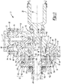
- an exemplary axle assembly constructed in accordance with the present invention is generally indicated by reference numeral 10.
- the axle assembly 10 is an independent front axle assembly having disconnecting capabilities, but it will be appreciated that the present invention has application to various other types of axle assemblies and as such, the particular example illustrated and described herein is not intended to limit the scope of the invention as claimed in any way.
- the axle assembly 10 can include a housing assembly 12, an input pinion 14, a ring gear 16, a differential assembly 18, a second output member or axle shaft 20, a first output member or axle shaft 22 and a clutch or coupling 24.
- the housing assembly 12 can be configured to house the input pinion 14, the ring gear 16, the differential assembly 18, and the coupling 24.
- the housing assembly 12 can include a first housing member 30, a second housing member 32, a seal mount 34 and an annular bearing mount 36.
- the first housing member 30 can define a first cavity 40, which can be disposed about a first axis 42, and a second cavity 44 that can be disposed about a second axis 46.
- the first cavity 40 can be configured to receive the input pinion 14 therein, while the second cavity 44 can be configured to receive the ring gear 16 therein.
- the second housing member 32 can define a third cavity 48, which can be configured to receive the differential assembly 18 and the coupling 24 therein.
- the second housing member 32 is configured to be separable from the first housing member 30 along the second axis 46.
- the input pinion 14 can be received in the first cavity 40 and can be supported for rotation about the first axis 42 by a first bearing 50 that is configured to transmit axial loads between the input pinion 14 and the housing assembly 12 in two (i.e., opposite) directions along the first axis 42. Accordingly, it will be appreciated that axial loads transmitted through the input pinion 14 are handled at least substantially (if not completely) by the first bearing 50.
- the first bearing 50 comprises an inner bearing race 52, which is integrally formed with the input pinion 14, an outer bearing race 54, which is assembled to the housing assembly 12, and a plurality of bearing balls 56 that are received between the inner and outer bearing races 52 and 54.
- the outer bearing race 54 can be abutted against a shoulder 58 formed in a bore that forms at least a portion of the first cavity 40 in the first housing member 30.
- the seal mount 34 can abut an opposite end of the outer bearing race 54 and can be fixedly and sealingly coupled to the first housing member 30.
- a pinion shaft seal 60 can be mounted to the seal mount 34 and sealingly engage a shaft portion of the input pinion 14.
- the outer bearing race 54 is shown to be comprised of two discrete race members, but it will be appreciated that the outer bearing race 54 could be formed as a single piece.
- the first bearing 50 has been illustrated and described as being a four-point angular contact bearing, it will be appreciated that other types of bearings, including a tapered roller bearing, could be employed in the alternative.
- the ring gear 16 can be meshingly engaged to a pinion gear 62 on the input pinion 14 and can be supported for rotation about a second axis 46 by a second bearing 64 that is configured to transmit axial loads between the ring gear 16 and the housing assembly 12 in two (i.e., opposite) directions along the second axis 46. Accordingly, it will be appreciated that the axial loads transmitted through the ring gear 16 are handled at least partly by the second bearing 64.
- the second bearing comprises an inner bearing race 66, which is assembled to the housing assembly 12, and an outer bearing race 68, which is integrally formed with the ring gear 16, and a plurality of bearing balls 70 that are received between the inner and outer bearing races 66 and 68.
- the inner bearing race 66 can be received on a tubular projection 74 formed on the first housing member 30 and can abut a shoulder 76 that is formed by the intersection of the tubular projection 74 with a remainder of the first housing member 30.
- the annular bearing mount 36 can be engaged against an opposite side of the inner bearing race 66 and a plurality of threaded fasteners 77 can be received through the annular bearing mount 36 and threadably engaged to threaded holes formed in the tubular projection 74. It will be appreciated that various other means may be employed to secure the inner bearing race 66 to the tubular projection 74.
- tubular projection 74 could be threaded on its exterior diameter and a relatively large nut (not shown) could be threaded to the tubular projection 74 and abutted against the inner bearing race 66 so that the annular bearing mount 36 could be omitted.
- the inner bearing race 66 is shown to be comprised of two discrete race members, but it will be appreciated that the inner bearing race 66 could be formed as a single piece.
- second bearing 64 has been illustrated and described as being a four-point angular contact bearing, it will be appreciated that other types of bearings, including a tapered roller bearing, could be employed in the alternative.
- a third bearing 80 can be employed to provide additional stability to the input pinion 14.
- the third bearing 80 is disposed on an axial end of the input pinion 14 so that the pinion gear 62 of the input pinion 14 is disposed along the first axis at a location that is between the first and third bearings 50 and 80.
- the third bearing 80 is illustrated as being a type of bearing that supports only radial loads (e.g., a roller bearing), it will be appreciated that a ball bearing, which could be configured to handle some loads directed axially along the first axis 42, could be employed in the alternative.
- a fourth bearing could be employed to provide additional stability to the ring gear 16.
- the fourth bearing can be a thrust bearing that can be disposed between the ring gear 16 and the housing assembly 12 at a location that is radially outward of the second bearing 64, such as a location that supports the teeth of the ring gear 16 to thereby resist deflection of the ring gear 16.
- the differential assembly 18 can comprise a planetary gear arrangement that can have an internal gear 90, a planet carrier 92, a set of planet gears 94, and a sun gear 96.
- the internal gear 90 can be formed as an internally toothed, hollow sleeve and can be fixedly coupled to the ring gear 16 in any desired manner, such as welding.
- the planet carrier 92 can comprise a carrier body 100 and a plurality of carrier pins 102.
- the carrier body 100 can comprise first and second carrier plates 104 and 106, respectively.
- the first carrier plate 104 can have an annular plate-like portion 110 and an annular wall member 112 that can extend from the annular plate-like portion 110 toward the ring gear 16.
- a thrust bearing 114 can be received in an annular pocket 116 formed in the ring gear 16 and can abut an axial end of the annular wall member 112 and an annular face of the pocket 116 formed on the ring gear 16.
- the second carrier plate 106 can include an annular plate-like portion 120.
- Each of the carrier pins 102 can be received through corresponding holes formed in the first and second carrier plates 104 and 106 can be coupled to the first and second carrier plates 104 and 106 in any desired manner.
- the carrier pins 102 can be press-fit to the second carrier plate 106 and an internal snap ring 122 can be received into a slot 124 formed in each carrier pin 102 to thereby limit movement of the first carrier plate 104 on the carrier pins 102 in a direction away from the second carrier plate 106.
- the set of planet gears 94 can be configured to transmit rotary loads between the internal gear 90 and the sun gear 96.
- the set of planet gears 94 comprises a plurality of planet gear pairs, with each planet gear pair having a first planet gear (not specifically shown), which is meshingly engaged to the teeth of the internal gear 90, and a second planet gear 130 that is meshingly engaged to the teeth of the first planet gear and the teeth of the sun gear 96.
- Each of the first planet gears and the second planet gears 130 is journally supported on an associated one of the carrier pins 102 for rotation thereon.
- the sun gear 96 can have a gear portion 138, which can be received in the carrier body 100, and an output portion 140 that can be received through the first carrier plate 104.
- the output portion 140 can be tubular in shape and a bearing 142, such as a roller bearing, can be employed to support the output portion 140 for rotation about the second axis 46 relative to the first housing member 30.
- the output portion 140 can comprise a plurality of internal spline teeth 144 that can be meshingly engaged to external spline teeth 146 formed on the second axle shaft 20.
- a snap ring or circlip 148 can be received in a groove 150 formed in second axle shaft 20; the circlip 148 can contact the axially inboard end of the internal spline teeth 144 in the output portion 140 to thereby limit movement of the second axle shaft 20 along the second axis 46 in a direction away from the sun gear 96.
- the first axle shaft 22 can be received through the second housing member 32 and can be supported for rotation about the second axis 46 relative to the second housing member 32 by a bearing 150.
- a suitable bearing such as a roller bearing 152, can be employed between the second carrier plate 106 and the first axle shaft 22 to support the second carrier plate 106 for rotation about the second axis 46.
- the coupling 24 can comprise a first coupling member 160, a second coupling member 162, a third coupling member 164, a biasing spring 166, and an actuator 168.
- the first coupling member 160 can be integrally formed with the second carrier plate 106 and can comprise a plurality of external teeth 170 that can be formed about the exterior periphery of the annular plate-like portion 120 of the second carrier plate 106.
- the second coupling member 162 can be an annular structure that can be fixedly coupled to the first axle shaft 22 and extend generally parallel to the second carrier plate 106.
- the second coupling member 162 can include a plurality of external teeth 172 about its exterior periphery.
- the external teeth 170 and the external teeth 172 can be formed as spline teeth having a 20 degree pressure angle and can have a common pitch diameter, which can optionally be larger than: a) twice the radius from the center of any one of the carrier pins 102 to the second axis 46; b) twice the radius from the center of any one of the bearing balls 70 to the second axis 46; c) any portion of the output of the differential assembly 18 that is coupled to the first axle shaft for common rotation (e.g., the sun gear 96 in the example provided); and/or d) a minimum diameter of the ring gear 16.
- a radius of the pitch diameter of the external teeth 170 and the external teeth 172 can be optionally sized to terminate (at the pitch diameter) at a location that: a) is closer to a line extending through the centers of each of the bearing balls 56 that support the input pinion 14 than to the second axis 46; b) is farther from the second axis 46 than any portion of the second bearing 64; c) is farther from the second axis 46 than any portion of the third bearing 80; and/or d) is in a plane that is perpendicular to and intersects the first axis 42 within a zone in which the teeth of the pinion gear 62 mesh with the teeth of the ring gear 16.
- a thrust bearing 178 can be received between the second carrier plate 106 and the second coupling member 162.
- the third coupling member 164 can be wholly or partly formed from a ferro-magnetic material and can include an annular hub 180, an annular flange 182 and a drum 184.
- the annular hub 180 can be received on the first axle shaft 22 for sliding movement thereon along the second axis 46.
- the annular flange 182 can be fixedly coupled to the annular hub 180 and can extend outwardly therefrom.
- the drum 184 can be fixedly coupled to the outer peripheral end of the annular flange 182 and can comprise a plurality of internal teeth 188 that can be meshed with the external teeth 172 of the second coupling member 162 and the external teeth 170 of the first coupling member 160.
- the biasing spring 166 can be a helical compression spring that can be disposed concentrically about the first axle shaft 22 and can be abutted against an external snap ring 190, which can be mounted on the first axle shaft 22, and the third coupling member 164 to bias the third coupling member 164 along the second axis 46 toward the first coupling member 160 such that the internal teeth 188 of the drum 184 engage the external teeth 170 on the first coupling member 160.
- the biasing spring 166 biases the third coupling member 164 along the second axis 46 into a position in which the third coupling member 164 is engaged to the first coupling member 160 (in addition to the second coupling member 162) so that rotary power can be transmitted between the planet carrier 92 and the first axle shaft 22.
- the biasing spring 166 is received into a counterbore 200 formed in the annular hub 180 of the third coupling member 164.
- the actuator 168 can be configured to selectively move the third coupling member 164 along the second axis 46 in a direction away from the second planet carrier 92 to thereby disengage the internal teeth 188 of the drum 184 from the external teeth 170 of the first coupling member 160.
- the actuator 168 comprises an electromagnet 204 that is configured to generate a magnetic field that interacts with the ferro-magnetic material of the third coupling member 164 to cause the third coupling member 164 to move along the second axis 46 against the force of the biasing spring 166 by an appropriate distance to thereby disengage the internal teeth 188 of the drum 184 from the external teeth 170 of the first coupling member 160.
- the relatively large pitch diameter of the external teeth 170 of the first coupling member 160 permits the rotary load that is transmitted between the planet carrier 92 and the first axle shaft 22 to be distributed over a relatively large number of teeth.
- the load on any one tooth is relatively low and consequently, the depth of the external teeth 170 (i.e., the dimension of the external teeth 170 taken in a direction parallel to the second axis 46) on the first coupling member 160 (and the external teeth 170 on the second coupling member 162) can be relatively small, which permits the third coupling member 164 to have a relatively small stroke along the second axis 46, such as a stroke that is less than or equal to about 6.0 mm, preferably less or equal to about 5.0 mm and more preferably less than or equal to about 4.0 mm.
- the third coupling member 164 has a stroke that is less than or equal to about 3.0 mm.
- the coupling 24 has been described and illustrated as being “normally engaged” (i.e., capable of transmitting rotary power between the planet carrier 92 and the first axle shaft 22 when the actuator 168 is not actively powered), it will be appreciated that the coupling 24 could be configured as being “normally disengaged” (i.e., configured to disengage the third coupling member 164 from the first coupling member 160 when the actuator 168 is not actively powered so that rotary power is not transmitted between the planet carrier 92 and the first axle shaft 22).
- the biasing spring 166 could be positioned between the second and third coupling members 162 and 164 to bias the third coupling member 164 along the second axis 46 in a direction away from the first coupling member 160.
- the biasing spring 166 biases the third coupling member 164 along the second axis 46 into a position in which the third coupling member 164 is disengaged from the first coupling member 160 (but not the second coupling member 162) so that rotary power cannot be transmitted between the planet carrier 92 and the first axle shaft 22.
- the electromagnet 204 can be selectively operated to generate a magnetic field, which can interact with the ferro-magnetic material of the third coupling member 164 to cause the third coupling member 164 to overcome the force of the biasing spring 166 and move along the second axis 46 to engage the internal teeth 188 of the drum 184 with the external teeth 170 of the first coupling member 160.
- the electromagnet 204 can be sized relatively small in diameter due to the relatively large pitch diameter of the external teeth 170, 172, which permits a relatively large number of turns of a small diameter wire to be employed so that a relatively strong magnetic field can be created with relatively little copper.
- the coupling 24 could be configured such that the third coupling member 164 is moveable into a third position in which it engages or locks to the internal gear 90 (to thereby inhibit speed differentiation between the first and second axle shafts 22 and 20) while the first and second coupling members 160 and 162 are coupled for rotation to one another.
- external teeth could be formed on the drum 184 and could engage the internal teeth 188 of the internal gear 90 when the third coupling member 164 is positioned in the third position.
- the drum 184 could include a plurality of face teeth, which can extend from the drum 184 on a side opposite the annular flange 182; the face teeth can be selectively engaged to mating face teeth that can be formed on an axial end of the internal gear 90.
Claims (10)
- Achsanordnung (10), umfassend:eine Gehäuseanordnung (12);ein Eingangsritzel(14), das an der Gehäuseanordnung (12) zur Drehung um eine erste Achse (42) angebracht ist;ein Tellerrad (16), das an der Gehäuseanordnung (12) zur Drehung um eine zweite Achse (46), die nicht parallel zu der ersten Achse (42) ist, angebracht ist;eine Differentialanordnung (18) mit einem Hohlrad (90), einem Planetenträger (92), mehreren Planetenrädern (94) und einem Sonnenrad (96), wobei das Hohlrad (90) mit dem Tellerrad (16) zur Drehung damit gekoppelt ist, wobei der Planetenträger (92) einen Trägerkörper (100) und mehrere Trägerstifte (102) aufweist, die fest mit dem Trägerkörper (100) gekoppelt sind, wobei jedes der Planetenräder (94) auf einem entsprechenden der Trägerstifte (102) drehbar gelagert ist, wobei mindestens ein erster Abschnitt der Planetenräder (94) mit dem Hohlrad (90) in Eingriff steht, wobei mindestens ein zweiter Abschnitt der Planetenräder (94) mit dem Sonnenrad (96) in Eingriff steht;ein erstes Ausgangselement (22);ein zweites Ausgangselement (20); dadurch gekennzeichnet, dass das zweite Ausgangselement (20) mit dem Sonnenrad (96) zur Drehung damit gekoppelt ist; und dass die Achsanordnung (10) ferner Folgendes umfasst:eine Kupplung (24), die betätigbar ist, um das erste Ausgangselement (22) selektiv mit dem Trägerkörper (100) zu koppeln,wobei die Kupplung (24) ein Kopplungsglied (164) umfasst, das axial verschiebbar an dem ersten Ausgangselement (22) angebracht ist, undwobei der Trägerkörper (100) einen ersten Satz Außenzähne (170) aufweist, wobei das erste Ausgangselement (22) einen zweiten Satz Außenzähne (172) aufweist und wobei das Kopplungsglied (164) mindestens einen Satz Innenzähne (188) aufweist, die mit dem ersten und dem zweiten Satz Außenzähne (170, 172) in Eingriff bringbar sind.
- Achsanordnung (10) nach Anspruch 1, wobei das Kopplungsglied (164) entlang der zweiten Achse (46) zwischen einer ersten Position, in der der mindestens eine Satz Innenzähne (188) mit sowohl dem ersten als auch dem zweiten Satz Außenzähne (170, 172) in Eingriff steht, und einer zweiten Position, in der der mindestens eine Satz Innenzähne (188) mit dem ersten Satz Außenzähne (170) nicht in Eingriff steht, beweglich ist.
- Achsanordnung (10) nach Anspruch 2, wobei der erste und der zweite Satz Außenzähne (170, 172) jeweilige Teilkreisdurchmesser aufweisen, die größer sind als:a) das Doppelte des Abstands von der Mitte eines der Trägerstifte (102) zu der zweiten Achse (46);b) das Doppelte des Abstands von der zweiten Achse (46) zu einer Mitte eines Wälzlagerelements (70) eines Lagers (64), das das Tellerrad (16) zur Drehung auf der Gehäuseanordnung (12) trägt;c) das Sonnenrad (96); und/oderd) ein Mindestdurchmesser des Hohlrads (16).
- Achsanordnung (10) nach Anspruch 1, wobei der erste und der zweite Satz Außenzähne (170, 172) jeweilige Teilkreisdurchmesser aufweisen, die so bemessen sind, dass Kreise, die durch die Teilkreisdurchmesser definiert werden:a) näher an einer Linie durch die Mitten von jeder von mehreren Lagerkugeln (56) eines ersten Lagers (50), die das Eingangsritzel (14) tragen, als an der zweiten Achse (46) liegen; und/oderb) weiter von der zweiten Achse (46) entfernt sind als ein beliebiger Abschnitt eines zweiten Lagers (64), das das Tellerrad (16) zur Drehung relativ zur Gehäuseanordnung (12) trägt; und/oderc) weiter von der zweiten Achse (46) entfernt sind als ein beliebiger Abschnitt eines dritten Lagers (80), das das Eingangsritzel (14) trägt, auf einer Seite eines Zahnritzels (62), die dem ersten Lager (50) gegenüberliegt; und/oderd) in einer Ebene, die senkrecht zu der ersten Achse (42) verläuft und diese innerhalb einer Zone schneidet, in der die Zähne des Zahnritzels (62) mit den Zähnen des Tellerrads (16) kämmen, liegen.
- Achsanordnung (10) nach Anspruch 2, wobei der mindestens eine Satz Innenzähne (188) mit dem zweiten Satz Außenzähne (172) in Eingriff steht, wenn sich das Kopplungsglied (164) in der zweiten Position befindet.
- Achsanordnung (10) nach Anspruch 5, ferner eine Feder umfassend, die das Kopplungsglied (164) in Richtung der ersten Position vorspannt.
- Achsanordnung (10) nach Anspruch 1, ferner einen Linearmotor umfassend, der selektiv betreibbar ist, um das Kopplungsglied (164) in mindestens eine Richtung entlang der zweiten Achse (46) zu verschieben.
- Achsanordnung (10) nach Anspruch 7, wobei der Linearmotor einen Elektromagneten umfasst.
- Achsanordnung (10) nach Anspruch 1, ferner umfassend ein Axiallager, das zwischen dem ersten Ausgangsglied (22) und dem Trägerkörper (100) angeordnet ist und dieses berührt.
- Achsanordnung (10) nach Anspruch 1, wobei das Eingangsritzel (14) und/oder das Tellerrad (16) zur Drehung relativ zur Gehäuseanordnung über ein Vierpunkt-Schräglager getragen wird.
Applications Claiming Priority (2)
| Application Number | Priority Date | Filing Date | Title |
|---|---|---|---|
| US201662287076P | 2016-01-26 | 2016-01-26 | |
| PCT/US2017/013772 WO2017132006A1 (en) | 2016-01-26 | 2017-01-17 | Disconnectable axle assembly having a planetary differential |
Publications (3)
| Publication Number | Publication Date |
|---|---|
| EP3408111A1 EP3408111A1 (de) | 2018-12-05 |
| EP3408111A4 EP3408111A4 (de) | 2019-08-28 |
| EP3408111B1 true EP3408111B1 (de) | 2021-09-22 |
Family
ID=59398650
Family Applications (1)
| Application Number | Title | Priority Date | Filing Date |
|---|---|---|---|
| EP17744690.3A Active EP3408111B1 (de) | 2016-01-26 | 2017-01-17 | Trennbare achsanordnung mit einem planetendifferential |
Country Status (4)
| Country | Link |
|---|---|
| US (1) | US10710454B2 (de) |
| EP (1) | EP3408111B1 (de) |
| CN (1) | CN108463354B (de) |
| WO (1) | WO2017132006A1 (de) |
Families Citing this family (2)
| Publication number | Priority date | Publication date | Assignee | Title |
|---|---|---|---|---|
| US20190063576A1 (en) * | 2017-08-25 | 2019-02-28 | American Axle & Manufacturing, Inc. | Disconnecting axle assembly including an asymmetrically geared differential |
| CN210920014U (zh) * | 2019-09-05 | 2020-07-03 | 北京致行慕远科技有限公司 | 车辆及其车桥 |
Family Cites Families (34)
| Publication number | Priority date | Publication date | Assignee | Title |
|---|---|---|---|---|
| US3195371A (en) * | 1961-09-21 | 1965-07-20 | Eaton Mfg Co | Vehicle axle mechanism |
| US3413873A (en) * | 1967-05-08 | 1968-12-03 | Rockwell Standard Company | Multi-speed planetary drive axle assembly |
| US4207780A (en) * | 1976-07-28 | 1980-06-17 | Rockwell International Corporation | Multi-speed planetary drive axle assembly |
| US4227427A (en) * | 1977-09-08 | 1980-10-14 | Dana Corporation | Drive unit assembly |
| US4757727A (en) * | 1985-02-25 | 1988-07-19 | Tochigifujisangyo Kabushikigaisha | Differential device for a power transmission apparatus |
| GB8509056D0 (en) * | 1985-04-09 | 1985-05-15 | Smallfry Ltd | Differential gear drive |
| US4677875A (en) * | 1985-12-09 | 1987-07-07 | American Motors Corporation | Transfer case for multiple drive axle vehicle |
| US4677873A (en) * | 1985-12-23 | 1987-07-07 | Chrysler Motors Corporation | Transfer case with inter-axle dual-planetary differential |
| JP2615086B2 (ja) * | 1987-11-04 | 1997-05-28 | 富士重工業株式会社 | センターデフ付4輪駆動車 |
| JP2525611Y2 (ja) * | 1990-06-05 | 1997-02-12 | 栃木富士産業株式会社 | 電磁多板クラッチ |
| US5322484A (en) * | 1992-12-22 | 1994-06-21 | Dana Corporation | Locking differential with clutch activated by electrorheological fluid coupling |
| US6193629B1 (en) * | 1999-05-07 | 2001-02-27 | Ford Global Technologies, Inc. | Shifting mechanism |
| US6283379B1 (en) | 2000-02-14 | 2001-09-04 | Kic Thermal Profiling | Method for correlating processor and part temperatures using an air temperature sensor for a conveyorized thermal processor |
| US7008345B2 (en) * | 2003-10-27 | 2006-03-07 | Automotive Components Holdings Inc. | Planetary differential |
| WO2009038909A1 (en) | 2007-09-13 | 2009-03-26 | Borgwarner Inc. | Controlled differntial actuator |
| CA2677392C (en) | 2008-09-09 | 2016-11-29 | Magna Powertrain Usa, Inc. | Power take-off unit with active coupling and hypoid disconnect system |
| CN201538200U (zh) * | 2009-11-25 | 2010-08-04 | 中国三江航天工业集团公司特种车辆技术中心 | 超重型矿用车驱动桥 |
| US8986151B2 (en) | 2009-12-08 | 2015-03-24 | American Axle & Manufacturing, Inc. | Disconnecting rear drive axle for longitudinally arranged powertrains |
| US8449430B2 (en) * | 2010-02-05 | 2013-05-28 | Honda Motor Co., Ltd. | Transversely mounted transaxle having a low range gear assembly and powertrain for a vehicle including same |
| JP2011173440A (ja) * | 2010-02-23 | 2011-09-08 | Aisin Ai Co Ltd | 四輪駆動ハイブリッド車用動力伝達装置 |
| US9731598B2 (en) * | 2010-07-23 | 2017-08-15 | Fca Us Llc | Multi-mode drive system for transaxle applications |
| US8795126B2 (en) | 2012-05-14 | 2014-08-05 | American Axle & Manufacturing, Inc. | Disconnectable driveline for all-wheel drive vehicle |
| US8961353B2 (en) | 2012-05-14 | 2015-02-24 | American Axle & Manufacturing, Inc. | Two-speed disconnecting driveline with one reduction gearset |
| US8469854B1 (en) | 2012-05-15 | 2013-06-25 | American Axle & Manufacturing, Inc. | Disconnectable driveline for all-wheel drive vehicle |
| WO2014011230A1 (en) * | 2012-07-09 | 2014-01-16 | Eaton Corporation | Clutch system |
| US8986148B2 (en) | 2012-10-05 | 2015-03-24 | American Axle & Manufacturing, Inc. | Single speed and two-speed disconnecting axle arrangements |
| US9028358B2 (en) * | 2013-03-15 | 2015-05-12 | American Axle & Manufacturing, Inc. | Disconnecting axle assembly |
| US9103427B2 (en) * | 2013-03-15 | 2015-08-11 | American Axle & Manufacturing, Inc. | Axle assembly |
| US9346354B2 (en) | 2014-03-03 | 2016-05-24 | American Axle & Manufacturing, Inc. | Disconnecting driveline component |
| US9302581B1 (en) | 2014-10-10 | 2016-04-05 | American Axle & Manufacturing, Inc. | All-wheel drive driveline with disconnecting axle |
| US10323699B2 (en) * | 2015-07-02 | 2019-06-18 | Dana Automotive Systems Group, Llc | Electromagnetic connect/disconnect system for a vehicle |
| US10118485B2 (en) | 2015-11-20 | 2018-11-06 | American Axle & Manufacturing, Inc. | Disconnecting all-wheel drive driveline having rear drive module with disconnection and differential locking clutches |
| US9895971B2 (en) | 2015-11-20 | 2018-02-20 | American Axle & Manufacturing, Inc. | Disconnecting all-wheel drive driveline having flat tow capabilities |
| US10391861B2 (en) | 2016-07-27 | 2019-08-27 | American Axle & Manufacturing, Inc. | Axle assembly with disconnecting differential output |
-
2017
- 2017-01-17 WO PCT/US2017/013772 patent/WO2017132006A1/en active Application Filing
- 2017-01-17 EP EP17744690.3A patent/EP3408111B1/de active Active
- 2017-01-17 CN CN201780006667.4A patent/CN108463354B/zh active Active
-
2018
- 2018-07-02 US US16/024,937 patent/US10710454B2/en active Active
Also Published As
| Publication number | Publication date |
|---|---|
| US10710454B2 (en) | 2020-07-14 |
| CN108463354B (zh) | 2021-04-30 |
| WO2017132006A1 (en) | 2017-08-03 |
| CN108463354A (zh) | 2018-08-28 |
| EP3408111A1 (de) | 2018-12-05 |
| EP3408111A4 (de) | 2019-08-28 |
| US20180319277A1 (en) | 2018-11-08 |
Similar Documents
| Publication | Publication Date | Title |
|---|---|---|
| US10234009B2 (en) | Differential limiting device for vehicle | |
| US8167764B2 (en) | Locking power transmitting device | |
| EP3095634A2 (de) | Achsanordnung mit einer konischen keilwellenanordnung | |
| US20140128192A1 (en) | Motor driving force transmission system | |
| EP2110582B1 (de) | Differentialvorrichtung für fahrzeug | |
| US20080182702A1 (en) | Electronic locking differential with direct locking state detection system | |
| EP3372434A1 (de) | Achsaggregat mit einem antriebsritzelstützlager und montageverfahren | |
| US10323693B2 (en) | Disconnect system for an axle | |
| US6695739B2 (en) | Ultra narrow adjustable differential assembly | |
| US8051744B2 (en) | Locking differential | |
| EP3193044B1 (de) | Differentialanordnung mit stegwellenarretierung | |
| AU2016216642A1 (en) | Axle assembly having a bearing preload bolt | |
| US10197144B2 (en) | Drive unit with torque vectoring and an axle disconnect and reconnect mechanism | |
| US10710454B2 (en) | Disconnectable axle assembly having a planetary differential | |
| KR20220050152A (ko) | 최종 구동 기어에 대한 부하를 공유하는 병렬 트윈 기어 쌍을 갖는 변속기를 구비한 전기 구동 모듈 | |
| US8961349B2 (en) | Differential with tailored torque bias ratios | |
| US10487933B2 (en) | Axle assembly having ring gear with unitarily and integrally formed portion of a bearing race | |
| EP3473890B1 (de) | Antriebsmodul | |
| US20090305834A1 (en) | Differential apparatus for vehicle | |
| JP2017096338A (ja) | 動力伝達装置およびその軸受の予圧調整方法 |
Legal Events
| Date | Code | Title | Description |
|---|---|---|---|
| STAA | Information on the status of an ep patent application or granted ep patent |
Free format text: STATUS: THE INTERNATIONAL PUBLICATION HAS BEEN MADE |
|
| PUAI | Public reference made under article 153(3) epc to a published international application that has entered the european phase |
Free format text: ORIGINAL CODE: 0009012 |
|
| STAA | Information on the status of an ep patent application or granted ep patent |
Free format text: STATUS: REQUEST FOR EXAMINATION WAS MADE |
|
| 17P | Request for examination filed |
Effective date: 20180824 |
|
| AK | Designated contracting states |
Kind code of ref document: A1 Designated state(s): AL AT BE BG CH CY CZ DE DK EE ES FI FR GB GR HR HU IE IS IT LI LT LU LV MC MK MT NL NO PL PT RO RS SE SI SK SM TR |
|
| AX | Request for extension of the european patent |
Extension state: BA ME |
|
| DAV | Request for validation of the european patent (deleted) | ||
| DAX | Request for extension of the european patent (deleted) | ||
| A4 | Supplementary search report drawn up and despatched |
Effective date: 20190731 |
|
| RIC1 | Information provided on ipc code assigned before grant |
Ipc: B60K 17/16 20060101ALI20190725BHEP Ipc: B60B 35/18 20060101ALI20190725BHEP Ipc: B60K 17/35 20060101ALI20190725BHEP Ipc: B60B 35/14 20060101ALI20190725BHEP Ipc: B60B 35/12 20060101AFI20190725BHEP Ipc: B60B 35/16 20060101ALI20190725BHEP |
|
| STAA | Information on the status of an ep patent application or granted ep patent |
Free format text: STATUS: EXAMINATION IS IN PROGRESS |
|
| 17Q | First examination report despatched |
Effective date: 20200818 |
|
| STAA | Information on the status of an ep patent application or granted ep patent |
Free format text: STATUS: EXAMINATION IS IN PROGRESS |
|
| REG | Reference to a national code |
Ref country code: DE Ref legal event code: R079 Ref document number: 602017046394 Country of ref document: DE Free format text: PREVIOUS MAIN CLASS: B60B0035120000 Ipc: B60K0017020000 |
|
| GRAP | Despatch of communication of intention to grant a patent |
Free format text: ORIGINAL CODE: EPIDOSNIGR1 |
|
| STAA | Information on the status of an ep patent application or granted ep patent |
Free format text: STATUS: GRANT OF PATENT IS INTENDED |
|
| RIC1 | Information provided on ipc code assigned before grant |
Ipc: B60B 35/12 20060101ALI20210331BHEP Ipc: B60B 35/16 20060101ALI20210331BHEP Ipc: B60K 17/35 20060101ALI20210331BHEP Ipc: B60K 17/16 20060101ALI20210331BHEP Ipc: B60K 23/08 20060101ALI20210331BHEP Ipc: B60K 17/02 20060101AFI20210331BHEP |
|
| INTG | Intention to grant announced |
Effective date: 20210414 |
|
| GRAS | Grant fee paid |
Free format text: ORIGINAL CODE: EPIDOSNIGR3 |
|
| GRAA | (expected) grant |
Free format text: ORIGINAL CODE: 0009210 |
|
| STAA | Information on the status of an ep patent application or granted ep patent |
Free format text: STATUS: THE PATENT HAS BEEN GRANTED |
|
| AK | Designated contracting states |
Kind code of ref document: B1 Designated state(s): AL AT BE BG CH CY CZ DE DK EE ES FI FR GB GR HR HU IE IS IT LI LT LU LV MC MK MT NL NO PL PT RO RS SE SI SK SM TR |
|
| REG | Reference to a national code |
Ref country code: GB Ref legal event code: FG4D |
|
| REG | Reference to a national code |
Ref country code: IE Ref legal event code: FG4D |
|
| REG | Reference to a national code |
Ref country code: DE Ref legal event code: R096 Ref document number: 602017046394 Country of ref document: DE |
|
| REG | Reference to a national code |
Ref country code: CH Ref legal event code: EP Ref country code: AT Ref legal event code: REF Ref document number: 1432059 Country of ref document: AT Kind code of ref document: T Effective date: 20211015 |
|
| REG | Reference to a national code |
Ref country code: LT Ref legal event code: MG9D |
|
| REG | Reference to a national code |
Ref country code: NL Ref legal event code: MP Effective date: 20210922 |
|
| PG25 | Lapsed in a contracting state [announced via postgrant information from national office to epo] |
Ref country code: BG Free format text: LAPSE BECAUSE OF FAILURE TO SUBMIT A TRANSLATION OF THE DESCRIPTION OR TO PAY THE FEE WITHIN THE PRESCRIBED TIME-LIMIT Effective date: 20211222 Ref country code: LT Free format text: LAPSE BECAUSE OF FAILURE TO SUBMIT A TRANSLATION OF THE DESCRIPTION OR TO PAY THE FEE WITHIN THE PRESCRIBED TIME-LIMIT Effective date: 20210922 Ref country code: NO Free format text: LAPSE BECAUSE OF FAILURE TO SUBMIT A TRANSLATION OF THE DESCRIPTION OR TO PAY THE FEE WITHIN THE PRESCRIBED TIME-LIMIT Effective date: 20211222 Ref country code: FI Free format text: LAPSE BECAUSE OF FAILURE TO SUBMIT A TRANSLATION OF THE DESCRIPTION OR TO PAY THE FEE WITHIN THE PRESCRIBED TIME-LIMIT Effective date: 20210922 Ref country code: SE Free format text: LAPSE BECAUSE OF FAILURE TO SUBMIT A TRANSLATION OF THE DESCRIPTION OR TO PAY THE FEE WITHIN THE PRESCRIBED TIME-LIMIT Effective date: 20210922 Ref country code: RS Free format text: LAPSE BECAUSE OF FAILURE TO SUBMIT A TRANSLATION OF THE DESCRIPTION OR TO PAY THE FEE WITHIN THE PRESCRIBED TIME-LIMIT Effective date: 20210922 Ref country code: HR Free format text: LAPSE BECAUSE OF FAILURE TO SUBMIT A TRANSLATION OF THE DESCRIPTION OR TO PAY THE FEE WITHIN THE PRESCRIBED TIME-LIMIT Effective date: 20210922 |
|
| REG | Reference to a national code |
Ref country code: AT Ref legal event code: MK05 Ref document number: 1432059 Country of ref document: AT Kind code of ref document: T Effective date: 20210922 |
|
| PG25 | Lapsed in a contracting state [announced via postgrant information from national office to epo] |
Ref country code: LV Free format text: LAPSE BECAUSE OF FAILURE TO SUBMIT A TRANSLATION OF THE DESCRIPTION OR TO PAY THE FEE WITHIN THE PRESCRIBED TIME-LIMIT Effective date: 20210922 Ref country code: GR Free format text: LAPSE BECAUSE OF FAILURE TO SUBMIT A TRANSLATION OF THE DESCRIPTION OR TO PAY THE FEE WITHIN THE PRESCRIBED TIME-LIMIT Effective date: 20211223 |
|
| PG25 | Lapsed in a contracting state [announced via postgrant information from national office to epo] |
Ref country code: AT Free format text: LAPSE BECAUSE OF FAILURE TO SUBMIT A TRANSLATION OF THE DESCRIPTION OR TO PAY THE FEE WITHIN THE PRESCRIBED TIME-LIMIT Effective date: 20210922 |
|
| PG25 | Lapsed in a contracting state [announced via postgrant information from national office to epo] |
Ref country code: IS Free format text: LAPSE BECAUSE OF FAILURE TO SUBMIT A TRANSLATION OF THE DESCRIPTION OR TO PAY THE FEE WITHIN THE PRESCRIBED TIME-LIMIT Effective date: 20220122 Ref country code: SK Free format text: LAPSE BECAUSE OF FAILURE TO SUBMIT A TRANSLATION OF THE DESCRIPTION OR TO PAY THE FEE WITHIN THE PRESCRIBED TIME-LIMIT Effective date: 20210922 Ref country code: RO Free format text: LAPSE BECAUSE OF FAILURE TO SUBMIT A TRANSLATION OF THE DESCRIPTION OR TO PAY THE FEE WITHIN THE PRESCRIBED TIME-LIMIT Effective date: 20210922 Ref country code: PT Free format text: LAPSE BECAUSE OF FAILURE TO SUBMIT A TRANSLATION OF THE DESCRIPTION OR TO PAY THE FEE WITHIN THE PRESCRIBED TIME-LIMIT Effective date: 20220124 Ref country code: PL Free format text: LAPSE BECAUSE OF FAILURE TO SUBMIT A TRANSLATION OF THE DESCRIPTION OR TO PAY THE FEE WITHIN THE PRESCRIBED TIME-LIMIT Effective date: 20210922 Ref country code: NL Free format text: LAPSE BECAUSE OF FAILURE TO SUBMIT A TRANSLATION OF THE DESCRIPTION OR TO PAY THE FEE WITHIN THE PRESCRIBED TIME-LIMIT Effective date: 20210922 Ref country code: ES Free format text: LAPSE BECAUSE OF FAILURE TO SUBMIT A TRANSLATION OF THE DESCRIPTION OR TO PAY THE FEE WITHIN THE PRESCRIBED TIME-LIMIT Effective date: 20210922 Ref country code: EE Free format text: LAPSE BECAUSE OF FAILURE TO SUBMIT A TRANSLATION OF THE DESCRIPTION OR TO PAY THE FEE WITHIN THE PRESCRIBED TIME-LIMIT Effective date: 20210922 Ref country code: CZ Free format text: LAPSE BECAUSE OF FAILURE TO SUBMIT A TRANSLATION OF THE DESCRIPTION OR TO PAY THE FEE WITHIN THE PRESCRIBED TIME-LIMIT Effective date: 20210922 Ref country code: AL Free format text: LAPSE BECAUSE OF FAILURE TO SUBMIT A TRANSLATION OF THE DESCRIPTION OR TO PAY THE FEE WITHIN THE PRESCRIBED TIME-LIMIT Effective date: 20210922 |
|
| REG | Reference to a national code |
Ref country code: DE Ref legal event code: R097 Ref document number: 602017046394 Country of ref document: DE |
|
| PG25 | Lapsed in a contracting state [announced via postgrant information from national office to epo] |
Ref country code: DK Free format text: LAPSE BECAUSE OF FAILURE TO SUBMIT A TRANSLATION OF THE DESCRIPTION OR TO PAY THE FEE WITHIN THE PRESCRIBED TIME-LIMIT Effective date: 20210922 |
|
| PLBE | No opposition filed within time limit |
Free format text: ORIGINAL CODE: 0009261 |
|
| STAA | Information on the status of an ep patent application or granted ep patent |
Free format text: STATUS: NO OPPOSITION FILED WITHIN TIME LIMIT |
|
| 26N | No opposition filed |
Effective date: 20220623 |
|
| PG25 | Lapsed in a contracting state [announced via postgrant information from national office to epo] |
Ref country code: MC Free format text: LAPSE BECAUSE OF FAILURE TO SUBMIT A TRANSLATION OF THE DESCRIPTION OR TO PAY THE FEE WITHIN THE PRESCRIBED TIME-LIMIT Effective date: 20210922 |
|
| REG | Reference to a national code |
Ref country code: CH Ref legal event code: PL |
|
| REG | Reference to a national code |
Ref country code: BE Ref legal event code: MM Effective date: 20220131 |
|
| PG25 | Lapsed in a contracting state [announced via postgrant information from national office to epo] |
Ref country code: LU Free format text: LAPSE BECAUSE OF NON-PAYMENT OF DUE FEES Effective date: 20220117 |
|
| PG25 | Lapsed in a contracting state [announced via postgrant information from national office to epo] |
Ref country code: SI Free format text: LAPSE BECAUSE OF FAILURE TO SUBMIT A TRANSLATION OF THE DESCRIPTION OR TO PAY THE FEE WITHIN THE PRESCRIBED TIME-LIMIT Effective date: 20210922 Ref country code: BE Free format text: LAPSE BECAUSE OF NON-PAYMENT OF DUE FEES Effective date: 20220131 |
|
| PG25 | Lapsed in a contracting state [announced via postgrant information from national office to epo] |
Ref country code: LI Free format text: LAPSE BECAUSE OF NON-PAYMENT OF DUE FEES Effective date: 20220131 Ref country code: CH Free format text: LAPSE BECAUSE OF NON-PAYMENT OF DUE FEES Effective date: 20220131 |
|
| PG25 | Lapsed in a contracting state [announced via postgrant information from national office to epo] |
Ref country code: IT Free format text: LAPSE BECAUSE OF FAILURE TO SUBMIT A TRANSLATION OF THE DESCRIPTION OR TO PAY THE FEE WITHIN THE PRESCRIBED TIME-LIMIT Effective date: 20210922 Ref country code: IE Free format text: LAPSE BECAUSE OF NON-PAYMENT OF DUE FEES Effective date: 20220117 |
|
| PGFP | Annual fee paid to national office [announced via postgrant information from national office to epo] |
Ref country code: FR Payment date: 20230124 Year of fee payment: 7 |
|
| PGFP | Annual fee paid to national office [announced via postgrant information from national office to epo] |
Ref country code: GB Payment date: 20230119 Year of fee payment: 7 Ref country code: DE Payment date: 20230123 Year of fee payment: 7 |
|
| PG25 | Lapsed in a contracting state [announced via postgrant information from national office to epo] |
Ref country code: HU Free format text: LAPSE BECAUSE OF FAILURE TO SUBMIT A TRANSLATION OF THE DESCRIPTION OR TO PAY THE FEE WITHIN THE PRESCRIBED TIME-LIMIT; INVALID AB INITIO Effective date: 20170117 |