EP3580419B1 - Türschliesser - Google Patents
Türschliesser Download PDFInfo
- Publication number
- EP3580419B1 EP3580419B1 EP18714009.0A EP18714009A EP3580419B1 EP 3580419 B1 EP3580419 B1 EP 3580419B1 EP 18714009 A EP18714009 A EP 18714009A EP 3580419 B1 EP3580419 B1 EP 3580419B1
- Authority
- EP
- European Patent Office
- Prior art keywords
- door
- axis
- mounting plate
- plate
- door closer
- Prior art date
- Legal status (The legal status is an assumption and is not a legal conclusion. Google has not performed a legal analysis and makes no representation as to the accuracy of the status listed.)
- Active
Links
Images


Classifications
-
- E—FIXED CONSTRUCTIONS
- E05—LOCKS; KEYS; WINDOW OR DOOR FITTINGS; SAFES
- E05F—DEVICES FOR MOVING WINGS INTO OPEN OR CLOSED POSITION; CHECKS FOR WINGS; WING FITTINGS NOT OTHERWISE PROVIDED FOR, CONCERNED WITH THE FUNCTIONING OF THE WING
- E05F3/00—Closers or openers with braking devices, e.g. checks; Construction of pneumatic or liquid braking devices
- E05F3/20—Closers or openers with braking devices, e.g. checks; Construction of pneumatic or liquid braking devices in hinges
-
- E—FIXED CONSTRUCTIONS
- E05—LOCKS; KEYS; WINDOW OR DOOR FITTINGS; SAFES
- E05D—HINGES OR SUSPENSION DEVICES FOR DOORS, WINDOWS OR WINGS
- E05D7/00—Hinges or pivots of special construction
- E05D7/0009—Adjustable hinges
-
- E—FIXED CONSTRUCTIONS
- E05—LOCKS; KEYS; WINDOW OR DOOR FITTINGS; SAFES
- E05D—HINGES OR SUSPENSION DEVICES FOR DOORS, WINDOWS OR WINGS
- E05D7/00—Hinges or pivots of special construction
- E05D7/0009—Adjustable hinges
- E05D7/0018—Adjustable hinges at the hinge axis
- E05D7/0027—Adjustable hinges at the hinge axis in an axial direction
-
- E—FIXED CONSTRUCTIONS
- E05—LOCKS; KEYS; WINDOW OR DOOR FITTINGS; SAFES
- E05F—DEVICES FOR MOVING WINGS INTO OPEN OR CLOSED POSITION; CHECKS FOR WINGS; WING FITTINGS NOT OTHERWISE PROVIDED FOR, CONCERNED WITH THE FUNCTIONING OF THE WING
- E05F1/00—Closers or openers for wings, not otherwise provided for in this subclass
- E05F1/08—Closers or openers for wings, not otherwise provided for in this subclass spring-actuated, e.g. for horizontally sliding wings
- E05F1/10—Closers or openers for wings, not otherwise provided for in this subclass spring-actuated, e.g. for horizontally sliding wings for swinging wings, e.g. counterbalance
- E05F1/12—Mechanisms in the shape of hinges or pivots, operated by springs
-
- E—FIXED CONSTRUCTIONS
- E05—LOCKS; KEYS; WINDOW OR DOOR FITTINGS; SAFES
- E05F—DEVICES FOR MOVING WINGS INTO OPEN OR CLOSED POSITION; CHECKS FOR WINGS; WING FITTINGS NOT OTHERWISE PROVIDED FOR, CONCERNED WITH THE FUNCTIONING OF THE WING
- E05F3/00—Closers or openers with braking devices, e.g. checks; Construction of pneumatic or liquid braking devices
- E05F3/04—Closers or openers with braking devices, e.g. checks; Construction of pneumatic or liquid braking devices with liquid piston brakes
- E05F3/10—Closers or openers with braking devices, e.g. checks; Construction of pneumatic or liquid braking devices with liquid piston brakes with a spring, other than a torsion spring, and a piston, the axes of which are the same or lie in the same direction
- E05F3/108—Closers or openers with braking devices, e.g. checks; Construction of pneumatic or liquid braking devices with liquid piston brakes with a spring, other than a torsion spring, and a piston, the axes of which are the same or lie in the same direction with piston rod protruding from the closer housing; Telescoping closers
-
- E—FIXED CONSTRUCTIONS
- E05—LOCKS; KEYS; WINDOW OR DOOR FITTINGS; SAFES
- E05D—HINGES OR SUSPENSION DEVICES FOR DOORS, WINDOWS OR WINGS
- E05D7/00—Hinges or pivots of special construction
- E05D7/0009—Adjustable hinges
- E05D7/0018—Adjustable hinges at the hinge axis
- E05D7/0027—Adjustable hinges at the hinge axis in an axial direction
- E05D2007/0036—Adjustable hinges at the hinge axis in an axial direction with axially fixed hinge pins
-
- E—FIXED CONSTRUCTIONS
- E05—LOCKS; KEYS; WINDOW OR DOOR FITTINGS; SAFES
- E05Y—INDEXING SCHEME ASSOCIATED WITH SUBCLASSES E05D AND E05F, RELATING TO CONSTRUCTION ELEMENTS, ELECTRIC CONTROL, POWER SUPPLY, POWER SIGNAL OR TRANSMISSION, USER INTERFACES, MOUNTING OR COUPLING, DETAILS, ACCESSORIES, AUXILIARY OPERATIONS NOT OTHERWISE PROVIDED FOR, APPLICATION THEREOF
- E05Y2600/00—Mounting or coupling arrangements for elements provided for in this subclass
- E05Y2600/10—Adjustable
- E05Y2600/30—Adjustment motion
- E05Y2600/31—Linear motion
- E05Y2600/312—Horizontal motion
-
- E—FIXED CONSTRUCTIONS
- E05—LOCKS; KEYS; WINDOW OR DOOR FITTINGS; SAFES
- E05Y—INDEXING SCHEME ASSOCIATED WITH SUBCLASSES E05D AND E05F, RELATING TO CONSTRUCTION ELEMENTS, ELECTRIC CONTROL, POWER SUPPLY, POWER SIGNAL OR TRANSMISSION, USER INTERFACES, MOUNTING OR COUPLING, DETAILS, ACCESSORIES, AUXILIARY OPERATIONS NOT OTHERWISE PROVIDED FOR, APPLICATION THEREOF
- E05Y2600/00—Mounting or coupling arrangements for elements provided for in this subclass
- E05Y2600/10—Adjustable
- E05Y2600/30—Adjustment motion
- E05Y2600/31—Linear motion
- E05Y2600/314—Vertical motion
-
- E—FIXED CONSTRUCTIONS
- E05—LOCKS; KEYS; WINDOW OR DOOR FITTINGS; SAFES
- E05Y—INDEXING SCHEME ASSOCIATED WITH SUBCLASSES E05D AND E05F, RELATING TO CONSTRUCTION ELEMENTS, ELECTRIC CONTROL, POWER SUPPLY, POWER SIGNAL OR TRANSMISSION, USER INTERFACES, MOUNTING OR COUPLING, DETAILS, ACCESSORIES, AUXILIARY OPERATIONS NOT OTHERWISE PROVIDED FOR, APPLICATION THEREOF
- E05Y2600/00—Mounting or coupling arrangements for elements provided for in this subclass
- E05Y2600/40—Mounting location; Visibility of the elements
- E05Y2600/41—Concealed
- E05Y2600/412—Concealed in the rabbet
-
- E—FIXED CONSTRUCTIONS
- E05—LOCKS; KEYS; WINDOW OR DOOR FITTINGS; SAFES
- E05Y—INDEXING SCHEME ASSOCIATED WITH SUBCLASSES E05D AND E05F, RELATING TO CONSTRUCTION ELEMENTS, ELECTRIC CONTROL, POWER SUPPLY, POWER SIGNAL OR TRANSMISSION, USER INTERFACES, MOUNTING OR COUPLING, DETAILS, ACCESSORIES, AUXILIARY OPERATIONS NOT OTHERWISE PROVIDED FOR, APPLICATION THEREOF
- E05Y2900/00—Application of doors, windows, wings or fittings thereof
- E05Y2900/10—Application of doors, windows, wings or fittings thereof for buildings or parts thereof
- E05Y2900/13—Type of wing
- E05Y2900/132—Doors
Definitions
- Embodiments of this invention relate to door closers of the type including an anchor assembly for fixing to a door frame and an actuator assembly intended for concealed fitting within the thickness of a door leaf and, more particularly, to door closers whereby the anchor assembly has an adjustor plate that is moveable relative to a frame mounting plate such that a door leaf to which the actuator assembly is mounted can be raised and lowered relative to a door frame to which the frame mounting plate is fixed.
- Embodiments of the invention also relate door closers which have a link whose length is less than approximately 40 mm.
- Door closers of the type having an anchor assembly for fixing to a door frame and an actuator assembly intended for concealed fitting within the thickness of a door leaf are disclosed in our earlier patent, GB2456508 , the content of which is hereby incorporated by reference.
- GB2503753 discloses a hinge for a door comprising a housing pivotally connected to a fixture by a coupling which includes a linkage and a shuttle located in a bore in the housing, with the shuttle being moveable between first and second positions, corresponding to open and closed positions of the hinge.
- a problem with such door closers is that they are not suitable for use in conjunction with door hinges that are vertically adjustable when a door leaf is mounted on a door frame.
- Door hinges having vertical adjustment when in situ allow for the raising and lowering of a door leaf relative to a door frame, without having to remove the door leaf from the door frame.
- Attempting to raise or lower a door leaf relative to a door frame when the door system is fitted with a door closer described in GB2456508 can cause various components of the door closer and/or door hinge to experience undesirable forces which can, in turn, reduce the lifespan of the door closer and/or door hinge.
- the linkages and parallel shafts of the door closer can become skewed out of the horizontal plane if the door leaf is raised or lowered relative to the door frame. Skewing the linkages and parallel shafts out of the horizontal plane can induce weaknesses in the door closer, in particular in the components of the operating assembly and/or damper mechanism. Such weaknesses can lead to premature failure of the door closer.
- a further problem with such door closers is that they are not suitable for use with hinges that have a variable pivot axis.
- a concealed hinge is one example of a hinge having a variable pivot axis. It is known that as the part of a concealed hinge that is connected to a door leaf pivots about the part that is connected to a door frame the axis about which the parts pivot moves in the horizontal plane. This is in contrast to a butt hinge, whereby as the part of the butt hinge that is connected to a door leaf pivots about the part that is connected to a door frame the axis about which the parts pivot remains fixed.
- Attempting to fit a door closer described in GB2456508 to a door system that is fitted with a hinge having a variable pivot axis can also cause various components of the door closer and/or door hinge to experience undesirable forces which can, in turn, reduce the lifespan of the door closer and/or door hinge.
- a hinge having a variable pivot axis such as a concealed hinge
- the linkages and parallel shafts can come into contact with the edge mounting member and/or outwardly extending flange parts as the door leaf is pivoted relative to the door frame.
- Such contact occurs because the pivot axis of the hinge moves in the horizontal plane as the door leaf is pivoted. It is to be appreciated that such contact can induce weaknesses in the door closer which can, in turn, lead to premature failure of the door closer.
- Embodiments of the invention provide door closers that seek to overcome, or at least substantially reduce, the disadvantages discussed above in relation to lifespan and/or versatility.
- embodiments of the invention provide door closers that can be used in door systems that are fitted with hinges having any one or more of the following features: vertical adjustability when in situ; no vertical adjustability when in situ; a variable pivot axis; and a fixed pivot axis.
- the invention concerns a door closer according to claim 1.
- the adjustor plate is moveable relative to the frame mounting plate in either direction along the second axis (B-B), such that a door leaf to which the actuator assembly is mounted can be raised and lowered relative to a door frame to which the frame mounting plate is fixed.
- the door closer may include more than one link.
- the or each link may have a length of less than approximately 40 mm, e.g. between approximately 25 mm and approximately 40 mm, e.g. between approximately 30 mm and approximately 40 mm, e.g. between approximately 33 mm and approximately 37 mm, e.g. approximately 35 mm.
- the or each link may be in the form of a rod-like member.
- the or each link may be pivotably connected to the adjustor plate.
- the adjustor plate may include one or more transverse pin(s), e.g. to which the or each link may be pivotably connected.
- the or each transverse pin may pass through a selected one of the slots of the frame mounting plate, such that the or each transverse pin extends through the thickness of the frame mounting plate.
- the door closer may include one or more fasteners which pass through respective slots of the frame mounting plate and engage with respective apertures of the adjustor plate.
- the or each fastener may include an adjusting screw, whereby the adjusting screw is rotatable in order to vary the distance between the frame mounting plate and the adjustor plate.
- the door closer may include a door leaf mounting plate provided with one or more slot(s), wherein the or each slot is elongated along a third axis (C-C), the third axis (C-C) being generally orthogonal to the first axis (A-A) and generally orthogonal to the second axis (B-B).
- the actuator assembly may include a damper mechanism operatively connected to the operating member so as to damp movement of the operating member at least as it is driven in a direction towards the fully retracted position.
- the first part of the adjustor plate may include the aperture for receiving the adjustment member, and the second part of the adjustor plate may include the formation enabling adjustment of the door leaf relative to the door frame in a direction parallel to the second axis (B-B).
- the formation enabling adjustment of the door leaf relative to the door frame in a direction parallel to the second axis (B-B) may include at least one elongate slot with which a fastener is engageable.
- a door closer 1 may include an anchor assembly 10 which is, in use, mounted in or on an edge of a door frame facing an edge of a door leaf that is hinged to the door frame, and an actuator assembly 30 which is mounted, in use, within the thickness of the door leaf.
- the anchor assembly 10 may include a frame mounting plate 11 which is fixable relative to the door frame, and an adjustor plate, indicated generally at 12, which is located adjacent the frame mounting plate 11 on the side thereof remote from the door leaf.
- the actuator assembly 30 is so dimensioned as to be suitable for fitting within the thickness of a door leaf and for this purpose is provided with a housing 23 and a door leaf mounting plate 24.
- the door leaf mounting plate 24 is fixable relative to the door leaf so as to hold the housing 23 in place.
- the operating member which operates in a manner known in the art.
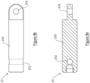
- the operating member may include a pair of parallel shafts 32.
- An example of such a shaft 32 is shown in figure 6 .
- the operating member may include one shaft 32, or more than two (e.g. three, four, five, etc.) shafts 32.
- the operating member is coupled by a link 20 to the adjustor plate 12 and mounted for a range of movements between a fully retracted position, in which the anchor assembly 10 is held adjacent the actuator assembly 30 when the door leaf is in the closed configuration, and an extended position, in which the anchor assembly 10 is in spaced relation to the actuator assembly 30 when the door leaf is in the open configuration.
- the link 20 extends along an axis A-A and the operating member moves in the housing 23 along the axis A-A as the door leaf is opened and closed. It is to be appreciated, therefore, that the direction of the axis A-A changes as the door leaf is pivoted; the direction of the axis A-A moves in a horizontal plane as the door leaf is opened and closed.
- the operating member is biased inwardly of the housing 23 towards the retracted or "door closed” configuration, e.g. as described in GB2456508 .
- the actuator assembly 30 may include a damper mechanism (not shown) to regulate the rate of closure of the door leaf relative to the door frame.
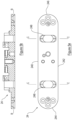
- the adjustor plate 12 may include a first part 12a (shown in figure 2 ) and a second part 12b (shown in figure 3 ). In some embodiments, for example in embodiments where the door closer 1 need not have vertical adjustability, the adjustor plate 12 may be formed as a single part or the adjustor plate 12. In some embodiments (not shown) the adjustor plate 12 may include more than two separable parts.
- the first part 12a of the adjustor plate 12 may include a first pair of facing edges 120a, 122a and a second pair of facing edges 124a, 126a, which connect the first pair of facing edges 120a, 122a to one another.
- the first pair of facing edges 120a, 122a may be longer than the second pair of facing edges 124a, 126a.
- the first pair of facing edges 120a, 122a lies substantially in or parallel to an axis B-B which is at 90° relative to the axis A-A.
- the first part 12a may also be provided with one or more aperture(s) 128a, 129a, e.g. one aperture 128a may be located adjacent each of the second pair of facing edges 124a, 126a.
- One or more of the aperture(s) 128a, 129a may be threaded.
- the second part 12b of the adjustor plate 12 may include a first pair of facing edges 120b, 122b and a second pair of facing edges 124b, 126b, which connect the first pair of facing edges 120b, 122b to one another.
- the first pair of facing edges 120b, 122b may be longer than the second pair of facing edges 124b, 126b.
- the second part 12b is orientated relative to the first part 12a such that the first pair of facing edges 120b, 122b lies substantially in or parallel to the axis B-B.
- the second part 12b may be provided with one or more aperture(s) 128b, which align with the aperture(s) 128a of the first part 12a.
- the second part 12b may be provided with aperture 129b, which may be threaded.
- the second part 12b may have formed therein one or more aperture(s) 121b, which may be threaded.
- the embodiment shown in figure 3 has four apertures 121b, although it is to be appreciated that other embodiments (not shown) may have fewer or more than four apertures 121b without departing from the scope of the invention.
- the frame mounting plate 11 may include a first pair of facing edges 110, 112 and a second pair of facing edges 114, 116, which connect the first pair of facing edges 110, 112 to one another.
- the first pair of facing edges 110, 112 may be longer than the second pair of facing edges 114, 116.
- the frame mounting plate 11 is orientated relative to the adjustor plate 12 such that the first pair of facing edges 110, 112 lies substantially in or parallel to the axis B-B.
- the frame mounting plate 11 may be provided with one or more slot(s) 118, which align with the apertures 128a, 128b of the respective first and second parts 12a, 12b.
- the frame mounting plate 11 may be provided with apertures to receive fixing screws 2 for fixing the anchor assembly 10 to the frame.
- the frame mounting plate 11 may be provided with apertures to receive fixing screws 3 for fixing a cover plate 40 thereto.
- the purpose of the cover plate 40 is primarily to improve the aesthetic appearance of the door closer 1.
- the frame mounting plate 11 may include one or more slot(s) 111 which, in use, align substantially with the aperture(s) 121b of the second part 12b.
- the frame mounting plate 11 may include a slot 119 which, in use, aligns with aperture 129b of the second part 12b.
- the slot(s) 111, 118, 119 may be elongated and extend in the direction of the axis B-B.
- the door leaf mounting plate 24 may include a first pair of facing edges 240, 242 and a second pair of facing edges 244, 246, which connect the first pair of facing edges 240, 242 to one another.
- the first pair of facing edges 240, 242 may be longer than the second pair of facing edges 244, 246.
- the door leaf mounting plate 24 may be provided with apertures to receive fixing screws 2 for fixing the housing 23 within the door leaf.
- the first pair of facing edges 240, 242 of the door leaf mounting plate 24 lies substantially in or parallel to the axis B-B.
- the door leaf mounting plate 24 may be provided with apertures to receive fixing screws 3 for fixing a cover plate 40 thereto.
- the purpose of the cover plate 40 is primarily to improve the aesthetic appearance of the door closer 1.
- the door leaf mounting plate 24 may be provided with one or more slot(s) 248, which, when the frame mounting plate 11 and the door leaf mounting plate 24 are fitted to the respective door frame and door leaf, align substantially with the slot(s) 118 of the frame mounting plate 11.
- the or each slot 248 may be elongated along an axis C-C, the axis C-C being at 90° relative to the axis B-B. It is to be appreciated that the axis C-C is also at 90° relative to the axis A-A. In other words, the or each slot 248 may extend between the facing edges 240, 242 of the door leaf mounting plate 24.
- the shaft 32 may include a first linking member 324, e.g. in the form of a drilled hole, at or adjacent the first end 320 thereof.
- the first linking member 324 is for connecting the shaft 32 to components of the operating member located within the housing 23.
- the shaft 32 may include a second linking member 326, e.g. in the form of a drilled hole, at or adjacent the second end 322 thereof.
- the second linking member 324 is for pivotably connecting the shaft 32 to a link 20.
- a link 20 having a body 200 provided at each end with respective linking members 202, 204, e.g. in the form of drilled holes.
- the link 20 may be in the form of a rod-like member (as shown in the figures).
- the link 20 may take other forms such as that of a plate-like member or a chain.
- the embodiments shown in the figures have two links 20 but in other embodiments fewer (e.g. one) or more (e.g. three, four, five, etc.) links 20 may be provided.
- the or each link 20 may have a length of less than approximately 40 mm.
- the or each link 20 may have a length of approximately 35 mm ⁇ 2 mm.
- the link 20 may have a length of approximately 40 mm or greater, e.g. 45 mm ⁇ 2 mm.
- the or each link 20 may be pivotably connected to the adjustor plate 12 through the slots 118 of the frame mounting plate 11.
- the adjustor plate 12 may include one or more transvers pin(s) 21, to which the or each link 20 may be pivotably connected.
- transverse pin 21 having a body 210 provided at each end with respective linking members 212, 214, e.g. in the form of drilled holes.
- each shaft 32 (not visible since they are accommodated within the housing 23) is pivotably connected to one end 204 of a respective link 20, e.g. by a pin, so that each shaft 32 can pivot relative to its respective link 20.
- the end 202 of each link 20 is connected to the adjustor plate 12.
- the end 202 of each link 20 may be connected to the adjustor plate 12 by the respective transverse pin 21.
- the or each transverse pin 21 may be fixed to the first part 12a of the adjustor plate 12 and pass through apertures 128b and slots 118 of the respective second part 12b and frame mounting plate 11, such that the or each transverse pin 21 extends through the thickness of the second part 12b and frame mounting plate 11.
- the or each transverse pin 21 may be formed integrally with the first part 12a and/or the second part 12b.
- an adjustment member for example an adjusting screw 13 extends through the aperture 129b of the second part 12b and is engaged in the aperture 129a of the first part 12a of the adjustor plate 12. It is to be appreciated that the adjusting screw 13 passes through the slot 119 of the frame mounting plate 11. Rotation of the adjusting screw 13 varies the distance between the frame mounting plate 11 and the adjustor plate 12 in a manner known in the art.
- fasteners 14 may be provided which engage with the respective apertures 121b of the second part 12b. It is to be appreciated that the fasteners 14 pass through the slots 111 of the frame mounting plate 11.
- the door closer 1 is such that a door leaf to which the actuator assembly 30 is mounted can be raised and lowered relative to a door frame to which the frame mounting plate 11 is fixed when the door leaf is hinged to the door frame.
- a door leaf may be raised or lowered whilst being hinged to a door frame and fitted with a door closer 1 according to an embodiment of the invention.
- the hinge(s) connecting the door leaf and door frame must be vertically adjustable when in situ, but may have a variable pivot axis (e.g. a concealed hinge) or a fixed pivot axis (e.g. a butt hinge).
- Figure 9a shows a door closer 1 in a first configuration which corresponds to a door leaf to which the actuator assembly 30 is mounted being set at its maximum raised position relative to a door frame to which the frame mounting plate 11 is fixed.
- Figure 9b shows the door closer 1 in a second configuration which corresponds to the door leaf being set at its maximum lowered position relative to the door frame.
- the fasteners 14 are loosened, so that the adjustor plate 12 can be moved relative to the frame mounting plate 11 along the axis B-B.
- the actuator assembly 30 (and door leaf to which it is mounted) can be moved along the axis B-B relative to the frame mounting plate 11 (and door frame to which it is fixed).
- An advantage of this aspect of the invention is that the links 20 and shafts 32 do not become skewed out of the horizontal plane as the door leaf is raised or lowered relative to the door frame. Instead, as can be seen from figures 9a and 9b , the links 20 (and hence respective shafts 32) remain in the horizontal plane when the actuator assembly 30 is set at its maximum raised position ( figure 9a ) and maximum lowered position ( figure 9b ) relative to the frame mounting plate 11, or any position in between the maximum raised and maximum lowered positions. Consequently, door closers 1 according to this aspect of the invention can be used with door systems fitted with hinges that are vertically adjustable when the door leaf and door frame are fixed to one another. The provision of the slots 111, 118, 119 means that the adjustor plate 12 (and hence actuator assembly 30 to which it is connected) can be moved relative to the frame mounting plate 11 which, in turn, can prolong the lifespan of the door closer 1 and also the hinges themselves.
- the provision of the slot 119 has the further advantage that, if desired, it is possible to retain the feature of the adjusting screw 13 for varying the distance between the frame mounting plate 11 and the adjustor plate 12. It is to be appreciated that without the slot 119 it would not be possible to move the adjustor plate 12 along the axis B-B relative to the frame mounting plate 11 and have the ability to vary the distance between the frame mounting plate 11 and adjustor plate 12. It is also to be appreciated that in order for the door closer 1 to exhibit adjustability along the axis B-B and the ability to vary the distance between the frame mounting plate 11 and adjustor plate 12 the adjustor plate 12 must be formed into at least two separate parts 12a, 12b.
- the adjusting screw 13 is engaged with the first part 12a to permit variation in the distance between the frame mounting plate 11 and adjustor plate 12 and the fasteners 14 are engaged with the second part 12b to permit adjustability along or parallel to the axis B-B. This is adjustability enables the door leaf to be adjusted relative to the door frame vertically, i.e. in a direction parallel to the second axis (B-B).
- the life of the door closer 1 and/or the door hinges can be prolonged.
- a further beneficial feature of the invention is the fact that the slots 248 extend along the axis C-C. Since the axis C-C is at 90° relative to the axis A-A there is an additional effect that neither the link 20 nor its respective shaft 32 come into contact with the door leaf mounting plate 24 as the door leaf pivots about the door frame towards its open configuration. Consequently, the life of the door closer 1 may be further prolonged.
- the adjustor plate 12 includes separate first and second parts 12a, 12b
- first and second parts 12a, 12b may be omitted. Therefore, features described in relation to the first part 12a may be provided on the second part 12b, and vice versa.
Landscapes
- Engineering & Computer Science (AREA)
- Mechanical Engineering (AREA)
- Hinges (AREA)
Claims (14)
- Türschließer (1), umfassend:Eine Ankeranordnung (10), umfassend:
Eine Rahmenmontageplatte (11), die sich relativ zu einem Türrahmen fixieren lässt; und
eine Einstellplatte (12); undeine Betätigungsanordnung (30) zur Montage innerhalb der Dicke eines Türblattes, um das Türblatt zwischen einer offenen und einer geschlossenen Konfiguration relativ zum Türrahmen zu bewegen, wobei die Betätigungsanordnung (30) ein Betätigungselement umfasst, das über eine Verbindung (20) mit der Einstellplatte (12) verbunden ist und für einen Bewegungsbereich zwischen einer vollständig eingefahrenen Position, in der die Ankeranordnung (10) neben der Betätigungsanordnung (30) gehalten wird, wenn sich das Türblatt in der geschlossenen Konfiguration befindet, und einer ausgefahrenen Position, in der die Ankeranordnung (10) in beabstandeter Beziehung zur Ankeranordnung (30) gelagert ist, wenn sich das Türblatt in der offenen Konfiguration befindet, wobei die Verbindung (20) so konfiguriert ist, dass sie sich von der Einstellplatte (12) entlang einer ersten Achse erstreckt, wobei die Rahmenmontageplatte (11) mit einem oder mehreren Schlitz(en) (111, 118, 119) versehen ist, wobei der oder jeder Schlitz (111, 118, 119) in vertikaler Richtung entlang einer zweiten Achse (B-B) verläuft, die im Allgemeinen orthogonal zur ersten Achse ist, wobei die Einstellplatte (12) einen ersten Teil (12a) und einen zweiten Teil (12b) umfasst, wobei der erste Teil (12a) an einem Türrahmen befestigt werden kann und der zweite Teil (12b) an die Rahmenmontageplatte (11) befestigt werden kann, wobei einer des ersten Teils (12a) und des zweiten Teils (12b) eine Öffnung (129a, 129b) zur Aufnahme eines Einstellelements umfasst, mit dem der Abstand zwischen der Rahmenmontageplatte (11) und der Einstellplatte (12) variiert werden kann, und wobei einer der ersten (12a) und der zweiten Teile (12b) eine Formation umfasst, welche die Einstellung der Position des Türblattes relativ zum Türrahmen in einer Richtung parallel zur zweiten Achse (B-B) ermöglicht. - Türschließer (1) nach Anspruch 1, der mehr als eine Verbindung (20) umfasst.
- Türschließer (1) nach Anspruch 1 oder Anspruch 2, wobei die oder jede Verbindung (20) eine Länge von weniger als etwa 40 mm aufweist.
- Türschließer (1) nach irgendeinem vorhergehenden Anspruch, wobei die oder jede Verbindung (20) die Form eines stabförmigen Elements hat.
- Türschließer (1) nach irgendeinem vorhergehenden Anspruch, wobei die oder jede Verbindung (20) schwenkbar mit der Einstellplatte (12) verbunden ist.
- Türschließer (1) nach irgendeinem vorhergehenden Anspruch, wobei die Einstellplatte (12) einen oder mehrere transversale Stift(e) (21) umfasst.
- Türschließer (1) nach Anspruch 6, wobei der oder jeder transversale Stift (21) durch einen der ausgewählten Schlitze (111, 118, 119) der Rahmenmontageplatte (11) verläuft, sodass sich der oder jeder transversale Stift (21) durch die Dicke der Rahmenmontageplatte (11) erstreckt.
- Türschließer (1) nach irgendeinem vorhergehenden Anspruch, der ein oder mehrere Befestigungselemente (14) umfasst, die durch die entsprechenden Schlitze (111, 118, 119) der Rahmenmontageplatte (11) verlaufen und in die entsprechenden Öffnungen (121b, 129a, 129b) der Einstellplatte (12) eingreifen.
- Türschließer (1) nach Anspruch 8, wobei das oder jedes Befestigungselement (14) eine Stellschraube (13) umfasst, wobei die Stellschraube (13) drehbar ist, um den Abstand zwischen der Rahmenmontageplatte (11) und der Einstellplatte (12) zu variieren.
- Türschließer (1) nach irgendeinem vorhergehenden Anspruch, der eine Türblattmontageplatte (24) umfasst, die mit einem oder mehreren Schlitz(en) (248) versehen ist, wobei der oder jeder Schlitz (248) entlang einer dritten Achse (C-C) verlängert ist, wobei die dritte Achse (C-C) im Allgemeinen orthogonal zur ersten Achse (A-A) und im Allgemeinen orthogonal zur zweiten Achse (B-B) ist.
- Türschließer (1) nach irgendeinem vorhergehenden Anspruch, wobei die Betätigungsanordnung (30) einen Dämpfungsmechanismus umfasst, der operativ mit dem Betätigungselement verbunden ist, um die Bewegung des Betätigungselements zumindest dann zu dämpfen, wenn es in Richtung der vollständig eingefahrenen Position bewegt wird.
- Türschließer (1) nach irgendeinem vorhergehenden Anspruch, wobei der erste Teil (12a) der Einstellplatte (12) die Öffnung (129a) zur Aufnahme des Einstellelements umfasst, und der zweite Teil (12b) der Einstellplatte (12) die Formation umfasst, die das Einstellen des Türblattes relativ zum Türrahmen in eine Richtung parallel zur zweiten Achse (B-B) ermöglicht.
- Türschließer (1) nach irgendeinem vorhergehenden Anspruch, wobei die Formation, welche das Einstellen des Türblattes relativ zum Türrahmen in eine Richtung parallel zur zweiten Achse (B-B) ermöglicht, mindestens einen länglichen Schlitz (111, 118, 119) umfasst, in den ein Befestigungselement (14) eingreifen kann.
- Türsystem, das einen Türschließer (1) nach irgendeinem der vorhergehenden Ansprüche umfasst.
Applications Claiming Priority (2)
| Application Number | Priority Date | Filing Date | Title |
|---|---|---|---|
| GB1702330.0A GB2559613B (en) | 2017-02-13 | 2017-02-13 | Door closers |
| PCT/GB2018/050394 WO2018146496A1 (en) | 2017-02-13 | 2018-02-13 | Door closers |
Publications (2)
| Publication Number | Publication Date |
|---|---|
| EP3580419A1 EP3580419A1 (de) | 2019-12-18 |
| EP3580419B1 true EP3580419B1 (de) | 2025-06-18 |
Family
ID=58461938
Family Applications (1)
| Application Number | Title | Priority Date | Filing Date |
|---|---|---|---|
| EP18714009.0A Active EP3580419B1 (de) | 2017-02-13 | 2018-02-13 | Türschliesser |
Country Status (6)
| Country | Link |
|---|---|
| US (1) | US10927580B2 (de) |
| EP (1) | EP3580419B1 (de) |
| CN (1) | CN110573690A (de) |
| CA (1) | CA3053230A1 (de) |
| GB (1) | GB2559613B (de) |
| WO (1) | WO2018146496A1 (de) |
Families Citing this family (3)
| Publication number | Priority date | Publication date | Assignee | Title |
|---|---|---|---|---|
| CN111734246A (zh) * | 2020-08-05 | 2020-10-02 | 宁波市五角阻尼股份有限公司 | 一种闭门器 |
| GB2600424B (en) * | 2020-10-27 | 2023-08-23 | Galeid Ltd | Door closer |
| CN112922481B (zh) * | 2021-02-09 | 2022-01-18 | 广东名门锁业有限公司 | 一种门合页缓冲装置以及包含其的门合页 |
Family Cites Families (16)
| Publication number | Priority date | Publication date | Assignee | Title |
|---|---|---|---|---|
| US370468A (en) * | 1887-09-27 | Chaeles e | ||
| US642691A (en) * | 1899-01-09 | 1900-02-06 | Nathanael C Barnes | Spring-hinge. |
| US686025A (en) * | 1901-02-08 | 1901-11-05 | Samuel H Ramsey | Door-hinge. |
| US959001A (en) * | 1909-10-15 | 1910-05-24 | Julius Tritsch | Hinge. |
| GB2044840B (en) | 1979-03-20 | 1982-11-03 | Perkins & Powell Ltd | Door closer |
| US5170530A (en) * | 1988-03-10 | 1992-12-15 | Reilor Limited | Door closer |
| US5016317A (en) * | 1990-05-14 | 1991-05-21 | Hung Sheng Hu | Lightly-operating automatic door closer with double cylinders |
| GB9416376D0 (en) * | 1994-08-12 | 1994-10-05 | Heath Samuel & Sons Plc | Door closers and dampers primarily for door closers |
| GB0102610D0 (en) * | 2001-02-02 | 2001-03-21 | Heath Samuel & Sons Plc | A door closer |
| US6871381B1 (en) * | 2003-05-28 | 2005-03-29 | Door closure with adjusting mechanism for controlling door closing speed | |
| RU2386773C2 (ru) | 2005-04-26 | 2010-04-20 | СУСПА Холдинг ГмбХ | Шарнирное устройство |
| GB2456508B (en) * | 2008-01-15 | 2012-11-28 | Heath Samuel & Sons Plc | Door closer |
| CN201513043U (zh) | 2009-10-23 | 2010-06-23 | 广东中侨五金电器制造有限公司 | 家具门用的缓冲铰链 |
| GB2506099B (en) | 2012-07-06 | 2015-09-16 | Artco Watch Embryo Factory Ltd | Damped hinge |
| CN106232922B (zh) * | 2014-03-25 | 2018-01-16 | Ol.Mi有限公司 | 液压铰链,尤其用于门的隐藏式铰链 |
| CN109477351B (zh) * | 2016-06-10 | 2020-03-06 | 安塞尔米有限责任公司 | 用于自动关闭门的装置 |
-
2017
- 2017-02-13 GB GB1702330.0A patent/GB2559613B/en active Active
-
2018
- 2018-02-13 WO PCT/GB2018/050394 patent/WO2018146496A1/en not_active Ceased
- 2018-02-13 CN CN201880025064.3A patent/CN110573690A/zh active Pending
- 2018-02-13 EP EP18714009.0A patent/EP3580419B1/de active Active
- 2018-02-13 CA CA3053230A patent/CA3053230A1/en active Pending
- 2018-02-13 US US16/485,266 patent/US10927580B2/en active Active
Also Published As
| Publication number | Publication date |
|---|---|
| US10927580B2 (en) | 2021-02-23 |
| GB2559613B (en) | 2022-04-20 |
| GB201702330D0 (en) | 2017-03-29 |
| CA3053230A1 (en) | 2018-08-16 |
| CN110573690A (zh) | 2019-12-13 |
| US20190383082A1 (en) | 2019-12-19 |
| WO2018146496A1 (en) | 2018-08-16 |
| GB2559613A (en) | 2018-08-15 |
| EP3580419A1 (de) | 2019-12-18 |
Similar Documents
| Publication | Publication Date | Title |
|---|---|---|
| US5511287A (en) | Furniture hinge | |
| US11542738B2 (en) | Door closers | |
| US5727289A (en) | Hinge mounted adjustable door stop | |
| BR112020008670A2 (pt) | ferragem para porta de abertura de móvel, parede lateral para um corpo de móvel e móvel com um corpo de móvel e uma porta de abertura guiada | |
| CA2332484A1 (en) | Adjustable hinge | |
| EP3580419B1 (de) | Türschliesser | |
| EP2732117A1 (de) | Drehflügelbetätiger-gestängearm | |
| CN211448232U (zh) | 一种窗用重型滑撑 | |
| US4368558A (en) | Door hinge with a pressure closing device | |
| CN101435300A (zh) | 能够不用工具地安装的角部铰链 | |
| RS61369B1 (sr) | Skrivena šarka | |
| JP5358042B2 (ja) | 隠し丁番 | |
| HK1252743A1 (en) | Door closers | |
| CN211923884U (zh) | 枢转结构及包含该枢转结构的柜子、窗和门 | |
| CA3020835C (en) | End load arm | |
| US12398587B1 (en) | Window hinge assembly and methods | |
| EP2172609B1 (de) | Automatische Vorrichtung zum Sperren von Türblättern oder Fenstern und dergleichen | |
| PL215456B1 (pl) | Czesc zawiasu do drzwi, okien i temu podobnych | |
| US5107570A (en) | Intermediate bearing for door or window | |
| CN219509459U (zh) | 一种窗用摩擦铰链及窗户 | |
| RU2775117C2 (ru) | Фурнитура створки для предмета мебели, боковая стенка корпуса мебели и предмет мебели, имеющий боковую стенку | |
| CN221298894U (zh) | 一种铰链 | |
| RU2083790C1 (ru) | Шарнирная петля для створки двери | |
| EP3971377B1 (de) | Scharnier, rahmenpaneelanordnung zum schliessen einer öffnung und verfahren zum einstellen einer rahmenpaneelanordnung | |
| AU2010201658B2 (en) | Adjustable hinge assembly and method of adjustment |
Legal Events
| Date | Code | Title | Description |
|---|---|---|---|
| STAA | Information on the status of an ep patent application or granted ep patent |
Free format text: STATUS: UNKNOWN |
|
| STAA | Information on the status of an ep patent application or granted ep patent |
Free format text: STATUS: THE INTERNATIONAL PUBLICATION HAS BEEN MADE |
|
| PUAI | Public reference made under article 153(3) epc to a published international application that has entered the european phase |
Free format text: ORIGINAL CODE: 0009012 |
|
| STAA | Information on the status of an ep patent application or granted ep patent |
Free format text: STATUS: REQUEST FOR EXAMINATION WAS MADE |
|
| 17P | Request for examination filed |
Effective date: 20190912 |
|
| AK | Designated contracting states |
Kind code of ref document: A1 Designated state(s): AL AT BE BG CH CY CZ DE DK EE ES FI FR GB GR HR HU IE IS IT LI LT LU LV MC MK MT NL NO PL PT RO RS SE SI SK SM TR |
|
| AX | Request for extension of the european patent |
Extension state: BA ME |
|
| DAV | Request for validation of the european patent (deleted) | ||
| DAX | Request for extension of the european patent (deleted) | ||
| STAA | Information on the status of an ep patent application or granted ep patent |
Free format text: STATUS: EXAMINATION IS IN PROGRESS |
|
| 17Q | First examination report despatched |
Effective date: 20231108 |
|
| GRAP | Despatch of communication of intention to grant a patent |
Free format text: ORIGINAL CODE: EPIDOSNIGR1 |
|
| STAA | Information on the status of an ep patent application or granted ep patent |
Free format text: STATUS: GRANT OF PATENT IS INTENDED |
|
| INTG | Intention to grant announced |
Effective date: 20250109 |
|
| GRAS | Grant fee paid |
Free format text: ORIGINAL CODE: EPIDOSNIGR3 |
|
| GRAA | (expected) grant |
Free format text: ORIGINAL CODE: 0009210 |
|
| STAA | Information on the status of an ep patent application or granted ep patent |
Free format text: STATUS: THE PATENT HAS BEEN GRANTED |
|
| AK | Designated contracting states |
Kind code of ref document: B1 Designated state(s): AL AT BE BG CH CY CZ DE DK EE ES FI FR GB GR HR HU IE IS IT LI LT LU LV MC MK MT NL NO PL PT RO RS SE SI SK SM TR |
|
| REG | Reference to a national code |
Ref country code: GB Ref legal event code: FG4D |
|
| REG | Reference to a national code |
Ref country code: CH Ref legal event code: EP |
|
| REG | Reference to a national code |
Ref country code: DE Ref legal event code: R096 Ref document number: 602018082644 Country of ref document: DE |
|
| REG | Reference to a national code |
Ref country code: CH Ref legal event code: EP |
|
| REG | Reference to a national code |
Ref country code: IE Ref legal event code: FG4D |
|
| P01 | Opt-out of the competence of the unified patent court (upc) registered |
Free format text: CASE NUMBER: UPC_APP_0786_3580419/2025 Effective date: 20250722 |
|
| PG25 | Lapsed in a contracting state [announced via postgrant information from national office to epo] |
Ref country code: FI Free format text: LAPSE BECAUSE OF FAILURE TO SUBMIT A TRANSLATION OF THE DESCRIPTION OR TO PAY THE FEE WITHIN THE PRESCRIBED TIME-LIMIT Effective date: 20250618 |
|
| REG | Reference to a national code |
Ref country code: LT Ref legal event code: MG9D |
|
| PG25 | Lapsed in a contracting state [announced via postgrant information from national office to epo] |
Ref country code: NO Free format text: LAPSE BECAUSE OF FAILURE TO SUBMIT A TRANSLATION OF THE DESCRIPTION OR TO PAY THE FEE WITHIN THE PRESCRIBED TIME-LIMIT Effective date: 20250918 Ref country code: GR Free format text: LAPSE BECAUSE OF FAILURE TO SUBMIT A TRANSLATION OF THE DESCRIPTION OR TO PAY THE FEE WITHIN THE PRESCRIBED TIME-LIMIT Effective date: 20250919 |
|
| PG25 | Lapsed in a contracting state [announced via postgrant information from national office to epo] |
Ref country code: BG Free format text: LAPSE BECAUSE OF FAILURE TO SUBMIT A TRANSLATION OF THE DESCRIPTION OR TO PAY THE FEE WITHIN THE PRESCRIBED TIME-LIMIT Effective date: 20250618 |
|
| PG25 | Lapsed in a contracting state [announced via postgrant information from national office to epo] |
Ref country code: HR Free format text: LAPSE BECAUSE OF FAILURE TO SUBMIT A TRANSLATION OF THE DESCRIPTION OR TO PAY THE FEE WITHIN THE PRESCRIBED TIME-LIMIT Effective date: 20250618 |
|
| PG25 | Lapsed in a contracting state [announced via postgrant information from national office to epo] |
Ref country code: RS Free format text: LAPSE BECAUSE OF FAILURE TO SUBMIT A TRANSLATION OF THE DESCRIPTION OR TO PAY THE FEE WITHIN THE PRESCRIBED TIME-LIMIT Effective date: 20250918 |
|
| REG | Reference to a national code |
Ref country code: NL Ref legal event code: MP Effective date: 20250618 |
|
| PG25 | Lapsed in a contracting state [announced via postgrant information from national office to epo] |
Ref country code: LV Free format text: LAPSE BECAUSE OF FAILURE TO SUBMIT A TRANSLATION OF THE DESCRIPTION OR TO PAY THE FEE WITHIN THE PRESCRIBED TIME-LIMIT Effective date: 20250618 |
|
| PG25 | Lapsed in a contracting state [announced via postgrant information from national office to epo] |
Ref country code: NL Free format text: LAPSE BECAUSE OF FAILURE TO SUBMIT A TRANSLATION OF THE DESCRIPTION OR TO PAY THE FEE WITHIN THE PRESCRIBED TIME-LIMIT Effective date: 20250618 |
|
| PG25 | Lapsed in a contracting state [announced via postgrant information from national office to epo] |
Ref country code: PT Free format text: LAPSE BECAUSE OF FAILURE TO SUBMIT A TRANSLATION OF THE DESCRIPTION OR TO PAY THE FEE WITHIN THE PRESCRIBED TIME-LIMIT Effective date: 20251020 |
|
| REG | Reference to a national code |
Ref country code: AT Ref legal event code: MK05 Ref document number: 1804318 Country of ref document: AT Kind code of ref document: T Effective date: 20250618 |
|
| PG25 | Lapsed in a contracting state [announced via postgrant information from national office to epo] |
Ref country code: IS Free format text: LAPSE BECAUSE OF FAILURE TO SUBMIT A TRANSLATION OF THE DESCRIPTION OR TO PAY THE FEE WITHIN THE PRESCRIBED TIME-LIMIT Effective date: 20251018 |
|
| PGFP | Annual fee paid to national office [announced via postgrant information from national office to epo] |
Ref country code: GB Payment date: 20251203 Year of fee payment: 9 |
|
| PG25 | Lapsed in a contracting state [announced via postgrant information from national office to epo] |
Ref country code: AT Free format text: LAPSE BECAUSE OF FAILURE TO SUBMIT A TRANSLATION OF THE DESCRIPTION OR TO PAY THE FEE WITHIN THE PRESCRIBED TIME-LIMIT Effective date: 20250618 Ref country code: SM Free format text: LAPSE BECAUSE OF FAILURE TO SUBMIT A TRANSLATION OF THE DESCRIPTION OR TO PAY THE FEE WITHIN THE PRESCRIBED TIME-LIMIT Effective date: 20250618 |
|
| PG25 | Lapsed in a contracting state [announced via postgrant information from national office to epo] |
Ref country code: CZ Free format text: LAPSE BECAUSE OF FAILURE TO SUBMIT A TRANSLATION OF THE DESCRIPTION OR TO PAY THE FEE WITHIN THE PRESCRIBED TIME-LIMIT Effective date: 20250618 |
|
| PG25 | Lapsed in a contracting state [announced via postgrant information from national office to epo] |
Ref country code: PL Free format text: LAPSE BECAUSE OF FAILURE TO SUBMIT A TRANSLATION OF THE DESCRIPTION OR TO PAY THE FEE WITHIN THE PRESCRIBED TIME-LIMIT Effective date: 20250618 |
|
| PG25 | Lapsed in a contracting state [announced via postgrant information from national office to epo] |
Ref country code: EE Free format text: LAPSE BECAUSE OF FAILURE TO SUBMIT A TRANSLATION OF THE DESCRIPTION OR TO PAY THE FEE WITHIN THE PRESCRIBED TIME-LIMIT Effective date: 20250618 |
|
| PG25 | Lapsed in a contracting state [announced via postgrant information from national office to epo] |
Ref country code: RO Free format text: LAPSE BECAUSE OF FAILURE TO SUBMIT A TRANSLATION OF THE DESCRIPTION OR TO PAY THE FEE WITHIN THE PRESCRIBED TIME-LIMIT Effective date: 20250618 Ref country code: SK Free format text: LAPSE BECAUSE OF FAILURE TO SUBMIT A TRANSLATION OF THE DESCRIPTION OR TO PAY THE FEE WITHIN THE PRESCRIBED TIME-LIMIT Effective date: 20250618 |
|
| PG25 | Lapsed in a contracting state [announced via postgrant information from national office to epo] |
Ref country code: ES Free format text: LAPSE BECAUSE OF FAILURE TO SUBMIT A TRANSLATION OF THE DESCRIPTION OR TO PAY THE FEE WITHIN THE PRESCRIBED TIME-LIMIT Effective date: 20250618 |
|
| PG25 | Lapsed in a contracting state [announced via postgrant information from national office to epo] |
Ref country code: DK Free format text: LAPSE BECAUSE OF FAILURE TO SUBMIT A TRANSLATION OF THE DESCRIPTION OR TO PAY THE FEE WITHIN THE PRESCRIBED TIME-LIMIT Effective date: 20250618 |
|
| PG25 | Lapsed in a contracting state [announced via postgrant information from national office to epo] |
Ref country code: IT Free format text: LAPSE BECAUSE OF FAILURE TO SUBMIT A TRANSLATION OF THE DESCRIPTION OR TO PAY THE FEE WITHIN THE PRESCRIBED TIME-LIMIT Effective date: 20250618 |
|
| PLBE | No opposition filed within time limit |
Free format text: ORIGINAL CODE: 0009261 |
|
| STAA | Information on the status of an ep patent application or granted ep patent |
Free format text: STATUS: NO OPPOSITION FILED WITHIN TIME LIMIT |