EP3580092B1 - Köpfstütze - Google Patents
Köpfstütze Download PDFInfo
- Publication number
- EP3580092B1 EP3580092B1 EP18709246.5A EP18709246A EP3580092B1 EP 3580092 B1 EP3580092 B1 EP 3580092B1 EP 18709246 A EP18709246 A EP 18709246A EP 3580092 B1 EP3580092 B1 EP 3580092B1
- Authority
- EP
- European Patent Office
- Prior art keywords
- head support
- head
- headrest
- head contact
- region
- Prior art date
- Legal status (The legal status is an assumption and is not a legal conclusion. Google has not performed a legal analysis and makes no representation as to the accuracy of the status listed.)
- Active
Links
Images


Classifications
-
- B—PERFORMING OPERATIONS; TRANSPORTING
- B60—VEHICLES IN GENERAL
- B60N—SEATS SPECIALLY ADAPTED FOR VEHICLES; VEHICLE PASSENGER ACCOMMODATION NOT OTHERWISE PROVIDED FOR
- B60N2/00—Seats specially adapted for vehicles; Arrangement or mounting of seats in vehicles
- B60N2/70—Upholstery springs ; Upholstery
- B60N2/7011—Upholstery springs ; Upholstery of substantially two-dimensional shape, e.g. hammock-like, plastic shells, fabrics
-
- B—PERFORMING OPERATIONS; TRANSPORTING
- B60—VEHICLES IN GENERAL
- B60N—SEATS SPECIALLY ADAPTED FOR VEHICLES; VEHICLE PASSENGER ACCOMMODATION NOT OTHERWISE PROVIDED FOR
- B60N2/00—Seats specially adapted for vehicles; Arrangement or mounting of seats in vehicles
- B60N2/80—Head-rests
- B60N2/888—Head-rests with arrangements for protecting against abnormal g-forces, e.g. by displacement of the head-rest
-
- B—PERFORMING OPERATIONS; TRANSPORTING
- B60—VEHICLES IN GENERAL
- B60N—SEATS SPECIALLY ADAPTED FOR VEHICLES; VEHICLE PASSENGER ACCOMMODATION NOT OTHERWISE PROVIDED FOR
- B60N2/00—Seats specially adapted for vehicles; Arrangement or mounting of seats in vehicles
- B60N2/75—Arm-rests
-
- B—PERFORMING OPERATIONS; TRANSPORTING
- B60—VEHICLES IN GENERAL
- B60N—SEATS SPECIALLY ADAPTED FOR VEHICLES; VEHICLE PASSENGER ACCOMMODATION NOT OTHERWISE PROVIDED FOR
- B60N2/00—Seats specially adapted for vehicles; Arrangement or mounting of seats in vehicles
- B60N2/80—Head-rests
-
- B—PERFORMING OPERATIONS; TRANSPORTING
- B60—VEHICLES IN GENERAL
- B60N—SEATS SPECIALLY ADAPTED FOR VEHICLES; VEHICLE PASSENGER ACCOMMODATION NOT OTHERWISE PROVIDED FOR
- B60N2/00—Seats specially adapted for vehicles; Arrangement or mounting of seats in vehicles
- B60N2/80—Head-rests
- B60N2002/899—Head-rests characterised by structural or mechanical details not otherwise provided for
Definitions
- the invention relates to a headrest for a seat, in particular for a vehicle seat.
- a vehicle in the sense of the invention can be a land, air or water vehicle.
- Land vehicles are, for example, motor vehicles and rail vehicles.
- the headrest comprises a head support device with a head support surface and a bearing device for attachment to a vehicle seat.
- a headrest which comprises a headrest body which can be mounted on a seat using a bearing device.
- the headrest body can be made in one piece from plastic.
- the DE 32 26 149 C2 discloses a headrest in which the headrest part is formed by a bracket which is provided with a foam or a textile covering.
- the GB 2 315 408 A relates to a headrest which has a substantially rigid back plate which is connected to two support rods.
- a plastically deformable material in the form of a deformation part is attached to the back plate in such a way that it can deform in the direction of the back plate in the event of an accident and in doing so absorbs kinetic energy.
- This deformation part can, for example, have several vertically extending fingers between which gaps are formed.
- a filling and padding of the headrest can be provided (see page 5, paragraph 2).
- the DE 695 00 785 T2 relates to a vehicle seat with a headrest and a neckrest that can be attached to the headrest.
- the task was to create an improved neckrest.
- the headrest is mentioned as a holder for the neckrest and is otherwise not discussed in detail.
- the WO 2017/005660 A1 relates to a headrest.
- the headrest comprises a headrest body which has a frame with one or more internal flexible support elements forming a support surface which is formed by primary molding from a plastic material, in particular from a material free of foamed materials, or from a composite material.
- the headrest can be formed in one piece or in multiple pieces.
- the object of the invention was to create a headrest that has a simple structure and is therefore easy to manufacture.
- the headrest comprises a head support device on which a head support area is formed with a head support surface that serves as an abutment for the head of a seat occupant.
- the head support device is held on a bearing device by means of which it is mounted on the seat.
- the head support device is designed as a single piece.
- the head support device is designed as a plastic injection molded part.
- the head support device is manufactured as a non-foamed plastic injection molded part.
- the head support device is manufactured, for example, from one material component or from several material components. If the plastic injection molded part is manufactured from several material components, these are, for example, integrated into a material, as in the case of a fiber composite material, or, as in the case of a two-component injection molding process, e.g. connected to one another in such a way that one part is formed.
- the head support device or the head support area does not form a closed housing, but is designed to be open. In other words, the head support device does not form a closed cavity or interior space.
- the head support area is designed as a plate, in particular as a thin plate with a material thickness of approximately 1.5 mm to 10 mm.
- plate is to be understood as a thin wall; the plate does not have to be flat, but can rather be freely shaped.
- the plate is in particular made of solid material. In particular, the plate is made of unfoamed material.
- the head support area or the entire head support device has free side areas. A lower end area of the head support area is connected to the bearing device.
- the plate has a G-shape.
- the plate in the head support area is essentially vertical and forms a free upper end area.
- the lower end area of the head support area is then curved like a G and runs backwards and back to the head support area.
- the head contact area forms a free end.
- a lower end area of the head contact area is connected to the bearing device.
- the upper end area forms a free end.
- the design of the head contact area with a free end has the advantage that the head contact area can cover a larger spring travel if the free end can be flexibly deformed.
- the head support device is provided with bearing means for fastening the bearing device.
- the bearing means can be designed as receiving seats for support rods or for a support rod bracket, for example.
- the head support device and/or the holding device form an impact surface for the head support area.
- the impact surface represents a limit for the deformation of the head support area.
- the head support device deforms to a certain extent, the head support area comes into contact with the impact surface, which prevents further deformation.
- the head support area of the head support device can be designed and mounted differently.
- the head support area is held firmly to the headrest, in particular to the head support device.
- the head support area for example, has a concave shape, with side areas of the head support area protruding with respect to a vertical central axis.
- the head support device can, for example, have a frame which is assigned to the head support area.
- a covering, a film or another structure is molded onto the frame.
- the structure can, for example, have a deformability or displaceability that is different from that of the frame. While the frame only shifts when a large force is applied due to the deformability of the head support device, the structure can deform even when smaller forces are applied, e.g. to adapt to the head of the seat occupant.
- the covering is, for example, at least partially transparent so that the head support area allows a view to the rear.
- the head support area is provided with an elastic structure.
- the elastic structure is limited by a frame of the head support device and held thereto.
- the structure is elastically deformable so that it gives way elastically when the head is supported.
- the elastic structure is designed such that it can deform relative to the frame.
- the elastic structure can be provided with a different elasticity than the frame of the head support area.
- a film in particular a transparent film, or a net can be attached to the frame.
- the head contact surface is transparent.
- the head contact surface is, for example, assigned to a separate part forming the head contact surface, which is connected to at least one spring on a frame of the head contact device or a frame of the head contact area.
- the plate can then be displaced relative to the frame when a force is applied to the head contact surface, deforming the spring.
- a spring is understood to mean any type of elastically deformable material.
- the headrest area can be provided with at least one opening, in particular with a plurality of openings. If the headrest device is formed by a plate, the plate is provided with openings in the headrest area.
- the headrest area forms a grille, for example. This can ensure a better view to the rear and also ensure better ventilation. This also makes the headrest lighter.
- Fasteners for attaching a soft pad can be provided on the headrest area.
- the soft pad can be made of a cushion, a textile mat or a fleece, for example.
- the soft pad serves to increase the comfort of the seat occupant.
- the headrest device or the entire headrest is formed, for example, from a first relatively hard plastic and has, at least in part, a second soft plastic in the headrest area.
- the second plastic can be produced, for example, using a two-component injection molding process.
- the headrest or the headrest device is molded from hard material, including the headrest area. In the headrest area, the soft material is applied to the hard material.
- the soft component is arranged on the headrest area, facing the seat occupant.
- the soft material can be a silicone plastic, for example, or contain one.
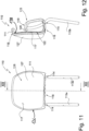
- a headrest according to the first embodiment (see the Fig. 1 to 4 ) as a whole is designated in the figures with the reference number 10. This headrest 10 is not part of the present invention.
- the headrest 10 is formed in one piece.
- the entire headrest 10 is formed as a thin plate, i.e. as a thin wall with a thickness of e.g. 1.5 to 10 mm.
- the plate is formed without foam.
- the plate is formed, for example, from solid material, i.e. it has essentially no air pockets. It can be manufactured, for example, as a plastic injection-molded part. However, other materials, such as metal or composite materials, such as fiber composite materials, are also possible.
- the headrest 10 comprises a head support device 11 and a bearing device 12, which is connected in one piece to the head support device 11.
- the headrest 10 can, for example, be produced in one molding operation.
- the head support device 11 comprises a head support area 17 with a head support surface 16.
- the head support area 17 is provided with a plurality of recesses 13 so that a grid structure is formed.
- the recesses 13 allow, for example, a view through the head support area 17 and result in a saving in material and weight.
- the head support area 17 could also be designed without recesses 13, i.e. as a closed wall.
- the head support device 11 with the head support area 17 is designed as an approximately vertically extending plate which comprises an upper area 20 which forms a free end.
- the head support device 11 is approximately I-shaped and extends, for example, approximately in one plane.
- a lower area 18 of the head support device 11 is connected in one piece to the bearing device 12.
- Side areas 19a and 19b are also freely designed.
- the side areas 19a and 19b jump with respect to a central area which, for example, forms the cutting plane according to Fig.4 so that the head contact surface 16 has a concave shape.
- the entire Headrest including the head support area is made of a rigid material.
- the bearing device 12 is height-adjustable or can be firmly attached to a seat structure of a vehicle seat (not shown).
- the bearing device 12 has a bend 15 in an upper region 14, whereby the head support device 11 is arranged further forward in the direction x1 with respect to the bearing device 12, i.e. closer to the seat occupant, and the transition between the bearing device 12 and the head support device 11 has an S-shape.
- the material of the headrest 10 is, for example, elastically deformable, so that the head support device 11 can be pivoted relative to the bearing device 12 in the direction u1 when a force F acts in the direction x2 on the head support surface 16 of the head support area 17. As soon as the force F is removed, the head support device 11 is returned in the direction u2 to its original shape according to the Fig. 1 to 4
- the free deformability from the Fig.1 to shown position in the direction u1 results from the elastic deformability of the material and from the fact that the side regions 19a and 19b and the upper region 14 are freely formed.
- the embodiment according to the Fig. 1 to 4 has a narrow design, as shown in the side view according to Fig. 2 can be seen.
- the headrest 10 is easy to manufacture because it is a single piece and can be flexibly designed with regard to color and shape.
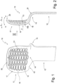
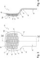
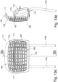
- FIG. 5 to 7 A second embodiment is shown in the Fig. 5 to 7
- the headrest as a whole is designated in the figures by the reference numeral 110.
- the headrest 110 comprises a head support device 111 which forms a separate part, as well as a bearing device 112.
- the bearing device 112 comprises support rods 113a and 113b which are firmly connected to the head support device 111.
- the support rods 113a and 113b each have a lower end region 135 which can be mounted on a vehicle seat (not shown) either firmly or with height adjustment in the direction z1 and z2.
- a support rod bracket could also be used.
- the bearing device 112 could have a region which can be manufactured in one piece - e.g. from plastic injection molding - with the head support device 111 and which can be mounted on the vehicle seat.
- the head support device 111 comprises a bearing area 115 and a head support area 116 with a head support surface 117.
- the head support device 111 is formed from a foam-free plate. It is made of solid material.
- the head support surface 117 is concave with respect to a vertical central axis, ie side areas protrude with respect to a central area. In the side view according to Fig.6 the head support device 111 has approximately a G-shape or spiral shape.
- the head support device 111 In a lower region 118, the head support device 111 has openings 114 through which the support rods 113a and 113b pass.
- the openings 114 each form a bearing for supporting the head support device 111.
- An upper end of the support rods 113a and 113b is firmly connected by a fastening 121 to a section 119 of the bearing region 115 running back in the direction of the head support region 116.
- the bearing area 115 is shaped like a clamp and comprises the approximately horizontal lower area 118, the section 119 which also runs approximately horizontally, and an approximately vertical area 136.
- the section 119 comprises an impact surface 120 which forms a stop for the head contact area 116 when the latter pivots in the direction w1 due to deformation when a force F acts on the head contact surface 117.
- the head support region 116 forms a free end 125.
- side regions 137a and 137b of the head support region 116 are also freely formed.
- the head support device 111 is designed to be flexible in such a way that the head support region 116, in particular a frame 126 of the head support region 116, is elastically deformable relative to the bearing region 115, in particular pivotable in the directions w1 and w2 when the force F acts on the head support surface 117.
- the head support region 116 pivots back in the direction w2.
- the head support region 116 merges into the lower region 118.
- the head contact area 116 is provided with a resilient structure 122.
- the structure 122 is connected to the frame 126.
- the structure 122 comprises surface areas 123 which are connected to at least one other surface area 123 by means of at least one S-shaped web 124.
- the webs 124 are elastically bendable and can be twisted. Due to the shape of the webs 124, a large spring travel can be achieved even when using a rigid material due to the accumulation of the elastic deformations of the webs 124.
- the structure 122 can therefore move from a Fig.6 shown basic shape in direction x2 and when the force F decreases, it deforms back to the original shape in direction x1.
- structure 122 reference is made to the application with the file number EN 10 2017 129 831.2 .
- a film in particular a transparent film, or a net can be held on the frame 126 instead of the structure 122. In this way, the head contact surface is transparent.
- the headrest 110 shown corresponds to the headrest shown in the Fig. 5 to 7 illustrated headrest 110, the only difference being that the head support surface 117 is provided with a cushion 127.
- the head support surface 117 is therefore only an indirect head support, since the head of the seat occupant rests on the cushion 127.
- the cushion 127 has the advantage that forces acting on the head support surface 117 are distributed by the cushion 127.
- the cushion makes the head support more comfortable.
- the cushion 127 is advantageous from a hygienic point of view because it can be detachably attached to the head support device and can therefore be cleaned.
- the cushion 127 can be combined with all embodiments of headrests 10, 110, 210 and 310 of this application.
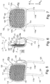
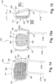
- the Fig. 13a to 13e illustrated headrest 110 corresponds to the headrest 110 according to the Fig. 5 to 7 , wherein the head support region 116 is not provided with the resilient structure 122, but is essentially non-deformable, i.e. rigid, relative to the frame 126 of the head support region 116.
- the frame of the head support region 116 is movable relative to the bearing region 115 due to the deformability of the head support device 111.
- the head support region 116 comprises recesses 128, so that a grid structure is formed.
- the head contact area 116 comprises in this embodiment, a separate, essentially rigid spring part 129, which forms the head contact surface 117.
- the spring part 129 is attached by means of a membrane 130 to a reveal 138 of a recess 131 formed in the head contact area 116, which is formed by the frame 126.
- the membrane can be formed from any elastically deformable material. It is formed, for example, from a rubber-like material.
- the spring part 129 can also be connected to the head contact area 116 by means of individual springs distributed over the circumference.
- the spring part 129 Under the action of a force F on the head contact surface 117, the spring part 129 is initially moved in the direction x2 with elastic deformation of the membrane 130 until an edge surface 132 of the spring part 129 strikes a stop surface 133 of the head contact device 111 (see Fig. 25 ). If a large force F is applied, the entire head contact area 116 with the frame could be displaced after the stop described above until a rear surface 134 of the spring part 129 strikes the impact surface 120. Due to the elastic restoring force, the head contact area 116 and the spring part 129 return to the starting position according to Fig. 24 a.
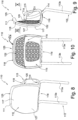
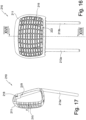
- the headrest 210 comprises a head support device 211 in the form of a separate part, which can be mounted on a vehicle seat with a bearing device 212 so that it is height-adjustable or fixed.
- the bearing device 212 comprises support rods 213a, 213b, which are firmly connected to the head support device 211.
- the support rods 213a and 213b are mounted on a vehicle seat so that they are height-adjustable or fixed.
- a support rod bracket could also be used.
- the bearing device 212 could have a region which can be manufactured in one piece - e.g. from plastic injection molding - with the head support device 211 and which can be mounted on the vehicle seat.
- the head support device 211 is designed in accordance with Fig. 15 shown side view, it is approximately O-shaped and has an overall approximately tubular or sleeve-shaped design.
- the head support device 211 has a head support region 214 with a head support surface 215 and a bearing region 216.
- the head support region 214 is made without foam and is made of a solid material.
- the bearing region 216 comprises recesses 217 through which the support rods 213a and 213b pass, as well as receiving seats 218 in which upper end regions 219 of the support rods 213a and 213b are received and fastened.
- the head support device 211 has recesses 220a and 220b on the sides and a rear recess 221 in the bearing area 216.
- the head support area 214 is provided with recesses 222 so that a grid is formed.
- the material of the head support device 211 is essentially non-deformable.
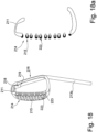
- the Fig. 18 and 18a The headrest 210 shown is not part of the present invention. It corresponds to the headrest 210 of the Fig. 14 to 17 , the head support surface 215 being provided with a soft component 223, which ensures a comfortable support for the seat occupant.
- the soft component 223 can be formed from a silicone, for example.
- the soft component 223 can be manufactured together with the head support device 211, for example using a 2-component injection molding process. As shown in Fig. 23 As can be seen, the soft component 223 encompasses the webs of the head contact area 214 formed by the recesses 222 up to a reveal of the recess 222.
Landscapes
- Engineering & Computer Science (AREA)
- Aviation & Aerospace Engineering (AREA)
- Transportation (AREA)
- Mechanical Engineering (AREA)
- Seats For Vehicles (AREA)
- Chair Legs, Seat Parts, And Backrests (AREA)
Description
- Die Erfindung betrifft eine Kopfstütze für einen Sitz, insbesondere für einen Fahrzeugsitz. Ein Fahrzeug kann im Sinne der Erfindung ein Land-, Luft- oder Wasserfahrzeug sein. Landfahrzeuge sind z.B. Kraftfahrzeuge und Schienenfahrzeuge. Die Kopfstütze umfasst eine Kopfanlagevorrichtung mit einer Kopfanlagefläche sowie eine Lagervorrichtung zur Halterung an einem Fahrzeugsitz.
- Aus der
DE 10 2015 212 510 A1 ist eine Kopfstütze bekannt, die einen Kopfstützenkörper umfasst, welcher mit einer Lagervorrichtung an einem Sitz lagerbar ist. Der Kopfstützenkörper kann einteilig aus Kunststoff hergestellt sein. - Die
DE 32 26 149 C2 offenbart eine Kopfstütze, bei welcher das Kopfanlageteil von einem Bügel gebildet ist, welcher mit einem Schaum, oder einer textilen Bespannung versehen ist. - Aus der
US 2005/0127735 A1 ist ein Sitz mit einer Kopfstütze bekannt, wobei die Kopfstütze einen Träger umfasst, an welchen ein elastisches Material angeformt ist. - Die
GB 2 315 408 A - Die
US 2011/133531 A1 beschreibt einen Fahrzeugsitz mit einem Lehnenteil und einem Sitzteil wobei das Lehnenteil und das Sitzteil derart aufgebaut sind, dass zwischen einem unteren und einem oberen Rahmen ein Gewebe eingeklemmt wird. Auf diese Weise soll das Gewicht des Fahrzeugs reduziert werden und die Belüftung des Sitzinsassen verbessert werden. Eine Kopfstütze ist kurz erwähnt (siehe Ende Absatz 18), aber nicht näher beschrieben. - Die
DE 695 00 785 T2 betrifft einen Fahrzeugsitz mit einer Kopfstütze und einer an der Kopfstütze befestigbaren Nackenstütze. Die Aufgabenstellung bestand darin, eine verbesserte Nackenstütze zu schaffen. In dieser Druckschrift wird die Kopfstütze als Halterung für die Nackenstütze erwähnt und ansonsten nicht detailliert darauf eingegangen. - Die
WO 2017/005660 A1 betrifft eine Kopfstütze. Die Kopfstütze umfasst einen Kopfstützenkörper, welcher einen Rahmen mit einem oder mehreren innenliegenden, eine Auflagefläche bildenden flexiblen Auflageelementen aufweist, die durch Urformen aus einem Kunststoffmaterial, insbesondere aus einem Werkstoff frei von aufgeschäumten Materialien, oder aus einem Verbundwerksstoff gebildet ist. Die Kopfstütze kann einteilig oder mehrteilig ausgebildet sein. - Es war Aufgabe der Erfindung eine Kopfstütze zu schaffen, die einfach einen einfachen Aufbau besitzt und damit einfach herstellbar ist.
- Die Aufgabe wird gelöst durch eine Kopfstütze mit den Merkmalen des Anspruchs 1.
- Die Kopfstütze umfasst eine Kopfanlagevorrichtung, an welchem ein Kopfanlagebereich mit einer Kopfanlagefläche ausgebildet ist, die als Widerlager für den Kopf eines Sitzinsassen dient. Die
- Kopfanlagevorrichtung ist an einer Lagervorrichtung gehalten, mittels welcher sie an dem Sitz gelagert ist.
- Die Kopfanlagevorrichtung ist einteilig ausgebildet. Insbesondere ist die Kopfanlagevorrichtung als Kunststoffspritzgießteil ausgebildet. Z.B. ist die Kopfanlagevorrichtung als ungeschäumtes Kunststoffspritzgießteil hergestellt. Die Kopfanlagevorrichtung ist z.B. aus einer Materialkomponente oder aus mehreren Materialkomponenten hergestellt. Wenn das Kunststoffspritzgießteil aus mehreren Materialkomponenten hergestellt ist, sind diese z.B. in einen Werkstoff integriert, wie im Falle eines Faserverbundwerkstoffs oder, wie im Falle eines Zweikomponenten-Spritzgießverfahrens, z.B. derart miteinander verbunden, dass ein Teil gebildet wird.
- Je nachdem, ob die Lagervorrichtung an dem Kopfanlagebereich angeformt ist oder ein separates Teil bildet, welches an der Kopfanlagevorrichtung befestigt ist, bildet die Kopfanlagevorrichtung oder der Kopfanlagebereich kein geschlossenes Gehäuse, sondern ist offen ausgebildet. Mit anderen Worten, die Kopfanlagevorrichtung bildet keinen geschlossenen Hohlraum oder Innenraum.
- Der Kopfanlagebereich ist als Platte, insbesondere als dünne Platte mit einer Materialdicke von ca. 1,5 mm bis 10 mm, ausgebildet. Platte ist im Sinne der Erfindung als dünne Wand zu verstehen, die Platte muss nicht eben ausgebildet sein, sondern kann vielmehr frei geformt sein. Die Platte ist insbesondere aus Vollmaterial gebildet. Insbesondere ist die Platte aus ungeschäumtem Material gebildet. Der Kopfanlagebereich oder die gesamte Kopfanlagevorrichtung weist freie Seitenbereiche auf. Ein unterer Endbereich des Kopfanlagebereichs ist mit der Lagervorrichtung verbunden.
- In einer Seitenansicht der Kopfstütze weist die Platte z.B. eine G-Form auf.
- Bei der G-Form ist die Platte im Kopfanlagebereich im Wesentlichen vertikal ausgebildet und bildet einen freien oberen Endbereich. Der untere Endbereich des Kopfanlagebereichs ist dann wie bei einem G gebogen und verläuft nach hinten und wieder zurück zu dem Kopfanlagebereich.
- Der Kopfanlagebereich bildet ein freies Ende. Ein unterer Endbereich des Kopfanlagebereichs ist mit der Lagervorrichtung verbunden. Der obere Endbereich bildet ein freies Ende. Die Ausbildung des Kopfanlagebereichs mit einem freien Ende hat den Vorteil, dass der Kopfanlagebereich einen größeren Federweg zurücklegen kann, wenn das freie Ende flexibel verformt werden kann.
- An dem hinteren Bereich ist die Kopfanlagevorrichtung z.B. mit Lagermitteln zur Befestigung der Lagervorrichtung versehen. Die Lagermittel können z.B. als Aufnahmesitze für Tragstangen oder für einen Tragstangenbügel ausgebildet sein.
- Gemäß einer Ausgestaltung der Erfindung bildet die Kopfanlagevorrichtung und / oder die Haltevorrichtung eine Prallfläche für den Kopfanlagebereich. Bei starken Belastungen stellt die Prallfläche eine Begrenzung für die Verformung des Kopfanlagebereichs dar. Mit anderen Worten, der Kopfanlagebereich gerät bei einer bestimmten Verformung der Kopfanlagevorrichtung mit der Prallfläche in Kontakt, die eine weitere Verformung verhindert. Mit diesen Merkmalen wird verhindert, dass sich der Kopfanlagebereich bei großen Belastungen so stark verformt, dass er seine Sicherheitsfunktion nicht mehr wahrnehmen kann.
- Der Kopfanlagebereich der Kopfanlagevorrichtung kann unterschiedlich ausgebildet und unterschiedlich gelagert sein. Der Kopfanlagebereich ist fest an der Kopfstütze, insbesondere an der Kopfanlagevorrichtung, gehalten.
- Der Kopfanlagebereich weist z.B. eine konkave Form auf, wobei Seitenbereiche des Kopfanlagebereichs bzgl. einer vertikalen Mittelachse vorspringen.
- Die Kopfanlagevorrichtung kann z.B. einen Rahmen aufweisen, welcher z.B. dem Kopfanlagebereich zugeordnet ist. An dem Rahmen ist z.B. eine Bespannung, eine Folie oder eine andere Struktur angeformt. Die Struktur kann z.B. eine von dem Rahmen unterschiedliche Verformbarkeit oder Verlagerbarkeit aufweisen. Während sich z.B. der Rahmen lediglich bei Einwirkung einer großen Kraft aufgrund der Verformbarkeit der Kopfanlagevorrichtung verlagert, kann sich die Struktur schon bei Einwirkung geringerer Kräfte verformen, z.B. an den Kopf des Sitzinsassen anpassen. Die Bespannung ist z.B. wenigstens teilweise transparent, so dass der Kopfanlagebereich die Sicht nach hinten ermöglicht.
- Z.B. ist der Kopfanlagebereich mit einer elastischen Struktur versehen. Die elastische Struktur ist z.B. von einem Rahmen der Kopfanlagevorrichtung begrenzt und daran gehalten. Die Struktur ist elastisch verformbar, so dass sie bei Anlage des Kopfes elastisch nachgibt. Die elastische Struktur ist z.B. derart ausgebildet, dass sie sich relativ zu dem Rahmen verformen kann. Die elastische Struktur kann z.B. mit einer anderen Elastizität versehen sein, als der Rahmen des Kopfanlagebereichs. Es wird Bezug genommen auf die gesonderte Patentanmeldung hinsichtlich der elastischen Struktur mit dem Aktenzeichen
DE 10 2017 129 831.2 . - Gemäß einer Alternative kann an dem Rahmen eine Folie, insbesondere eine transparente Folie, oder ein Netz gehalten sein. Auf diese Weise ist die Kopfanlagefläche durchsichtig.
- Die Kopfanlagefläche ist z.B. einem gesonderten, die Kopfanlagefläche ausbildenden Teil zugeordnet, welches mit wenigstens einer Feder an einem Rahmen der Kopfanlagevorrichtung oder einem Rahmen des Kopfanlagebereichs verbunden ist. Die Platte kann dann bei Einwirkung einer Kraft auf die Kopfanlagefläche unter Verformung der Feder relativ zu dem Rahmen verlagert werden. Unter Feder ist in diesem Sinne jede Art von elastisch verformbarem Material zu verstehen. Es wird Bezug genommen auf die gesonderte Patentanmeldung mit dem Aktenzeichen
DE 10 2017 129 830.4 . - Der Kopfanlagebereich kann z.B. mit wenigstens einem Durchbruch, insbesondere mit einer Mehrzahl von Durchbrüchen, versehen sein. Im Falle, dass die Kopfanlagevorrichtung von einer Platte gebildet ist, ist die Platte im Kopfanlagebereich mit Durchbrüchen versehen. Der Kopfanlagebereich bildet z.B. ein Gitter aus. Damit kann eine bessere Sicht nach hinten gewährleistet werden und zudem eine bessere Belüftung sichergestellt sein. Außerdem wird hierdurch ein geringeres Gewicht der Kopfstütze erreicht.
- An dem Kopfanlagebereich können Befestigungsmittel zur Befestigung einer weichen Auflage ausgebildet sein. Die weiche Auflage kann z.B. von einem Kissen, einer textilen Matte oder einem Flies gebildet sein. Die weiche Auflage dient der Komforterhöhung des Sitzinsassen.
- Die Kopfanlagevorrichtung oder die gesamte Kopfstütze ist z.B. von einem ersten relativ harten Kunststoff gebildet und weist im Kopfanlagebereich wenigstens teilweise einen zweiten weichen Kunststoff auf. Der zweite Kunststoff kann z.B. im Zweikomponenten-Spritzgießverfahren an die Kopfanlagevorrichtung angespritzt werden. Die Kopfstütze oder die Kopfanlagevorrichtung ist z.B. einschließlich des Kopfanlagebereichs aus hartem Material geformt. Im Kopfanlagebereich ist das weiche Material z.B. auf das harte Material aufgebracht. Die weiche Komponente ist z.B. dem Sitzinsassen zugewandt an dem Kopfanlagebereich angeordnet. Das weiche Material kann z.B. ein Silikonkunststoff sein oder einen solchen enthalten.
- Weitere Vorteile der Erfindung ergeben sich anhand der nachfolgenden Beschreibung von in den Fig. schematisch dargestellten Ausführungsbeispielen. Es zeigen:
-
Fig. 1 eine perspektivische Ansicht einer einteiligen Kopfstütze mit einem Kopfanlagebereich und einem Lagerbereich, -
Fig. 2 eine Seitenansicht der Kopfstütze gemäßFig. 1 , -
Fig. 3 eine Frontansicht gemäß Ansichtspfeil III inFig. 2 , -
Fig. 4 eine Schnittansicht gemäß Schnittlinie IV - IV inFig. 3 , -
Fig. 5 eine perspektivisch Darstellung eines zweiten Ausführungsbeispiels einer Kopfstütze, wobei die Kopfstütze eine Kopfanlagefläche mit einer federnden Struktur aufweist, -
Fig. 6 eine Seitenansicht der Kopfstütze gemäßFig. 5 , -
Fig. 7 eine Frontansicht gemäß Ansichtspfeil VII inFig. 6 , -
Fig. 8 eine perspektivische Ansicht der Kopfstütze gemäßFig. 5 , wobei die Kopfanlagefläche mit einem Kissen versehen ist, -
Fig. 9 eine Seitenansicht der Kopfstütze gemäßFig. 8 , -
Fig. 10 eine Ansicht gemäß Ansichtspfeil X inFig. 9 , -
Fig. 11 eine Frontansicht gemäß Ansichtspfeil XI inFig. 9 , -
Fig. 12 eine Schnittansicht gemäß Schnittlinie XII - XII inFig. 11 , -
Fig. 13a eine perspektivische Ansicht eines anderen Ausführungsbeispiels der Kopfstütze, welches grundsätzlich dem Ausführungsbeispiel gemäß derFig. 5 bis 7 entspricht, wobei gemäß dem einzigen Unterschied die Kopfanlagefläche starr ausgebildet ist, -
Fig. 13b eine Seitenansicht der Kopfstütze gemäßFig. 13a , -
Fig. 13c eine Ansicht gemäß Ansichtspfeil Xlllc inFig. 13b , -
Fig. 13d eine Frontansicht gemäß Ansichtspfeil Xllld inFig. 13b , -
Fig. 13e eine Schnittdarstellung gemäß Schnittlinie XIIIe - XIIIe inFig. 13d , -
Fig. 14 eine perspektivische Ansicht eines anderen Ausführungsbeispiels einer Kopfstütze, -
Fig. 15 eine Seitenansicht der Kopfstütze gemäßFig. 14 , -
Fig. 15a eine Ansicht gemäß Ansichtspfeil XVa inFig. 15 , -
Fig. 16 eine Frontansicht gemäß Ansichtspfeil XVI inFig. 15 , -
Fig. 17 eine Schnittdarstellung gemäß Schnittlinie XVII - XVII inFig. 16 , -
Fig. 18 eine Schnittansicht eines weiteren Ausführungsbeispiels einer Kopfstütze, die sich von dem in denFig. 14 bis 17 dargestellten Ausführungsbeispiel nur in dem Punkt unterscheidet, dass der Kopfanlagebereich mit einer weiteren Materialkomponente versehen ist, -
Fig. 18a in Anlehnung anFig. 18 eine Schnittdarstellung der Kopfanlagevorrichtung gemäßFig. 18 , wobei die außerhalb der Schnittebene liegenden Kanten nicht dargestellt sind, -
Fig. 19 eine perspektivische Ansicht eines anderen Ausführungsbeispiels der Kopfstütze gemäßFig. 5 , -
Fig. 20 eine Seitenansicht der Kopfstütze gemäßFig. 19 , -
Fig. 21 eine rückwärtige Ansicht gemäß Ansichtspfeil XXI inFig. 20 , -
Fig. 22 eine Frontansicht gemäß Ansichtspfeil XXII inFig. 20 , -
Fig. 23 eine Schnittansicht gemäß Schnittlinie XXIII - XXIII inFig. 22 , -
Fig. 24 die Kopfanlagevorrichtung der Kopfstütze, wobei ein Federteil in einer Ausgangsposition angeordnet sind, -
Fig. 25 die Kopfanlagevorrichtung der Kopfstütze, wobei das Federteil in der maximal ausgelenkten Position angeordnet ist. - Eine Kopfstütze gemäß dem ersten Ausführungsbeispiel (siehe die
Fig. 1 bis 4 ) insgesamt ist in den Fig. mit dem Bezugszeichen 10 bezeichnet. Diese Kopfstütze 10 ist nicht Teil der vorliegenden Erfindung. - Die Kopfstütze 10 ist einteilig ausgebildet. Die gesamte Kopfstütze 10 ist als dünne Platte, d.h. als dünne Wand mit einer Dicke von z.B. 1,5 bis 10 mm geformt. Insbesondere ist die Platte schaumlos ausgebildet. Die Platte ist z.B. aus Vollmaterial ausgebildet, d.h. sie weist im Wesentlichen keine Lufteinschlüsse auf. Sie kann z.B. als Kunststoffspritzgießteil gefertigt sein. Es kommen aber auch andere Materialien, wie z.B. Metall oder Verbundmaterialien, wie Faserverbundwerkstoffe, in Betracht. Die Kopfstütze 10 umfasst eine Kopfanlagevorrichtung 11 und eine Lagervorrichtung 12, die einteilig mit der Kopfanlagevorrichtung 11 verbunden ist. Die Kopfstütze 10 kann z.B. in einem Formarbeitsgang erzeugt werden.
- Die Kopfanlagevorrichtung 11 umfasst einen Kopfanlagebereich 17 mit einer Kopfanlagefläche 16. Der Kopfanlagebereich 17 ist mit einer Mehrzahl von Aussparungen 13 versehen, so dass eine Gitterstruktur gebildet ist. Die Aussparungen 13 erlauben z.B. eine Durchsicht durch den Kopfanlagebereich 17 und haben eine Materialersparnis sowie eine Gewichtsersparnis zur Folge. Gemäß einer alternativen Ausführung könnte der Kopfanlagebereich 17 aber auch ohne Aussparungen 13, d.h. als geschlossene Wand ausgebildet sein.
- Die Kopfanlagevorrichtung 11 mit dem Kopfanlagebereich 17 ist als sich etwa vertikal erstreckende Platte ausgebildet, die einen oberen Bereich 20 umfasst, welcher ein freies Ende bildet. In einer Seitenansicht ist die Kopfanlagevorrichtung 11 etwa I-förmig ausgebildet und erstreckt sich z.B. etwa in einer Ebene. Ein unterer Bereich 18 der Kopfanlagevorrichtung 11 ist mit der Lagervorrichtung 12 einteilig verbunden. Seitenbereiche 19a und 19b sind ebenfalls frei ausgebildet. Die Seitenbereiche 19a und 19b springen bezüglich einem mittleren Bereich, welcher z.B. die Schnittebene gemäß
Fig. 4 einschließt, vor, so dass die Kopfanlagefläche 16 eine konkave Form aufweist. Die gesamte Kopfstütze einschließlich dem Kopfanlagebereich ist von einem steifen Material gebildet. - Die Lagervorrichtung 12 ist höhenverstellbar oder fest an einer Sitzstruktur eines nicht dargestellten Fahrzeugsitzes befestigbar. Die Lagervorrichtung 12 hat in einem oberen Bereich 14 eine Biegung 15, wodurch die Kopfanlagevorrichtung 11 in Bezug auf die Lagervorrichtung 12 weiter vorne in Richtung x1, d.h. näher an dem Sitzinsassen, angeordnet ist und der Übergang zwischen der Lagervorrichtung 12 und der Kopfanlagevorrichtung 11 eine S-Form aufweist.
- Das Material der Kopfstütze 10 ist z.B. elastisch verformbar, so dass die Kopfanlagevorrichtung 11 relativ zu der Lagervorrichtung 12 in Richtung u1 verschwenkbar ist, wenn eine Kraft F in Richtung x2 auf die Kopfanlagefläche 16 des Kopfanlagebereichs 17 wirkt. Sobald die Kraft F entfällt, wird die Kopfanlagevorrichtung 11 in Richtung u2 in ihre Ausgangsform gemäß der
Fig. 1 bis 4 zurückgestellt. Die freie Verformbarkeit aus der in denFig. 1 bis dargestellten Position in die Richtung u1 ergibt sich aus der elastischen Verformbarkeit des Materials sowie daraus, dass die Seitenbereiche 19a und 19b und der obere Bereich 14 frei ausgebildet sind. - Das Ausführungsbeispiel gemäß der
Fig. 1 bis 4 weist eine schmale Bauform auf, wie in der Seitenansicht gemäßFig. 2 zu erkennen ist. Die Kopfstütze 10 ist aufgrund der Einteiligkeit einfach herstellbar und bezüglich der Farbe und der Formgebung flexibel gestaltbar. - Ein zweites Ausführungsbeispiel ist in den
Fig. 5 bis 7 dargestellt. Die Kopfstütze insgesamt ist in den Fig. mit dem Bezugszeichen 110 bezeichnet. - Die Kopfstütze 110 umfasst eine Kopfanlagevorrichtung 111 die ein gesondertes Teil bildet, sowie eine Lagervorrichtung 112. Die Lagervorrichtung 112 umfasst Tragstangen 113a und 113b, die fest mit dem Kopfanlagevorrichtung 111 verbunden sind. Die Tragstangen 113a und 113b weisen jeweils einen unteren Endbereich 135 auf, welcher fest oder in Richtung z1 und z2 höhenverstellbar an einem nicht dargestellten Fahrzeugsitz gelagert werden kann. Alternativ zu den Tragstangen 113a und 113b könnte auch ein Tragstangenbügel verwendet werden. Gemäß einer weiteren Alternative könnte die Lagervorrichtung 112 einen Bereich aufweisen, der einteilig - z.B. aus Kunststoffspritzguss - mit dem Kopfanlagevorrichtung 111 herstellbar ist und der an dem Fahrzeugsitz lagerbar ist.
- Die Kopfanlagevorrichtung 111 umfasst einen Lagerbereich 115 sowie einen Kopfanlagebereich 116 mit einer Kopfanlagefläche 117. Die Kopfanlagevorrichtung 111 ist von einer Platte schaumfrei gebildet. Sie ist aus Vollmaterial gebildet. Bezüglich einer vertikalen Mittelachse ist die Kopfanlagefläche 117 konkav ausgebildet, d.h. Seitenbereiche springen bzgl. eines mittleren Bereichs vor. In der Seitenansicht gemäß
Fig. 6 hat die Kopfanlagevorrichtung 111 etwa eine G-Form oder Spiralform. In einem unteren Bereich 118 weist die Kopfanlagevorrichtung 111 Öffnungen 114 auf, die von den Tragstangen 113a bzw. 113b durchgriffen werden. Die Öffnungen 114 bilden jeweils ein Lager zur Lagerung der Kopfanlagevorrichtung 111. Ein oberes Ende der Tragstangen 113a und 113b ist mit einer Befestigung 121 fest mit einem in Richtung des Kopfanlagebereichs 116 zurückverlaufenden Abschnitt 119 des Lagerbereichs 115 verbunden. - Der Lagerbereich 115 ist klammerartig geformt und umfasst den etwa horizontal ausgebildeten unteren Bereich 118, den ebenfalls etwa horizontal verlaufenden Abschnitt 119 sowie einen etwa vertikal verlaufenden Bereich 136.
- Der Abschnitt 119 umfasst eine Prallfläche 120, die einen Anschlag für den Kopfanlagebereich 116 bildet, wenn dieser bei einer auf die Kopfanlagefläche 117 wirkenden Kraft F durch Verformung in Richtung w1 schwenkt.
- An einer Oberseite bildet der Kopfanlagebereich 116 ein freies Ende 125. Darüber hinaus sind Seitenbereiche 137a und 137b des Kopfanlagebereichs 116 ebenfalls frei ausgebildet. Die Kopfanlagevorrichtung 111 ist derart flexibel ausgebildet, dass der Kopfanlagebereich 116, insbesondere ein Rahmen 126 des Kopfanlagebereichs 116, relativ zu dem Lagerbereich 115 elastisch verformbar ist, insbesondere in die Richtungen w1 und w2 schwenkbar ist, wenn die Kraft F auf die Kopfanlagefläche 117 wirkt. Bei einer Entlastung der Kopfanlagefläche 117 schwenkt der Kopfanlagebereich 116 in Richtung w2 zurück. Der Kopfanlagebereich 116 geht in den unteren Bereich 118 über.
- Darüber hinaus ist der Kopfanlagebereich 116 mit einer federnden Struktur 122 versehen. Die Struktur 122 ist mit dem Rahmen 126 verbunden. Die Struktur 122 umfasst Flächenbereiche 123, die mittels wenigstens eines S-förmigen Stegs 124 mit wenigstens einem anderen Flächenbereich 123 verbunden sind. Die Stege 124 sind elastisch verbiegbar und in sich tordierbar. Aufgrund der Form der Stege 124 kann auch bei Verwendung eines steifen Materials aufgrund der Kumulation der elastischen Verformungen der Stege 124 ein großer Federweg erreicht werden. Die Struktur 122 kann sich also unter der Einwirkung einer auf die Kopfanlagefläche 117 wirkenden Kraft F aus einer in
Fig. 6 dargestellten Grundform in Richtung x2 verformen und bei nachlassender Kraft F in Richtung x1 in die Ausgangsform zurückverformen. In Bezug auf die Struktur 122 wird verwiesen auf die Anmeldung mit dem AktenzeichenDE 10 2017 129 831.2 . - Gemäß einer Alternative kann anstelle der Struktur 122 an dem Rahmen 126 eine Folie, insbesondere eine transparente Folie, oder ein Netz gehalten sein. Auf diese Weise ist die Kopfanlagefläche durchsichtig.
- Die in den
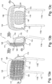
Fig. 8 bis 12 dargestellte Kopfstütze 110 entspricht der in denFig. 5 bis 7 dargestellten Kopfstütze 110, wobei gemäß dem einzigen Unterschied die Kopfanlagefläche 117 mit einem Kissen 127 versehen ist. Die Kopfanlagefläche 117 ist daher nur mittelbare Kopfanlage, da der Kopf des Sitzinsassen an dem Kissen 127 anliegt. Das Kissen 127 hat den Vorteil, dass auf die Kopfanlagefläche 117 einwirkende Kräfte von dem Kissen 127 verteilt werden. Darüber hinaus macht das Kissen die Kopfanlage komfortabler. Außerdem ist das Kissen 127 unter hygienischen Gesichtspunkten vorteilhaft, weil es lösbar an der Kopfanlagevorrichtung befestigbar ist und somit gereinigt werden kann. Das Kissen 127 kann mit allen Ausführungsbeispielen von Kopfstützen 10, 110, 210 und 310 dieser Anmeldung kombiniert werden. - Die in den
Fig. 13a bis 13e dargestellte Kopfstütze 110 gemäß einem weiteren Ausführungsbeispiel entspricht der Kopfstütze 110 gemäß derFig. 5 bis 7 , wobei der Kopfanlagebereich 116 nicht mit der federnden Struktur 122 versehen ist, sondern im Wesentlichen zu dem Rahmen 126 des Kopfanlagebereichs 116 unverformbar, also starr ausgebildet ist. Der Rahmen des Kopfanlagebereichs 116 ist aber wie oben beschrieben aufgrund der Verformbarkeit der Kopfanlagevorrichtung 111 zu dem Lagerbereich 115 bewegbar. Der Kopfanlagebereich 116 umfasst Aussparungen 128, so dass eine Gitterstruktur gebildet ist. - In den
Fig. 19 bis 25 ist eine weitere Variante der in denFig. 5 bis 7 dargestellten Kopfstütze 110 beschrieben. In Bezug auf diese Variante wird verwiesen auf die Anmeldung mit dem AktenzeichenDE 10 2017 129 830.4 . Der Kopfanlagebereich 116 umfasst bei diesem Ausführungsbeispiel ein gesondertes, im Wesentlichen starres Federteil 129, welches die Kopfanlagefläche 117 bildet. In denFig. 23 bis 25 ist erkennbar, dass das Federteil 129 mittels einer Membran 130 an einer Laibung 138 einer in dem Kopfanlagebereich 116 ausgebildeten Aussparung 131 befestigt ist, die von dem Rahmen 126 gebildet ist. Die Membran kann von jedem elastisch verformbaren Material gebildet sein. Sie ist z.B. von einem kautschukartigen Material gebildet. Alternativ zu der umlaufenden Membran 130 kann das Federteil 129 auch mittels einzelner über den Umfang verteilter Federn mit dem Kopfanlagebereich 116 verbunden sein. - Unter Wirkung einer Kraft F auf die Kopfanlagefläche 117 wird das Federteil 129 zunächst unter elastischer Verformung der Membran 130 soweit in Richtung x2 bewegt, bis eine Randfläche 132 des Federteils 129 an einer Anschlagfläche 133 der Kopfanlagevorrichtung 111 anschlägt (siehe
Fig. 25 ). Bei Einwirkung einer großen Kraft F könnte sich der ganze Kopfanlagebereich 116 mit dem Rahmen nach dem oben beschriebenen Anschlag soweit verlagern, bis eine Rückfläche 134 des Federteils 129 an der Prallfläche 120 anschlägt. Aufgrund der elastischen Rückstellkraft nehmen der Kopfanlagebereich 116 sowie das Federteil 129 nach Entlastung wieder die Ausgangsposition gemäßFig. 24 ein. - In den
Fig. 14 bis 17 ist ein anderes Ausführungsbeispiel einer Kopfstütze 210 dargestellt. Diese Kopfstütze 210 ist nicht Teil der vorliegenden Erfindung. Die Kopfstütze 210 umfasst eine Kopfanlagevorrichtung 211 in Form eines gesonderten Teiles, die mit einer Lagervorrichtung 212 an einem Fahrzeugsitz höhenverstellbar oder fest gelagert werden kann. Die Lagervorrichtung 212 umfasst Tragstangen 213a, 213b, welche fest mit der Kopfanlagevorrichtung 211 verbunden sind. Die Tragstangen 213a und 213b sind fest oder höhenverstellbar an einem Fahrzeugsitz gelagert. Alternativ zu den Tragstangen 213a und 213b könnte auch ein Tragstangenbügel verwendet werden. Gemäß einer weiteren Alternative könnte die Lagervorrichtung 212 einen Bereich aufweisen, der einteilig - z.B. aus Kunststoffspritzguss - mit der Kopfanlagevorrichtung 211 herstellbar ist und der an dem Fahrzeugsitz gelagert werden kann. - Die Kopfanlagevorrichtung 211 ist entsprechend der in
Fig. 15 dargestellten Seitenansicht etwa O-förmig geformt und insgesamt etwa rohr- oder hülsenförmig ausgebildet. Die Kopfanlagevorrichtung 211 weist einen Kopfanlagebereich 214 mit einer Kopfanlagefläche 215 sowie einen Lagerbereich 216 auf. Der Kopfanlagebereich 214 ist schaumlos hergestellt und von einem Vollmaterial gebildet. Der Lagerbereich 216 umfasst Aussparungen 217, die von den Tragstangen 213a und 213b durchgriffen werden sowie Aufnahmesitze 218, in welchen obere Endbereiche 219 der Tragstangen 213a und 213b aufgenommen und befestigt sind. - Die Kopfanlagevorrichtung 211 weist seitlich Aussparungen 220a und 220b sowie eine rückwärtige Aussparung 221 in dem Lagerbereich 216 auf. Der Kopfanlagebereich 214 ist mit Aussparungen 222 versehen, so dass ein Gitter gebildet ist. Das Material der Kopfanlagevorrichtung 211 ist im Wesentlichen unverformbar.
- Die in den
Fig. 18 und 18a dargestellte Kopfstütze 210 ist nicht Teil der vorliegenden Erfindung. Sie entspricht der Kopfstütze 210 derFig. 14 bis 17 , wobei die Kopfanlagefläche 215 mit einer Weichkomponente 223 versehen ist, die eine komfortable Anlage des Sitzinsassen gewährleistet. Die Weichkomponente 223 kann z.B. von einem Silikon gebildet sein. Die Weichkomponente 223 kann z.B. zusammen mit der Kopfanlagevorrichtung 211 - z.B. im 2-K-Spritzgießverfahren - hergestellt werden. Wie z.B. inFig. 23 erkennbar, umgreift die Weichkomponente 223 die von den Aussparungen 222 gebildeten Stege des Kopfanlagebereichs 214 bis in eine Laibung der Aussparung 222.
Claims (10)
- Kopfstütze für einen Sitz, insbesondere einen Fahrzeugsitz, mit einer Kopfanlagevorrichtung (111) mit einem Kopfanlagebereich (116), der eine Kopfanlagefläche (117) ausbildet sowie mit einer Lagervorrichtung (112), wobei die Kopfanlagevorrichtung (111) an der Lagervorrichtung (112) gelagert ist und wobei die Lagervorrichtung (112) an einem Fahrzeugsitz lagerbar ist,wobei die Kopfanlagevorrichtung (111) einteilig, insbesondere als Kunststoffspritzgießteil, ausgebildet ist, undwobei die Kopfanlagevorrichtung (111) als geformte Platte ausgebildet ist, dadurch gekennzeichnet, dass der Kopfanlagebereich (116) ein freies Ende und freie Seitenbereiche (137a, 137b) aufweist und ein unterer Endbereich des Kopfanlagebereichs (116) mit der Lagervorrichtung (112) verbunden ist, wobei ein Lagerbereich (115) der Kopfanlagevorrichtung (111) klammerartig geformt ist und einen horizontal verlaufenden unteren Bereich (118), einen weiteren horizontal verlaufenden Abschnitt (119) sowie einen vertikal verlaufenden Bereich (136) aufweist.
- Kopfstütze nach Anspruch 1, dadurch gekennzeichnet, dass die Platte aus Vollmaterial gebildet ist.
- Kopfstütze nach Anspruch 1 oder 2, dadurch gekennzeichnet, dass die Platte schaumfrei ausgebildet ist.
- Kopfstütze nach einem der vorangehenden Ansprüche, dadurch gekennzeichnet, dass der Kopfanlagebereich (116) einen Rahmen (126) bildet.
- Kopfstütze nach Anspruch 4, dadurch gekennzeichnet, dass der Rahmen (126) steif ausgebildet ist und eine elastisch verformbare Struktur (122), die wenigstens teilweise die Kopfanlagefläche (117) bildet, an dem Rahmen gehalten ist.
- Kopfstütze nach Anspruch 4, dadurch gekennzeichnet, dass der Rahmen (126) steif ausgebildet ist und dass an dem Rahmen (126) eine Folie, insbesondere eine transparente Folie, oder ein Netz gehalten ist, wobei die Folie oder das Netz wenigstens teilweise die Kopfanlagefläche (117) bildet.
- Kopfstütze nach einem der vorangehenden Ansprüche, dadurch gekennzeichnet, dass die Kopfanlagevorrichtung (111) und / oder die Lagervorrichtung (112) eine Prallfläche (120) für den Kopfanlagebereich (116) bildet.
- Kopfstütze nach einem der vorangehenden Ansprüche, dadurch gekennzeichnet, dass der Kopfanlagebereich (116) mit einer elastischen Struktur (122) versehen ist.
- Kopfstütze nach einem der vorangehenden Ansprüche, dadurch gekennzeichnet, dass der Kopfanlagebereich (116) wenigstens teilweise eine Struktur bildet, die als Gitter oder als Folie ausgebildet ist.
- Kopfstütze nach einem der vorangehenden Ansprüche, dadurch gekennzeichnet, dass die Kopfanlagefläche (117) mit einer Schicht aus einem weichen Material versehen ist.
Applications Claiming Priority (5)
| Application Number | Priority Date | Filing Date | Title |
|---|---|---|---|
| DE102017001218 | 2017-02-09 | ||
| DE102017129857.6A DE102017129857A1 (de) | 2017-02-09 | 2017-12-13 | Kopfstütze |
| DE102017129830.4A DE102017129830B4 (de) | 2017-02-09 | 2017-12-13 | Kopfstütze |
| DE102017129831.2A DE102017129831A1 (de) | 2017-02-09 | 2017-12-13 | Kopfstütze |
| PCT/DE2018/000022 WO2018145684A1 (de) | 2017-02-09 | 2018-02-07 | Köpfstütze |
Publications (2)
| Publication Number | Publication Date |
|---|---|
| EP3580092A1 EP3580092A1 (de) | 2019-12-18 |
| EP3580092B1 true EP3580092B1 (de) | 2024-09-18 |
Family
ID=62909817
Family Applications (3)
| Application Number | Title | Priority Date | Filing Date |
|---|---|---|---|
| EP18710298.3A Active EP3580091B1 (de) | 2017-02-09 | 2018-02-07 | Kopfstütze |
| EP18710299.1A Active EP3580093B1 (de) | 2017-02-09 | 2018-02-07 | Kopfstütze |
| EP18709246.5A Active EP3580092B1 (de) | 2017-02-09 | 2018-02-07 | Köpfstütze |
Family Applications Before (2)
| Application Number | Title | Priority Date | Filing Date |
|---|---|---|---|
| EP18710298.3A Active EP3580091B1 (de) | 2017-02-09 | 2018-02-07 | Kopfstütze |
| EP18710299.1A Active EP3580093B1 (de) | 2017-02-09 | 2018-02-07 | Kopfstütze |
Country Status (6)
| Country | Link |
|---|---|
| US (1) | US11529899B2 (de) |
| EP (3) | EP3580091B1 (de) |
| JP (1) | JP6792719B2 (de) |
| CN (3) | CN109952226B (de) |
| DE (3) | DE102017129857A1 (de) |
| WO (3) | WO2018145686A1 (de) |
Families Citing this family (5)
| Publication number | Priority date | Publication date | Assignee | Title |
|---|---|---|---|---|
| DE102017129857A1 (de) | 2017-02-09 | 2018-08-09 | Grammer Ag | Kopfstütze |
| FR3087718B1 (fr) * | 2018-10-24 | 2020-10-16 | Faurecia Interieur Ind | Accoudoir de vehicule |
| DE102019206828A1 (de) * | 2019-05-10 | 2020-11-12 | Volkswagen Aktiengesellschaft | Kopfstütze und Fahrzeugsitz |
| US11279274B1 (en) * | 2020-12-16 | 2022-03-22 | Ford Global Technologies, Llc | Additively manufactured trim article |
| DE202022100794U1 (de) | 2022-02-11 | 2023-06-07 | Armin Sander | Stützstruktur, insbesondere als Lordosenstütze |
Family Cites Families (38)
| Publication number | Priority date | Publication date | Assignee | Title |
|---|---|---|---|---|
| US2931427A (en) | 1959-02-24 | 1960-04-05 | Goldstein Joseph | Ventilated seat cushion |
| DE3226149C2 (de) | 1982-07-13 | 1987-03-26 | Keiper Recaro GmbH & Co, 7312 Kirchheim | Polsterträger für eine Kopfstütze |
| US4863218A (en) * | 1988-08-18 | 1989-09-05 | Pelton & Crane | Articulated headrest mechanism |
| NL9400588A (nl) * | 1994-04-13 | 1995-11-01 | Johannes Theodorus Marie Rasen | Stoel. |
| GB2315408B (en) * | 1996-07-23 | 1999-12-01 | Autoliv Dev | Improvements in or relating to a head-rest |
| CN2565322Y (zh) * | 2002-07-30 | 2003-08-13 | 钟秋媛 | 木椅之头枕的角度调整装置 |
| US7100990B2 (en) * | 2003-10-22 | 2006-09-05 | Tachi-S Co. Ltd. | Seat back structure of vehicle seat |
| US20050127735A1 (en) | 2003-11-03 | 2005-06-16 | Kenneth Munsch | Vehicle seat with adjustable support system |
| DE10355773B3 (de) * | 2003-11-26 | 2005-01-20 | Grammer Ag | Kopfstütze für Kraftfahrzeugsitze |
| US7070205B2 (en) * | 2003-11-28 | 2006-07-04 | C. Rob. Hammerstein Gmbh & Co. Kg | Headrest of a vehicle seat with a supporting member |
| WO2006006930A1 (en) * | 2004-07-09 | 2006-01-19 | Kongsberg Automotive Ab | Insert for a head restraint in a vehicle seat and a head restraint with such an insert |
| EP1952723A4 (de) * | 2005-11-14 | 2013-04-03 | Okamura Corp | Kopfstützvorrichtung eines stuhls |
| CN2870641Y (zh) * | 2006-01-23 | 2007-02-21 | 潜龙科技实业有限公司 | 汽车的护枕 |
| US7740321B2 (en) * | 2006-05-12 | 2010-06-22 | Herman Miller, Inc. | Suspended pixelated seating structure |
| US20080122284A1 (en) * | 2006-08-10 | 2008-05-29 | Jui Hung Yang | Supporting structure for a chair |
| CN201178854Y (zh) * | 2008-03-26 | 2009-01-14 | 科景实业有限公司 | 具弹性缓冲效果的办公椅头枕组 |
| CN201516817U (zh) * | 2009-10-21 | 2010-06-30 | 吴亚军 | 一种汽车护枕 |
| US20110133531A1 (en) * | 2009-12-09 | 2011-06-09 | Yeh Chia-Chang | Seat applicable to vehicles |
| CN102248904A (zh) * | 2010-05-18 | 2011-11-23 | 武建民 | 汽车气囊式腰托及头枕外套 |
| US8864000B2 (en) * | 2010-08-26 | 2014-10-21 | Paul W. Meyer | Portable visual display panel mounting device, system and method |
| CN103260945B (zh) * | 2010-12-24 | 2016-01-20 | 提爱思科技股份有限公司 | 头枕的前后位置调整装置 |
| CN102963277B (zh) * | 2011-08-30 | 2015-11-25 | 明门香港股份有限公司 | 儿童座椅及其制造方法 |
| JP2013184488A (ja) * | 2012-03-06 | 2013-09-19 | Toyota Boshoku Corp | ヘッドレスト |
| JP6005512B2 (ja) | 2012-12-28 | 2016-10-12 | 株式会社タチエス | ヘッドレスト |
| US20140217788A1 (en) | 2013-02-05 | 2014-08-07 | Michael Norwood | Vehicle seat apparatus for collision injury prevention |
| DE102013103382A1 (de) | 2013-04-04 | 2014-10-09 | Recaro Aircraft Seating Gmbh & Co. Kg | Armlehnenvorrichtung |
| US9254764B2 (en) * | 2013-07-01 | 2016-02-09 | Ford Global Technologies, Llc | Seat with integrated trim assembly and head restraint |
| CN203555439U (zh) * | 2013-07-05 | 2014-04-23 | 张德敏 | 新型透气靠背垫 |
| JP6198317B2 (ja) * | 2013-10-25 | 2017-09-20 | 株式会社岡村製作所 | 椅子用基板構造及び椅子 |
| CN203662313U (zh) * | 2014-01-22 | 2014-06-25 | 安吉富和家具有限公司 | 具有弹性支承头枕的座椅 |
| US9833025B2 (en) * | 2014-06-06 | 2017-12-05 | Travis Lyn KNAPP | Adjustable head and neck support system |
| EP3281822B1 (de) | 2014-06-16 | 2019-07-24 | Safran Seats USA LLC | Leichte kopfstützen mit aufhängungsnetz und tragrahmen |
| CN204245650U (zh) * | 2014-10-17 | 2015-04-08 | 安吉恒林科技发展有限公司 | 椅子头枕 |
| DE102015000108A1 (de) * | 2015-01-14 | 2016-07-14 | Grammer Ag | Lagervorrichtung und Kopfstütze |
| DE102015212510A1 (de) | 2015-07-03 | 2017-01-05 | Johnson Controls Gmbh | Kopfstützenkörper und Kopfstütze |
| CN205098002U (zh) * | 2015-10-26 | 2016-03-23 | 成都云科新能汽车技术有限公司 | 一种汽车座椅头枕主动防护装置 |
| KR101656661B1 (ko) * | 2016-02-05 | 2016-09-23 | 주식회사 체어로 | 목지지부로 가변되는 의자용 헤드 레스트 |
| DE102017129857A1 (de) | 2017-02-09 | 2018-08-09 | Grammer Ag | Kopfstütze |
-
2017
- 2017-12-13 DE DE102017129857.6A patent/DE102017129857A1/de active Pending
- 2017-12-13 DE DE102017129830.4A patent/DE102017129830B4/de active Active
- 2017-12-13 DE DE102017129831.2A patent/DE102017129831A1/de active Pending
-
2018
- 2018-02-07 US US16/331,973 patent/US11529899B2/en active Active
- 2018-02-07 EP EP18710298.3A patent/EP3580091B1/de active Active
- 2018-02-07 JP JP2019540632A patent/JP6792719B2/ja active Active
- 2018-02-07 CN CN201880004370.9A patent/CN109952226B/zh active Active
- 2018-02-07 EP EP18710299.1A patent/EP3580093B1/de active Active
- 2018-02-07 CN CN201880020787.4A patent/CN110461648B/zh active Active
- 2018-02-07 WO PCT/DE2018/000024 patent/WO2018145686A1/de not_active Ceased
- 2018-02-07 WO PCT/DE2018/000022 patent/WO2018145684A1/de not_active Ceased
- 2018-02-07 EP EP18709246.5A patent/EP3580092B1/de active Active
- 2018-02-07 CN CN201880021318.4A patent/CN110461649B/zh active Active
- 2018-02-07 WO PCT/DE2018/000023 patent/WO2018145685A1/de not_active Ceased
Also Published As
| Publication number | Publication date |
|---|---|
| EP3580093A1 (de) | 2019-12-18 |
| WO2018145684A1 (de) | 2018-08-16 |
| DE102017129831A1 (de) | 2018-08-09 |
| EP3580092A1 (de) | 2019-12-18 |
| WO2018145686A1 (de) | 2018-08-16 |
| WO2018145685A1 (de) | 2018-08-16 |
| CN110461648A (zh) | 2019-11-15 |
| CN109952226B (zh) | 2021-12-31 |
| DE102017129857A1 (de) | 2018-08-09 |
| CN109952226A (zh) | 2019-06-28 |
| EP3580091B1 (de) | 2023-04-05 |
| JP6792719B2 (ja) | 2020-11-25 |
| JP2020505271A (ja) | 2020-02-20 |
| EP3580091A1 (de) | 2019-12-18 |
| EP3580093B1 (de) | 2024-07-03 |
| CN110461649B (zh) | 2022-06-03 |
| CN110461648B (zh) | 2022-05-27 |
| DE102017129830B4 (de) | 2024-08-29 |
| CN110461649A (zh) | 2019-11-15 |
| US11529899B2 (en) | 2022-12-20 |
| US20210291712A1 (en) | 2021-09-23 |
| DE102017129830A1 (de) | 2018-08-09 |
Similar Documents
| Publication | Publication Date | Title |
|---|---|---|
| EP3580092B1 (de) | Köpfstütze | |
| EP1095815B1 (de) | Fahrzeugsitz für ein Kraftfahrzeug mit einer Rückenlehne | |
| DE102008060993A1 (de) | Geschichtetes Sitzpolster mit gerichteter Durchbiegung für Kindersitz und Insassensicherheit | |
| EP3250400B1 (de) | Leichtbausitz für fahrzeuge | |
| DE102015201279B4 (de) | Verstellbare kopfstütze | |
| EP1501389B1 (de) | Sitzeinlage und verfahren zu ihrer herstellung | |
| DE102013209465A1 (de) | Schaumteil, insbesondere für einen Fahrzeugsitz, sowie Werkzeug und Verfahren zur Herstellung eines Schaumteils | |
| DE102014117941A1 (de) | Armlehne mit Strukturstoffsubstrat für ein Fahrzeug | |
| WO2008014850A2 (de) | Aktuierungsmittel, insbesondere für kopfstütze eines fahrzeugsitzes | |
| EP2161159B1 (de) | Sicherheitsvorrichtung für einen Kindersitz in einem Fahrzeug | |
| DE102016212222A1 (de) | Fahrzeugsitz | |
| DE102016221031A1 (de) | Polster | |
| DE102011119059B4 (de) | Sitzkissen | |
| EP2877368B1 (de) | Stützvorrichtung für einen sitz und damit ausgerüsteter fahrzeugsitz | |
| DE102019110755A1 (de) | Verschiebbar lösbare mittelkonsole | |
| DE102008011246A1 (de) | Fahrzeugsitz, insbesondere Kraftfahrzeugsitz | |
| DE102023106754A1 (de) | Trägerelement für einen fahrzeugsitz, fahrzeugsitz und zugehöriges montageverfahren | |
| DE102014225684B4 (de) | Pneumatische Verstellanordnung für einen Fahrzeugsitz, sowie Fahrzeugsitz | |
| EP1095816B1 (de) | Kopfstützenanordnung für einen Fahrzeugsitz | |
| DE1630981A1 (de) | Schutzpolster | |
| EP1302360B1 (de) | Rücksitz eines Fahrzeuges | |
| DE102014110421B4 (de) | Sitz mit automatischem Leibgurtanpassungsmechanismus | |
| DE102011011516A1 (de) | Sitzlehne für eine Sitzanlage eines Kraftwagens |
Legal Events
| Date | Code | Title | Description |
|---|---|---|---|
| STAA | Information on the status of an ep patent application or granted ep patent |
Free format text: STATUS: UNKNOWN |
|
| STAA | Information on the status of an ep patent application or granted ep patent |
Free format text: STATUS: THE INTERNATIONAL PUBLICATION HAS BEEN MADE |
|
| PUAI | Public reference made under article 153(3) epc to a published international application that has entered the european phase |
Free format text: ORIGINAL CODE: 0009012 |
|
| STAA | Information on the status of an ep patent application or granted ep patent |
Free format text: STATUS: REQUEST FOR EXAMINATION WAS MADE |
|
| 17P | Request for examination filed |
Effective date: 20190809 |
|
| AK | Designated contracting states |
Kind code of ref document: A1 Designated state(s): AL AT BE BG CH CY CZ DE DK EE ES FI FR GB GR HR HU IE IS IT LI LT LU LV MC MK MT NL NO PL PT RO RS SE SI SK SM TR |
|
| AX | Request for extension of the european patent |
Extension state: BA ME |
|
| DAV | Request for validation of the european patent (deleted) | ||
| DAX | Request for extension of the european patent (deleted) | ||
| STAA | Information on the status of an ep patent application or granted ep patent |
Free format text: STATUS: EXAMINATION IS IN PROGRESS |
|
| 17Q | First examination report despatched |
Effective date: 20201120 |
|
| RAP1 | Party data changed (applicant data changed or rights of an application transferred) |
Owner name: GRAMMER AG |
|
| REG | Reference to a national code |
Ref legal event code: R079 Free format text: PREVIOUS MAIN CLASS: B60N0002803000 Ipc: B60N0002800000 Ref country code: DE Ref legal event code: R079 Ref document number: 502018015145 Country of ref document: DE Free format text: PREVIOUS MAIN CLASS: B60N0002803000 Ipc: B60N0002800000 |
|
| GRAP | Despatch of communication of intention to grant a patent |
Free format text: ORIGINAL CODE: EPIDOSNIGR1 |
|
| STAA | Information on the status of an ep patent application or granted ep patent |
Free format text: STATUS: GRANT OF PATENT IS INTENDED |
|
| RIC1 | Information provided on ipc code assigned before grant |
Ipc: B60N 2/70 20060101ALI20240418BHEP Ipc: B60N 2/80 20180101AFI20240418BHEP |
|
| INTG | Intention to grant announced |
Effective date: 20240506 |
|
| P01 | Opt-out of the competence of the unified patent court (upc) registered |
Free format text: CASE NUMBER: APP_34716/2024 Effective date: 20240610 |
|
| GRAS | Grant fee paid |
Free format text: ORIGINAL CODE: EPIDOSNIGR3 |
|
| GRAA | (expected) grant |
Free format text: ORIGINAL CODE: 0009210 |
|
| STAA | Information on the status of an ep patent application or granted ep patent |
Free format text: STATUS: THE PATENT HAS BEEN GRANTED |
|
| AK | Designated contracting states |
Kind code of ref document: B1 Designated state(s): AL AT BE BG CH CY CZ DE DK EE ES FI FR GB GR HR HU IE IS IT LI LT LU LV MC MK MT NL NO PL PT RO RS SE SI SK SM TR |
|
| REG | Reference to a national code |
Ref country code: GB Ref legal event code: FG4D Free format text: NOT ENGLISH |
|
| REG | Reference to a national code |
Ref country code: CH Ref legal event code: EP |
|
| REG | Reference to a national code |
Ref country code: DE Ref legal event code: R096 Ref document number: 502018015145 Country of ref document: DE |
|
| REG | Reference to a national code |
Ref country code: IE Ref legal event code: FG4D Free format text: LANGUAGE OF EP DOCUMENT: GERMAN |
|
| REG | Reference to a national code |
Ref country code: LT Ref legal event code: MG9D |
|
| PG25 | Lapsed in a contracting state [announced via postgrant information from national office to epo] |
Ref country code: NO Free format text: LAPSE BECAUSE OF FAILURE TO SUBMIT A TRANSLATION OF THE DESCRIPTION OR TO PAY THE FEE WITHIN THE PRESCRIBED TIME-LIMIT Effective date: 20241218 |
|
| PG25 | Lapsed in a contracting state [announced via postgrant information from national office to epo] |
Ref country code: GR Free format text: LAPSE BECAUSE OF FAILURE TO SUBMIT A TRANSLATION OF THE DESCRIPTION OR TO PAY THE FEE WITHIN THE PRESCRIBED TIME-LIMIT Effective date: 20241219 Ref country code: FI Free format text: LAPSE BECAUSE OF FAILURE TO SUBMIT A TRANSLATION OF THE DESCRIPTION OR TO PAY THE FEE WITHIN THE PRESCRIBED TIME-LIMIT Effective date: 20240918 |
|
| PG25 | Lapsed in a contracting state [announced via postgrant information from national office to epo] |
Ref country code: BG Free format text: LAPSE BECAUSE OF FAILURE TO SUBMIT A TRANSLATION OF THE DESCRIPTION OR TO PAY THE FEE WITHIN THE PRESCRIBED TIME-LIMIT Effective date: 20240918 |
|
| PG25 | Lapsed in a contracting state [announced via postgrant information from national office to epo] |
Ref country code: LV Free format text: LAPSE BECAUSE OF FAILURE TO SUBMIT A TRANSLATION OF THE DESCRIPTION OR TO PAY THE FEE WITHIN THE PRESCRIBED TIME-LIMIT Effective date: 20240918 |
|
| PG25 | Lapsed in a contracting state [announced via postgrant information from national office to epo] |
Ref country code: HR Free format text: LAPSE BECAUSE OF FAILURE TO SUBMIT A TRANSLATION OF THE DESCRIPTION OR TO PAY THE FEE WITHIN THE PRESCRIBED TIME-LIMIT Effective date: 20240918 |
|
| REG | Reference to a national code |
Ref country code: NL Ref legal event code: MP Effective date: 20240918 |
|
| PG25 | Lapsed in a contracting state [announced via postgrant information from national office to epo] |
Ref country code: RS Free format text: LAPSE BECAUSE OF FAILURE TO SUBMIT A TRANSLATION OF THE DESCRIPTION OR TO PAY THE FEE WITHIN THE PRESCRIBED TIME-LIMIT Effective date: 20241218 |
|
| PG25 | Lapsed in a contracting state [announced via postgrant information from national office to epo] |
Ref country code: RS Free format text: LAPSE BECAUSE OF FAILURE TO SUBMIT A TRANSLATION OF THE DESCRIPTION OR TO PAY THE FEE WITHIN THE PRESCRIBED TIME-LIMIT Effective date: 20241218 Ref country code: NO Free format text: LAPSE BECAUSE OF FAILURE TO SUBMIT A TRANSLATION OF THE DESCRIPTION OR TO PAY THE FEE WITHIN THE PRESCRIBED TIME-LIMIT Effective date: 20241218 Ref country code: LV Free format text: LAPSE BECAUSE OF FAILURE TO SUBMIT A TRANSLATION OF THE DESCRIPTION OR TO PAY THE FEE WITHIN THE PRESCRIBED TIME-LIMIT Effective date: 20240918 Ref country code: HR Free format text: LAPSE BECAUSE OF FAILURE TO SUBMIT A TRANSLATION OF THE DESCRIPTION OR TO PAY THE FEE WITHIN THE PRESCRIBED TIME-LIMIT Effective date: 20240918 Ref country code: GR Free format text: LAPSE BECAUSE OF FAILURE TO SUBMIT A TRANSLATION OF THE DESCRIPTION OR TO PAY THE FEE WITHIN THE PRESCRIBED TIME-LIMIT Effective date: 20241219 Ref country code: FI Free format text: LAPSE BECAUSE OF FAILURE TO SUBMIT A TRANSLATION OF THE DESCRIPTION OR TO PAY THE FEE WITHIN THE PRESCRIBED TIME-LIMIT Effective date: 20240918 Ref country code: BG Free format text: LAPSE BECAUSE OF FAILURE TO SUBMIT A TRANSLATION OF THE DESCRIPTION OR TO PAY THE FEE WITHIN THE PRESCRIBED TIME-LIMIT Effective date: 20240918 |
|
| PG25 | Lapsed in a contracting state [announced via postgrant information from national office to epo] |
Ref country code: NL Free format text: LAPSE BECAUSE OF FAILURE TO SUBMIT A TRANSLATION OF THE DESCRIPTION OR TO PAY THE FEE WITHIN THE PRESCRIBED TIME-LIMIT Effective date: 20240918 |
|
| PG25 | Lapsed in a contracting state [announced via postgrant information from national office to epo] |
Ref country code: IS Free format text: LAPSE BECAUSE OF FAILURE TO SUBMIT A TRANSLATION OF THE DESCRIPTION OR TO PAY THE FEE WITHIN THE PRESCRIBED TIME-LIMIT Effective date: 20250118 Ref country code: PT Free format text: LAPSE BECAUSE OF FAILURE TO SUBMIT A TRANSLATION OF THE DESCRIPTION OR TO PAY THE FEE WITHIN THE PRESCRIBED TIME-LIMIT Effective date: 20250120 |
|
| PGFP | Annual fee paid to national office [announced via postgrant information from national office to epo] |
Ref country code: DE Payment date: 20250218 Year of fee payment: 8 |
|
| PG25 | Lapsed in a contracting state [announced via postgrant information from national office to epo] |
Ref country code: RO Free format text: LAPSE BECAUSE OF FAILURE TO SUBMIT A TRANSLATION OF THE DESCRIPTION OR TO PAY THE FEE WITHIN THE PRESCRIBED TIME-LIMIT Effective date: 20240918 Ref country code: SM Free format text: LAPSE BECAUSE OF FAILURE TO SUBMIT A TRANSLATION OF THE DESCRIPTION OR TO PAY THE FEE WITHIN THE PRESCRIBED TIME-LIMIT Effective date: 20240918 |
|
| PG25 | Lapsed in a contracting state [announced via postgrant information from national office to epo] |
Ref country code: ES Free format text: LAPSE BECAUSE OF FAILURE TO SUBMIT A TRANSLATION OF THE DESCRIPTION OR TO PAY THE FEE WITHIN THE PRESCRIBED TIME-LIMIT Effective date: 20240918 |
|
| PG25 | Lapsed in a contracting state [announced via postgrant information from national office to epo] |
Ref country code: EE Free format text: LAPSE BECAUSE OF FAILURE TO SUBMIT A TRANSLATION OF THE DESCRIPTION OR TO PAY THE FEE WITHIN THE PRESCRIBED TIME-LIMIT Effective date: 20240918 |
|
| PG25 | Lapsed in a contracting state [announced via postgrant information from national office to epo] |
Ref country code: PL Free format text: LAPSE BECAUSE OF FAILURE TO SUBMIT A TRANSLATION OF THE DESCRIPTION OR TO PAY THE FEE WITHIN THE PRESCRIBED TIME-LIMIT Effective date: 20240918 Ref country code: CZ Free format text: LAPSE BECAUSE OF FAILURE TO SUBMIT A TRANSLATION OF THE DESCRIPTION OR TO PAY THE FEE WITHIN THE PRESCRIBED TIME-LIMIT Effective date: 20240918 |
|
| PGFP | Annual fee paid to national office [announced via postgrant information from national office to epo] |
Ref country code: FR Payment date: 20250219 Year of fee payment: 8 |
|
| PG25 | Lapsed in a contracting state [announced via postgrant information from national office to epo] |
Ref country code: SK Free format text: LAPSE BECAUSE OF FAILURE TO SUBMIT A TRANSLATION OF THE DESCRIPTION OR TO PAY THE FEE WITHIN THE PRESCRIBED TIME-LIMIT Effective date: 20240918 |
|
| PGFP | Annual fee paid to national office [announced via postgrant information from national office to epo] |
Ref country code: IT Payment date: 20250228 Year of fee payment: 8 |
|
| REG | Reference to a national code |
Ref country code: DE Ref legal event code: R097 Ref document number: 502018015145 Country of ref document: DE |
|
| PG25 | Lapsed in a contracting state [announced via postgrant information from national office to epo] |
Ref country code: DK Free format text: LAPSE BECAUSE OF FAILURE TO SUBMIT A TRANSLATION OF THE DESCRIPTION OR TO PAY THE FEE WITHIN THE PRESCRIBED TIME-LIMIT Effective date: 20240918 |
|
| PLBE | No opposition filed within time limit |
Free format text: ORIGINAL CODE: 0009261 |
|
| STAA | Information on the status of an ep patent application or granted ep patent |
Free format text: STATUS: NO OPPOSITION FILED WITHIN TIME LIMIT |
|
| 26N | No opposition filed |
Effective date: 20250619 |
|
| PG25 | Lapsed in a contracting state [announced via postgrant information from national office to epo] |
Ref country code: SE Free format text: LAPSE BECAUSE OF FAILURE TO SUBMIT A TRANSLATION OF THE DESCRIPTION OR TO PAY THE FEE WITHIN THE PRESCRIBED TIME-LIMIT Effective date: 20240918 |
|
| PG25 | Lapsed in a contracting state [announced via postgrant information from national office to epo] |
Ref country code: MC Free format text: LAPSE BECAUSE OF FAILURE TO SUBMIT A TRANSLATION OF THE DESCRIPTION OR TO PAY THE FEE WITHIN THE PRESCRIBED TIME-LIMIT Effective date: 20240918 |
|
| REG | Reference to a national code |
Ref country code: CH Ref legal event code: PL |
|
| PG25 | Lapsed in a contracting state [announced via postgrant information from national office to epo] |
Ref country code: LU Free format text: LAPSE BECAUSE OF NON-PAYMENT OF DUE FEES Effective date: 20250207 |
|
| PG25 | Lapsed in a contracting state [announced via postgrant information from national office to epo] |
Ref country code: CH Free format text: LAPSE BECAUSE OF NON-PAYMENT OF DUE FEES Effective date: 20250228 |
|
| GBPC | Gb: european patent ceased through non-payment of renewal fee |
Effective date: 20250207 |
|
| REG | Reference to a national code |
Ref country code: BE Ref legal event code: MM Effective date: 20250228 |
|
| PG25 | Lapsed in a contracting state [announced via postgrant information from national office to epo] |
Ref country code: GB Free format text: LAPSE BECAUSE OF NON-PAYMENT OF DUE FEES Effective date: 20250207 |
|
| PG25 | Lapsed in a contracting state [announced via postgrant information from national office to epo] |
Ref country code: BE Free format text: LAPSE BECAUSE OF NON-PAYMENT OF DUE FEES Effective date: 20250228 |
|
| PG25 | Lapsed in a contracting state [announced via postgrant information from national office to epo] |
Ref country code: IE Free format text: LAPSE BECAUSE OF NON-PAYMENT OF DUE FEES Effective date: 20250207 |