EP3578880B1 - Betriebsgerät mit wärmeleitstruktur - Google Patents
Betriebsgerät mit wärmeleitstruktur Download PDFInfo
- Publication number
- EP3578880B1 EP3578880B1 EP19176075.0A EP19176075A EP3578880B1 EP 3578880 B1 EP3578880 B1 EP 3578880B1 EP 19176075 A EP19176075 A EP 19176075A EP 3578880 B1 EP3578880 B1 EP 3578880B1
- Authority
- EP
- European Patent Office
- Prior art keywords
- heat
- coil
- conducting structure
- operating device
- core
- Prior art date
- Legal status (The legal status is an assumption and is not a legal conclusion. Google has not performed a legal analysis and makes no representation as to the accuracy of the status listed.)
- Active
Links
Images

Classifications
-
- F—MECHANICAL ENGINEERING; LIGHTING; HEATING; WEAPONS; BLASTING
- F21—LIGHTING
- F21V—FUNCTIONAL FEATURES OR DETAILS OF LIGHTING DEVICES OR SYSTEMS THEREOF; STRUCTURAL COMBINATIONS OF LIGHTING DEVICES WITH OTHER ARTICLES, NOT OTHERWISE PROVIDED FOR
- F21V23/00—Arrangement of electric circuit elements in or on lighting devices
- F21V23/003—Arrangement of electric circuit elements in or on lighting devices the elements being electronics drivers or controllers for operating the light source, e.g. for a LED array
- F21V23/007—Arrangement of electric circuit elements in or on lighting devices the elements being electronics drivers or controllers for operating the light source, e.g. for a LED array enclosed in a casing
-
- F—MECHANICAL ENGINEERING; LIGHTING; HEATING; WEAPONS; BLASTING
- F21—LIGHTING
- F21V—FUNCTIONAL FEATURES OR DETAILS OF LIGHTING DEVICES OR SYSTEMS THEREOF; STRUCTURAL COMBINATIONS OF LIGHTING DEVICES WITH OTHER ARTICLES, NOT OTHERWISE PROVIDED FOR
- F21V23/00—Arrangement of electric circuit elements in or on lighting devices
- F21V23/02—Arrangement of electric circuit elements in or on lighting devices the elements being transformers, impedances or power supply units, e.g. a transformer with a rectifier
-
- F—MECHANICAL ENGINEERING; LIGHTING; HEATING; WEAPONS; BLASTING
- F21—LIGHTING
- F21V—FUNCTIONAL FEATURES OR DETAILS OF LIGHTING DEVICES OR SYSTEMS THEREOF; STRUCTURAL COMBINATIONS OF LIGHTING DEVICES WITH OTHER ARTICLES, NOT OTHERWISE PROVIDED FOR
- F21V23/00—Arrangement of electric circuit elements in or on lighting devices
- F21V23/02—Arrangement of electric circuit elements in or on lighting devices the elements being transformers, impedances or power supply units, e.g. a transformer with a rectifier
- F21V23/026—Fastening of transformers or ballasts
-
- H—ELECTRICITY
- H01—ELECTRIC ELEMENTS
- H01F—MAGNETS; INDUCTANCES; TRANSFORMERS; SELECTION OF MATERIALS FOR THEIR MAGNETIC PROPERTIES
- H01F27/00—Details of transformers or inductances, in general
- H01F27/02—Casings
- H01F27/025—Constructional details relating to cooling
-
- H—ELECTRICITY
- H01—ELECTRIC ELEMENTS
- H01F—MAGNETS; INDUCTANCES; TRANSFORMERS; SELECTION OF MATERIALS FOR THEIR MAGNETIC PROPERTIES
- H01F27/00—Details of transformers or inductances, in general
- H01F27/08—Cooling; Ventilating
- H01F27/22—Cooling by heat conduction through solid or powdered fillings
-
- H—ELECTRICITY
- H05—ELECTRIC TECHNIQUES NOT OTHERWISE PROVIDED FOR
- H05B—ELECTRIC HEATING; ELECTRIC LIGHT SOURCES NOT OTHERWISE PROVIDED FOR; CIRCUIT ARRANGEMENTS FOR ELECTRIC LIGHT SOURCES, IN GENERAL
- H05B45/00—Circuit arrangements for operating light-emitting diodes [LED]
- H05B45/30—Driver circuits
-
- H—ELECTRICITY
- H01—ELECTRIC ELEMENTS
- H01F—MAGNETS; INDUCTANCES; TRANSFORMERS; SELECTION OF MATERIALS FOR THEIR MAGNETIC PROPERTIES
- H01F27/00—Details of transformers or inductances, in general
- H01F27/06—Mounting, supporting or suspending transformers, reactors or choke coils not being of the signal type
- H01F2027/065—Mounting on printed circuit boards
-
- H—ELECTRICITY
- H05—ELECTRIC TECHNIQUES NOT OTHERWISE PROVIDED FOR
- H05B—ELECTRIC HEATING; ELECTRIC LIGHT SOURCES NOT OTHERWISE PROVIDED FOR; CIRCUIT ARRANGEMENTS FOR ELECTRIC LIGHT SOURCES, IN GENERAL
- H05B45/00—Circuit arrangements for operating light-emitting diodes [LED]
- H05B45/30—Driver circuits
- H05B45/32—Pulse-control circuits
- H05B45/325—Pulse-width modulation [PWM]
Definitions
- the invention relates to an operating device for a luminaire, in particular for an LED luminaire.
- Operating devices of the type mentioned above are used to operate lamps, in particular LEDs, for example to supply the lamp with a certain voltage and/or a certain current.
- Other examples of applications are pulse width modulation, adjusting the brightness (in particular dimming) and/or the general control of the lamps.
- Coils are used for this, for example in a transformer, to provide and/or store energy so that the lamp is operated accordingly.
- Other applications of coils in such an operating device are, for example, coils for power correction (PFC), coils in an LLC converter, coils for mains input throttling, coils in flyback converters or coils generally for (intermediate) energy storage.
- coils or coil combinations such as transformers, or magnetic components generally do not work without losses and thus give off heat or waste heat in an undesirable way.
- the windings and the coil core of the coil in particular give off a lot of heat.
- This heat must be dissipated as well as possible so that it does not affect other electrical and/or electronic components, since the undesirably high temperatures can shorten the service life of the respective electrical and/or electronic component and thus the operating device.
- Capacitive components in particular are sensitive to such high temperatures.
- TIM thermal interface materials
- the EP 1 528 577 A1 discloses an operating device which has a plastic housing, wherein the plastic housing is designed in such a way that this housing always rests against the iron package of the respective coil component used (transformer or series choke) despite all manufacturing dimensional tolerances in order to enable good heat dissipation.
- the DE 10 2008 048977 A1 discloses an electronic compact assembly for mounting on a printed circuit board, comprising a housing in which a transformer is arranged and encapsulated.
- the CN 104 240 926 A discloses a transformer structure comprising a shell having a space, an induction unit, and a thermally conductive adhesive, the adhesive filling the space to cover the induction unit.
- the DE 198 14 897 A1 discloses an inductive component for high powers, comprising a toroidal band core, wherein the core provided with a winding is located in a metal housing, and the gaps within the metal housing are filled with a casting compound, wherein the self-contained core is cooled by at least one rod-shaped heat pipe.
- the EP 3 319 096 A1 discloses a magnetic core having at least one coil and a cooling structure comprising a non-metallic, heat-conducting element constructed as a heat pipe and arranged inside a hole or cavity of the core.
- the US 2002/135983 A1 discloses an energy conversion device comprising a thermally conductive base and a thermally conductive cover that can be joined to the base to form a sealed space.
- the DE 203 17 641 U1 reveals thermal bridge for toroidal inductors.
- the WO 2017/154696 A1 discloses a circuit arrangement with a printed circuit board, a heat sink which is placed on the printed circuit board, and an inductor.
- the WO 2017/154954 A1 discloses a circuit structure comprising a coil device and a heat sink to which the coil device is secured.
- the JP S61 105814 A discloses an electromagnetic device wherein three peripheral surfaces of a coil are covered with radiating surfaces so that heat from the coil is directed into the surfaces.
- the US 4,082,141 A discloses a ballast with a thermal path.
- the JP H05 67043 U3 discloses a structure for holding, for example, a transformer.
- the DE 87 16 135 U1 discloses a transformer with a magnetic core, wherein base fastening elements are provided on which vertically upstanding tabs are formed, wherein partial areas of the edges of the tabs are also welded.
- the invention is based on the object of eliminating the above-mentioned disadvantages of the prior art, i.e. in particular to conduct the heat from coils more efficiently or generally to optimize the heat development of such operating devices.
- An operating device for a luminaire, in particular for an LED luminaire, has: a coil with a coil core, and a heat conducting structure which is in surface contact with the coil core in order to conduct the heat emitted by the coil core during operation of the coil away from the coil core.
- the coil core when the coil is in operation, the coil core generates energy loss in the form of waste heat, which is efficiently transferred to the heat conduction structure by the heat conduction structure in surface contact, thereby efficiently cooling the coil core.
- the surface contact of the heat conduction structure with the coil core allows the heat to be efficiently conducted along a desired path, namely one defined by the heat conduction structure - in particular to a heat-dissipating and/or heat-distributing element of the lamp, such as a heat sink of the lamp.
- the coil core is thus cooled or the heat is conducted away from it, and on the other hand, other electrical and/or electronic components or general components of the operating device are prevented from being affected by this heat.
- the efficiency of the cooling of the coil core is consequently improved.
- the service life and reliability of the operating device is also increased, since waste heat from the coil core has less of an impact on the components of the operating device, in particular the components located near the coil. As a result, the operating device can also be used in higher ambient temperatures.
- the operating device further comprises a circuit board, wherein the coil with the heat conducting structure is provided on a first side of the circuit board in such a way that the heat conducting structure conducts the heat emitted by the coil core away from the coil core and the first side to a side of the circuit board facing away from the first side. Since sensitive electrical and/or electronic components such as capacitive components are generally provided on the coil side or on the first side (front side) of the circuit board, these components are no longer affected due to the heat being dissipated by the heat conducting structure to the second side or back of the circuit board. In this way, the components of the operating device in particular are spared from the waste heat of the coil. And since the coil is therefore also less exposed to its waste heat, its size can now be reduced.
- the coil core is arranged between walls of the heat conducting structure that are in surface contact with the coil core.
- the heat conducting structure can thus simply be placed on the coil core in order to automatically be in surface contact with the coil core.
- the heat-emitting surface is increased by the walls of the heat conducting structure that are in surface contact, so that the efficiency of heat dissipation or cooling is also improved.
- the heat conducting structure can be a wall that surrounds at least the coil core in a closed manner.
- the heat conducting structure can thus be brought into surface contact with the coil core easily, in particular automatically, when the heat conducting structure is put in place.
- the surface area of the heat conducting structure is increased, which in turn benefits the cooling.
- the closed surrounding wall also enables good thermal insulation of the components provided outside the wall.
- air can reach the coil or coil core through the opening that defines the wall, so that the convective heat transfer between the air and the coil core and thus the efficiency of the cooling is improved.
- the heat conducting structure can be a hood or cap that covers at least the coil core and preferably has a substantially U-shaped cross-section. Air can thus flow through the openings defined by the hood or the preferably U-shaped cross-section, in order to improve the convective heat transfer within the hood in particular.
- the coil core is thus covered above the coil core, so that components of the operating device in this direction in particular are protected from the waste heat of the coil core.
- the heat-dissipating surface is thus enlarged, which in turn benefits the more efficient cooling of the coil core.
- the heat conducting structure can thus simply be placed or plugged, preferably clamped, onto the coil or the coil core.
- the heat conducting structure has a mounting section for mounting the heat conducting structure in the operating device, in particular on the circuit board, and/or to the coil.
- the heat conducting structure can thus be easily connected to the operating device and/or the coil or mounted on them, for example via a material, force and/or form-fitting connection. It is preferred if the free ends of the hood or the base of the wall have or have the mounting section, so that the heat conducting structure can be mounted particularly easily.
- the heat conducting structure preferably the mounting section, has legs for dissipating heat in the direction of the second side of the circuit board.
- the legs By providing the legs, the heat-dissipating area can be increased, which in turn benefits the cooling effect of the heat conducting structure.
- the legs have an advantageous design for being connected to other heat-dissipating elements.
- the legs pass through the circuit board.
- the legs can be used to (directly) conduct heat from the front (the first side) to the back (the second side) of the circuit board. Because the legs pass through the circuit board, the legs can also be used at the same time as fastening means for fastening the heat conducting structure to the circuit board.
- the legs are preferably designed to be connected to a heat-dissipating and/or heat-distributing element of a lamp and/or the operating device.
- the legs can thus be used to conduct the waste heat from the coil core directly to these heat-dissipating and/or heat-distributing elements, i.e. in particular to conduct it away from heat-sensitive components of the operating device.
- the legs are preferably connected to a heat-dissipating and/or heat-distributing element of the operating device. This ensures that the heat emitted by the coil core and transferred to the heat-conducting structure is only conducted to this heat-dissipating and/or heat-distributing element.
- the heat-dissipating and/or heat-distributing element is preferably a heat sink or another large-area component for dissipating heat. This allows the waste heat to be dissipated in a particularly advantageous manner from the operating device, for example, to the ambient air, in order to achieve efficient cooling.
- the heat conduction structure can be made of a material that contains metal, preferably copper and/or aluminum. These materials have a particularly high thermal conductivity, so that they are particularly advantageous for efficient cooling of the coil core or for heat conduction by means of the heat conduction structure. Alternatively or additionally, the material can consist (only) of plastic (designed for high heat conduction) or contain plastic.
- the heat conduction structure can thus be designed to electrically insulate the coil in addition to cooling the coil core.
- the coil core is a ferrite core.
- Ferrite is particularly advantageous for conducting the magnetic flux of the coil.
- the heat conducting structure has cooling fins.
- the heat conducting structure thus has a surface that is optimized for heat dissipation or for heat conduction, i.e. in particular an enlarged surface.
- the cooling fins are preferably provided integrally with the heat conducting structure or the heat conducting structure is preferably shaped in such a way that it forms the cooling fins.
- the cooling fins are preferably provided on at least one side of the heat conducting structure that faces away from the coil core, so that the heat of the coil core can be easily conducted away from the coil core.
- the cooling fins are preferably provided (evenly) distributed on the surface of the heat conducting structure. It is also preferred if the cooling fins are provided on the entire surface of the heat conducting structure, wherein this surface preferably comprises the surface of the heat conducting structure that faces away from the coil core and/or the surface of the heat conducting structure that faces the coil core.
- the coil is a transformer coil, with the coil core being designed as a transformer core.
- a transformer coil, in particular its transformer core, is known to generate a lot of waste heat due to the conversion of voltage.
- the aforementioned heat conduction structure is therefore particularly advantageous for efficiently dissipating this waste heat, i.e. in particular for not affecting the transformer or other components with the waste heat.
- the transformer core has: a first section for electromagnetic interaction with a primary winding, a second section for electromagnetic interaction with a secondary winding, and a third section for connecting the first section to the second section in order to conduct the magnetic flux between the first and second sections.
- the heat conducting structure is then in surface contact with the third section. Since the third section is exposed from any winding and also has a large heat-emitting surface, the heat conducting structure can be brought into (full) surface contact with this (entire) surface, which helps to improve the efficiency of heat dissipation or cooling.
- the third section is easily accessible from outside the coil, so that the heat conducting structure can easily be brought into surface contact with the transformer core.
- the invention further relates to a luminaire, in particular an LED luminaire, comprising a lighting means, preferably an LED, and an operating device as described above for operating the lighting means.
- the figures described below show two embodiments of an operating device 1 according to the invention by way of example.
- the entire operating device is not visible, but rather only a schematic section for the sake of simplicity.
- the operating device 1 is used in a light, in particular in an LED light.
- a light (not shown in detail) can be operated using the operating device 1, in particular so that the light emits light in a desired manner.
- Examples of applications of the operating device 1 are the supply of voltage and/or current, pulse width modulation, setting the brightness (in particular dimming) and/or the general control of the light sources.
- the operating device 1 has a transformer coil 2 with a transformer core 3, wherein a heat conducting structure 4, 4' is in surface contact with the transformer core 3 in order to cool the transformer core 3 or to conduct the heat emitted by the transformer core 3 during operation of the transformer or the transformer coil 2 away from the transformer core 3.
- a heat conducting structure 4, 4' is in surface contact with the transformer core 3 in order to cool the transformer core 3 or to conduct the heat emitted by the transformer core 3 during operation of the transformer or the transformer coil 2 away from the transformer core 3.
- the heat conducting structure 4, 4' is not limited to a transformer coil 2 with a transformer core 3. Rather, the heat conducting structure 4, 4' is suitable for any coil with a coil core used in an operating device. Examples are coils for power correction (PFC), coils in an LLC converter, coils for mains input throttling, coils in flyback converters or coils generally for (intermediate) energy storage. The description therefore applies in an analogous manner to a coil with a coil core.
- PFC power correction
- LLC converter coils for mains input throttling
- coils in flyback converters or coils generally for (intermediate) energy storage. The description therefore applies in an analogous manner to a coil with a coil core.
- the transformer coil 2 has a transformer core 3 and a transformer body 6.
- the transformer core 3 is made of ferrite, for example, but can be made of any other material that is suitable for conducting magnetic flux.
- the transformer core 2 has a first section for electromagnetic interaction with a primary winding, and a second section for electromagnetic interaction with a secondary winding. These are preferably accommodated in the transformer body 6 and are therefore not visible.
- the windings interacting with the transformer core 3 cause voltage to be converted, in particular from a high voltage on the Primary winding side to a lower voltage on the secondary winding side, the latter generally being intended to operate the light source with the lower voltage.
- a third section 3a which connects the first section to the second section in order to conduct the magnetic flux between the first and second sections.
- the third section 3a is not provided in the transformer body 6 and is therefore easily accessible for the heat conducting structure 4. This means that when the heat conducting structure 4 is placed on the transformer coil 2, the heat conducting structure 4 preferably (only) comes into surface contact with the third section 3a.
- the operating device 1 can further comprise a printed circuit board (PCB) 5, wherein the transformer coil 2 with the heat conducting structure 4, 4' is provided on a first side or on the front side of the printed circuit board 5.
- the circuit board 5 can in particular have an opening through which a connection 8 of the transformer coil 2 for connecting a light source and/or a voltage source to the transformer coil 2 is accessible from the rear of the circuit board 5.
- the transformer coil 2 can have a plurality of pins 9, which preferably pass through the circuit board 9 and electrically connect the transformer coil 2 to electrical and/or electronic components of the circuit board.
- the heat conducting structure 4, 4' preferably has a design such that the heat conducting structure 4, 4' conducts the heat emitted by the transformer core 3 away from the transformer core 3 and the first side or the front of the circuit board 5 to a second side facing away from the first side or to the back of the circuit board 5.
- the waste heat emitted during operation of the transformer coil 2 is thus advantageously conducted away from components provided on the first side of the circuit board 5, in particular in such a way that the heat emitted by the transformer core 3 does not affect these components.
- the heat conducting structure 4 has two walls 11, 12, each of which is in surface contact with the transformer core 3, preferably with its third section 3a, wherein the transformer core 3 is arranged between the walls 11, 12. It can also be seen that this arrangement for example, in that the heat conducting structure 4 is designed as a hood which, in a top view and/or at least one side view, preferably in two side views, of the transformer coil 2, covers at least the transformer core 3 and preferably the entire transformer coil 2.
- the heat conducting structure 4 can also have a further side wall 13 which covers at least the transformer core 3 and preferably the transformer coil 2 when viewed from above the transformer coil 2.
- the further side wall 13 is preferably provided to be in contact with the transformer body 6.
- the heat conducting structure 4 can have a substantially U-shaped cross-section when viewed in a section having the side walls 11, 12, 13.
- the heat conducting structure 4 thus forms a hood which can be easily placed on the transformer coil 2, so that at the same time the hood, in particular the side walls 11, 12, come into surface contact with the transformer core 3, in particular with its third section 3a.
- the heat conducting structure 4 is preferably seen in a further side view, preferably in two further side views, of the transformer coil 2 (see for example Figure 2 ) so that through this opening(s) at least part of the transformer coil 2, preferably at least the transformer core 3 or the complete transformer coil 2, is not covered or visible by the heat conducting structure 4. Air can thus flow through these two openings, for example, in order to advantageously support the cooling effect, in particular through convective heat transfer.
- the heat conducting structure 4 or the hood covers the transformer coil 2 in all side views and in the top view, in order to further increase the area of the heat conducting structure 4 for cooling.
- the transformer coil 2 can also have legs 7 which pass through the circuit board 5.
- the coil body 6 has the legs 7.
- the circuit board 5 can have several, preferably five openings through which one of the legs 7 passes.
- the legs 7 are provided in order to increase the heat-emitting surface overall, i.e. to serve as a heat sink so that the transformer core 3 is cooled better.
- the legs 7 can be connected to the coil body 6, in particular to a region of the coil body 6, which rests on the circuit board 5, by means of force-fitting and/or form-fitting means such as a clip connection.
- the legs 7 are preferably designed in such a way that they can be connected to a heat-dissipating and/or heat-distributing element of the lamp and/or the operating device 1.
- a heat-dissipating and/or heat-distributing element is a heat sink (not shown in detail).
- the heat-dissipating and/or heat-distributing element can also be a metallic core of the circuit board 5.
- the aforementioned element can also be any other large-area component for dissipating heat into the ambient air.
- the free ends of the hood or the distal ends of the walls 11, 12 each have legs as described above in order to dissipate the waste heat of the transformer core 3. What has been said for the legs 7 therefore applies analogously to the legs of the free ends of the hood.
- the heat conducting structure 4 can also have a mounting section 14 in order to mount or fasten the heat conducting structure 4 in the operating device 1.
- the mounting section 14 can have any fastening means which can bring about a material, force and/or positive fastening between the heat conducting structure 4 and the transformer core 3, for example a clip connection.
- the walls 11, 12 are preferably provided in such a way that the transformer core 3 at least comes into force-locking engagement with the walls 11, 12, i.e. the transformer core 3 is clamped between the walls 11, 12, for example.
- the free or distal end of the side walls 11, 12, i.e. those sides of the side walls 11, 12 which are opposite the circuit board 5, can also have the mounting section 14.
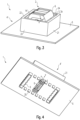
- the Figures 3 and 4 show, by way of example, a heat conducting structure 4' according to a second embodiment.
- the heat conducting structure 4' has two walls 21, 22 which are in surface contact with the transformer core 3, the transformer core 3 being arranged between these walls 21, 22.
- the heat conducting structure 4' differs from the heat conducting structure 4 in particular in that the heat conducting structure 4' has a wall which surrounds at least the transformer core 3 in a closed manner.
- the heat conducting structure 4' has further, preferably two side walls 23, 24 which the side walls 21, 22 are connected to one another so that the closed surrounding wall is created.
- the other side walls 23, 24 are preferably also in surface contact with the transformer core 3.
- the heat conducting structure 4' thus forms a closed wall which can be easily placed on the transformer coil 2 so that at the same time the wall, in particular the side walls 21, 22 and/or the side walls 23, 24, come into surface contact with the transformer core 3, in particular with its third section 3a.
- the heat conducting structure 4' is not limited to such a cross-section.
- other cross-sections are also suitable which can bring about at least surface contact with the transformer core 3, i.e. polygonal and/or round cross-sections.
- the wall of the heat conducting structure 4' thus surrounds at least the transformer core 3 in a closed manner, so that the wall covers the transformer core 3 in every side view of the transformer coil 2.
- the wall defines an opening through which the transformer coil 2 partially passes. Seen in plan view or when looking at the first side of the circuit board 5, at least a part of the transformer coil 2, preferably at least the transformer core 3 or the complete transformer coil 2, is therefore not covered or visible by the heat conducting structure 4'.
- the heat conducting structure 4' or the side walls 21-24 have a height such that, seen in side view of the transformer coil 2, the transformer core 3 is covered, but a part of the transformer coil, preferably a part of the transformer body 6, protrudes beyond the heat conducting structure 4' and is thus visible.
- the heat conducting structure 4' can have a mounting section 14' corresponding to the mounting section 14.
- the side walls 21, 22 and/or the side walls 23, 24 can be provided in such a way that the transformer core 3 at least comes into frictional connection with them, i.e. the transformer core 3 is preferably clamped between them.
- the base of the wall or the side walls 21-24, i.e. those sides of the wall which are opposite the circuit board 5, can also have the Mounting section 14'.
- the mounting section 14' can have fastening means for material, force and/or form-fitting fastening to the circuit board 5, for example a clip connection.
- the heat conducting structure 4' preferably the mounting section or base of the wall, can have several, preferably 10 to 40, particularly preferably 20 to 30, ideally 28 legs 25 for dissipating heat, preferably in the direction of the second side of the circuit board 5.
- the legs 25 can be provided on the heat conducting structure 4' or on the wall of the heat conducting structure 4' in accordance with the (closed) cross section of the wall.
- the circuit board 5 can have several openings through which one of the legs 25 passes so that the legs 25 protrude from the second side.
- the legs 25 can also be used to mount or fasten the heat conducting structure 4' on the circuit board 5, for example by the legs 25 being in positive and/or force-fit connection with the respective opening of the circuit board 5.
- the legs 25 can each be designed to be connected to a heat-dissipating and/or heat-distributing element of a lamp and/or the operating device 1.
- the heat-dissipating and/or heat-distributing element is, for example, a heat sink (not shown in detail).
- the heat-dissipating and/or heat-distributing element can also be a metallic core of the circuit board 5.
- the heat-dissipating and/or heat-distributing element can also be any other large-area component that is suitable for dissipating heat into the ambient air.
- the legs 25 do not necessarily have to pass through the circuit board 5.
- the legs 25 are provided in particular to conduct heat in an advantageous manner, in particular in the direction of a heat sink. This is intended to prevent other components, which are provided for example on the first side of the circuit board 5, from being affected.
- the legs 25 in particular increase the heat-emitting surface overall.
- the legs 25 therefore also serve as an additional heat sink in order to cool the transformer core 3 better.
- the heat conducting structure 4, 4' is preferably made of a material that is a good heat conductor. Metal, preferably copper, is particularly suitable for this purpose. and/or aluminum. However, it is also conceivable that the material alternatively or additionally comprises plastic or consists (only) of plastic, in order to thus also provide electrical insulation for the transformer coil 2, for example.
- the heat conducting structure 4, 4' is preferably designed as a unit with the coil core or transformer core 3.
- the heat conducting structure 4, 4' can also have cooling fins (not shown in detail).
- the cooling fins are preferably provided on at least one side of the heat conducting structure 4, 4' which faces away from the coil core or transformer core 3, i.e. for example on the outside of one or more, preferably each of the walls 11-13 or 21-24.
- the cooling fins are preferably provided (evenly) distributed on the surface or walls 11-13 or 21-24 of the heat conducting structure 4, 4'. It is also preferred if the cooling fins are provided on the entire surface of the heat conducting structure 4, 4', wherein this surface preferably comprises the surface of the heat conducting structure 4, 4' which faces away from the coil core, i.e.
- the invention is not limited to the previously described embodiments. In particular, all features can be combined with one another in any advantageous manner.
- the legs 25 provided according to the second embodiment can also be provided in a corresponding manner on the heat conducting structure 4.
- the heat conducting structure 4 has the closed surrounding wall or the side walls 21-24 of the heat conducting structure 4' instead of the side walls 11, 12.
Landscapes
- Engineering & Computer Science (AREA)
- Power Engineering (AREA)
- General Engineering & Computer Science (AREA)
- Microelectronics & Electronic Packaging (AREA)
- Arrangement Of Elements, Cooling, Sealing, Or The Like Of Lighting Devices (AREA)
Description
- Die Erfindung betrifft ein Betriebsgerät für eine Leuchte, insbesondere für eine LED Leuchte.
- Betriebsgeräte der eingangs genannten Art werden verwendet, um Leuchtmittel, insbesondere LEDs, zu betreiben, beispielsweise um die Leuchte mit einer bestimmten Spannung und/oder einem bestimmten Strom zu versorgen. Weitere beispielhafte Anwendungen sind die Pulsweitenmodulation, das Einstellen der Helligkeit (insbesondere Dimmen) und/oder die allgemeine Ansteuerung der Leuchtmittel. Hierfür werden unter anderem Spulen benutzt, beispielsweise in einem Transformator, um Energie bereitzustellen und/oder zu speichern, sodass die Leuchte entsprechend betrieben wird. Andere Anwendungen von Spulen in einem derartigen Betriebsgerät sind z.B. Spulen zur Leistungskorrektur (PFC), Spulen in einem LLC-Wandler/Konverter, Spulen zur Netzeingangsdrosselung, Spulen in Flyback-Konvertern oder Spulen allgemein zur Energie(zwischen)speicherung.
- Es ist bekannt, dass die Spulen oder Spulenkombinationen, beispielsweise Transformatoren, oder magnetische Komponenten im Allgemeinen nicht verlustfrei arbeiten und somit in unerwünschter Weise Wärme bzw. Abwärme abgeben. Insbesondere die Wicklungen und der Spulenkern der Spule geben dabei viel Wärme ab. Diese Wärme muss möglichst gut abgeleitet werden, sodass diese nicht andere elektrische und/oder elektronische Bauteile beeinflusst, da die unerwünscht hohen Temperaturen insbesondere die Lebensdauer des jeweiligen elektrischen und/oder elektronischen Bauteils und somit des Betriebsgeräts verkürzen kann. Vor allem kapazitive Bauteile sind für solche hohen Temperaturen empfindlich. Im Stand der Technik ist es bekannt, mittels Wärmeleitpaste, insbesondere mittels sogenannter TIM (thermal interface materials) gap pads, die Abwärme direkt auf das Gehäuse des Betriebsgeräts oder der Leuchte zu leiten. Dies ist jedoch nicht sehr effektiv und zudem verhältnismäßig teuer.
- Die
EP 1 528 577 A1 offenbart ein Betriebsmittel, das ein Kunststoffgehäuse aufweist, wobei das Kunststoffgehäuse so beschaffen ist, dass dieses Gehäuse bei allen Fertigungsmaßtoleranzen immer an dem Eisenpaket des jeweils verwendeten Spulenbauelements (Transformator oder Vorschaltdrossel) anliegt, um eine gute Wärmeableitung zu ermöglichen. - Die
DE 10 2008 048977 A1 offenbart eine elektronische Kompaktbaugruppe zur Montage auf einer Leiterplatte, mit einem Gehäuse, in dem ein Transformator angeordnet und vergossen ist. - Die
CN 104 240 926 A offenbart eine Transformatorstruktur aufweisend eine Schale, die einen Raum aufweist, eine Induktionseinheit und einen wärmeleitenden Kleber, wobei der Kleber den Raum ausfüllt, um die Induktionseinheit abzudecken. - Die
DE 198 14 897 A1 offenbart ein induktives Bauelement für hohe Leistungen, umfassend einen Ringbandkern, wobei der mit einer Wicklung versehene Kern sich in einem Metallgehäuse befindet, und die innerhalb des Metallgehäuses befindlichen Zwischenräume mit einer Gießmasse gefüllt sind, wobei der in sich geschlossene Kern durch mindestens eine stabförmige Heatpipe gekühlt wird. - Die
EP 0 432 670 A2 offenbart ein Vorschaltgerät mit einem äußeren Gehäuse mit hoher Wärmeleitfähigkeit, wobei ein Wärme abstrahlendes Teil mit zumindest einer inneren Oberfläche des Gehäuses in flächigem Kontakt ist. - Die
EP 3 319 096 A1 offenbart einen magnetischen Kern mit zumindest einer Spule und einer Kühlstruktur, die ein nichtmetallisches, wärmeleitendes Element aufweist, gebaut als Heatpipe und angeordnet im Inneren eines Lochs oder einer Kavität des Kerns. - Die
US 2002/135983 A1 offenbart ein Energie umwandelndes Gerät, aufweisend eine wärmeleitende Basis und eine wärmeleitende Abdeckung, die mit der Basis gefügt werden kann, um einen verschlossenen Raum zu bilden. - Die
DE 203 17 641 U1 offenbart Wärmeleitbrücke für Ringkern-Induktivitäten. - Die
WO 2017/154696 A1 offenbart eine Schaltungsanordnung mit einer Leiterplatte, einem Kühlkörper, der auf die Leiterplatte aufgesetzt ist, und einem Induktor. - Die
WO 2017/154954 A1 offenbart eine Schaltungsstruktur, aufweisend eine Spulenvorrichtung und einen Kühlkörper, an dem die Spulenvorrichtung gesichert ist. - Die
JP S61 105814 A - Die
US 4,082,141 A offenbart ein Vorschaltgerät mit einem thermischen Pfad. - Die
JP H05 67043 U3 - Die
DE 87 16 135 U1 offenbart einen Transformator mit einem Magnetkern, wobei Bodenbefestigungselemente vorgesehen sind, an denen senkrecht hochstehende Lappen angeformt sind, wobei Teilbereiche der Kanten der Lappen mit verschweißt werden. - Der Erfindung liegt die Aufgabe zu Grunde, die oben genannten Nachteile aus dem Stand der Technik zu beseitigen, also insbesondere die Wärme von Spulen effizienter zu leiten bzw. allgemein die Wärmeentwicklung solcher Betriebsgeräte zu optimieren.
- Die Aufgabe wird erfindungsgemäß für das Betriebsgerät durch die Merkmale des unabhängigen Anspruchs gelöst. Vorteilhafte Weiterbildungen sind Gegenstand der hierauf rückbezogenen Unteransprüche.
- Ein erfindungsgemäßes Betriebsgerät für eine Leuchte, insbesondere für eine LED Leuchte, weist auf: eine Spule mit einem Spulenkern, und eine Wärmeleitstruktur, die in flächigem Kontakt mit dem Spulenkern steht, um die von dem Spulenkern im Betrieb der Spule abgegebene Wärme von dem Spulenkern weg zu leiten.
- Mit anderen Worten erzeugt der Spulenkern im Betrieb der Spule Verlustenergie in Form von Abwärme, welche durch die in flächigem Kontakt stehende Wärmeleitstruktur effizient auf die Wärmeleitstruktur übertragen wird, wodurch der Spulenkern effizient gekühlt wird. Das heißt, durch den flächigen Kontakt der Wärmeleitstruktur mit dem Spulenkern kann die Wärme gemäß einem gewünschten, nämlich von der Wärmeleitstruktur definierten Weg - insbesondere zu einem wärmeableitenden und/oder wärmeverteilenden Element der Leuchte wie beispielsweise einem Kühlkörper der Leuchte - effizient geleitet werden. Somit wird einerseits der Spulenkern gekühlt bzw. die Wärme von diesem weggeführt, und andererseits verhindert, dass andere elektrische und/oder elektronische Bauteile oder allgemein Bauteile des Betriebsgeräts von dieser Wärme beeinflusst werden. Die Effizienz der Kühlung des Spulenkerns ist folglich verbessert. Außerdem ist somit auch die Lebensdauer bzw. Zuverlässigkeit des Betriebsgeräts erhöht, da Abwärme des Spulenkerns die Bauteile des Betriebsgeräts, insbesondere die in der Nähe der Spule befindlichen Bauteile, weniger beeinflusst. Folglich kann das Betriebsgerät auch in höheren Umgebungstemperaturen verwendet werden.
- Das Betriebsgerät weist ferner eine Leiterplatte auf, wobei die Spule mit der Wärmeleitstruktur auf einer ersten Seite der Leiterplatte derart vorgesehen ist, dass die Wärmeleitstruktur die von dem Spulenkern abgegebene Wärme von dem Spulenkern und der ersten Seite weg zu einer der ersten Seite abgewandten Seite der Leiterplatte leitet. Da auf Seiten der Spule bzw. auf der ersten Seite (Vorderseite) der Leiterplatte in der Regel empfindliche elektrische und/oder elektronische Bauteile wie beispielsweise kapazitive Bauteile vorgesehen sind, werden diese Bauteile nunmehr wegen Abführung der Wärme durch die Wärmeleitstruktur auf die zweite Seite bzw. Rückseite der Leiterplatte nicht mehr beeinflusst. Somit bleiben insbesondere die Bauteile des Betriebsgerät von der Abwärme der Spule verschont. Und da die Spule somit ebenfalls weniger ihrer Abwärme ausgesetzt ist, kann diese nunmehr in ihrer Baugröße reduziert werden.
- Bevorzugt ist, wenn der Spulenkern zwischen in flächigem Kontakt mit dem Spulenkern stehenden Wänden der Wärmeleitstruktur angeordnet ist. Somit kann die Wärmeleitstruktur einfach auf den Spulenkern gesteckt werden, um automatisch in flächigem Kontakt mit dem Spulenkern zu stehen. Zudem wird durch die in flächigem Kontakt stehenden Wände der Wärmeleitstruktur die wärmeabgebende Fläche vergrößert, sodass auch die Effizienz der Wärmeabführung bzw. Kühlung verbessert ist.
- Die Wärmeleitstruktur kann eine wenigstens den Spulenkern geschlossen umgebende Wandung sein. Einerseits kann somit die Wärmeleitstruktur beim Aufsetzen der Wärmeleitstruktur einfach, insbesondere automatisch in flächigen Kontakt mit dem Spulenkern gebracht werden. Andererseits wird die Fläche der Wärmeleitstruktur vergrößert, was wiederum der Kühlung zugutekommen. Wegen der geschlossen umgebende Wandung kann zudem eine gute Wärmisolierung der außerhalb der Wandung vorgesehenen Bauteile bewirkt werden. Außerdem kann durch die Öffnung, welche die Wandung definiert, Luft zur Spule bzw. zum Spulenkern gelangen, sodass der konvektive Wärmeübergang zwischen Luft und Spulenkern und somit die Effizienz der Kühlung verbessert ist.
- Die Wärmeleitstruktur kann eine wenigstens den Spulenkern abdeckende Haube oder Kappe sein, welche vorzugsweise einen im Wesentlichen U-förmigen Querschnitt aufweist. Durch die Öffnungen, die Haube bzw. der vorzugsweise U-förmige Querschnitt definiert, kann somit Luft strömen, um insbesondere den konvektiven Wärmeübergang innerhalb der Haube zu verbessern. Außerdem ist somit der Spulenkern nach oberhalb des Spulenkerns abgedeckt, sodass insbesondere in dieser Richtung Bauteile des Betriebsgeräts von Abwärme des Spulenkerns verschont bleiben. Außerdem ist die wärmeabführende Fläche somit vergrößert, was wiederum der effizienteren Kühlung des Spulenkerns zugutekommt. Zudem kann somit die Wärmeleitstruktur einfach auf die Spule bzw. den Spulenkern gesetzt oder gesteckt, vorzugsweise geklemmt werden.
- Vorzugsweise weist die Wärmeleitstruktur einen Montageabschnitt zur Montage der Wärmeleitstruktur in das Betriebsgerät, insbesondere auf die Leiterplatte, und/oder an die Spule auf. Durch vorzugsweise integrales Vorsehen des Montageabschnitts kann somit die Wärmeleitstruktur einfach mit dem Betriebsgerät und/oder der Spule verbunden bzw. auf diesen montiert werden, beispielsweise über eine stoff-, kraft- und/oder formschlüssige Verbindung. Bevorzugt ist, wenn die freien Enden der Haube oder der Fuß der Wandung den Montageabschnitt aufweisen bzw. aufweist, sodass die Wärmeleitstruktur besonders einfach montiert werden kann.
- Die Wärmeleitstruktur, vorzugsweise der Montageabschnitt, weist Beinchen zum Ableiten von Wärme in Richtung der zweiten Seite der Leiterplatte auf. Durch Vorsehen der Beinchen kann wiederum die wärmeabführende Fläche vergrößert werden, was wiederum dem Kühleffekt der Wärmeleitstruktur zugutekommen. Außerdem haben die Beinchen eine vorteilhafte Ausbildung, um mit anderen wärmeableitenden Elementen verbunden zu werden. Die Beinchen treten durch die Leiterplatte hindurch. Somit kann in besonders vorteilhafter Weise mittels der Beinchen bewirkt werden, dass Wärme von der Vorderseite (die erste Seite) zur Rückseite (die zweite Seite) der Leiterplatte (direkt) geleitet wird. Wegen des Hindurchtretens der Beinchen durch die Leiterplatte können die Beinchen außerdem gleichzeitig als Befestigungsmittel zur Befestigung der Wärmeleitstruktur auf der Leiterplatte genutzt werden.
- Vorzugsweise sind die Beinchen dazu augebildet, um mit einem wärmeableitenden und/oder wärmeverteilenden Element einer Leuchte und/oder des Betriebsgeräts verbunden zu werden. Somit können die Beinchen genutzt werden, um die Abwärme des Spulenkerns auf diese wärmeableitenden und/oder wärmeverteilenden Elemente direkt zu leiten, also insbesondere von wärmeempfindlichen Bauteilen des Betriebsgeräts weg zu leiten. Die Beinchen sind vorzugsweise mit einem wärmeableitenden und/oder wärmeverteilenden Element des Betriebsgeräts verbunden. Somit ist sichergestellt, dass die vom Spulenkern abgegebene und auf die Wärmeleitstruktur übertragene Wärme nur auf dieses wärmeableitende und/oder wärmeverteilende Element geleitet wird.
- Das wärmeableitende und/oder wärmeverteilende Element ist vorzugsweise ein Kühlkörper oder ein sonstiges großflächiges Bauteil zur Abgabe von Wärme. Dadurch kann die Abwärme in besonders vorteilhafter Weise von dem Betriebsgerät beispielsweise an die Umgebungsluft abgegeben werden, um somit eine effiziente Kühlung zu bewirken.
- Die Wärmeleitstruktur kann aus einem Material hergestellt sein, das Metall, vorzugsweise Kupfer und/oder Aluminium, aufweist. Diese Materialien haben eine besonders hohe Wärmeleitfähigkeit, sodass diese sich in besonders vorteilhafter Weise für eine effiziente Kühlung des Spulenkerns bzw. für die Wärmeleitung mittels der Wärmeleitstruktur eignen. Alternativ oder zusätzlich kann das Material (nur) aus (für hohe Wärmeleitung ausgelegten) Kunststoff bestehen bzw. Kunststoff aufweisen. Die Wärmeleitstruktur kann somit neben der Kühlung des Spulenkerns gleichzeitig dazu vorgesehen sein, die Spule elektrisch zu isolieren.
- In einem bevorzugten Ausführungsbeispiel ist der Spulenkern ein Ferritkern. Ferrit eignet sich in besonders vorteilhafter Weise, den magnetischen Fluss der Spule zu leiten.
- Bevorzugt ist, wenn die Wärmeleitstruktur Kühlrippen aufweist. Somit hat die Wärmeleitstruktur eine für die Wärmeabgabe bzw. für die Wärmewegleitung optimierte, also insbesondere vergrößerte Oberfläche. Die Kühlrippen sind vorzugsweise integral mit der Wärmeleitstruktur vorgesehen bzw. die Wärmeleitstruktur ist vorzugsweise derart (aus)geformt, dass sie die Kühlrippen bildet. Die Kühlrippen sind vorzugsweise wenigstens auf einer Seite der Wärmeleitstruktur vorgesehen, welche dem Spulenkern abgewandt ist, sodass die Wärme des Spulenkerns gut von dem Spulenkern weggeleitet werden kann. Vorzugsweise sind die Kühlrippen auf der Oberfläche der Wärmeleitstruktur (gleichmäßig) verteilt vorgesehen. Bevorzugt ist ferner, wenn die Kühlrippen auf der kompletten Oberfläche der Wärmeleitstruktur vorgesehen ist, wobei diese Oberfläche vorzugsweise die Oberfläche der Wärmeleitstruktur umfasst, welche dem Spulenkern abgewandt ist, und/oder die Oberfläche der Wärmeleitstruktur umfasst, welche dem Spulenkern zugewandt ist.
- Die Spule ist eine Transformatorspule, wobei der Spulenkern als Transformatorkern ausgebildet ist. Eine Transformatorspule, insbesondere dessen Transformatorkern, ist dafür bekannt, dass dieser wegen der Umwandlung von Spannung eine hohe Abwärme verursacht. Die vorgenannte Wärmeleitstruktur eignet sich daher in besonders vorteilhafter Weise, diese Abwärme effizient abzuleiten, also insbesondere den Transformator oder andere Bauteile mit der Abwärme nicht zu beeinflussen.
- Der Transformatorkern weist auf: einen ersten Abschnitt zum elektromagnetischen Zusammenwirken mit einer Primärwicklung, einen zweiten Abschnitt zum elektromagnetischen Zusammenwirken mit einer Sekundärwicklung, und einen dritten Abschnitt zum Verbinden des ersten Abschnitts mit dem zweiten Abschnitt, um den magnetischen Fluss zwischen dem ersten und dem zweiten Abschnitt zu leiten. Die Wärmeleitstruktur steht dann mit dem dritten Abschnitt in flächigem Kontakt. Da der dritte Abschnitt von jeglicher Wicklung freigelegt ist und zudem eine große wärmeabgebende Fläche aufweist, kann die Wärmeleitstruktur mit dieser (gesamten) Fläche in (voll-)flächigen Kontakt gebracht werden, was zur Verbesserung der Effizienz der Wärmeabgabe bzw. Kühlung beiträgt. Außerdem ist der dritte Abschnitt gut von außerhalb der Spule zugänglich, sodass die Wärmeleitstruktur einfach in flächigen Kontakt mit dem Transformatorkern gebracht werden kann.
- Die Erfindung betrifft ferner eine Leuchte, insbesondere eine LED-Leuchte, aufweisend ein Leuchtmittel, vorzugsweise eine LED, und ein wie oben beschriebenes Betriebsgerät zum Betrieb des Leuchtmittels.
- Nachfolgend wird die Erfindung anhand der Figuren, in denen vorteilhafte Ausführungsbeispiele der Erfindung dargestellt sind, beispielhaft beschrieben. In den Figuren zeigen:
- Figur 1
- eine schematische perspektivische Ansicht eines (Ausschnitts eines) Ausführungsbeispiels einer ersten Ausführungsform des erfindungsgemäßen Betriebsgeräts,
- Figur 2
- eine Seitenansicht des in
Figur 1 gezeigten Ausführungsbeispiels, - Figur 3
- eine schematische perspektivische Ansicht eines (Ausschnitts eines) Ausführungsbeispiels einer zweiten Ausführungsform des erfindungsgemäßen Betriebsgeräts, und
- Figur 4
- das in
Figur 3 gezeigte Betriebsgerät in einer perspektivischen Ansicht von unten. - Die nachfolgend beschriebenen Figuren zeigen beispielhaft zwei Ausführungsformen eines erfindungsgemäßen Betriebsgeräts 1. Es ist nicht das gesamte Betriebsgerät erkennbar, sondern der Einfachheit halber nur ein schematischer Ausschnitt. Das Betriebsgerät 1 findet Anwendung bei einer Leuchte, insbesondere bei einer LED-Leuchte. Mittels des Betriebsgeräts 1 kann eine Leuchte (nicht näher dargestellt) betrieben werden, insbesondere damit die Leuchte in einer gewünschten Weise Licht abgibt. Beispielhafte Anwendungen des Betriebsgeräts 1 sind die Versorgung mit Spannung und/oder Strom, Pulsweitenmodulation, das Einstellen der Helligkeit (insbesondere Dimmen) und/oder die allgemeine Ansteuerung der Leuchtmittel.
- Wie in den Figuren erkennbar, weist das Betriebsgerät 1 eine Transformatorspule 2 mit einem Transformatorkern 3 auf, wobei eine Wärmeleitstruktur 4, 4' im flächigem Kontakt mit dem Transformatorkern 3 steht, um den Transformatorkern 3 zu kühlen bzw. um die von dem Transformaterkern 3 im Betrieb des Transformators bzw. der Transformatorspule 2 abgegebene Wärme von dem Transformaterkern 3 weg zu leiten.
- Die Wärmeleitstruktur 4, 4' ist jedoch nicht auf eine Transformatorspule 2 mit Transformatorkern 3 beschränkt. Vielmehr eignet sich die Wärmeleitstruktur 4, 4' für jegliche in einem Betriebsgerät zur Anwendung kommende Spule mit Spulenkern. Beispiele sind Spulen zur Leistungskorrektur (PFC), Spulen in einem LLC-Wandler/Konverter, Spulen zur Netzeingangsdrosselung, Spulen in Flyback-Konvertern oder Spulen allgemein zur Energie(zwischen)speicherung. Die Beschreibung gilt somit in analoger Weise allgemein für eine Spule mit einem Spulenkern.
- In den Figuren ist erkennbar, dass die Transformatorspule 2 einen Transformatorkern 3 und einen Transformatorkörper 6 aufweist. Der Transformatorkern 3 ist beispielsweise aus Ferrit hergestellt, kann jedoch aus jedem anderen Material hergestellt sein, dass sich zur Leitung von magnetischem Fluss eignet. Der Transformatorkern 2 weist einen ersten Abschnitt zum elektromagnetischen Zusammenwirken mit einer Primärwicklung, und einen zweiten Abschnitt zum elektromagnetischen Zusammenwirken mit einer Sekundärwicklung auf. Diese sind vorzugsweise in dem Transformatorkörper 6 aufgenommen und somit nicht sichtbar. Die mit dem Transformatorkern 3 zusammenwirkenden Wicklungen bewirken, dass Spannung umgewandelt wird, insbesondere von einer hohen Spannung auf der Primärwicklungsseite zu einer niedrigeren Spannung auf der Sekundärwicklungsseite, wobei letztere in der Regel zum Betreiben des Leuchtmittels mit der niedrigeren Spannung vorgesehen ist. Erkennbar ist ferner ein dritter Abschnitt 3a, der den ersten Abschnitt mit dem zweiten Abschnitt verbindet, um den magnetischen Fluss zwischen dem ersten und dem zweiten Abschnitt zu leiten. Der dritte Abschnitt 3a ist nicht im Transformatorkörper 6 vorgesehen und somit für die Wärmeleitstruktur 4 gut zugänglich. Das heißt, beim Aufsetzen der Wärmeleitstruktur 4 auf die Transformatorspule 2 gelangt die Wärmeleitstruktur 4 vorzugsweise (nur) in flächigen Kontakt mit dem dritten Abschnitt 3a.
- Das Betriebsgerät 1 kann ferner eine Leiterplatte (PCB) 5 aufweisen, wobei die Transformatorspule 2 mit der Wärmeleitstruktur 4, 4' auf einer ersten Seite bzw. auf der Vorderseite der Leiterplatte 5 vorgesehen ist. Wie in
Figur 4 gut erkennbar, kann die Leiterplatte 5 insbesondere eine Öffnung aufweisen, über welche von der Rückseite der Leiterplatte 5 aus ein Anschluss 8 der Transformatorspule 2 zum Verbinden eines Leuchtmittels und/oder einer Spannungsquelle mit der Transformatorspule 2 zugänglich ist. Zudem ist inFigur 4 erkennbar, dass die Transformatorspule 2 mehrere Pins 9 aufweisen kann, welche bevorzugt durch die Leiterplatte 9 hindurchtreten und die Transformatorspule 2 mit elektrischen und/oder elektronischen Bauteilen der Leiterplatte elektrisch verbindet. - Im Allgemeinen hat die Wärmeleitstruktur 4, 4' vorzugsweise eine Ausgestaltung, dass die Wärmeleitstruktur 4, 4' die von dem Transformatorkern 3 abgegebene Wärme von dem Transformatorkern 3 und der ersten Seite bzw. der Vorderseite der Leiterplatte 5 weg zu einer der ersten Seite abgewandten zweiten Seite bzw. zur Rückseite der Leiterplatte 5 leitet. Somit wird die Abwärme, welche im Betrieb der Transformatorspule 2 abgegeben wird, von Bauteilen, die auf der ersten Seite der Leiterplatte 5 vorgesehen sind, in vorteilhafter Weise weg geleitet, insbesondere derart, dass die von dem Transformatorkern 3 abgegebene Wärme diese Bauteile nicht beeinflusst.
- In den
Figuren 1 und 2 ist beispielhaft eine Wärmeleitstruktur 4 gemäß einer ersten Ausführungsform. Erkennbar ist, dass die Wärmeleitstruktur 4 zwei Wände 11, 12 aufweist, die jeweils in flächigem Kontakt mit dem Transformatorkern 3, vorzugsweise mit dessen dritten Abschnitt 3a, stehen, wobei der Transformatorkern 3 zwischen den Wänden 11, 12 angeordnet ist. Ferner ist erkennbar, dass diese Anordnung beispielsweise erfolgt, indem die Wärmeleitstruktur 4 als eine Haube ausgebildet ist, die in einer Draufsicht und/oder wenigstens einer Seitenansicht, vorzugsweise in zwei Seitenansichten, der Transformatorspule 2 gesehen wenigstens den Transformatorkern 3 und vorzugsweise die komplette Transformatorspule 2 abdeckt. Die Wärmeleitstruktur 4 kann ferner eine weitere Seitenwand 13 aufweisen, welche wenigstens den Transformatorkern 3 und vorzugsweise die Transformatorspule 2 in Draufsicht der Transformatorspule 2 gesehen abdeckt. Die weitere Seitenwand 13 ist vorzugsweise vorgesehen, um in Kontakt mit dem Transformatorkörper 6 zu stehen. Somit kann die Wärmeleitstruktur 4 in einem die Seitenwände 11, 12, 13 aufweisenden Schnitt gesehen einen im Wesentlichen U-förmigen Querschnitt aufweisen. Die Wärmeleitstruktur 4 bildet somit eine Haube, welche einfach auf den Transformatorspule 2 aufsetzbar ist, sodass gleichzeitig die Haube, insbesondere die Seitenwände 11, 12, in flächigen Kontakt mit dem Transformatorkern 3, insbesondere mit dessen dritten Abschnitt 3a, gelangen. - Die Wärmeleitstruktur 4 ist vorzugsweise in einer weiteren Seitenansicht, vorzugsweise in zwei weiteren Seitenansichten, der Transformatorspule 2 gesehen (vgl. beispielsweise
Figur 2 ) geöffnet, sodass durch diese Öffnung(en) wenigstens ein Teil der Transformatorspule 2, vorzugsweise wenigstens der Transformatorkern 3 oder die komplette Transformatorspule 2, durch die Wärmeleitstruktur 4 nicht abgedeckt bzw. sichtbar ist. Durch diese beiden Öffnungen kann somit beispielsweise Luft strömen, um den Kühleffekt insbesondere durch konvektiven Wärmeübergang in vorteilhafter Weise zu unterstützen. Es kann jedoch auch vorgesehen sein, dass die Wärmeleitstruktur 4 bzw. die Haube die Transformatorspule 2 in allen Seitenansichten und in der Draufsicht abdeckt, um somit die Fläche der Wärmeleitstruktur 4 zur Kühlung noch weiter zu vergrößern. - Wie in
Figur 2 erkennbar, kann die Transformatorspule 2 ferner Beinchen 7 aufweisen, welche durch die Leiterplatte 5 hindurchtreten. Vorzugsweise weist der Spulenkörper 6 die Beinchen 7 auf. In dem hier dargestellten Ausführungsbeispiel sind mehrere, vorzugsweise fünf der Beinchen 7 vorgesehen. In entsprechender Weise kann die Leiterplatte 5 mehrere, vorzugsweise fünf Öffnungen aufweisen, durch welche jeweils eines der Beinchen 7 hindurchtritt. Die Beinchen 7 sind vorgesehen, um die wärmeabgebende Fläche insgesamt zu vergrößern, also als Wärmesenke zu dienen, sodass der Transformatorkern 3 besser gekühlt wird. Die Beinchen 7 können mit dem Spulenkörper 6, insbesondere mit einem Bereich des Spulenkörpers 6, welcher auf der Leiterplatte 5 aufliegt, mittels kraft- und/oder formschlüssigen Mitteln wie beispielsweise einer Clipsverbindung verbunden werden. Die Beinchen 7 weisen vorzugsweise eine derartige Ausbildung auf, dass diese mit einem wärmeableitenden und/oder wärmeverteilenden Element der Leuchte und/oder des Betriebsgeräts 1 verbunden werden können. Ein Beispiel für ein solches wärmeableitendes und/oder wärmeverteilendes Element ist ein nicht näher dargestellter Kühlkörper. Das wärmeableitende und/oder wärmeverteilende Element kann auch ein metallischer Kern der Leiterplatte 5 sein. Das vorgenannte Element kann jedoch auch jedes sonstige großflächige Bauteil zur Abgabe von Wärme an die Umgebungsluft sein. - Bevorzugt ist, wenn die freien Enden der Haube bzw. die distalen Enden der Wände 11, 12 jeweils wie oben beschriebene Beinchen aufweisen, um die Abwärme des Transformatorkerns 3 abzuleiten. Das für die Beinchen 7 Gesagte gilt somit für die Beinchen der freien Enden der Haube analog.
- Die Wärmeleitstruktur 4 kann ferner einen Montageabschnitt 14 aufweisen, um die Wärmeleitstruktur 4 in dem Betriebsgerät 1 zu montieren bzw. zu befestigen. Hierfür kann der Montageabschnitt 14 jegliche Befestigungsmittel aufweisen, welche eine stoff-, kraft- und/oder formschlüssigen Befestigung zwischen Wärmeleitstruktur 4 und Transformatorkern 3 bewirken können, beispielsweise eine Clipsverbindung. Vorzugsweise sind die Wände 11, 12 derart vorgesehen, dass der Transformatorkern 3 mit den Wänden 11, 12 wenigstens in Kraftschluss kommt, also der Transformatorkern 3 beispielsweise zwischen den Wänden 11, 12 geklemmt ist. Alternativ oder zusätzlich kann auch das freie bzw. distale Ende der Seitenwände 11, 12, also jene Seiten der Seitenwände 11, 12, welche der Leiterplatte 5 gegenüberliegen, den Montageabschnitt 14 aufweisen.
- Die
Figuren 3 und 4 zeigen beispielhaft eine Wärmeleitstruktur 4' gemäß einer zweiten Ausführungsform. Die Wärmeleitstruktur 4' weist zwei Wände 21, 22 auf, die in flächigem Kontakt mit dem Transformatorkern 3 stehen, wobei der Transformatorkern 3 zwischen diesen Wänden 21, 22 angeordnet ist. Die Wärmeleitstruktur 4' unterscheidet sich von der Wärmeleitstruktur 4 insbesondere dahingehend, dass die Wärmeleitstruktur 4' eine Wandung aufweist, welche wenigstens den Transformatorkern 3 geschlossen umgibt. Das heißt, die Wärmeleitstruktur 4' weist weitere, vorzugsweise zwei Seitenwände 23, 24 auf, welche die Seitenwände 21, 22 miteinander verbinden, sodass sich die geschlossen umgebende Wandung ergibt. Die weiteren Seitenwände 23, 24 stehen vorzugsweise auch in flächigem Kontakt mit dem Transformatorkern 3. Die Wärmeleitstruktur 4' bildet somit eine geschlossene Wandung, welche einfach auf die Transformatorspule 2 aufsetzbar ist, sodass gleichzeitig die Wandung, insbesondere die Seitenwände 21, 22 und/oder die Seitenwände 23, 24, in flächigen Kontakt mit dem Transformatorkern 3, insbesondere mit dessen dritten Abschnitt 3a, gelangen. Somit ergibt sich in Draufsicht der Wärmeleitstruktur 4' bzw. der Transformatorspule 2 gesehen ein im Wesentlichen rechteckiger Querschnitt der Wärmeleitstruktur 4'. Die Wärmeleitstruktur 4' ist jedoch nicht auf einen derartigen Querschnitt beschränkt. Insbesondere sind auch andere Querschnitte geeignet, welche wenigstens einen flächigen Kontakt mit dem Transformatorkern 3 bewirken können, also mehreckige und/oder runde Querschnitte. - Die Wandung der Wärmeleitstruktur 4' umgibt also wenigstens den Transformatorkern 3 geschlossen, sodass die Wandung in jeder Seitenansicht der Transformatorspule 2 den Transformatorkern 3 abdeckt. Die Wandung definiert eine Öffnung, durch welche die Transformatorspule 2 teilweise hindurchtritt. In Draufsicht bzw. bei Blick auf die erste Seite der Leiterplatte 5 gesehen ist somit wenigstens ein Teil der Transformatorspule 2, vorzugsweise wenigstens der Transformatorkern 3 oder die komplette Transformatorspule 2, durch die Wärmeleitstruktur 4' nicht abgedeckt bzw. sichtbar ist. Vorzugsweise weist die Wärmeleitstruktur 4' bzw. die Seitenwände 21-24 eine Höhe auf, sodass in Seitenansicht der Transformatorspule 2 gesehen der Transformatorkern 3 verdeckt ist, aber ein Teil der Transformatorspule, vorzugsweise ein Teil des Transformatorkörpers 6, über die Wärmeleitstruktur 4' hervorsteht und somit sichtbar ist.
- Zur Montage der Wärmeleitstruktur 4' in dem Betriebsgerät 1 bzw. an die Transformatorspule 2 kann die Wärmeleitstruktur 4' einen dem Montageabschnitt 14 entsprechenden Montageabschnitt 14' aufweisen. Das für den Montageabschnitt 14 Gesagte gilt also für den Montageabschnitt 14' der Wärmeleitstruktur 4' analog. Insbesondere können die Seitenwände 21, 22 und/oder die Seitenwände 23, 24 derart vorgesehen sein, dass der Transformatorkern 3 wenigstens in Kraftschluss mit diesen gelangt, also der Transformatorkern 3 zwischen diesen vorzugsweise geklemmt ist. Alternativ oder zusätzlich kann auch der Fuß der Wandung bzw. der Seitenwände 21-24, also jene Seiten der Wandung, welche der Leiterplatte 5 gegenüberliegen, den Montageabschnitt 14' aufweisen. Der Montageabschnitt 14' kann Befestigungsmittel zur stoff-, kraft-, und/oder formschlüssigen Befestigung mit der Leiterplatte 5 aufweisen, beispielsweise eine Clipsverbindung.
- Wie insbesondere in
Figur 4 gut erkennbar, kann die Wärmeleitstruktur 4', vorzugsweise der Montageabschnitt bzw. Fuß der Wandung, mehrere, vorzugsweise 10 bis 40, besonders bevorzugt 20 bis 30, idealerweise 28 Beinchen 25 zum Ableiten von Wärme, vorzugsweise in Richtung der zweiten Seite der Leiterplatte 5, aufweisen. Erkennbar ist, dass die Beinchen 25 entsprechend dem (geschlossenen) Querschnitt der Wandung auf der Wärmeleitstruktur 4' bzw. auf der Wandung der Wärmeleitstruktur 4' vorgesehen sein können. In entsprechender Weise kann die Leiterplatte 5 mehrere Öffnungen aufweisen, durch welche jeweils eines der Beinchen 25 hindurchtritt, sodass die Beinchen 25 von der zweiten Seite hervorstehen. Dadurch können die Beinchen 25 auch zur Montage bzw. Befestigung der Wärmeleitstruktur 4' auf der Leiterplatte 5 verwendet werden, beispielsweise indem die Beinchen 25 jeweils in Form- und/oder Kraftschluss mit der jeweiligen Öffnung der Leiterplatte 5 steht. Die Beinchen 25 können jeweils ausgebildet sein, um mit einem wärmeableitenden und/oder wärmeverteilenden Element einer Leuchte und/oder des Betriebsgeräts 1 verbunden zu werden. Das wärmeableitenden und/oder wärmeverteilende Element ist beispielsweise ein nicht näher dargestellter Kühlkörper. Das wärmeableitende und/oder wärmeverteilende Element kann auch ein metallischer Kern der Leiterplatte 5 sein. Das wärmeableitende und/oder wärmeverteilende Element kann jedoch auch jedes sonstige großflächige Bauteil sein, welches für die Abgabe von Wärme an die Umgebungsluft geeignet ist. - Die Beinchen 25 müssen jedoch nicht zwangsläufig durch die Leiterplatte 5 hindurchtreten. Die Beinchen 25 sind insbesondere vorgesehen, um Wärme in vorteilhafter Weise zu leiten, insbesondere in Richtung eines Kühlkörpers. Somit soll verhindert werden, dass andere Bauteile, die beispielsweise auf der ersten Seite der Leiterplatte 5 vorgesehen sind, beeinträchtigt werden. Durch die Beinchen 25 wird insbesondere die wärmeabgebende Fläche insgesamt vergrößert. Somit dienen die Beinchen 25 außerdem als zusätzliche Wärmesenke, um den Transformatorkern 3 besser zu kühlen.
- Die Wärmeleitstruktur 4, 4' ist vorzugsweise aus einem Material hergestellt, das gut wärmeleitend ist. Hierfür eignet sich insbesondere Metall, vorzugsweise Kupfer und/oder Aluminium. Es ist jedoch auch denkbar, dass das Material alternativ oder zusätzlich Kunststoff aufweist oder (nur) aus Kunststoff besteht, um somit beispielsweise auch eine elektrische Isolation Transformatorspule 2 zu bewirken. Vorzugsweise ist die Wärmeleitstruktur 4, 4' als Einheit mit dem Spulenkern bzw. Transformatorkern 3 ausgebildet.
- Die Wärmeleitstruktur 4, 4' kann ferner nicht näher dargestellte Kühlrippen aufweisen. Die Kühlrippen sind vorzugsweise wenigstens auf einer Seite der Wärmeleitstruktur 4, 4' vorgesehen, welche dem Spulenkern bzw. Tranformatorkern 3 abgewandt ist, also beispielsweise auf der Außenseite einer oder mehrerer, vorzugsweise jeder der Wände 11-13 bzw. 21-24. Vorzugsweise sind die Kühlrippen auf der Oberfläche bzw. der Wände 11-13 bzw. 21-24 der Wärmeleitstruktur 4,4' (gleichmäßig) verteilt vorgesehen. Bevorzugt ist ferner, wenn die Kühlrippen auf der kompletten Oberfläche der Wärmeleitstruktur 4, 4' vorgesehen ist, wobei diese Oberfläche vorzugsweise die Oberfläche der Wärmeleitstruktur 4, 4' umfasst, welche dem Spulenkern abgewandt ist, also insbesondere die Außenseite einer oder mehrerer, vorzugsweise jeder der Wände 11-13 bzw. 21-24, und/oder die Oberfläche der Wärmeleitstruktur 4, 4' umfasst, welche dem Spulenkern zugewandt ist, also insbesondere die zum Spulenkern gerichtete (Innen)Seite einer oder mehrerer, vorzugsweise jeder der Wände 11-13 bzw. 21-24.
- Die Erfindung ist nicht auf die zuvor beschriebenen Ausführungsbeispiele beschränkt. Insbesondere lassen sich alle Merkmale in beliebig vorteilhafter Weise miteinander kombinieren. Insbesondere können die gemäß der zweiten Ausführungsform vorgesehenen Beinchen 25 auch in entsprechender Weise auf der Wärmeleitstruktur 4 vorgesehen sein. Zudem kann vorgesehen sein, dass die Wärmeleitstruktur 4 anstatt der Seitenwände 11, 12 die geschlossen umgebende Wandung bzw. die Seitenwände 21-24 der Wärmeleitstruktur 4' aufweist.
Claims (11)
- Betriebsgerät (1) für eine Leuchte, insbesondere für eine LED-Leuchte,
wobei das Betriebsgerät (1) aufweist:eine Spule (2) mit einem Spulenkern (3),eine Wärmeleitstruktur (4, 4'), die in flächigem Kontakt mit dem Spulenkern (3) steht, um die von dem Spulenkern (3) im Betrieb der Spule (2) abgegebene Wärme von dem Spulenkern (3) weg zu leiten, undeine Leiterplatte (5),wobei die Spule (2) mit der Wärmeleitstruktur (4,4') auf einer ersten Seite der Leiterplatte (5) derart vorgesehen ist, dass die Wärmeleitstruktur (4, 4') die von dem Spulenkern (3) abgegebene Wärme von dem Spulenkern (3) und der ersten Seite weg zu einer der ersten Seite abgewandten zweiten Seite der Leiterplatte (5) leitet, undwobei die Wärmeleitstruktur (4, 4') Beinchen (25) zum Ableiten von Wärme in Richtung der zweiten Seite der Leiterplatte (5), aufweist,dadurch gekennzeichnet, dassdie Beinchen (25) durch die Leiterplatte hindurchtreten, wobei die Spule (2) eine Transformatorspule ist, und wobei der Spulenkern (3) als Transformatorkern ausgebildet ist,wobei der Transformatorkern (3) aufweist:einen ersten Abschnitt zum elektromagnetischen Zusammenwirken mit einer Primärwicklung,einen zweiten Abschnitt zum elektromagnetischen Zusammenwirken mit einer Sekundärwicklung, undeinen dritten Abschnitt (3a) zum Verbinden des ersten Abschnitts mit dem zweiten Abschnitt, um den magnetischen Fluss zwischen dem ersten und dem zweiten Abschnitt zu leiten,wobei die Wärmeleitstruktur (4, 4') mit dem dritten Abschnitt (3a) in flächigem Kontakt steht. - Betriebsgerät (1) nach Anspruch 1, wobei der Spulenkern (3) zwischen in flächigem Kontakt mit dem Spulenkern (3) stehenden Wänden (11, 12;21, 22, 23, 24) der Wärmeleitstruktur (4, 4') angeordnet ist.
- Betriebsgerät (1) nach einem der vorhergehenden Ansprüche, wobei die Wärmeleitstruktur (4') eine wenigstens den Spulenkern (3) geschlossen umgebende Wandung (21, 22, 23, 24) ist.
- Betriebsgerät (1) nach einem der vorhergehenden Ansprüche, wobei die Wärmeleitstruktur (4) eine wenigstens den Spulenkern (3) abdeckende Haube ist, welche vorzugsweise einen im Wesentlichen U-förmigen Querschnitt aufweist.
- Betriebsgerät (1) nach einem der vorhergehenden Ansprüche, wobei die Wärmeleitstruktur (4,4') einen Montageabschnitt zur Montage der Wärmeleitstruktur (4,4') in das Betriebsgerät (1), insbesondere auf die Leiterplatte (5), und/oder an die Spule (2) aufweist, wobei vorzugsweise die freien Enden der Haube oder der Fuß der Wandung (21, 22, 23, 24) den Montageabschnitt aufweist.
- Betriebsgerät (1) nach einem der Ansprüche 1 bis 5, wobei die Beinchen (25) ausgebildet sind, um mit einem wärmeableitenden und/oder wärmeverteilenden Element einer Leuchte und/oder des Betriebsgeräts verbunden zu werden, wobei die Beinchen (25) vorzugsweise mit einem wärmeableitenden und/oder wärmeverteilenden Element des Betriebsgeräts verbunden sind.
- Betriebsgerät (1) nach Anspruch 6, wobei das wärmeableitende und/oder wärmeverteilende Element ein Kühlkörper oder ein sonstiges großflächiges Bauteil zur Abgabe von Wärme ist.
- Betriebsgerät (1) nach einem der vorhergehenden Ansprüche, wobei die Wärmeleitstruktur (4, 4') aus einem Material hergestellt ist, das Metall, vorzugsweise Kupfer und/oder Aluminium, und/oder Kunststoff aufweist.
- Betriebsgerät (1) nach einem der vorhergehenden Ansprüche, wobei der Spulenkern (3) ein Ferritkern ist.
- Betriebsgerät (1) nach einem der vorhergehenden Ansprüche, wobei die Wärmeleitstruktur (4, 4') Kühlrippen aufweist.
- Leuchte, insbesondere LED-Leuchte, aufweisend ein Leuchtmittel, vorzugsweise eine LED, und ein Betriebsgerät (1) nach einem der vorhergehenden Ansprüche zum Betrieb des Leuchtmittels, wobei die Wärmeleitstruktur (4, 4') vorzugsweise mit einem wärmeableitenden und/oder wärmeverteilenden Element der Leuchte wie beispielsweise einem Kühlkörper der Leuchte verbunden ist.
Applications Claiming Priority (1)
| Application Number | Priority Date | Filing Date | Title |
|---|---|---|---|
| DE202018103181.3U DE202018103181U1 (de) | 2018-06-07 | 2018-06-07 | Betriebsgerät mit Wärmeleitstruktur |
Publications (2)
| Publication Number | Publication Date |
|---|---|
| EP3578880A1 EP3578880A1 (de) | 2019-12-11 |
| EP3578880B1 true EP3578880B1 (de) | 2025-01-01 |
Family
ID=66676203
Family Applications (1)
| Application Number | Title | Priority Date | Filing Date |
|---|---|---|---|
| EP19176075.0A Active EP3578880B1 (de) | 2018-06-07 | 2019-05-23 | Betriebsgerät mit wärmeleitstruktur |
Country Status (3)
| Country | Link |
|---|---|
| EP (1) | EP3578880B1 (de) |
| AT (1) | AT17783U1 (de) |
| DE (1) | DE202018103181U1 (de) |
Families Citing this family (1)
| Publication number | Priority date | Publication date | Assignee | Title |
|---|---|---|---|---|
| DE102021202286A1 (de) | 2021-03-09 | 2022-09-15 | Robert Bosch Gesellschaft mit beschränkter Haftung | Batteriemodulelement, Verfahren zur Herstellung eines solchen und Batteriemodul |
Citations (6)
| Publication number | Priority date | Publication date | Assignee | Title |
|---|---|---|---|---|
| US4082141A (en) * | 1976-02-18 | 1978-04-04 | Crouse-Hinds Company | Ballast vibration isolation system with thermal path |
| JPS61105814A (ja) * | 1984-10-29 | 1986-05-23 | Matsushita Electric Ind Co Ltd | 電磁装置 |
| DE8716135U1 (de) * | 1987-12-05 | 1988-02-11 | Ceag Licht- Und Stromversorgungstechnik Gmbh, 4770 Soest | Transformator, Drossel und dgl. |
| JPH0567043U (ja) * | 1992-02-15 | 1993-09-03 | 松下電工株式会社 | 実装部品の保持構造 |
| WO2017154954A1 (ja) * | 2016-03-09 | 2017-09-14 | 株式会社オートネットワーク技術研究所 | 回路構成体 |
| WO2017154696A1 (ja) * | 2016-03-10 | 2017-09-14 | 株式会社オートネットワーク技術研究所 | 回路構成体 |
Family Cites Families (10)
| Publication number | Priority date | Publication date | Assignee | Title |
|---|---|---|---|---|
| US5107186A (en) * | 1989-12-12 | 1992-04-21 | Olympus Optical Co., Ltd. | Converter and discharge-lamp operating apparatus using the converter |
| DE19814897C2 (de) * | 1998-04-02 | 2000-09-21 | Vacuumschmelze Gmbh | Induktives Bauelement für hohe Leistungen |
| US20020135983A1 (en) * | 2001-03-20 | 2002-09-26 | Christpher Freitas | Energy conversion apparatus |
| DE10350617B3 (de) * | 2003-10-30 | 2005-06-30 | Vossloh-Schwabe Deutschland Gmbh | Versorgungseinheit für Leuchtmittel |
| DE20317641U1 (de) * | 2003-11-14 | 2004-01-15 | Vacuumschmelze Gmbh & Co. Kg | Wärmeleitbrücke für Ringkern-Induktivitäten |
| DE102008048977B4 (de) * | 2008-09-25 | 2019-10-10 | Wilo Se | Elektronische Kompaktbaugruppe |
| CN104240926A (zh) * | 2009-02-18 | 2014-12-24 | 台达电子工业股份有限公司 | 变压器结构 |
| EP3319096A1 (de) * | 2016-11-07 | 2018-05-09 | Premo, S.L. | Kompakte magnetische antriebseinheit |
| CN207381240U (zh) * | 2017-07-22 | 2018-05-18 | 佛山市南海区奥志五金制品有限公司 | 一种散热性能强的变压器铁芯 |
| CN107799282A (zh) * | 2017-11-01 | 2018-03-13 | 深圳市英大科特技术有限公司 | 一种散热高频变压器、电抗器和电力电子装置 |
-
2018
- 2018-06-07 DE DE202018103181.3U patent/DE202018103181U1/de not_active Expired - Lifetime
- 2018-12-04 AT ATGM50225/2018U patent/AT17783U1/de not_active IP Right Cessation
-
2019
- 2019-05-23 EP EP19176075.0A patent/EP3578880B1/de active Active
Patent Citations (6)
| Publication number | Priority date | Publication date | Assignee | Title |
|---|---|---|---|---|
| US4082141A (en) * | 1976-02-18 | 1978-04-04 | Crouse-Hinds Company | Ballast vibration isolation system with thermal path |
| JPS61105814A (ja) * | 1984-10-29 | 1986-05-23 | Matsushita Electric Ind Co Ltd | 電磁装置 |
| DE8716135U1 (de) * | 1987-12-05 | 1988-02-11 | Ceag Licht- Und Stromversorgungstechnik Gmbh, 4770 Soest | Transformator, Drossel und dgl. |
| JPH0567043U (ja) * | 1992-02-15 | 1993-09-03 | 松下電工株式会社 | 実装部品の保持構造 |
| WO2017154954A1 (ja) * | 2016-03-09 | 2017-09-14 | 株式会社オートネットワーク技術研究所 | 回路構成体 |
| WO2017154696A1 (ja) * | 2016-03-10 | 2017-09-14 | 株式会社オートネットワーク技術研究所 | 回路構成体 |
Also Published As
| Publication number | Publication date |
|---|---|
| EP3578880A1 (de) | 2019-12-11 |
| DE202018103181U1 (de) | 2019-09-10 |
| AT17783U1 (de) | 2023-02-15 |
Similar Documents
| Publication | Publication Date | Title |
|---|---|---|
| EP2396590B1 (de) | Leuchtvorrichtung | |
| DE60119927T2 (de) | Elektronisches vorschaltgerät für eine entladungslampe | |
| EP2198196B1 (de) | Lampe | |
| DE202012104495U1 (de) | LED-Birne mit der Möglichkeit zur Erhöhung der Wärmeabführleistung | |
| DE4040690A1 (de) | Lampenvorschaltgeraet | |
| EP2142847A1 (de) | Halbleiterlichtmodul | |
| DE202010009679U1 (de) | Eine LED-Beleuchtungseinrichtung | |
| EP2507548B1 (de) | Retrofit led-lampe | |
| EP2807908A1 (de) | Vorrichtung, insbesondere schaltschrank, mit gehäuse | |
| DE20214919U1 (de) | Seitlich strahlende Leuchtdiodenstruktur | |
| DE69021845T2 (de) | Vorschaltgerät und Apparat zur Steuerung einer Entladungslampe, der dieses Vorschaltgerät benutzt. | |
| AT17783U1 (de) | Betriebsgerät mit Wärmeleitstruktur | |
| DE102006000169A1 (de) | Entladungslampen-Beleuchtungsgerät | |
| WO2011157635A1 (de) | Explosionsgeschütztes leuchtmittel | |
| DE102009060123B4 (de) | Elektrische Schaltung mit mindestens einer Leiterplatte und einer Anzahl von mit Bauelementekontaktierungen versehener elektrischer Bauelemente | |
| DE102013105120B4 (de) | Elektrische und induktive Bauteile | |
| DE102011006749A1 (de) | Lampenvorrichtung | |
| EP0150799B1 (de) | Montageeinheit für Leuchstofflampen | |
| DE19928576C2 (de) | Oberflächenmontierbares LED-Bauelement mit verbesserter Wärmeabfuhr | |
| DE102017109836B4 (de) | Leuchtmittel mit Kühlkörper | |
| EP2443389A1 (de) | Kühlkörper für halbleiterleuchtelemente | |
| DE10226607A1 (de) | Entladungslampenvorrichtung und Projektor, der diese verwendet | |
| DE102008048977B4 (de) | Elektronische Kompaktbaugruppe | |
| DE3828853A1 (de) | Kuehleinrichtung fuer elektronische bauelemente | |
| EP1470586B1 (de) | Leistungs-halbleiter, und verfahen zu seiner herstellung |
Legal Events
| Date | Code | Title | Description |
|---|---|---|---|
| PUAI | Public reference made under article 153(3) epc to a published international application that has entered the european phase |
Free format text: ORIGINAL CODE: 0009012 |
|
| STAA | Information on the status of an ep patent application or granted ep patent |
Free format text: STATUS: THE APPLICATION HAS BEEN PUBLISHED |
|
| AK | Designated contracting states |
Kind code of ref document: A1 Designated state(s): AL AT BE BG CH CY CZ DE DK EE ES FI FR GB GR HR HU IE IS IT LI LT LU LV MC MK MT NL NO PL PT RO RS SE SI SK SM TR |
|
| AX | Request for extension of the european patent |
Extension state: BA ME |
|
| STAA | Information on the status of an ep patent application or granted ep patent |
Free format text: STATUS: REQUEST FOR EXAMINATION WAS MADE |
|
| 17P | Request for examination filed |
Effective date: 20200515 |
|
| RBV | Designated contracting states (corrected) |
Designated state(s): AL AT BE BG CH CY CZ DE DK EE ES FI FR GB GR HR HU IE IS IT LI LT LU LV MC MK MT NL NO PL PT RO RS SE SI SK SM TR |
|
| STAA | Information on the status of an ep patent application or granted ep patent |
Free format text: STATUS: EXAMINATION IS IN PROGRESS |
|
| 17Q | First examination report despatched |
Effective date: 20201112 |
|
| RIC1 | Information provided on ipc code assigned before grant |
Ipc: H05K 7/20 20060101ALI20240521BHEP Ipc: H01F 27/28 20060101ALI20240521BHEP Ipc: H01F 27/06 20060101ALI20240521BHEP Ipc: H01F 27/02 20060101ALI20240521BHEP Ipc: H05B 33/00 20060101ALI20240521BHEP Ipc: H01F 27/26 20060101ALI20240521BHEP Ipc: H01F 27/25 20060101ALI20240521BHEP Ipc: H01F 27/08 20060101ALI20240521BHEP Ipc: F21V 23/02 20060101ALI20240521BHEP Ipc: F21V 23/00 20150101AFI20240521BHEP |
|
| GRAP | Despatch of communication of intention to grant a patent |
Free format text: ORIGINAL CODE: EPIDOSNIGR1 |
|
| STAA | Information on the status of an ep patent application or granted ep patent |
Free format text: STATUS: GRANT OF PATENT IS INTENDED |
|
| INTG | Intention to grant announced |
Effective date: 20240805 |
|
| RAP3 | Party data changed (applicant data changed or rights of an application transferred) |
Owner name: ZUMTOBEL LIGHTING GMBH Owner name: TRIDONIC GMBH & CO KG |
|
| RIN1 | Information on inventor provided before grant (corrected) |
Inventor name: ZENGERLE, THOMAS Inventor name: FAVAROLO, DR. ANGELO Inventor name: ALLGAIER, DOMINIK Inventor name: STEINER, SASCHA Inventor name: SCHMOELZER, ANDREAS Inventor name: SACCAVINI, LUKAS Inventor name: ROMANO, FABIO Inventor name: MAYRHOFER, MARKUS |
|
| GRAS | Grant fee paid |
Free format text: ORIGINAL CODE: EPIDOSNIGR3 |
|
| GRAA | (expected) grant |
Free format text: ORIGINAL CODE: 0009210 |
|
| STAA | Information on the status of an ep patent application or granted ep patent |
Free format text: STATUS: THE PATENT HAS BEEN GRANTED |
|
| AK | Designated contracting states |
Kind code of ref document: B1 Designated state(s): AL AT BE BG CH CY CZ DE DK EE ES FI FR GB GR HR HU IE IS IT LI LT LU LV MC MK MT NL NO PL PT RO RS SE SI SK SM TR |
|
| REG | Reference to a national code |
Ref country code: GB Ref legal event code: FG4D Free format text: NOT ENGLISH |
|
| P01 | Opt-out of the competence of the unified patent court (upc) registered |
Free format text: CASE NUMBER: APP_63513/2024 Effective date: 20241129 |
|
| REG | Reference to a national code |
Ref country code: DE Ref legal event code: R096 Ref document number: 502019012718 Country of ref document: DE |
|
| REG | Reference to a national code |
Ref country code: CH Ref legal event code: EP |
|
| REG | Reference to a national code |
Ref country code: IE Ref legal event code: FG4D Free format text: LANGUAGE OF EP DOCUMENT: GERMAN |
|
| REG | Reference to a national code |
Ref country code: DE Ref legal event code: R084 Ref document number: 502019012718 Country of ref document: DE |
|
| REG | Reference to a national code |
Ref country code: LT Ref legal event code: MG9D |
|
| REG | Reference to a national code |
Ref country code: NL Ref legal event code: MP Effective date: 20250101 |
|
| PG25 | Lapsed in a contracting state [announced via postgrant information from national office to epo] |
Ref country code: NL Free format text: LAPSE BECAUSE OF FAILURE TO SUBMIT A TRANSLATION OF THE DESCRIPTION OR TO PAY THE FEE WITHIN THE PRESCRIBED TIME-LIMIT Effective date: 20250101 |
|
| PG25 | Lapsed in a contracting state [announced via postgrant information from national office to epo] |
Ref country code: FI Free format text: LAPSE BECAUSE OF FAILURE TO SUBMIT A TRANSLATION OF THE DESCRIPTION OR TO PAY THE FEE WITHIN THE PRESCRIBED TIME-LIMIT Effective date: 20250101 |
|
| PG25 | Lapsed in a contracting state [announced via postgrant information from national office to epo] |
Ref country code: PL Free format text: LAPSE BECAUSE OF FAILURE TO SUBMIT A TRANSLATION OF THE DESCRIPTION OR TO PAY THE FEE WITHIN THE PRESCRIBED TIME-LIMIT Effective date: 20250101 |
|
| PGFP | Annual fee paid to national office [announced via postgrant information from national office to epo] |
Ref country code: DE Payment date: 20250528 Year of fee payment: 7 |
|
| PG25 | Lapsed in a contracting state [announced via postgrant information from national office to epo] |
Ref country code: ES Free format text: LAPSE BECAUSE OF FAILURE TO SUBMIT A TRANSLATION OF THE DESCRIPTION OR TO PAY THE FEE WITHIN THE PRESCRIBED TIME-LIMIT Effective date: 20250101 |
|
| PGFP | Annual fee paid to national office [announced via postgrant information from national office to epo] |
Ref country code: GB Payment date: 20250520 Year of fee payment: 7 |
|
| PG25 | Lapsed in a contracting state [announced via postgrant information from national office to epo] |
Ref country code: IS Free format text: LAPSE BECAUSE OF FAILURE TO SUBMIT A TRANSLATION OF THE DESCRIPTION OR TO PAY THE FEE WITHIN THE PRESCRIBED TIME-LIMIT Effective date: 20250501 Ref country code: NO Free format text: LAPSE BECAUSE OF FAILURE TO SUBMIT A TRANSLATION OF THE DESCRIPTION OR TO PAY THE FEE WITHIN THE PRESCRIBED TIME-LIMIT Effective date: 20250401 |
|
| PG25 | Lapsed in a contracting state [announced via postgrant information from national office to epo] |
Ref country code: HR Free format text: LAPSE BECAUSE OF FAILURE TO SUBMIT A TRANSLATION OF THE DESCRIPTION OR TO PAY THE FEE WITHIN THE PRESCRIBED TIME-LIMIT Effective date: 20250101 |
|
| PG25 | Lapsed in a contracting state [announced via postgrant information from national office to epo] |
Ref country code: LV Free format text: LAPSE BECAUSE OF FAILURE TO SUBMIT A TRANSLATION OF THE DESCRIPTION OR TO PAY THE FEE WITHIN THE PRESCRIBED TIME-LIMIT Effective date: 20250101 Ref country code: PT Free format text: LAPSE BECAUSE OF FAILURE TO SUBMIT A TRANSLATION OF THE DESCRIPTION OR TO PAY THE FEE WITHIN THE PRESCRIBED TIME-LIMIT Effective date: 20250502 |
|
| PGFP | Annual fee paid to national office [announced via postgrant information from national office to epo] |
Ref country code: FR Payment date: 20250526 Year of fee payment: 7 |
|
| PG25 | Lapsed in a contracting state [announced via postgrant information from national office to epo] |
Ref country code: BG Free format text: LAPSE BECAUSE OF FAILURE TO SUBMIT A TRANSLATION OF THE DESCRIPTION OR TO PAY THE FEE WITHIN THE PRESCRIBED TIME-LIMIT Effective date: 20250101 Ref country code: GR Free format text: LAPSE BECAUSE OF FAILURE TO SUBMIT A TRANSLATION OF THE DESCRIPTION OR TO PAY THE FEE WITHIN THE PRESCRIBED TIME-LIMIT Effective date: 20250402 |
|
| PG25 | Lapsed in a contracting state [announced via postgrant information from national office to epo] |
Ref country code: CZ Free format text: LAPSE BECAUSE OF FAILURE TO SUBMIT A TRANSLATION OF THE DESCRIPTION OR TO PAY THE FEE WITHIN THE PRESCRIBED TIME-LIMIT Effective date: 20250101 |
|
| PG25 | Lapsed in a contracting state [announced via postgrant information from national office to epo] |
Ref country code: SE Free format text: LAPSE BECAUSE OF FAILURE TO SUBMIT A TRANSLATION OF THE DESCRIPTION OR TO PAY THE FEE WITHIN THE PRESCRIBED TIME-LIMIT Effective date: 20250101 |
|
| REG | Reference to a national code |
Ref country code: DE Ref legal event code: R097 Ref document number: 502019012718 Country of ref document: DE |
|
| PG25 | Lapsed in a contracting state [announced via postgrant information from national office to epo] |
Ref country code: SM Free format text: LAPSE BECAUSE OF FAILURE TO SUBMIT A TRANSLATION OF THE DESCRIPTION OR TO PAY THE FEE WITHIN THE PRESCRIBED TIME-LIMIT Effective date: 20250101 |
|
| PG25 | Lapsed in a contracting state [announced via postgrant information from national office to epo] |
Ref country code: DK Free format text: LAPSE BECAUSE OF FAILURE TO SUBMIT A TRANSLATION OF THE DESCRIPTION OR TO PAY THE FEE WITHIN THE PRESCRIBED TIME-LIMIT Effective date: 20250101 |
|
| PG25 | Lapsed in a contracting state [announced via postgrant information from national office to epo] |
Ref country code: IT Free format text: LAPSE BECAUSE OF FAILURE TO SUBMIT A TRANSLATION OF THE DESCRIPTION OR TO PAY THE FEE WITHIN THE PRESCRIBED TIME-LIMIT Effective date: 20250101 |
|
| PG25 | Lapsed in a contracting state [announced via postgrant information from national office to epo] |
Ref country code: EE Free format text: LAPSE BECAUSE OF FAILURE TO SUBMIT A TRANSLATION OF THE DESCRIPTION OR TO PAY THE FEE WITHIN THE PRESCRIBED TIME-LIMIT Effective date: 20250101 |
|
| PG25 | Lapsed in a contracting state [announced via postgrant information from national office to epo] |
Ref country code: RO Free format text: LAPSE BECAUSE OF FAILURE TO SUBMIT A TRANSLATION OF THE DESCRIPTION OR TO PAY THE FEE WITHIN THE PRESCRIBED TIME-LIMIT Effective date: 20250101 |
|
| PG25 | Lapsed in a contracting state [announced via postgrant information from national office to epo] |
Ref country code: SK Free format text: LAPSE BECAUSE OF FAILURE TO SUBMIT A TRANSLATION OF THE DESCRIPTION OR TO PAY THE FEE WITHIN THE PRESCRIBED TIME-LIMIT Effective date: 20250101 |
|
| PLBE | No opposition filed within time limit |
Free format text: ORIGINAL CODE: 0009261 |
|
| STAA | Information on the status of an ep patent application or granted ep patent |
Free format text: STATUS: NO OPPOSITION FILED WITHIN TIME LIMIT |
|
| REG | Reference to a national code |
Ref country code: CH Ref legal event code: L10 Free format text: ST27 STATUS EVENT CODE: U-0-0-L10-L00 (AS PROVIDED BY THE NATIONAL OFFICE) Effective date: 20251112 |
|
| 26N | No opposition filed |
Effective date: 20251002 |
|
| REG | Reference to a national code |
Ref country code: CH Ref legal event code: H13 Free format text: ST27 STATUS EVENT CODE: U-0-0-H10-H13 (AS PROVIDED BY THE NATIONAL OFFICE) Effective date: 20251223 |
|
| PG25 | Lapsed in a contracting state [announced via postgrant information from national office to epo] |
Ref country code: LU Free format text: LAPSE BECAUSE OF NON-PAYMENT OF DUE FEES Effective date: 20250523 |
|
| PG25 | Lapsed in a contracting state [announced via postgrant information from national office to epo] |
Ref country code: CH Free format text: LAPSE BECAUSE OF NON-PAYMENT OF DUE FEES Effective date: 20250531 |
|
| REG | Reference to a national code |
Ref country code: BE Ref legal event code: MM Effective date: 20250531 |
|
| PG25 | Lapsed in a contracting state [announced via postgrant information from national office to epo] |
Ref country code: MC Free format text: LAPSE BECAUSE OF FAILURE TO SUBMIT A TRANSLATION OF THE DESCRIPTION OR TO PAY THE FEE WITHIN THE PRESCRIBED TIME-LIMIT Effective date: 20250101 |
|
| PG25 | Lapsed in a contracting state [announced via postgrant information from national office to epo] |
Ref country code: IE Free format text: LAPSE BECAUSE OF NON-PAYMENT OF DUE FEES Effective date: 20250523 |
|
| PG25 | Lapsed in a contracting state [announced via postgrant information from national office to epo] |
Ref country code: BE Free format text: LAPSE BECAUSE OF NON-PAYMENT OF DUE FEES Effective date: 20250531 |