EP3578486B1 - Blattzuführvorrichtung und bilderzeugungsvorrichtung - Google Patents
Blattzuführvorrichtung und bilderzeugungsvorrichtung Download PDFInfo
- Publication number
- EP3578486B1 EP3578486B1 EP19174814.4A EP19174814A EP3578486B1 EP 3578486 B1 EP3578486 B1 EP 3578486B1 EP 19174814 A EP19174814 A EP 19174814A EP 3578486 B1 EP3578486 B1 EP 3578486B1
- Authority
- EP
- European Patent Office
- Prior art keywords
- pin
- joint
- retard
- sheet feeding
- shaft
- Prior art date
- Legal status (The legal status is an assumption and is not a legal conclusion. Google has not performed a legal analysis and makes no representation as to the accuracy of the status listed.)
- Active
Links
Images


Classifications
-
- B—PERFORMING OPERATIONS; TRANSPORTING
- B65—CONVEYING; PACKING; STORING; HANDLING THIN OR FILAMENTARY MATERIAL
- B65H—HANDLING THIN OR FILAMENTARY MATERIAL, e.g. SHEETS, WEBS, CABLES
- B65H3/00—Separating articles from piles
- B65H3/46—Supplementary devices or measures to assist separation or prevent double feed
- B65H3/52—Friction retainers acting on under or rear side of article being separated
- B65H3/5246—Driven retainers, i.e. the motion thereof being provided by a dedicated drive
- B65H3/5253—Driven retainers, i.e. the motion thereof being provided by a dedicated drive the retainers positioned under articles separated from the top of the pile
- B65H3/5261—Retainers of the roller type, e.g. rollers
-
- B—PERFORMING OPERATIONS; TRANSPORTING
- B65—CONVEYING; PACKING; STORING; HANDLING THIN OR FILAMENTARY MATERIAL
- B65H—HANDLING THIN OR FILAMENTARY MATERIAL, e.g. SHEETS, WEBS, CABLES
- B65H3/00—Separating articles from piles
- B65H3/02—Separating articles from piles using friction forces between articles and separator
- B65H3/06—Rollers or like rotary separators
- B65H3/0669—Driving devices therefor
-
- B—PERFORMING OPERATIONS; TRANSPORTING
- B65—CONVEYING; PACKING; STORING; HANDLING THIN OR FILAMENTARY MATERIAL
- B65H—HANDLING THIN OR FILAMENTARY MATERIAL, e.g. SHEETS, WEBS, CABLES
- B65H3/00—Separating articles from piles
- B65H3/02—Separating articles from piles using friction forces between articles and separator
- B65H3/06—Rollers or like rotary separators
- B65H3/0676—Rollers or like rotary separators with two or more separator rollers in the feeding direction
-
- F—MECHANICAL ENGINEERING; LIGHTING; HEATING; WEAPONS; BLASTING
- F16—ENGINEERING ELEMENTS AND UNITS; GENERAL MEASURES FOR PRODUCING AND MAINTAINING EFFECTIVE FUNCTIONING OF MACHINES OR INSTALLATIONS; THERMAL INSULATION IN GENERAL
- F16D—COUPLINGS FOR TRANSMITTING ROTATION; CLUTCHES; BRAKES
- F16D1/00—Couplings for rigidly connecting two coaxial shafts or other movable machine elements
- F16D1/10—Quick-acting couplings in which the parts are connected by simply bringing them together axially
- F16D1/101—Quick-acting couplings in which the parts are connected by simply bringing them together axially without axial retaining means rotating with the coupling
-
- B—PERFORMING OPERATIONS; TRANSPORTING
- B65—CONVEYING; PACKING; STORING; HANDLING THIN OR FILAMENTARY MATERIAL
- B65H—HANDLING THIN OR FILAMENTARY MATERIAL, e.g. SHEETS, WEBS, CABLES
- B65H2402/00—Constructional details of the handling apparatus
- B65H2402/60—Coupling, adapter or locking means
-
- B—PERFORMING OPERATIONS; TRANSPORTING
- B65—CONVEYING; PACKING; STORING; HANDLING THIN OR FILAMENTARY MATERIAL
- B65H—HANDLING THIN OR FILAMENTARY MATERIAL, e.g. SHEETS, WEBS, CABLES
- B65H2403/00—Power transmission; Driving means
- B65H2403/70—Clutches; Couplings
- B65H2403/73—Couplings
-
- B—PERFORMING OPERATIONS; TRANSPORTING
- B65—CONVEYING; PACKING; STORING; HANDLING THIN OR FILAMENTARY MATERIAL
- B65H—HANDLING THIN OR FILAMENTARY MATERIAL, e.g. SHEETS, WEBS, CABLES
- B65H2404/00—Parts for transporting or guiding the handled material
- B65H2404/10—Rollers
- B65H2404/15—Roller assembly, particular roller arrangement
- B65H2404/152—Arrangement of roller on a movable frame
-
- B—PERFORMING OPERATIONS; TRANSPORTING
- B65—CONVEYING; PACKING; STORING; HANDLING THIN OR FILAMENTARY MATERIAL
- B65H—HANDLING THIN OR FILAMENTARY MATERIAL, e.g. SHEETS, WEBS, CABLES
- B65H2801/00—Application field
- B65H2801/39—Scanning
Definitions
- the present invention relates to a sheet feeding apparatus and an image forming apparatus equipped with the same.
- Japanese Patent Application Laid-Open Publication No.H10-025034 discloses a sheet material feeding apparatus configured to separate sheets fed from a cassette one by one using a feed roller and a retard roller.
- the retard roller is supported rotatably on a retard shaft through a torque limiter, and the retard shaft is connected through a coupling to a drive shaft.
- Pins are respectively press-fit to the drive shaft and the retard shaft at phases that differ 90 degrees, and the two pins are respectively passed through a long hole formed on a first end portion and a notch groove formed on a second end in an axial direction of the coupling. If the drive shaft rotates in a state where the coupling is inclined with respect to the drive shaft and the retard shaft, the influence of friction caused between the two pins and the long hole or the second end portion will change separating pressure applied from the retard roller to the feed roller. If the separating pressure is fluctuated greatly, the possibility of occurrence of delay and jamming of sheets and conveyance failure such as multiple feeding of sheets is increased.
- the present invention in its first aspect provides a sheet feeding apparatus as specified in claims 1 to 10.
- the present invention in its second aspect provides a sheet feeding apparatus as specified in claims 11 to 19.
- the printer 100 is a full-color laser beam printer adopting an electrophotographic system.
- the printer 100 includes an image reading apparatus 202 for reading image data from documents arranged above an apparatus body 150 at a position in which a loading surface of the document is arranged approximately horizontally.
- a discharge space to which sheets P are discharged is formed between the image reading apparatus 202 and the apparatus body 150, and a sheet discharge tray 223 is arranged in the discharge space.
- the printer 100 includes, in an interior of the apparatus body 150, an image forming unit 200 for forming an image on the sheet P, a sheet feeding portion 230 for feeding the sheet P toward the image forming unit 200, and a control unit 260 for controlling image forming operation, sheet feeding operation and so on.
- the image forming unit 200 constitutes an image forming unit adopting a so-called four-drum full-color system, including a laser scanner 210, four process cartridges 211 and an intermediate transfer unit 201.
- the process cartridges 211 respectively form toner images of respective colors of yellow (Y), magenta (M), cyan (C) and black (K).
- the respective process cartridges 211 include a photosensitive drum 212, a charging unit 213, a developing unit 214, a cleaner not shown, and so on.
- Toner cartridges 215 storing toner of respective colors is attached detachably to the apparatus body 150 at a position above the image forming unit 200.
- the intermediate transfer unit 201 is configured by having an intermediate transfer belt 216 serving as an intermediate transfer body wound around a drive roller 216a and a tension roller 216b, and for example, it is arranged above the four process cartridges 211.
- the intermediate transfer belt 216 is arranged to contact the photosensitive drums 212 of the respective process cartridges 211, and driven to rotate in a direction of arrow D1, for example, by the drive roller 216a.
- the intermediate transfer unit 201 includes a primary transfer roller 219 that comes into contact with an inner circumferential surface of the intermediate transfer belt 216 at a position opposed to the respective photosensitive drums 212, and a primary transfer portion serving as a nip portion is formed between the intermediate transfer belt 216 and the photosensitive drum 212.
- the image forming unit 200 includes a secondary transfer roller 217 that comes into contact with the outer peripheral surface of the intermediate transfer belt 216 at a position opposed to the drive roller 216a.
- a secondary transfer portion for transferring toner image borne on the intermediate transfer belt 216 to the sheet P is formed as a nip portion between the secondary transfer roller 217 and the intermediate transfer belt 216.
- the sheet feeding portion 230 includes four sets of cassettes 1, feed rollers 10, conveyance rollers 11 and retard rollers 12. Each cassette 1 is arranged in a manner capable of being inserted to and removed from the apparatus body 150, and stores the sheets P in a stacked manner.
- the photosensitive drum 212 rotates and the surface of the photosensitive drum 212 is charged uniformly by the charging unit 213. Then, the laser scanner 210 modulates and outputs laser beams based on image data entered from an input interface or an external computer. The laser scanner 210 outputs laser beams and scans the surface of the respective photosensitive drums 212, by which electrostatic latent images based on image data are formed on the surfaces of the respective photosensitive drums 212. That is, yellow, magenta, cyan and black electrostatic latent images are sequentially formed on the surfaces of the photosensitive drums 212 of the respective process cartridges 211.
- the yellow, magenta, cyan and black electrostatic latent images being formed arc visualized by toner supplied from the developing units 214, by which yellow, magenta, cyan and black toner images are developed.
- the yellow, magenta, cyan and black toner images are sequentially transferred to the intermediate transfer belt 216 and superposed on the other toner images. Thereby, a full-color toner image is formed on the intermediate transfer belt 216.
- the sheet feeding portion 230 feeds sheets P toward the image forming unit 200.
- the sheet feeding portion 230 at first, for example, the sheet P stacked in the cassette 1 is sent out by the feed roller 10.
- the sheet P having been sent out by the feed roller 10 is separated one by one by the conveyance roller 11 and the retard roller 12 and conveyed to a registration roller pair 240.
- the sheet P conveyed to the registration roller pair 240 is subjected to skew correction by the registration roller pair 240.
- the sheet P is conveyed to the secondary transfer portion of the image forming unit 200 at a matched timing with the toner image borne on the photosensitive drum 212.
- the toner image bone on the photosensitive drum 212 is transferred collectively to the sheet P by a secondary transfer bias applied to the secondary transfer roller 217. After transfer of the toner image, the toner remaining on the photosensitive drum 212 is collected by a cleaner.
- the sheet P on which the toner image has been transferred is heated and pressed by a fixing unit 220, by which toner image transferred to the sheet P is fixed.
- the sheet P to which the toner image has been fixed is discharged to the sheet discharge tray 223 by sheet discharge roller pairs 225a or 225b.
- the sheet is subjected to switch-back by a reverse conveyance roller pair 222 capable of rotating in normal and reverse directions disposed in a reverse conveyance portion 205. Then, the sheet P is re-conveyed to the image forming unit 200 through a re-conveyance path 206, where image is formed on a rear side of the sheet P.
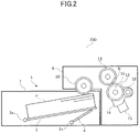
- the sheet feeding portion 230 serving as a sheet feeding apparatus will be described with reference to FIGs. 2 through 5 .
- the sheet feeding portion 230 includes the feed roller 10, the conveyance roller 11 and the retard roller 12.
- the feed roller 10, the conveyance roller 11 and the retard roller 12 are respectively rotatably supported on a sheet feed frame 6 fixed to the apparatus body 150 (refer to FIG. 1 ).
- a swing shaft 18 that supports the retard roller 12 pivotably in up and down directions is attached to the sheet feed frame 6.
- a retard roller holder 14 is attached via the swing shaft 18 to the sheet feed frame 6 in a swingable manner around the swing shaft 18.
- the retard roller holder 14 retains a retard shaft 16 that supports the retard roller 12 rotatably.
- a spring 15 that urges the retard roller holder 14 upward, that is, toward the conveyance roller 11, is arranged below the retard roller holder 14.
- the retard roller holder 14 is arranged pivotably in up and down directions and urged upward, the retard roller 12 is capable of coming into contact with the conveyance roller 11 in a state urged toward the conveyance roller 11. That is, the retard roller 12 is in pressure contact with the conveyance roller 11 by the elastic force of the spring 15. Since the retard roller 12 is in pressure contact with the conveyance roller 11, a separation nip portion N that separates the sheets P is formed between the retard roller 12 and the conveyance roller 11.
- the cassette 1 is capable of being inserted to and removed from the apparatus body 150.
- a support plate 3 capable of supporting sheets P in a stacked manner
- a lifting plate 4 capable of supporting the support plate 3 from below and which is pivotable in up and down directions
- pivot shafts 3a and 4a that respectively pivot the support plate 3 and the lifting plate 4 in up and down directions.
- the support plate 3 is attached to the pivot shaft 3a pivotably around the pivot shaft 3a.
- the lifting plate 4 is arranged below the support plate 3 pivotably around the pivot shaft 4a in up and down directions. The lifting plate 4 pivots by receiving supply of driving force from a lifter motor not shown and lifts the support plate 3.
- the lifting plate 4 pivots in the upper direction around the pivot shaft 4a, by which the support plate 3 is lifted to a position capable of feeding the uppermost sheet P placed on the support plate 3.
- the sheet P is fed by the feed roller 10, and the fed sheet P is separated one by one by the separation nip portion N.
- a drive shaft 17 serving as a drive input shaft is rotatably supported on the sheet feed frame 6 by driving force transmitted from a motor 19 serving as a driving source. Further, the swing shaft 18 is attached to the sheet feed frame 6, as described above.
- the drive shaft 17 and the retard shaft 16 are connected by a joint member 30 serving as a joint that transmits rotary drive force of the drive shaft 17 to the retard shaft 16.
- the drive shaft 17 and the joint member 30 are connected by a first connection portion 25a that does not allow relative rotation of the drive shaft 17 and the joint member 30.
- the joint member 30 and the retard shaft 16 are connected by a second connection portion 25b that does not allow relative rotation of the retard shaft 16 and the joint member 30.
- the retard roller 12 is attached via a torque limiter 13 to an end portion in an axial direction of the retard shaft 16 on a side where the joint member 30 is not connected.
- the torque limiter 13 is interposed between the retard roller 12 and the retard shaft 16.
- the motor 19 rotates only in one direction, and the drive shaft 17, the joint member 30 and the retard shaft 16 rotate only in one direction by driving force of the motor 19.
- the drive shaft 17, the joint member 30 and the retard shaft 16 will be described in further detail with reference to FIG. 4 .
- the drive shaft 17 is formed to rotate in the direction of arrow D2 by being driven by the motor 19 (refer to FIG. 3 ) and to extend in the direction of arrow D3.
- the direction of arrow D3 indicates an axial direction, hereinafter referred to as "drive shaft direction”, of the drive shaft 17.
- the joint member 30 connected to the drive shaft 17 via the first connection portion 25a extends in the direction of arrow D4, and it is formed in a cylindrical shape. That is, arrow D4 indicates an axial direction, hereinafter referred to "joint shaft direction", of the joint member 30.
- the retard shaft 16 connected to the joint member 30 via the second connection portion 25b is formed to extend in a direction of arrow D5. That is, the direction of arrow D5 indicates a retard shaft direction in which the retard shaft 16 extends.
- the retard shaft direction is parallel to the drive shaft direction.
- the first connection portion 25a includes a first pin 20a having a cylindrical shape disposed on the drive shaft 17 and a pair of first groove portions 21a that are formed on the joint member 30 and are engaged with the first pin 20a in response to the rotation of the drive shaft 17.
- the pair of first groove portions 21a is formed at positions having a 180-degree phase difference in the direction of rotation of the joint member 30.
- the first pin 20a serving as a first engaging portion is arranged at an end portion of the drive shaft 17, as illustrated in FIG. 5 , and has a cylindrical shape. Further, the first pin 20a is extended in a direction orthogonal to the drive shaft direction.
- the first pin is not necessarily extended in the direction orthogonal to the drive shaft direction, and it should merely be extended in a direction intersecting the joint shaft direction.
- the first groove portions 21a serving as a first engaged portion are arranged at a first end portion 30b in a joint shaft direction of the joint member 30, and they extend in a joint shaft direction.
- the first pin 20a and the first groove portions 21a are engaged at a first contact portion 22a serving as a first engagement position.
- the second connection portion 25b includes a second pin 20b having a cylindrical shape disposed on the retard shaft 16 and a pair of second groove portions 21b that are formed on the joint member 30 and are engaged with the second pin 20b in response to the rotation of the joint member 30.
- the pair of second groove portions 21b is formed at positions having a 180-degree phase difference in the direction of rotation of the joint member 30.
- the second pin 20b serving as a second engaging portion is arranged at an end portion of the retard shaft 16, as illustrated in FIG. 5 , and has a cylindrical shape. Further, the second pin 20b is extended in a direction orthogonal to the retard shaft direction.
- the second pin 20b is not necessarily extended in a direction orthogonal to the retard shaft direction, and it should merely be extended in a direction intersecting the joint shaft direction.
- the second groove portions 21b serving as a second engaged portion arc arranged at a second end portion 30c in a joint shaft direction of the joint member 30, and they extend in a joint shaft direction.
- the second pin 20b and the second groove portions 21b are engaged at a second contact portion 22b serving as a second engagement position.
- the retard shaft 16 may be deviated with respect to the drive shaft 17 due to influences of dimension accuracy of parts, deformation and wear of rubber roller and so on. That is, as illustrated in FIG. 6 , the joint member 30 may be inclined with respect to the drive shaft 17 and the retard shaft 16, so that the drive shaft direction indicated by arrow D3 and the joint shaft direction indicated by arrow D4 mutually intersect. For example, as illustrated in FIG. 6 , if the retard shaft 16 is deviated toward the downstream side in a sheet conveyance direction, the joint member 30 rotates in an inclined manner with respect to the drive shaft 17 and the retard shaft 16 and transmits driving force from the drive shaft 17 to the retard shaft 16. That is, the retard shaft 16 rotates in an eccentric manner with respect to the drive shaft 17.
- the first groove portions 21a include, as illustrated in FIG. 7 , a first surface 23a and a second surface 24a that extend in the joint shaft direction and are mutually opposed to one another interposing the first pin 20a.
- the first surface 23a is positioned downstream of the second surface 24a in the direction of rotation, i.e., arrow D2 direction, of the joint member 30.
- the second groove portions 21b includes a third surface 23b and a fourth surface 24b that extend in the joint shaft direction and are mutually opposed to one another interposing the second pin 20b.
- the third surface 23b is positioned upstream of the fourth surface 24b in the direction of rotation, i.e., arrow D2 direction, of the joint member 30.
- frictional force generated at the first connection portion 25a and the second connection portion 25b changes periodically according to the phase of the direction of rotation of the first pin 20a and the second pin 20b.
- the frictional force changes depending on the direction in which the shafts of the first pin 20a and the second pin 20b are arranged with respect to the direction in which the retard pressure operates.
- Direction of arrow D6 and direction of arrow D7 illustrated in FIGs. 7 and 8 indicate a swing direction of the retard roller 12.
- the frictional force in the swing direction generated at the first connection portion 25a becomes relatively great in a state where the axial direction of the first pin 20a is arranged in the swing direction of the retard roller 12, as illustrated in FIG. 7 . Therefore, the amount of change of retard pressure becomes great by the frictional force created at the first connection portion 25a. Meanwhile, the frictional force in the swing direction generated at the first connection portion 25a becomes relatively small in a state where the axial direction of the first pin 20a is arranged orthogonal to the swing direction of the retard roller 12, as illustrated in FIG. 8 .
- the amount of change of retard pressure becomes small by the frictional force at the first connection portion 25a.
- Such periodic change of frictional force similarly occurs at the second connection portion 25b, and in response to the rotation of the drive shaft 17, the joint member 30 and the retard shaft 16, the retard pressure periodically changes.
- retard pressure is not stable, the probability of occurrence of conveyance failure such as delay and jamming of sheets or multiple feeding will be increased.
- the retard pressure fluctuates by the influence of frictional force that occurs both at the first connection portion 25a and the second connection portion 25b. Therefore, the final fluctuation of retard pressure appears as a synthetic wave in which a waveform indicating the amount of fluctuation of retard pressured caused by the frictional force at the first connection portion 25a and a waveform indicating the amount of fluctuation of retard pressure caused by the frictional force at the second connection portion 25b are superposed.
- An amplitude of the synthetic wave is determined by a positional relationship of the first pin 20a and the second pin 20b in the direction of rotation of the joint member 30.
- FIG. 9 schematically illustrates the positional relationship of the first pin 20a and the second pin 20b viewed in a second axial direction in which the joint member 30 extends.
- driving force from the motor 19 (refer to FIG. 3 ) is transmitted to the joint member 30 and further transmitted to the retard shaft 16.
- the first pin 20a contacts the downstream side surface of the first groove portions 21a in the direction of arrow D2 between the first surface 23a and the second surface 24a, that is, contacts the first surface 23a at the first contact portion 22a.
- the first contact portion 22a is positioned at a boundary part between the first surface 23a and an outer peripheral surface 30a of the joint member 30.
- the retard roller 12 constantly receives corotating force in the sheet conveyance direction while the driving force is entered from the drive shaft 17. Therefore, the retard shaft 16 is driven by receiving resistance force in a direction resisting against the direction of the driving force being transmitted, that is, resistance force in a direction of arrow D8 that is an opposite direction of rotation as the direction of rotation of the arrow D2. That is, the second pin 20b contacts the downstream side surface of the second groove portions 21b in the direction of arrow D8 between the third surface 23b and the fourth surface 24b, that is, contacts the second contact portion 22b of the third surface 23b.
- the second contact portion 22b is positioned at a boundary part between the third surface 23b and the outer peripheral surface 30a of the joint member 30.
- angle ⁇ can be 0 degrees or greater and smaller than 180 degrees.
- a fluctuation width in which the retard pressure fluctuates that is, the amplitude of the synthetic wave, changes.
- wave C3 which is a synthetic wave of wave C1 indicating the fluctuation of retard pressure generated at the first connection portion 25a and wave C2 indicating the fluctuation of retard pressure generated at the second connection portion 25b, indicates the final fluctuation of retard pressure.
- Wave C3 takes a greater maximum value at time when waves C1 and C2 become maximum and takes a smaller minimum value at time when waves C1 and C2 become minimum.
- the retard pressure indicated by wave C3 has a large deviation quantity from target value F 0 of retard pressure at times when waves C1 and C2 become minimum and maximum.
- the retard roller 12 of the printer 100 (refer to FIG. 1 ) is designed so that the angle ⁇ is approximately 90 degrees.
- waves C1 and C2 are of opposite phase, that is, wave C2 becomes minimum at time when wave C1 becomes maximum, and wave C2 becomes maximum at time when wave C1 becomes minimum.
- wave C3 is a result of wave C1 and wave C2 weakening each other.
- wave C3 becomes minimum when wave C1 becomes maximum and becomes maximum when wave C1 becomes minimum.
- the retard pressure indicated by wave C3 approximates the target value F 0 as a whole, and deviation quantity from the target value F 0 is suppressed to a minimum.
- FIG. 12 is a graph illustrating the relationship between angle ⁇ and fluctuation amplitude of retard pressure.
- the fluctuation amplitude of retard pressure is a periodic function of angle ⁇ where one cycle is 180 degrees.
- angle ⁇ 90° ⁇ 10°.
- the effect of suppressing fluctuation of retard pressure has been described based on angle ⁇ formed by the first straight line LI (refer to FIG. 9 ) and the second straight line L2, but the same concept can be described based on angle ⁇ formed by axis XI and axis X2 illustrated in FIG. 9 .
- the fluctuation amplitude can be suppressed to 5 % or smaller with respect to the minimum value if the angle ⁇ is approximately 60 degrees, that is, if the angle ⁇ is 50 degrees or greater and 70 degrees or smaller, i.e., 50° ⁇ ⁇ ⁇ 70°.
- the angle formed by a center line of the first groove portions 21a and a center line of the first pin 20a in contact with the first contact portion 22a is 15 degrees
- the angle formed by a center line of the second groove portions 21b and a center line of the second pin 20b in contact with the second contact portion 22b is 15 degrees. Therefore, by arranging the first pin 20a and the second pin 20b so that angle ⁇ is approximately 60 degrees in a state where the first pin 20a and the second pin 20b are respectively engaged with the first surface 23a and the third surface 23b, fluctuation of retard pressure can be sufficiently suppressed and conveyance failure of sheets can be reduced. It is effective to approximate angle ⁇ to 60 degrees as much as possible to maximize the effect of suppressing fluctuation of retard pressure.
- the present invention is not limited to the embodiment described above, and it can be implemented in various forms other than the example described above.
- Various components can be omitted, replaced or changed within the scope of the present invention.
- Dimensions, materials, shapes and relative arrangements of components can be varied according to the configuration of the apparatus or various conditions in applying the present invention.
- first pin 20a (refer to FIG. 4 ) is provided on the drive shaft 17 and the first groove portions 21a are formed on the joint member 30, but the present invention is not limited to this example.
- the positional relationship of the first pin 20a and the first groove portions 21a can be opposite. That is, the first pin 20a can be provided on the joint member 30 and the first groove portions 21a can be provided on the drive shaft 17.
- second pin 20b and the second groove portions 21b That is, the second pin 20b can be provided on the joint member 30 and the second groove portions 21b can be provided on the retard shaft 16.
- first pin 20a and the second pin 20b are cylindrical, but the present invention is not limited to this example.
- first pin 20a a rib extending in the axial direction of the drive shaft 17 and capable of engaging with the first groove portions 21a can be provided.
- second pin 20b a rib extending in the axial direction of the retard shaft 16 and capable of engaging with the second groove portions 21b can be provided.
- first groove portions 21a and the second groove portions 21b are groove shaped, but the present invention is not limited to this example.
- the first groove portions 21a and the second groove portions 21b can be a long hole that extends in a second axial direction.
- one of the first groove portions 21a and the second groove portions 21b can be a groove and the other can be a long hole.
- the uppermost sheet P of the sheets P stacked inside the cassette 1 (refer to FIG. 1 ) is fed by the feed roller 10, but the present invention is not limited to this example.
- the conveyance roller 11 can also function as the feed roller 10. That is, the printer 100 can be configured without the feed roller 10 and configured so that the conveyance roller 11 picks up the uppermost sheet P from the sheets P stacked inside the cassette 1 and coveys the sheet P toward the image forming unit 200.
- the printer 100 was described as an example of the image forming apparatus, but the present invention can also be applied to an inkjet type image forming apparatus in which inks are injected through nozzles to form images on sheets.
Landscapes
- Engineering & Computer Science (AREA)
- Mechanical Engineering (AREA)
- General Engineering & Computer Science (AREA)
- Sheets, Magazines, And Separation Thereof (AREA)
- Delivering By Means Of Belts And Rollers (AREA)
Claims (19)
- Eine Blattzuführvorrichtung (230), umfassend:eine Förderwalze (11), die so konfiguriert ist, dass sie Blätter fördert;eine Verzögerungswalze (12), die so konfiguriert ist, dass sie die Förderwalze (11) berührt und die Blätter einzeln trennt;eine Antriebseingangswelle (17), die von einer Antriebsquelle (19) angetrieben ist;eine Verzögerungswelle (16), die so konfiguriert ist, dass sie die Verzögerungswalze (12) drehbar lagert;ein Gelenk (30), das so konfiguriert ist, dass es die Drehantriebskraft der Antriebseingangswelle (17) auf die Verzögerungswelle (16) überträgt;einen ersten Eingriffsabschnitt (20a), der entweder an der Antriebseingangswelle (17) oder dem Gelenk (30) vorgesehen ist;einen ersten Abgriffsabschnitt (21a), der entweder an der Antriebswelle (17) oder dem Gelenk (30) vorgesehen ist und so konfiguriert ist, dass er mit dem ersten Eingriffsabschnitt (20a) in einer ersten Eingriffsposition (22a) in Reaktion auf eine Drehung der Antriebswelle (17) in Eingriff kommt;einen zweiten Eingriffsabschnitt (20b), der entweder an der Verzögerungswelle (16) oder dem Gelenk (30) vorgesehen ist; undeinen zweiten Abgriffsabschnitt (21b), der entweder an der Verzögerungswelle (16) oder dem Gelenk (30) vorgesehen ist und so konfiguriert ist, dass er als Reaktion auf eine Drehung des Gelenks (30) in einer zweiten Eingriffsposition (22b) mit dem zweiten Eingriffsabschnitt (20b) in Eingriff kommt,dadurch gekennzeichnet, dass,in einer axialen Richtung des Gelenks (30) gesehen ein Winkel (θ), der durch eine erste gerade Linie (L1) und eine zweite gerade Linie (L2) gebildet wird, innerhalb eines Bereichs von 80 Grad oder größer und 100 Grad oder kleiner liegt, wobei die erste gerade Linie (L1) durch die erste Eingriffsposition (22a) und einen Drehpunkt der Antriebswelle (17) verläuft, und die zweite gerade Linie (L2) durch die zweite Eingriffsposition (22b) und einen Drehpunkt der Verzögerungswelle (16) verläuft.
- Blattzuführvorrichtung (230) nach Anspruch 1, wobeider erste Eingriffsabschnitt (20a) und der zweite Eingriffsabschnitt (20b) ein erster Stift (20a) bzw. ein zweiter Stift (20b) sind, die sich in einer Richtung erstrecken, die die axiale Richtung des Gelenks (30) schneidet,der erste Abgriffsabschnitt (21a) ein erster Nutabschnitt (21a) ist, der mit dem ersten Stift (20a) in Eingriff ist, undder zweite Abgriffsabschnitt (21b) ein zweiter Nutabschnitt (21b) ist, der mit dem zweiten Stift (20b) in Eingriff steht.
- Blattzuführvorrichtung (230) nach Anspruch 2, wobeider erste Stift (20a) an der Antriebseingangswelle (17) vorgesehen ist,der zweite Stift (20b) auf der Verzögerungswelle (16) vorgesehen ist, undder erste Nutabschnitt (21a) und der zweite Nutabschnitt (21b) jeweils an einem ersten Endabschnitt (30b) und einem zweiten Endabschnitt (30c) in der axialen Richtung des Gelenks (30) vorgesehen sind.
- Blattzuführvorrichtung (230) nach Anspruch 2 oder 3, wobei
sowohl der erste Stift (20a) als auch der zweite Stift (20b) zylindrisch geformt sind. - Blattzuführvorrichtung (230) nach Anspruch 3, wobeider erste Nutabschnitt (21a) eine erste Fläche (23a) und eine zweite Fläche (24a) aufweist, die sich in axialer Richtung des Gelenks (30) erstrecken und die einander gegenüberliegen und den ersten Stift (20a) zwischen sich aufnehmen,der zweite Nutabschnitt (21b) eine dritte Fläche (23b) und eine vierte Fläche (24b) aufweist, die sich in der axialen Richtung des Gelenks (30) erstrecken und die einander gegenüberliegen und den zweiten Stift (20b) zwischen sich aufnehmen,die erste Fläche (23a) in einer Drehrichtung des Gelenks (30) drehrichtungsvorwärts der zweiten Fläche (24a) angeordnet ist und an der ersten Eingriffsposition (22a) mit dem ersten Stift (20a) in Eingriff steht, unddie dritte Fläche (23b) in der Drehrichtung des Gelenks (30) drehrichtungsrückwärts von der vierten Fläche (24b) angeordnet ist und an der zweiten Eingriffsposition (22b) mit dem zweiten Stift (20b) in Eingriff steht.
- Blattzuführvorrichtung (230) nach Anspruch 5, wobeidie erste Eingriffsposition (22a) an einem Grenzbereich zwischen der ersten Fläche (23a) und einer äußeren Umfangsfläche (30a) des Gelenks (30) angeordnet ist, unddie zweite Eingriffsposition (22b) an einem Grenzbereich zwischen der dritten Fläche (23b) und der äußeren Umfangsfläche (30a) des Gelenks (30) angeordnet ist.
- Blattzuführvorrichtung (230) nach Anspruch 5 oder 6, wobei in einem Zustand, in dem der erste Stift (20a) und der zweite Stift (20b) mit der ersten Fläche (23a) bzw. der dritten Fläche (23b) in Eingriff sind, der erste Stift (20a) und der zweite Stift (20b) so angeordnet sind, dass ein Winkel (ϕ), der durch eine Achse (X1) des ersten Stifts (20a) und eine Achse (X2) des zweiten Stifts (20b) gebildet wird, in der axialen Richtung des Gelenks (30) betrachtet innerhalb eines Bereichs von 50 Grad oder größer und 70 Grad oder kleiner liegt.
- Blattzuführvorrichtung (230) nach einem der Ansprüche 1 bis 7, wobeidie Blattzuführvorrichtung (230) ferner einen Drehmomentbegrenzer (13) umfasst, der zwischen der Verzögerungswalze (12) und der Verzögerungswelle (16) angeordnet ist, unddie Antriebseingangswelle (17), das Gelenk (30) und die Verzögerungswelle (16) durch die Antriebskraft der Antriebsquelle (19) nur in einer Richtung gedreht werden.
- Blattzuführvorrichtung (230) nach einem der Ansprüche 1 bis 8, wobei
eine axiale Richtung der Antriebseingangswelle (17) und die axiale Richtung des Gelenks (30) einander schneiden. - Bilderzeugungsgerät (100), mit:der Blattzuführvorrichtung (230) nach einem der Ansprüche 1 bis 9; undeiner Bilderzeugungseinheit (200), die so konfiguriert ist, dass sie ein Bild auf einem von der Blattzuführvorrichtung (230) zugeführten Blatt erzeugt.
- Blattzuführvorrichtung (230), umfassend:eine Förderwalze (11), die so konfiguriert ist, dass sie Blätter fördert;eine Verzögerungswalze (12), die so konfiguriert ist, dass sie die Förderwalze (11) berührt und die Blätter einzeln trennt;eine Antriebseingangswelle (17), die von einer Antriebsquelle (19) angetrieben wird;eine Verzögerungswelle (16), die so konfiguriert ist, dass sie die Verzögerungswalze (12) drehbar lagert;ein Gelenk (30), das so konfiguriert ist, dass es die Drehantriebskraft der Antriebseingangswelle (17) auf die Verzögerungswelle (16) überträgt;einen ersten Stift (20a), der entweder an der Antriebswelle (17) oder an dem Gelenk (30) vorgesehen ist;einen ersten Nutabschnitt (21a), der entweder an der Antriebswelle (17) oder an dem Gelenk (30) vorgesehen ist und so konfiguriert ist, dass er als Reaktion auf eine Drehung der Antriebswelle (17) in einer ersten Eingriffsposition (22a) mit dem ersten Stift (20a) in Eingriff kommt; undeinen zweiten Stift (20b), der entweder an der Verzögerungswelle (16) oder dem Gelenk (30) vorgesehen ist;gekennzeichnet durcheinen zweiten Nutabschnitt (21b), der entweder an der Verzögerungswelle (16) oder an dem Gelenk (30) vorgesehen ist und so konfiguriert ist, dass er als Reaktion auf eine Drehung des Gelenks (30) in einer zweiten Eingriffsposition (22b) mit dem zweiten Stift (20b) in Eingriff kommt,wobei in einem Zustand, in dem der erste Stift (20a) und der zweite Stift (20b) jeweils mit dem ersten Nutabschnitt (21a) und dem zweiten Nutabschnitt (21b) in Eingriff sind, der erste Stift (20a) und der zweite Stift (20b) so angeordnet sind, dass ein Winkel (ϕ), der durch eine Achse (X1) des ersten Stifts (20a) und eine Achse (X2) des zweiten Stifts (20b) gebildet wird, in einer axialen Richtung des Gelenks (30) betrachtet in einem Bereich von 50 Grad oder größer und 70 Grad oder kleiner liegt.
- Blattzuführvorrichtung (230) nach Anspruch 11, wobeiein Winkel (θ), der von einer ersten geraden Linie (L1) und einer zweiten geraden Linie (L2) gebildet wird, in axialer Richtung des Gelenks (30) gesehen 80 Grad oder mehr und 100 Grad oder weniger beträgt,die erste gerade Linie (L1) durch die erste Eingriffsposition (22a) und einen Drehpunkt der Antriebseingangswelle (17) verläuft, unddie zweite gerade Linie (L2) durch die zweite Eingriffsposition (22b) und einen Drehpunkt der Verzögerungswelle (16) verläuft.
- Blattzuführvorrichtung (230) nach Anspruch 11 oder 12, wobeider erste Stift (20a) an der Antriebseingangswelle (17) vorgesehen ist,der zweite Stift (20b) an der Verzögerungswelle (16) vorgesehen ist, undder erste Nutabschnitt (21a) und der zweite Nutabschnitt (21b) jeweils an einem ersten Endabschnitt (30b) und einem zweiten Endabschnitt (30c) in der axialen Richtung des Gelenks (30) vorgesehen sind.
- Blattzuführvorrichtung (230) nach einem der Ansprüche 11 bis 13, wobei
sowohl der erste Stift (20a) als auch der zweite Stift (20b) zylindrisch geformt sind. - Blattzuführvorrichtung (230) nach Anspruch 13, wobeider erste Nutabschnitt (21a) eine erste Fläche (23a) und eine zweite Fläche (24a) aufweist, die sich in der axialen Richtung des Gelenks (30) erstrecken und die einander gegenüberliegen und den ersten Stift (20a) zwischen sich aufnehmen,der zweite Nutabschnitt (21b) eine dritte Fläche (23b) und eine vierte Fläche (24b) aufweist, die sich in der axialen Richtung des Gelenks (30) erstrecken und die einander gegenüberliegen und den zweiten Stift (20b) zwischen sich aufnehmen,die erste Fläche (23a) in einer Drehrichtung des Gelenks (30) drehrichtungsvorwärts der zweiten Fläche (24a) angeordnet ist und an der ersten Eingriffsposition (22a) mit dem ersten Stift (20a) in Eingriff steht, unddie dritte Fläche (23b) in der Drehrichtung des Gelenks (30) drehrichtungsrückwärts von der vierten Fläche (24b) angeordnet ist und an der zweiten Eingriffsposition (22b) mit dem zweiten Stift (20b) in Eingriff steht.
- Blattzuführvorrichtung (230) nach Anspruch 15, wobeidie erste Eingriffsposition (22a) an einem Grenzbereich zwischen der ersten Fläche (23a) und einer äußeren Umfangsfläche (30a) des Gelenks (30) angeordnet ist, unddie zweite Eingriffsposition (22b) an einem Grenzbereich zwischen der dritten Fläche (23b) und der äußeren Umfangsfläche (30a) des Gelenks (30) angeordnet ist.
- Blattzuführvorrichtung (230) nach einem der Ansprüche 11 bis 16, wobeidie Blattzuführvorrichtung (230) ferner einen Drehmomentbegrenzer (13) umfasst, der zwischen der Verzögerungswalze (12) und der Verzögerungswelle (16) angeordnet ist, unddie Antriebseingangswelle (17), das Gelenk (30) und die Verzögerungswelle (16) durch die Antriebskraft der Antriebsquelle (19) nur in einer Richtung gedreht werden.
- Blattzuführvorrichtung (230) nach einem der Ansprüche 11 bis 17, wobei
eine axiale Richtung der Antriebseingangswelle (17) und die axiale Richtung des Gelenks (30) einander schneiden. - Bilderzeugungsgerät (100) mit:der Blattzuführvorrichtung (230) nach einem der Ansprüche 11 bis 18; undeiner Bilderzeugungseinheit (200), die zum Erzeugen eines Bildes auf einem von der Blattzuführvorrichtung (230) zugeführten Blatt konfiguriert ist.
Applications Claiming Priority (1)
| Application Number | Priority Date | Filing Date | Title |
|---|---|---|---|
| JP2018108092A JP7071221B2 (ja) | 2018-06-05 | 2018-06-05 | シート給送装置及び画像形成装置 |
Publications (2)
| Publication Number | Publication Date |
|---|---|
| EP3578486A1 EP3578486A1 (de) | 2019-12-11 |
| EP3578486B1 true EP3578486B1 (de) | 2022-04-06 |
Family
ID=66597510
Family Applications (1)
| Application Number | Title | Priority Date | Filing Date |
|---|---|---|---|
| EP19174814.4A Active EP3578486B1 (de) | 2018-06-05 | 2019-05-16 | Blattzuführvorrichtung und bilderzeugungsvorrichtung |
Country Status (4)
| Country | Link |
|---|---|
| US (1) | US11180331B2 (de) |
| EP (1) | EP3578486B1 (de) |
| JP (1) | JP7071221B2 (de) |
| CN (1) | CN110562774B (de) |
Families Citing this family (5)
| Publication number | Priority date | Publication date | Assignee | Title |
|---|---|---|---|---|
| US11905137B2 (en) | 2020-09-03 | 2024-02-20 | Canon Kabushiki Kaisha | Sheet feeding device and image forming apparatus |
| JP2022110457A (ja) | 2021-01-18 | 2022-07-29 | キヤノン株式会社 | シート搬送装置及び画像形成装置 |
| JP2023158486A (ja) * | 2022-04-18 | 2023-10-30 | キヤノン株式会社 | 軸及び画像形成装置 |
| JP7763570B2 (ja) * | 2023-04-14 | 2025-11-04 | ヒラノ技研工業株式会社 | 回転体の支持装置 |
| JP2024160496A (ja) * | 2023-05-01 | 2024-11-14 | ブラザー工業株式会社 | 画像形成装置 |
Family Cites Families (12)
| Publication number | Priority date | Publication date | Assignee | Title |
|---|---|---|---|---|
| US5040779A (en) * | 1988-06-23 | 1991-08-20 | Mita Industrial Co., Ltd. | Detachable paper delivery roller for a paper utilizing device |
| US5501542A (en) * | 1994-09-23 | 1996-03-26 | Farmatic Research, Inc. | Rapid coupling for a supported, driven shaft |
| JP3880084B2 (ja) | 1995-09-29 | 2007-02-14 | キヤノン株式会社 | シート送り装置及び画像読取装置 |
| JP3715717B2 (ja) * | 1996-07-10 | 2005-11-16 | キヤノン株式会社 | 駆動伝達装置及びシート材給送装置 |
| US6206368B1 (en) * | 1998-03-17 | 2001-03-27 | Kyocera Mita Corporation | Paper transport device with one roller pair |
| JP2001097587A (ja) * | 1999-10-01 | 2001-04-10 | Canon Inc | シート搬送分離装置とこの装置を備えた画像読取装置及び画像形成装置 |
| JP4046933B2 (ja) * | 2000-08-02 | 2008-02-13 | キヤノン株式会社 | 駆動伝達装置及びこれを備える画像形成装置 |
| JP5220284B2 (ja) | 2006-05-15 | 2013-06-26 | 株式会社ハーモニック・ドライブ・システムズ | フィルム巻き取りロールの回転機構 |
| JP2012008504A (ja) | 2010-06-28 | 2012-01-12 | Fuji Xerox Co Ltd | 画像形成装置 |
| CN203187142U (zh) | 2013-04-10 | 2013-09-11 | 珠海赛纳打印科技股份有限公司 | 自动馈纸装置和成像装置 |
| CN104249943B (zh) | 2013-06-26 | 2016-09-21 | 东友科技股份有限公司 | 具有旋转元件的挡纸机构及其所适用的自动馈纸装置 |
| CN103738750B (zh) | 2013-12-17 | 2016-04-20 | 安徽华印机电股份有限公司 | 搭页机用分帖装置 |
-
2018
- 2018-06-05 JP JP2018108092A patent/JP7071221B2/ja active Active
-
2019
- 2019-05-16 EP EP19174814.4A patent/EP3578486B1/de active Active
- 2019-05-17 US US16/414,930 patent/US11180331B2/en active Active
- 2019-05-31 CN CN201910465784.8A patent/CN110562774B/zh active Active
Also Published As
| Publication number | Publication date |
|---|---|
| US11180331B2 (en) | 2021-11-23 |
| JP2019210104A (ja) | 2019-12-12 |
| CN110562774A (zh) | 2019-12-13 |
| CN110562774B (zh) | 2021-07-27 |
| EP3578486A1 (de) | 2019-12-11 |
| JP7071221B2 (ja) | 2022-05-18 |
| US20190367302A1 (en) | 2019-12-05 |
Similar Documents
| Publication | Publication Date | Title |
|---|---|---|
| EP3578486B1 (de) | Blattzuführvorrichtung und bilderzeugungsvorrichtung | |
| EP2845824B1 (de) | Blattfördervorrichtung und Bilderzeugungsvorrichtung damit | |
| US9908727B2 (en) | Sheet conveyance apparatus and image forming apparatus | |
| US8761657B2 (en) | Image forming apparatus | |
| USRE42572E1 (en) | Belt device | |
| US20130221612A1 (en) | Image forming apparatus | |
| US10852684B2 (en) | Drive transmission apparatus and image forming apparatus | |
| US11966183B2 (en) | Sheet conveyance apparatus and image forming apparatus | |
| US11480896B2 (en) | Belt conveyance apparatus and image forming apparatus | |
| US20190039848A1 (en) | Sheet stacking apparatus and image forming apparatus | |
| US10543996B2 (en) | Sheet feeding apparatus and image forming apparatus | |
| CN120704083A (zh) | 图像形成设备 | |
| US11479425B2 (en) | One-way clutch, sheet conveying apparatus, and image forming apparatus | |
| JP5165077B2 (ja) | 二次転写ユニットの変位機構及び画像形成装置 | |
| US10221030B2 (en) | Sheet conveying apparatus and image forming apparatus | |
| JP4378132B2 (ja) | 画像形成装置 | |
| JP7207850B2 (ja) | シート給送装置及び画像形成装置 | |
| JP6750874B2 (ja) | シート給送装置及び画像形成装置 | |
| US12466674B2 (en) | Shaft and image forming apparatus | |
| US11934115B2 (en) | Transport device | |
| US20170355546A1 (en) | Sheet conveyance device and image forming apparatus | |
| JP7497256B2 (ja) | シート搬送装置及び画像形成装置 | |
| US10534307B2 (en) | Image forming apparatus | |
| JP2007309954A (ja) | 回転カム機構及びこれを備える画像形成装置 | |
| JP2009271380A (ja) | 駆動伝達手段、画像形成装置 |
Legal Events
| Date | Code | Title | Description |
|---|---|---|---|
| PUAI | Public reference made under article 153(3) epc to a published international application that has entered the european phase |
Free format text: ORIGINAL CODE: 0009012 |
|
| STAA | Information on the status of an ep patent application or granted ep patent |
Free format text: STATUS: THE APPLICATION HAS BEEN PUBLISHED |
|
| AK | Designated contracting states |
Kind code of ref document: A1 Designated state(s): AL AT BE BG CH CY CZ DE DK EE ES FI FR GB GR HR HU IE IS IT LI LT LU LV MC MK MT NL NO PL PT RO RS SE SI SK SM TR |
|
| AX | Request for extension of the european patent |
Extension state: BA ME |
|
| STAA | Information on the status of an ep patent application or granted ep patent |
Free format text: STATUS: REQUEST FOR EXAMINATION WAS MADE |
|
| 17P | Request for examination filed |
Effective date: 20200612 |
|
| RBV | Designated contracting states (corrected) |
Designated state(s): AL AT BE BG CH CY CZ DE DK EE ES FI FR GB GR HR HU IE IS IT LI LT LU LV MC MK MT NL NO PL PT RO RS SE SI SK SM TR |
|
| GRAP | Despatch of communication of intention to grant a patent |
Free format text: ORIGINAL CODE: EPIDOSNIGR1 |
|
| STAA | Information on the status of an ep patent application or granted ep patent |
Free format text: STATUS: GRANT OF PATENT IS INTENDED |
|
| INTG | Intention to grant announced |
Effective date: 20211027 |
|
| GRAS | Grant fee paid |
Free format text: ORIGINAL CODE: EPIDOSNIGR3 |
|
| GRAA | (expected) grant |
Free format text: ORIGINAL CODE: 0009210 |
|
| STAA | Information on the status of an ep patent application or granted ep patent |
Free format text: STATUS: THE PATENT HAS BEEN GRANTED |
|
| AK | Designated contracting states |
Kind code of ref document: B1 Designated state(s): AL AT BE BG CH CY CZ DE DK EE ES FI FR GB GR HR HU IE IS IT LI LT LU LV MC MK MT NL NO PL PT RO RS SE SI SK SM TR |
|
| REG | Reference to a national code |
Ref country code: GB Ref legal event code: FG4D |
|
| REG | Reference to a national code |
Ref country code: CH Ref legal event code: EP |
|
| REG | Reference to a national code |
Ref country code: AT Ref legal event code: REF Ref document number: 1481173 Country of ref document: AT Kind code of ref document: T Effective date: 20220415 |
|
| REG | Reference to a national code |
Ref country code: IE Ref legal event code: FG4D |
|
| REG | Reference to a national code |
Ref country code: DE Ref legal event code: R096 Ref document number: 602019013271 Country of ref document: DE |
|
| REG | Reference to a national code |
Ref country code: LT Ref legal event code: MG9D |
|
| REG | Reference to a national code |
Ref country code: NL Ref legal event code: MP Effective date: 20220406 |
|
| REG | Reference to a national code |
Ref country code: AT Ref legal event code: MK05 Ref document number: 1481173 Country of ref document: AT Kind code of ref document: T Effective date: 20220406 |
|
| PG25 | Lapsed in a contracting state [announced via postgrant information from national office to epo] |
Ref country code: NL Free format text: LAPSE BECAUSE OF FAILURE TO SUBMIT A TRANSLATION OF THE DESCRIPTION OR TO PAY THE FEE WITHIN THE PRESCRIBED TIME-LIMIT Effective date: 20220406 |
|
| PG25 | Lapsed in a contracting state [announced via postgrant information from national office to epo] |
Ref country code: SE Free format text: LAPSE BECAUSE OF FAILURE TO SUBMIT A TRANSLATION OF THE DESCRIPTION OR TO PAY THE FEE WITHIN THE PRESCRIBED TIME-LIMIT Effective date: 20220406 Ref country code: PT Free format text: LAPSE BECAUSE OF FAILURE TO SUBMIT A TRANSLATION OF THE DESCRIPTION OR TO PAY THE FEE WITHIN THE PRESCRIBED TIME-LIMIT Effective date: 20220808 Ref country code: NO Free format text: LAPSE BECAUSE OF FAILURE TO SUBMIT A TRANSLATION OF THE DESCRIPTION OR TO PAY THE FEE WITHIN THE PRESCRIBED TIME-LIMIT Effective date: 20220706 Ref country code: LT Free format text: LAPSE BECAUSE OF FAILURE TO SUBMIT A TRANSLATION OF THE DESCRIPTION OR TO PAY THE FEE WITHIN THE PRESCRIBED TIME-LIMIT Effective date: 20220406 Ref country code: HR Free format text: LAPSE BECAUSE OF FAILURE TO SUBMIT A TRANSLATION OF THE DESCRIPTION OR TO PAY THE FEE WITHIN THE PRESCRIBED TIME-LIMIT Effective date: 20220406 Ref country code: GR Free format text: LAPSE BECAUSE OF FAILURE TO SUBMIT A TRANSLATION OF THE DESCRIPTION OR TO PAY THE FEE WITHIN THE PRESCRIBED TIME-LIMIT Effective date: 20220707 Ref country code: FI Free format text: LAPSE BECAUSE OF FAILURE TO SUBMIT A TRANSLATION OF THE DESCRIPTION OR TO PAY THE FEE WITHIN THE PRESCRIBED TIME-LIMIT Effective date: 20220406 Ref country code: ES Free format text: LAPSE BECAUSE OF FAILURE TO SUBMIT A TRANSLATION OF THE DESCRIPTION OR TO PAY THE FEE WITHIN THE PRESCRIBED TIME-LIMIT Effective date: 20220406 Ref country code: BG Free format text: LAPSE BECAUSE OF FAILURE TO SUBMIT A TRANSLATION OF THE DESCRIPTION OR TO PAY THE FEE WITHIN THE PRESCRIBED TIME-LIMIT Effective date: 20220706 Ref country code: AT Free format text: LAPSE BECAUSE OF FAILURE TO SUBMIT A TRANSLATION OF THE DESCRIPTION OR TO PAY THE FEE WITHIN THE PRESCRIBED TIME-LIMIT Effective date: 20220406 |
|
| PG25 | Lapsed in a contracting state [announced via postgrant information from national office to epo] |
Ref country code: RS Free format text: LAPSE BECAUSE OF FAILURE TO SUBMIT A TRANSLATION OF THE DESCRIPTION OR TO PAY THE FEE WITHIN THE PRESCRIBED TIME-LIMIT Effective date: 20220406 Ref country code: PL Free format text: LAPSE BECAUSE OF FAILURE TO SUBMIT A TRANSLATION OF THE DESCRIPTION OR TO PAY THE FEE WITHIN THE PRESCRIBED TIME-LIMIT Effective date: 20220406 Ref country code: LV Free format text: LAPSE BECAUSE OF FAILURE TO SUBMIT A TRANSLATION OF THE DESCRIPTION OR TO PAY THE FEE WITHIN THE PRESCRIBED TIME-LIMIT Effective date: 20220406 Ref country code: IS Free format text: LAPSE BECAUSE OF FAILURE TO SUBMIT A TRANSLATION OF THE DESCRIPTION OR TO PAY THE FEE WITHIN THE PRESCRIBED TIME-LIMIT Effective date: 20220806 |
|
| REG | Reference to a national code |
Ref country code: DE Ref legal event code: R119 Ref document number: 602019013271 Country of ref document: DE |
|
| REG | Reference to a national code |
Ref country code: CH Ref legal event code: PL |
|
| REG | Reference to a national code |
Ref country code: BE Ref legal event code: MM Effective date: 20220531 |
|
| PG25 | Lapsed in a contracting state [announced via postgrant information from national office to epo] |
Ref country code: SM Free format text: LAPSE BECAUSE OF FAILURE TO SUBMIT A TRANSLATION OF THE DESCRIPTION OR TO PAY THE FEE WITHIN THE PRESCRIBED TIME-LIMIT Effective date: 20220406 Ref country code: SK Free format text: LAPSE BECAUSE OF FAILURE TO SUBMIT A TRANSLATION OF THE DESCRIPTION OR TO PAY THE FEE WITHIN THE PRESCRIBED TIME-LIMIT Effective date: 20220406 Ref country code: RO Free format text: LAPSE BECAUSE OF FAILURE TO SUBMIT A TRANSLATION OF THE DESCRIPTION OR TO PAY THE FEE WITHIN THE PRESCRIBED TIME-LIMIT Effective date: 20220406 Ref country code: MC Free format text: LAPSE BECAUSE OF FAILURE TO SUBMIT A TRANSLATION OF THE DESCRIPTION OR TO PAY THE FEE WITHIN THE PRESCRIBED TIME-LIMIT Effective date: 20220406 Ref country code: LU Free format text: LAPSE BECAUSE OF NON-PAYMENT OF DUE FEES Effective date: 20220516 Ref country code: LI Free format text: LAPSE BECAUSE OF NON-PAYMENT OF DUE FEES Effective date: 20220531 Ref country code: EE Free format text: LAPSE BECAUSE OF FAILURE TO SUBMIT A TRANSLATION OF THE DESCRIPTION OR TO PAY THE FEE WITHIN THE PRESCRIBED TIME-LIMIT Effective date: 20220406 Ref country code: DK Free format text: LAPSE BECAUSE OF FAILURE TO SUBMIT A TRANSLATION OF THE DESCRIPTION OR TO PAY THE FEE WITHIN THE PRESCRIBED TIME-LIMIT Effective date: 20220406 Ref country code: CZ Free format text: LAPSE BECAUSE OF FAILURE TO SUBMIT A TRANSLATION OF THE DESCRIPTION OR TO PAY THE FEE WITHIN THE PRESCRIBED TIME-LIMIT Effective date: 20220406 Ref country code: CH Free format text: LAPSE BECAUSE OF NON-PAYMENT OF DUE FEES Effective date: 20220531 |
|
| PLBE | No opposition filed within time limit |
Free format text: ORIGINAL CODE: 0009261 |
|
| STAA | Information on the status of an ep patent application or granted ep patent |
Free format text: STATUS: NO OPPOSITION FILED WITHIN TIME LIMIT |
|
| 26N | No opposition filed |
Effective date: 20230110 |
|
| PG25 | Lapsed in a contracting state [announced via postgrant information from national office to epo] |
Ref country code: AL Free format text: LAPSE BECAUSE OF FAILURE TO SUBMIT A TRANSLATION OF THE DESCRIPTION OR TO PAY THE FEE WITHIN THE PRESCRIBED TIME-LIMIT Effective date: 20220406 |
|
| PG25 | Lapsed in a contracting state [announced via postgrant information from national office to epo] |
Ref country code: IE Free format text: LAPSE BECAUSE OF NON-PAYMENT OF DUE FEES Effective date: 20220516 Ref country code: FR Free format text: LAPSE BECAUSE OF NON-PAYMENT OF DUE FEES Effective date: 20220606 |
|
| PG25 | Lapsed in a contracting state [announced via postgrant information from national office to epo] |
Ref country code: SI Free format text: LAPSE BECAUSE OF FAILURE TO SUBMIT A TRANSLATION OF THE DESCRIPTION OR TO PAY THE FEE WITHIN THE PRESCRIBED TIME-LIMIT Effective date: 20220406 Ref country code: DE Free format text: LAPSE BECAUSE OF NON-PAYMENT OF DUE FEES Effective date: 20221201 Ref country code: BE Free format text: LAPSE BECAUSE OF NON-PAYMENT OF DUE FEES Effective date: 20220531 |
|
| PG25 | Lapsed in a contracting state [announced via postgrant information from national office to epo] |
Ref country code: IT Free format text: LAPSE BECAUSE OF FAILURE TO SUBMIT A TRANSLATION OF THE DESCRIPTION OR TO PAY THE FEE WITHIN THE PRESCRIBED TIME-LIMIT Effective date: 20220406 |
|
| PG25 | Lapsed in a contracting state [announced via postgrant information from national office to epo] |
Ref country code: MK Free format text: LAPSE BECAUSE OF FAILURE TO SUBMIT A TRANSLATION OF THE DESCRIPTION OR TO PAY THE FEE WITHIN THE PRESCRIBED TIME-LIMIT Effective date: 20220406 Ref country code: CY Free format text: LAPSE BECAUSE OF FAILURE TO SUBMIT A TRANSLATION OF THE DESCRIPTION OR TO PAY THE FEE WITHIN THE PRESCRIBED TIME-LIMIT Effective date: 20220406 |
|
| PG25 | Lapsed in a contracting state [announced via postgrant information from national office to epo] |
Ref country code: HU Free format text: LAPSE BECAUSE OF FAILURE TO SUBMIT A TRANSLATION OF THE DESCRIPTION OR TO PAY THE FEE WITHIN THE PRESCRIBED TIME-LIMIT; INVALID AB INITIO Effective date: 20190516 |
|
| PG25 | Lapsed in a contracting state [announced via postgrant information from national office to epo] |
Ref country code: MT Free format text: LAPSE BECAUSE OF FAILURE TO SUBMIT A TRANSLATION OF THE DESCRIPTION OR TO PAY THE FEE WITHIN THE PRESCRIBED TIME-LIMIT Effective date: 20220406 |
|
| PG25 | Lapsed in a contracting state [announced via postgrant information from national office to epo] |
Ref country code: BG Free format text: LAPSE BECAUSE OF FAILURE TO SUBMIT A TRANSLATION OF THE DESCRIPTION OR TO PAY THE FEE WITHIN THE PRESCRIBED TIME-LIMIT Effective date: 20220406 |
|
| PG25 | Lapsed in a contracting state [announced via postgrant information from national office to epo] |
Ref country code: BG Free format text: LAPSE BECAUSE OF FAILURE TO SUBMIT A TRANSLATION OF THE DESCRIPTION OR TO PAY THE FEE WITHIN THE PRESCRIBED TIME-LIMIT Effective date: 20220406 |
|
| PGFP | Annual fee paid to national office [announced via postgrant information from national office to epo] |
Ref country code: GB Payment date: 20250423 Year of fee payment: 7 |
|
| PG25 | Lapsed in a contracting state [announced via postgrant information from national office to epo] |
Ref country code: TR Free format text: LAPSE BECAUSE OF FAILURE TO SUBMIT A TRANSLATION OF THE DESCRIPTION OR TO PAY THE FEE WITHIN THE PRESCRIBED TIME-LIMIT Effective date: 20220406 |