EP3576232A2 - Laservorrichtung - Google Patents
Laservorrichtung Download PDFInfo
- Publication number
- EP3576232A2 EP3576232A2 EP19176946.2A EP19176946A EP3576232A2 EP 3576232 A2 EP3576232 A2 EP 3576232A2 EP 19176946 A EP19176946 A EP 19176946A EP 3576232 A2 EP3576232 A2 EP 3576232A2
- Authority
- EP
- European Patent Office
- Prior art keywords
- laser medium
- seed light
- mirror
- laser
- medium
- Prior art date
- Legal status (The legal status is an assumption and is not a legal conclusion. Google has not performed a legal analysis and makes no representation as to the accuracy of the status listed.)
- Granted
Links
Images


Classifications
-
- H—ELECTRICITY
- H01—ELECTRIC ELEMENTS
- H01S—DEVICES USING THE PROCESS OF LIGHT AMPLIFICATION BY STIMULATED EMISSION OF RADIATION [LASER] TO AMPLIFY OR GENERATE LIGHT; DEVICES USING STIMULATED EMISSION OF ELECTROMAGNETIC RADIATION IN WAVE RANGES OTHER THAN OPTICAL
- H01S3/00—Lasers, i.e. devices using stimulated emission of electromagnetic radiation in the infrared, visible or ultraviolet wave range
- H01S3/02—Constructional details
- H01S3/04—Arrangements for thermal management
- H01S3/0404—Air- or gas cooling, e.g. by dry nitrogen
-
- H—ELECTRICITY
- H01—ELECTRIC ELEMENTS
- H01S—DEVICES USING THE PROCESS OF LIGHT AMPLIFICATION BY STIMULATED EMISSION OF RADIATION [LASER] TO AMPLIFY OR GENERATE LIGHT; DEVICES USING STIMULATED EMISSION OF ELECTROMAGNETIC RADIATION IN WAVE RANGES OTHER THAN OPTICAL
- H01S3/00—Lasers, i.e. devices using stimulated emission of electromagnetic radiation in the infrared, visible or ultraviolet wave range
- H01S3/02—Constructional details
- H01S3/04—Arrangements for thermal management
- H01S3/0407—Liquid cooling, e.g. by water
-
- H—ELECTRICITY
- H01—ELECTRIC ELEMENTS
- H01S—DEVICES USING THE PROCESS OF LIGHT AMPLIFICATION BY STIMULATED EMISSION OF RADIATION [LASER] TO AMPLIFY OR GENERATE LIGHT; DEVICES USING STIMULATED EMISSION OF ELECTROMAGNETIC RADIATION IN WAVE RANGES OTHER THAN OPTICAL
- H01S3/00—Lasers, i.e. devices using stimulated emission of electromagnetic radiation in the infrared, visible or ultraviolet wave range
- H01S3/02—Constructional details
- H01S3/025—Constructional details of solid state lasers, e.g. housings or mountings
-
- H—ELECTRICITY
- H01—ELECTRIC ELEMENTS
- H01S—DEVICES USING THE PROCESS OF LIGHT AMPLIFICATION BY STIMULATED EMISSION OF RADIATION [LASER] TO AMPLIFY OR GENERATE LIGHT; DEVICES USING STIMULATED EMISSION OF ELECTROMAGNETIC RADIATION IN WAVE RANGES OTHER THAN OPTICAL
- H01S3/00—Lasers, i.e. devices using stimulated emission of electromagnetic radiation in the infrared, visible or ultraviolet wave range
- H01S3/02—Constructional details
- H01S3/04—Arrangements for thermal management
- H01S3/0405—Conductive cooling, e.g. by heat sinks or thermo-electric elements
-
- H—ELECTRICITY
- H01—ELECTRIC ELEMENTS
- H01S—DEVICES USING THE PROCESS OF LIGHT AMPLIFICATION BY STIMULATED EMISSION OF RADIATION [LASER] TO AMPLIFY OR GENERATE LIGHT; DEVICES USING STIMULATED EMISSION OF ELECTROMAGNETIC RADIATION IN WAVE RANGES OTHER THAN OPTICAL
- H01S3/00—Lasers, i.e. devices using stimulated emission of electromagnetic radiation in the infrared, visible or ultraviolet wave range
- H01S3/02—Constructional details
- H01S3/04—Arrangements for thermal management
- H01S3/042—Arrangements for thermal management for solid state lasers
-
- H—ELECTRICITY
- H01—ELECTRIC ELEMENTS
- H01S—DEVICES USING THE PROCESS OF LIGHT AMPLIFICATION BY STIMULATED EMISSION OF RADIATION [LASER] TO AMPLIFY OR GENERATE LIGHT; DEVICES USING STIMULATED EMISSION OF ELECTROMAGNETIC RADIATION IN WAVE RANGES OTHER THAN OPTICAL
- H01S3/00—Lasers, i.e. devices using stimulated emission of electromagnetic radiation in the infrared, visible or ultraviolet wave range
- H01S3/05—Construction or shape of optical resonators; Accommodation of active medium therein; Shape of active medium
- H01S3/06—Construction or shape of active medium
- H01S3/07—Construction or shape of active medium consisting of a plurality of parts, e.g. segments
-
- H—ELECTRICITY
- H01—ELECTRIC ELEMENTS
- H01S—DEVICES USING THE PROCESS OF LIGHT AMPLIFICATION BY STIMULATED EMISSION OF RADIATION [LASER] TO AMPLIFY OR GENERATE LIGHT; DEVICES USING STIMULATED EMISSION OF ELECTROMAGNETIC RADIATION IN WAVE RANGES OTHER THAN OPTICAL
- H01S3/00—Lasers, i.e. devices using stimulated emission of electromagnetic radiation in the infrared, visible or ultraviolet wave range
- H01S3/05—Construction or shape of optical resonators; Accommodation of active medium therein; Shape of active medium
- H01S3/08—Construction or shape of optical resonators or components thereof
- H01S3/08059—Constructional details of the reflector, e.g. shape
-
- H—ELECTRICITY
- H01—ELECTRIC ELEMENTS
- H01S—DEVICES USING THE PROCESS OF LIGHT AMPLIFICATION BY STIMULATED EMISSION OF RADIATION [LASER] TO AMPLIFY OR GENERATE LIGHT; DEVICES USING STIMULATED EMISSION OF ELECTROMAGNETIC RADIATION IN WAVE RANGES OTHER THAN OPTICAL
- H01S3/00—Lasers, i.e. devices using stimulated emission of electromagnetic radiation in the infrared, visible or ultraviolet wave range
- H01S3/10—Controlling the intensity, frequency, phase, polarisation or direction of the emitted radiation, e.g. switching, gating, modulating or demodulating
- H01S3/10007—Controlling the intensity, frequency, phase, polarisation or direction of the emitted radiation, e.g. switching, gating, modulating or demodulating in optical amplifiers
-
- H—ELECTRICITY
- H01—ELECTRIC ELEMENTS
- H01S—DEVICES USING THE PROCESS OF LIGHT AMPLIFICATION BY STIMULATED EMISSION OF RADIATION [LASER] TO AMPLIFY OR GENERATE LIGHT; DEVICES USING STIMULATED EMISSION OF ELECTROMAGNETIC RADIATION IN WAVE RANGES OTHER THAN OPTICAL
- H01S3/00—Lasers, i.e. devices using stimulated emission of electromagnetic radiation in the infrared, visible or ultraviolet wave range
- H01S3/10—Controlling the intensity, frequency, phase, polarisation or direction of the emitted radiation, e.g. switching, gating, modulating or demodulating
- H01S3/10084—Frequency control by seeding
- H01S3/10092—Coherent seed, e.g. injection locking
-
- H—ELECTRICITY
- H01—ELECTRIC ELEMENTS
- H01S—DEVICES USING THE PROCESS OF LIGHT AMPLIFICATION BY STIMULATED EMISSION OF RADIATION [LASER] TO AMPLIFY OR GENERATE LIGHT; DEVICES USING STIMULATED EMISSION OF ELECTROMAGNETIC RADIATION IN WAVE RANGES OTHER THAN OPTICAL
- H01S3/00—Lasers, i.e. devices using stimulated emission of electromagnetic radiation in the infrared, visible or ultraviolet wave range
- H01S3/23—Arrangements of two or more lasers not provided for in groups H01S3/02 - H01S3/22, e.g. tandem arrangements of separate active media
- H01S3/2308—Amplifier arrangements, e.g. MOPA
- H01S3/2316—Cascaded amplifiers
-
- H—ELECTRICITY
- H01—ELECTRIC ELEMENTS
- H01S—DEVICES USING THE PROCESS OF LIGHT AMPLIFICATION BY STIMULATED EMISSION OF RADIATION [LASER] TO AMPLIFY OR GENERATE LIGHT; DEVICES USING STIMULATED EMISSION OF ELECTROMAGNETIC RADIATION IN WAVE RANGES OTHER THAN OPTICAL
- H01S2301/00—Functional characteristics
- H01S2301/02—ASE (amplified spontaneous emission), noise; Reduction thereof
-
- H—ELECTRICITY
- H01—ELECTRIC ELEMENTS
- H01S—DEVICES USING THE PROCESS OF LIGHT AMPLIFICATION BY STIMULATED EMISSION OF RADIATION [LASER] TO AMPLIFY OR GENERATE LIGHT; DEVICES USING STIMULATED EMISSION OF ELECTROMAGNETIC RADIATION IN WAVE RANGES OTHER THAN OPTICAL
- H01S3/00—Lasers, i.e. devices using stimulated emission of electromagnetic radiation in the infrared, visible or ultraviolet wave range
- H01S3/05—Construction or shape of optical resonators; Accommodation of active medium therein; Shape of active medium
- H01S3/06—Construction or shape of active medium
- H01S3/0602—Crystal lasers or glass lasers
- H01S3/0604—Crystal lasers or glass lasers in the form of a plate or disc
-
- H—ELECTRICITY
- H01—ELECTRIC ELEMENTS
- H01S—DEVICES USING THE PROCESS OF LIGHT AMPLIFICATION BY STIMULATED EMISSION OF RADIATION [LASER] TO AMPLIFY OR GENERATE LIGHT; DEVICES USING STIMULATED EMISSION OF ELECTROMAGNETIC RADIATION IN WAVE RANGES OTHER THAN OPTICAL
- H01S3/00—Lasers, i.e. devices using stimulated emission of electromagnetic radiation in the infrared, visible or ultraviolet wave range
- H01S3/05—Construction or shape of optical resonators; Accommodation of active medium therein; Shape of active medium
- H01S3/06—Construction or shape of active medium
- H01S3/0619—Coatings, e.g. AR, HR, passivation layer
- H01S3/0621—Coatings on the end-faces, e.g. input/output surfaces of the laser light
-
- H—ELECTRICITY
- H01—ELECTRIC ELEMENTS
- H01S—DEVICES USING THE PROCESS OF LIGHT AMPLIFICATION BY STIMULATED EMISSION OF RADIATION [LASER] TO AMPLIFY OR GENERATE LIGHT; DEVICES USING STIMULATED EMISSION OF ELECTROMAGNETIC RADIATION IN WAVE RANGES OTHER THAN OPTICAL
- H01S3/00—Lasers, i.e. devices using stimulated emission of electromagnetic radiation in the infrared, visible or ultraviolet wave range
- H01S3/14—Lasers, i.e. devices using stimulated emission of electromagnetic radiation in the infrared, visible or ultraviolet wave range characterised by the material used as the active medium
- H01S3/16—Solid materials
- H01S3/1601—Solid materials characterised by an active (lasing) ion
- H01S3/1603—Solid materials characterised by an active (lasing) ion rare earth
- H01S3/1618—Solid materials characterised by an active (lasing) ion rare earth ytterbium
-
- H—ELECTRICITY
- H01—ELECTRIC ELEMENTS
- H01S—DEVICES USING THE PROCESS OF LIGHT AMPLIFICATION BY STIMULATED EMISSION OF RADIATION [LASER] TO AMPLIFY OR GENERATE LIGHT; DEVICES USING STIMULATED EMISSION OF ELECTROMAGNETIC RADIATION IN WAVE RANGES OTHER THAN OPTICAL
- H01S3/00—Lasers, i.e. devices using stimulated emission of electromagnetic radiation in the infrared, visible or ultraviolet wave range
- H01S3/14—Lasers, i.e. devices using stimulated emission of electromagnetic radiation in the infrared, visible or ultraviolet wave range characterised by the material used as the active medium
- H01S3/16—Solid materials
- H01S3/163—Solid materials characterised by a crystal matrix
- H01S3/164—Solid materials characterised by a crystal matrix garnet
- H01S3/1643—YAG
-
- H—ELECTRICITY
- H01—ELECTRIC ELEMENTS
- H01S—DEVICES USING THE PROCESS OF LIGHT AMPLIFICATION BY STIMULATED EMISSION OF RADIATION [LASER] TO AMPLIFY OR GENERATE LIGHT; DEVICES USING STIMULATED EMISSION OF ELECTROMAGNETIC RADIATION IN WAVE RANGES OTHER THAN OPTICAL
- H01S3/00—Lasers, i.e. devices using stimulated emission of electromagnetic radiation in the infrared, visible or ultraviolet wave range
- H01S3/23—Arrangements of two or more lasers not provided for in groups H01S3/02 - H01S3/22, e.g. tandem arrangements of separate active media
- H01S3/2308—Amplifier arrangements, e.g. MOPA
- H01S3/2325—Multi-pass amplifiers, e.g. regenerative amplifiers
- H01S3/2333—Double-pass amplifiers
Definitions
- the present disclosure relates to a laser device.
- a laser device is described in Japanese Unexamined Patent Publication No. 2005-327857 .
- This laser device includes a resonance type laser amplifier, and a path type laser light amplifier (multipath amplifier) for further amplifying laser light amplified by the resonance type laser amplifier.
- the path type laser light amplifier includes a laser medium and six reflective plates that form optical paths of laser light. The optical paths formed by the reflective plates are all configured to pass through the laser medium.
- Laser light from the resonance type laser amplifier is reflected by reflective plates one after another such that the laser light passes through a number of optical paths and is output.
- the laser light passes through the laser medium each time the laser light passes through these optical paths.
- the laser light is amplified each time the laser light passes through the laser medium.
- the laser device in the laser device as described above, for example, it is conceivable to adopt low temperature cooling Yb:YAG as a laser medium.
- a refrigerator using a Gifford McMahon cycle can be used for cooling of the laser medium.
- vibration due to compression and expansion of the refrigerant is generated. Therefore, there is concern that vibration may be generated in the laser medium due to transmission of the vibration in the refrigerator to the laser medium.
- laser light that is an amplification target is transmitted through and reflected by the vibrating laser medium, a direction and position of the amplified laser light emitted from the laser medium are changed, and accuracy of optical path control is degraded.
- An object of the present disclosure is to provide a laser device capable of suppressing degradation of accuracy of optical path control while improving gain characteristics by cooling.
- a laser device includes a first laser medium and a second laser medium that have a first surface and a second surface opposite to the first surface, and receive input of excitation light and seed light from the first surface side to amplify the seed light; a holder that holds the first laser medium and the second laser medium; and a pair of cooling units that cool the first laser medium and the second laser medium according to change in volume of a refrigerant, wherein a first mirror that reflects at least the seed light is provided on the second surface, the first laser medium and the second laser medium are disposed at relative positions in which the seed light reflected by the first mirror of the first laser medium is further reflected by the first mirror of the second laser medium, and the holder integrally holds the first laser medium and the second laser medium so that the relative position is maintained.
- the first laser medium and the second laser medium that receive the input of the excitation light and amplify the seed light are each cooled by the cooling unit. Therefore, gain characteristics can be improved.
- the cooling unit uses change in volume of the refrigerant. Therefore, there is concern that the first laser medium and the second laser medium may vibrate due to vibration due to the change in volume of the refrigerant.
- the first laser medium and the second laser medium are integrally held by the holder so that relative positions of the first mirrors are maintained. Therefore, the vibration of the first laser medium and the vibration of the second laser medium, including directions or phases thereof, are synchronized.
- the first laser medium and the second laser medium may be disposed such that the first mirrors are parallel to each other. In this case, it is possible to reliably compensate for the displacement of the incidence angle and the reflection angle of the seed light at the mirror of the first laser medium due to the vibration using the displacement of the incidence angle and the reflection angle of the seed light at the first mirror of the second laser medium due to the vibration, and further suppress a variation in the direction or the position of the seed light to be output.
- the laser device may include a second mirror that reflects the seed light reflected by the first mirror of the second laser medium so that the seed light is incident on the first mirror of the second laser medium at an incidence angle equal to a reflection angle of the seed light on the first mirror of the second laser medium.
- the seed light passes through the first laser medium and the second laser medium, and then, passes through the second laser medium and the first laser medium again at the same incidence angle and reflection angle. In this case, it is possible to substantially eliminate a shift between the incidence position and the emission position of the seed light.
- the holder may include a placement portion in which the first laser medium and the second laser medium are placed on a placement surface that is along an optical path of the seed light; and a holding portion that is provided integrally with the placement portion to protrude from the placement surface, and holds the first laser medium and the second laser medium so that the relative position is maintained. In this case, the relative positions of the first laser medium and the second laser medium can be reliably maintained.
- the first laser medium and the second laser medium may be thermally connected to the cooling unit via a flexible heat conductive member. In this case, vibration transmitted from the cooling unit to the first laser medium and the second laser medium can be reduced.
- the cooling unit may be a refrigerator that cools the first laser medium and the second laser medium according to periodic compression and expansion of the refrigerant.
- the above configuration is particularly effective when a refrigerator in which periodic vibration can be generated is used.
- FIG. 1 is a schematic diagram illustrating an entire configuration of a laser device according to the embodiment.
- FIG. 2 is an enlarged view of main parts of FIG. 1 .
- a laser device 1 includes an amplification unit 10 and a pair of cooling units 30.
- the amplification unit 10 includes a holder 11, a first laser medium 12, and a second laser medium 22.
- the holder 11 holds the first laser medium 12 and the second laser medium 22.
- the cooling unit 30 cools each of the first laser medium 12 and the second laser medium 22.
- the first laser medium 12 includes a first surface 12a and a second surface 12b opposite to the first surface 12a.
- the first laser medium 12 receives seed light L1 and an input of excitation light L2 from the first surface 12a side, and amplifies the seed light L1.
- the second laser medium 22 includes a first surface 22a and a second surface 22b opposite to the first surface 22a.
- the second laser medium 22 receives the seed light L1 and an input of the excitation light L2 from the first surface 22a side and amplifies the seed light L1.
- the seed light L1 is, for example, laser light having a wavelength of about 1030 nm.
- the excitation light L2 is, for example, a laser light having a wavelength different from that of the seed light L1, which is a wavelength of about 940 nm.
- the first laser medium 12 includes, for example, a flat gain medium 12A.
- the first surface 12a and the second surface 12b are a front surface and a back surface of the gain medium 12A.
- the second laser medium 22 includes, for example, a flat gain medium 22A.
- the first surface 22a and the second surface 22b are a front surface and a back surface of the gain medium 22A.
- the gain media 12A and 22A are, for example, laser gain media including Yb as an active element (for example, Yb:YAG).
- a reflective film 13 is formed on the second surface 12b of the first laser medium 12 (the gain medium 12A).
- the reflective film 13 is, for example, a dielectric multilayer film that reflects the seed light L1 and the excitation light L2. Accordingly, a mirror (a first mirror) M1 that reflects the seed light L1 and the excitation light L2 is formed on the second surface 12b. That is, the first laser medium 12 includes a mirror M1.
- the first laser medium 12 having the gain medium 12A and mirror M1 may also be referred to as a first laser medium unit.
- a reflective film 23 is formed on the second surface 22b of the second laser medium 22 (the gain medium 22A).
- the reflective film 23 is, for example, a dielectric multilayer film that reflects the seed light L1 and the excitation light L2. Accordingly, a mirror (a first mirror) M2 that reflects the seed light L1 and the excitation light L2 is formed on the second surface 22b. That is, the second laser medium 22 includes a mirror M2.
- the second laser medium 22 having the gain medium 22A and mirror M2 may also be referred to as a second laser medium unit.
- a heat sink 14 is provided on the second surface 12b of the first laser medium 12 through the reflective film 13. That is, the first laser medium 12 (the gain medium 12A) is thermally connected to the heat sink 14. Further, a heat sink 24 is provided on the second surface 22b of the second laser medium 22 through the reflective film 23. That is, the second laser medium 22 (the gain medium 22A) is thermally connected to the heat sink 24.
- the holder 11 holds the heat sinks 14 and 24, thereby holding the first laser medium 12 and the second laser medium 22.
- the cooling unit 30 cools the first laser medium 12 (the gain medium 12A) and the second laser medium 22 (the gain medium 22A) according to change in volume of the refrigerant (for example, nitrogen or helium).
- the change in volume of the refrigerant includes, for example, change in volume due to phase transition of the refrigerant such as expansion and compression between a gas and liquid, and change in volume (for example, of a refrigerant gas) not accompanied by at least a part of phase transition.
- the cooling unit 30 is a refrigerator that cools the first laser medium 12 and the second laser medium 22 according to periodic compression and expansion of the refrigerant.
- the refrigerator may include a Stirling refrigerator using a Stirling cycle and a Gifford McMahon refrigerator using a Gifford McMahon cycle.
- the cooling unit 30 includes a compressor 31, a cold head 32, and a pipe 33, as illustrated in FIG. 1 .
- the compressor 31 compresses a refrigerant gas (for example, a helium gas) through reciprocation of a piston, and supplies the compressed refrigerant gas to the cold head 32 through the pipe 33.
- the cold head 32 expands the refrigerant gas supplied from the compressor 31 through reciprocation of a displacer in a cylinder to generate cold heat.
- the cooling unit 30 is thermally connected to the first laser medium 12 (the gain medium 12A) and the second laser medium 22 (the gain medium 22A) via a flexible heat conductive member 34.
- the heat conductive member 34 is, for example, a copper mesh wire.
- the heat conductive member 34 has one end attached to the cold head 32 and the other end attached to the heat sinks 14 and 24. Accordingly, cold heat is provided to the first laser medium 12 and the second laser medium 22 from the second surfaces 12b and 22b, and the first laser medium 12 and the second laser medium 22 are cooled.
- the laser device 1 further includes a polarization beam splitter 41, dichroic mirrors 42 and 43, a polarization rotation element (for example, a ⁇ /4 wavelength plate) 44, and a mirror (a second mirror) 45.
- the seed light L1 is input from the outside through the polarization beam splitter 41.
- the seed light L1 passing through the polarization beam splitter 41 passes through the dichroic mirror 42 and is input to the amplification unit 10.
- the seed light L1 input to the amplification unit 10 is first incident on the first laser medium 12 from the first surface 12a side, reflected by the mirror M1 on the second surface 12b side, and emitted from the first surface 12a. Accordingly, the seed light L1 is amplified twice by reciprocating through the gain medium 12A.
- the seed light L1 emitted from the first laser medium 12 is incident on the second laser medium 22 from the first surface 22a side, reflected by the mirror M2 on the second surface 22b side, and emitted from the first surface 22a. Accordingly, the seed light L1 is amplified twice by reciprocating through the gain medium 22A.
- the seed light L1 emitted from the second laser medium 22 is output from the amplification unit 10, passes through the dichroic mirror 43, and is input to the polarization rotation element 44.
- the seed light L1 input to the polarization rotation element 44 is output after a polarization direction thereof is changed from linear polarization to circular polarization.
- the seed light L1 output from the polarization rotation element 44 is reflected by the mirror 45 and directed to a path opposite to the above.
- an angle of incidence of the seed light L1 on the mirror 45 is substantially 0°. That is, the mirror 45 is a 0° mirror.
- an angle of incidence of the seed light L1 reflected by the mirror 45 on the mirror M2 is substantially equal to an angle of reflection by the mirror M2 of the seed light L1 directed to the mirror 45. That is, the laser device 1 includes the mirror 45 that reflects the seed light L1 reflected by the mirror M2 of the second laser medium 22 so that the seed light L1 is incident on the mirror M2 of the second laser medium 22 at an incidence angle equal to an angle of reflection of the seed light L1 by the mirror M2 of the second laser medium 22.
- the seed light L1 reflected by the mirror 45 is input to the polarization rotation element 44.
- the seed light L1 input to the polarization rotation element 44 is output after a polarization direction thereof is changed from circular polarization to linear polarization. Accordingly, the polarization direction of the seed light L1 is rotated by 90° in total.
- the seed light L1 output from the polarization rotation element 44 is input to the amplification unit 10 again.
- the seed light L1 input to the amplification unit 10 is incident on the second laser medium 22 from the first surface 22a side, reflected on the second surface 22b side, and emitted from the first surface 22a. Accordingly, the seed light L1 is amplified twice again by reciprocating through the gain medium 22A.
- the seed light L1 emitted from the second laser medium 22 is incident on the first laser medium 12 from the first surface 12a side, reflected on the second surface 12b side, and emitted from the first surface 12a. Accordingly, the seed light L1 is amplified twice more by reciprocating through the gain medium 12A.
- the seed light L1 emitted from the first laser medium 12 is output from the amplification unit 10, passes through the dichroic mirror 42, and is input to the polarization beam splitter 41.
- a polarization direction of the seed light L1 in this case is rotated by 90° due to the reciprocation of the polarization rotation element 44.
- the seed light L1 input to the polarization beam splitter 41 is reflected by the polarization beam splitter 41 and extracted from the laser device 1.
- the seed light L1 extracted from the laser device 1 is provided to, for example, an amplifier (a main amplifier unit) in a subsequent stage.
- the laser device 1 is a preamplifier unit.
- the excitation light L2 is reflected by the dichroic mirror 42 and the dichroic mirror 43 and input to the amplification unit 10.
- the excitation light L2 passes through the same path as the seed light L1 between the dichroic mirror 42 and the dichroic mirror 43, that is, in the amplification unit 10.
- the first laser medium 12 and the second laser medium 22 are disposed at a relative position at which the seed light L1 reflected by the mirror M1 of the first laser medium 12 is further reflected by the mirror M2 of the second laser medium 22.
- the seed light L1 input to the amplification unit 10 from the polarization beam splitter 41 is incident on the first laser medium 12, reflected by the mirror M1, incident on the second laser medium 22, further reflected by the mirror M2, and output to the mirror 45 from the amplification unit 10, as described above.
- the seed light L1 is reflected (folded) by the mirror 45 and passes through the second laser medium 22 and the first laser medium 12 again.
- the relative position of the first laser medium 12 and the second laser medium 22 can also be said to be a relative position at which the seed light L1 reflected by the mirror M2 of the second laser medium 22 is further reflected by the mirror M1 of the first laser medium 12.
- a path of the seed light L1 from the first laser medium 12 to the second laser medium 22 may be referred to as a "forward path”
- a path of the seed light L1 from the second laser medium 22 to the first laser medium 12 may be referred to as a "backward path”.
- the relative position of the first laser medium 12 and the second laser medium 22 may be a relative position such that the number of reflections of each of the mirror M1 and the mirror M2 in each of the forward path and the backward path of the seed light L1 is one (that is, two times in total).
- the relative position of the first laser medium 12 and the second laser medium 22 may be a relative position such that the number of reflections of each of the mirror M1 and the mirror M2 in each of the forward path and the backward path of the seed light L1 is two (that is, four times in total).
- the relative position of the first laser medium 12 and the second laser medium 22 can be a relative position such that the numbers of reflections of the mirror M1 and the mirror M2 in the forward path and the backward path of the seed light L1 are equal to each other (that is, a total number of reflections is an even number of times).
- the first laser medium 12 and the second laser medium 22 are disposed such that the mirror M1 and the mirror M2 are substantially parallel to each other. Further, here, the first laser medium 12 and the second laser medium 22 are disposed to partially overlap each other when seen in a direction intersecting (orthogonal to) the mirrors M1 and M2. Further, here, in the amplification unit 10, the excitation light L2 also passes through the same path as the seed light L1, as described above. Therefore, the relative position of the first laser medium 12 and the second laser medium 22 is also the same for the excitation light L2.
- the holder 11 integrally holds the first laser medium 12 and the second laser medium 22 so that the relative position of the first laser medium 12 and the second laser medium 22 described above is maintained. More specifically, the holder 11 includes a placement portion 11a in which the first laser medium 12 and the second laser medium 22 are placed on a placement surface 11s that is along an optical path of the seed light L1, and a plurality of holding portions 11b that are provided integrally with the placement portion 11a to protrude from the placement surface 11s and hold the first laser medium 12 and the second laser medium 22 so that the relative position is maintained.
- the first laser medium 12 and the second laser medium 22 are held by the heat sinks 14 and 24 being held by the pair of holding portions 11b disposed to face each other along the placement surface 11s.
- the holder 11 is made of, for example, a material such as a metal such as stainless steel, glass, or a resin, and is made of a material having a high heat resistance. Further, the holder 11 is formed, for example, by shaving from a single block. Accordingly, integration of the placement portion 11a and the holding portion 11b is ensured.
- the first laser medium 12 and the second laser medium 22 that receive the input of the excitation light L2 and amplify the seed light L1 are each cooled by the cooling unit 30. Therefore, gain characteristics can be improved.
- the cooling unit 30 uses change in volume of the refrigerant. Therefore, there is concern that the first laser medium 12 and the second laser medium 22 may vibrate due to vibration due to the change in volume of the refrigerant.
- the first laser medium 12 and the second laser medium 22 are integrally held by the holder 11 so that relative positions of the mirrors M1 and M2 are maintained. Therefore, the vibration of the first laser medium 12 and the vibration of the second laser medium 22, including directions or phases thereof, are synchronized.
- a displacement of the incidence angle and the reflection angle of the seed light L1 at the mirror M1 of the first laser medium 12 due to the vibration is compensated for by a displacement of the incidence angle and the reflection angle of the seed light L1 at the mirror M2 of the second laser medium 22 due to the vibration, and variations in a direction or a position of the seed light L1 output from the amplification unit 10 are suppressed. Accordingly, according to the laser device 1, degradation of accuracy of the optical path control is suppressed.
- the first laser medium 12 and the second laser medium 22 may be disposed such that the mirror M1 and the mirror M2 are parallel to each other.
- the laser device 1 includes the mirror 45 that reflects the seed light L1 reflected by the mirror M2 of the second laser medium 22 so that the seed light L1 is incident on the mirror M2 of the second laser medium 22 at an incidence angle equal to an angle of reflection of the seed light L1 by the mirror M2 of the second laser medium 22. Therefore, the seed light L1 passes through the first laser medium 12 and the second laser medium 22, and then, passes through the second laser medium 22 and the first laser medium 12 again at substantially the same incidence angle and reflection angle. Accordingly, it is possible to substantially eliminate the shift between the incidence position and the emission position of the seed light L1.
- the holder 11 includes the placement portion 11a on which the first laser medium 12 and the second laser medium 22 are placed on the placement surface 11s that is along the optical path of the seed light L1, and the holding portion 11b that is provided integrally with the placement portion 11a to protrude from the placement surface 11s and holds the first laser medium 12 and the second laser medium 22 so that the relative position is maintained. Therefore, the relative positions of the first laser medium 12 and the second laser medium 22 can be reliably maintained.
- the first laser medium 12 and the second laser medium 22, and the cooling unit 30 are thermally connected to each other through the flexible heat conductive member 34. Therefore, vibration transmitted from the cooling unit 30 to the first laser medium 12 and the second laser medium 22 can be reduced.
- the cooling unit 30 may be a refrigerator that cools the first laser medium 12 and the second laser medium 22 according to the periodic compression and expansion of the refrigerant.
- the above configuration is particularly effective when a refrigerator in which periodic vibration can be generated is used.
- FIG 3 is a diagram schematically illustrating a variation in position of the seed light when the laser medium vibrates.
- the seed light L1 will be described as an example in the following description, but the same applies to the excitation light L2 in the embodiment.
- an angle ⁇ of incidence of the seed light L1 on the mirror M1 of the first laser medium 12 is set to 30°. Further, it is assumed that the seed light L1 is reflected twice by the respective mirrors M1 and M2.
- Components of vibrations of the first laser medium 12 (the mirror M1) and the second laser medium 22 (the mirror M2) are divided into translation components that shift parallel to an X direction, a Y direction, and a Z direction of the Cartesian coordinate system S1 in FIG 3 , a component rotating within an X-Y plane (referred to as a rotation component in the ⁇ direction), and a component rotating within a Y-Z plane (referred to as a rotation component in the ⁇ direction), with the angles of the mirrors M1 and M2 maintained.
- FIG. 4 is a diagram schematically illustrating a variation in position of the seed light according to vibration in a Y direction.
- an amount A2 of shift of the emission position of the seed light L1 changes according to the incidence angle ⁇ .
- the amount of shift A2 of the emission position of the seed light L1 is 0.5 mm.
- the angle of incidence (reflection angle) of the seed light L1 on the mirrors M1 and M2 does not change, a direction of emission of the seed light L1 does not change.
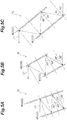
- FIGS. 5A to 5C are diagrams illustrating a case in which the mirror rotates in the ⁇ direction (within the X-Y plane).
- change in a reflection angle of the seed light L1 at the mirror M1 becomes the same as the change in the incidence angle according to a law of reflection.
- An angle when the seed light L1 reflected by the mirror M1 is incident on the mirror M2 is equal to the reflection angle at the mirror M1 because the mirrors M1 and M2 are parallel to each other.
- the reflection angle of the seed light L1 at the mirror M2 is equal to as the incidence angle thereof.
- FIGS. 6A and 6B are diagrams illustrating result of calculation of the amount of movement of the emission position of the seed light when the mirror is rotated in the ⁇ direction (within the X-Y plane). In the calculation of FIGS.
- a distance between the mirror M1 and the mirror M2 is 136.4 mm
- a thickness of the gain media 12A and 22A is 5 mm
- a refractive index of the gain media 12A and 22A is 1.82
- the incidence angle ⁇ of the seed light to the mirror M1 is 30°.
- FIGS. 6A and 6B are results when the mirrors M1 and M2 are rotated in a range of ⁇ 4° in the ⁇ direction in the Cartesian coordinate system S1 of FIG. 2 from the position of incidence of the seed light L1 on the mirror M1.
- the emission position of the seed light L1 moves in the Y direction of a Cartesian coordinate system S2 in FIG 4 .
- the emission direction of the seed light L1 does not change, as described above.
- FIGS. 7A and 7B are diagrams of a case in which a state in FIG. 2 is viewed in an X direction.
- the seed light L1 does not move in the Z direction of the Cartesian coordinate systems S1 and S2.
- the seed light L 1 is repeatedly reflected while moving in the Z direction.
- the seed light L1 slightly translates in a Y direction of the Cartesian coordinate system S2 of FIG. 3 .
- FIGS. 8A, 8B , 9A, and 9B are diagrams illustrating a calculation result of the amount of movement of the emission position of the seed light when the mirror is rotated in the ⁇ direction.
- the calculation result of FIGS. 8A and 8B are calculation results of the amount of movement of the emission position of the seed light in the Z direction when the mirrors M1 and M2 rotate in a range of ⁇ 4° in the ⁇ direction from the incidence position of the seed light L1 in the mirror M1.
- 9A and 9B are calculation results of the amount of movement of the emission position of the seed light in the Y direction (a Y direction in the Cartesian coordinate system S2) when the mirrors M1 and M2 rotate in a range of ⁇ 4° in the ⁇ direction from the incidence position of the seed light L1 in the mirror M1.
- the amount of movement of the emission position of the seed light L1 when the mirrors M1 and M2 rotate in the ⁇ direction is as illustrated in FIGS. 8A, 8B , 9A, and 9B .
- the direction of emission of the seed light L1 from the amplification unit 10 does not change.
- FIG. 10 is a graph illustrating position stability of the seed light. It is assumed in FIG 10 that vibrations of the mirrors M1 and M2 (the first laser medium 12 and the second laser medium 22) are periodic and sinusoidal. Further, it is assumed in FIG 10 that the mirrors M1 and M2 vibrate at a frequency of 10 Hz (a period of 100 ms) and with an amplitude of ⁇ 3 ° in the ⁇ direction. In this case, when it is assumed that a distance from the emission position of the seed light L1 in the mirror M2 to the mirror 45 is 4.3 m, a time until the seed light L1 is emitted from the mirror M2, reflected by the mirror 45, and incident on the mirror M2 again is about 28.7 ns. An amount by which the mirrors M1 and M2 vibrate and rotate during 28.7 ns is estimated to be about 5.4 ⁇ 10 -6 (°).
- An amount of position shift of the amplified seed light L1 when the seed light L1 propagates through the mirrors M1 and M2 rotated by 5.4 ⁇ 10 -6 (°) and returns to the same position as the incidence position of the seed light L1 in the mirror M1 is calculated as about ⁇ 0.5 nm.
- the amount of shift is greatly reduced to 0.0000013% of the beam diameter.
- the amount of movement of the emission position of the seed light L1 from the mirror M2 is +25.0 mm and -25.8 mm at ⁇ 3°, whereas the amount of movement of the emission position of the seed light L1 from the mirror M1 is reduced to 1/10 7 or less by being folded by the mirror 45 and propagating through the mirrors M2 and M1 again.
- the laser device according to the present invention is not limited to the laser device 1 described above, and various modifications are possible.
- the placement portion 11 a and the holding portion 11b separately formed may be mechanically fixed and integrated.
- the first laser medium 12 and the second laser medium 22 are disposed between the pair of plate members facing each other so that the mirrors M1 and M2 intersect (orthogonal to) facing surfaces of the plate members, and fixed to the plate members. That is, a holder that holds the first laser medium 12 and the second laser medium 22 so that the first laser medium 12 and the second laser medium 22 vibrate in synchronization with each other may be used as the holder 11.
- the mirror M1 and the mirror M2 may not be parallel to each other. Further, the first laser medium 12 and the second laser medium 22 may be disposed to entirely overlap each other when viewed in a direction intersecting (orthogonal to) the mirrors M1 and M2, or may be disposed not to overlap each other.
- gain media including Nd as an active element can also be used as the gain media 12A and 22A.
Landscapes
- Physics & Mathematics (AREA)
- Electromagnetism (AREA)
- Engineering & Computer Science (AREA)
- Plasma & Fusion (AREA)
- Optics & Photonics (AREA)
- Lasers (AREA)
Applications Claiming Priority (1)
| Application Number | Priority Date | Filing Date | Title |
|---|---|---|---|
| JP2018103634A JP7086720B2 (ja) | 2018-05-30 | 2018-05-30 | レーザ装置 |
Publications (3)
| Publication Number | Publication Date |
|---|---|
| EP3576232A2 true EP3576232A2 (de) | 2019-12-04 |
| EP3576232A3 EP3576232A3 (de) | 2020-02-05 |
| EP3576232B1 EP3576232B1 (de) | 2022-11-23 |
Family
ID=66668801
Family Applications (1)
| Application Number | Title | Priority Date | Filing Date |
|---|---|---|---|
| EP19176946.2A Active EP3576232B1 (de) | 2018-05-30 | 2019-05-28 | Laservorrichtung |
Country Status (3)
| Country | Link |
|---|---|
| US (1) | US11114810B2 (de) |
| EP (1) | EP3576232B1 (de) |
| JP (1) | JP7086720B2 (de) |
Citations (1)
| Publication number | Priority date | Publication date | Assignee | Title |
|---|---|---|---|---|
| JP2005327857A (ja) | 2004-05-13 | 2005-11-24 | Toyota Motor Corp | レーザ装置 |
Family Cites Families (17)
| Publication number | Priority date | Publication date | Assignee | Title |
|---|---|---|---|---|
| JPS6181580U (de) * | 1984-11-02 | 1986-05-30 | ||
| JPH09312430A (ja) * | 1996-05-22 | 1997-12-02 | Sadao Nakai | ジグザグスラブ固体レーザ及び増幅器 |
| US7299859B2 (en) * | 2003-04-28 | 2007-11-27 | Lucent Technologies Inc. | Temperature control of thermooptic devices |
| US7254152B2 (en) * | 2004-02-06 | 2007-08-07 | Hrl Laboratories, Llc | Optically pumped active mirror with improved performance and reduced parasitics |
| JP4074259B2 (ja) * | 2004-03-17 | 2008-04-09 | 浜松ホトニクス株式会社 | 半導体レーザ装置 |
| JP4627445B2 (ja) * | 2005-02-23 | 2011-02-09 | 浜松ホトニクス株式会社 | レーザ増幅装置 |
| JP5330801B2 (ja) * | 2008-11-04 | 2013-10-30 | 三菱重工業株式会社 | レーザ利得媒質、レーザ発振器及びレーザ増幅器 |
| US8509281B2 (en) * | 2010-02-11 | 2013-08-13 | The Boeing Company | Disk laser |
| EP2475054A1 (de) * | 2011-01-05 | 2012-07-11 | UAB "Ekspla" | Kollinear gepumptes aktives Medium mit mehreren dünnen Scheiben und zugehörige Pumpanordnung |
| JP6003323B2 (ja) * | 2012-07-18 | 2016-10-05 | 国立大学法人大阪大学 | レーザ媒質ユニット、レーザ増幅器及びレーザ発振器並びに冷却方法 |
| JP6331486B2 (ja) * | 2014-03-04 | 2018-05-30 | 国立大学法人大阪大学 | レーザ媒質ユニット、レーザ増幅器及びレーザ発振器 |
| JP6308965B2 (ja) * | 2015-03-26 | 2018-04-11 | 三菱重工業株式会社 | レーザ発振装置 |
| JP6632315B2 (ja) * | 2015-10-16 | 2020-01-22 | 三菱重工業株式会社 | 固体レーザ増幅装置 |
| JP6560954B2 (ja) * | 2015-10-16 | 2019-08-14 | 三菱重工業株式会社 | 固体レーザ増幅装置 |
| US20170254574A1 (en) * | 2016-03-01 | 2017-09-07 | Jay Eunjae Kim | Direct Cooling Platform With Vapor Compression Refrigeration Cycle And Applications Thereof |
| JP6678956B2 (ja) * | 2016-06-01 | 2020-04-15 | 国立大学法人大阪大学 | レーザ装置、レーザ増幅器及びレーザ発振器 |
| JP7021855B2 (ja) * | 2017-02-08 | 2022-02-17 | 浜松ホトニクス株式会社 | レーザ媒質ユニット、及び、レーザ装置 |
-
2018
- 2018-05-30 JP JP2018103634A patent/JP7086720B2/ja active Active
-
2019
- 2019-05-28 EP EP19176946.2A patent/EP3576232B1/de active Active
- 2019-05-29 US US16/424,709 patent/US11114810B2/en active Active
Patent Citations (1)
| Publication number | Priority date | Publication date | Assignee | Title |
|---|---|---|---|---|
| JP2005327857A (ja) | 2004-05-13 | 2005-11-24 | Toyota Motor Corp | レーザ装置 |
Also Published As
| Publication number | Publication date |
|---|---|
| EP3576232A3 (de) | 2020-02-05 |
| US20190372296A1 (en) | 2019-12-05 |
| JP7086720B2 (ja) | 2022-06-20 |
| US11114810B2 (en) | 2021-09-07 |
| JP2019207975A (ja) | 2019-12-05 |
| EP3576232B1 (de) | 2022-11-23 |
Similar Documents
| Publication | Publication Date | Title |
|---|---|---|
| JP5330801B2 (ja) | レーザ利得媒質、レーザ発振器及びレーザ増幅器 | |
| CN101416087B (zh) | 用于受激布里渊散射相位共轭镜的相位稳定装置以及使用该装置的光放大设备 | |
| US10862261B2 (en) | Laser medium unit and laser device | |
| JP2013218286A (ja) | ファラデーローテータ、光アイソレータ、レーザ装置、および極端紫外光生成装置 | |
| US8989224B2 (en) | Apparatus for femtosecond laser optically pumped by laser diode pumping module | |
| EP3657616B1 (de) | Festkörperlaser | |
| EP3576232B1 (de) | Laservorrichtung | |
| JPWO2003001634A1 (ja) | 励起モジュール、レーザ発振器およびレーザ増幅器 | |
| CN104885314B (zh) | 具有改进的时间衬比的用于放大激光脉冲的设备 | |
| US9209588B2 (en) | Disk laser | |
| KR20230119143A (ko) | 레이저 빔을 증폭시키기 위한 장치 | |
| JP2017216387A (ja) | レーザ装置、レーザ増幅器及びレーザ発振器 | |
| JP2019207989A (ja) | レーザ装置 | |
| US20240393609A1 (en) | Monolithic beamsplitter array | |
| CN111712974B (zh) | 激光振荡器单元和激光加工装置 | |
| CN101085493A (zh) | 激光振荡装置 | |
| Bolotnov et al. | Analysis of Ring Laser Gyro Errors during Path Length Active Stabilization | |
| JP2022026853A (ja) | レーザ装置 | |
| JP5400123B2 (ja) | レーザ発振装置 | |
| JP5991539B2 (ja) | レーザ発振装置及びレーザ加工機 | |
| JP2003258345A (ja) | スラブ型レーザ媒体を用いた高出力レーザ光発生装置 |
Legal Events
| Date | Code | Title | Description |
|---|---|---|---|
| PUAI | Public reference made under article 153(3) epc to a published international application that has entered the european phase |
Free format text: ORIGINAL CODE: 0009012 |
|
| STAA | Information on the status of an ep patent application or granted ep patent |
Free format text: STATUS: THE APPLICATION HAS BEEN PUBLISHED |
|
| AK | Designated contracting states |
Kind code of ref document: A2 Designated state(s): AL AT BE BG CH CY CZ DE DK EE ES FI FR GB GR HR HU IE IS IT LI LT LU LV MC MK MT NL NO PL PT RO RS SE SI SK SM TR |
|
| AX | Request for extension of the european patent |
Extension state: BA ME |
|
| RIN1 | Information on inventor provided before grant (corrected) |
Inventor name: IGUCHI, TAKUTO Inventor name: TAKEUCHI, YASUKI Inventor name: MORITA, TAKAAKI Inventor name: KATO, YOSHINORI Inventor name: SEKINE, TAKASHI Inventor name: HATANO, YUMA Inventor name: IYAMA, KOICHI |
|
| PUAL | Search report despatched |
Free format text: ORIGINAL CODE: 0009013 |
|
| AK | Designated contracting states |
Kind code of ref document: A3 Designated state(s): AL AT BE BG CH CY CZ DE DK EE ES FI FR GB GR HR HU IE IS IT LI LT LU LV MC MK MT NL NO PL PT RO RS SE SI SK SM TR |
|
| AX | Request for extension of the european patent |
Extension state: BA ME |
|
| RIC1 | Information provided on ipc code assigned before grant |
Ipc: H01S 3/02 20060101AFI20200102BHEP Ipc: H01S 3/16 20060101ALN20200102BHEP Ipc: H01S 3/04 20060101ALI20200102BHEP Ipc: H01S 3/23 20060101ALI20200102BHEP Ipc: H01S 3/042 20060101ALI20200102BHEP Ipc: H01S 3/06 20060101ALN20200102BHEP |
|
| STAA | Information on the status of an ep patent application or granted ep patent |
Free format text: STATUS: REQUEST FOR EXAMINATION WAS MADE |
|
| 17P | Request for examination filed |
Effective date: 20200803 |
|
| RBV | Designated contracting states (corrected) |
Designated state(s): AL AT BE BG CH CY CZ DE DK EE ES FI FR GB GR HR HU IE IS IT LI LT LU LV MC MK MT NL NO PL PT RO RS SE SI SK SM TR |
|
| STAA | Information on the status of an ep patent application or granted ep patent |
Free format text: STATUS: EXAMINATION IS IN PROGRESS |
|
| 17Q | First examination report despatched |
Effective date: 20210625 |
|
| RIC1 | Information provided on ipc code assigned before grant |
Ipc: H01S 3/16 20060101ALN20220429BHEP Ipc: H01S 3/06 20060101ALN20220429BHEP Ipc: H01S 3/23 20060101ALI20220429BHEP Ipc: H01S 3/042 20060101ALI20220429BHEP Ipc: H01S 3/04 20060101ALI20220429BHEP Ipc: H01S 3/02 20060101AFI20220429BHEP |
|
| GRAP | Despatch of communication of intention to grant a patent |
Free format text: ORIGINAL CODE: EPIDOSNIGR1 |
|
| STAA | Information on the status of an ep patent application or granted ep patent |
Free format text: STATUS: GRANT OF PATENT IS INTENDED |
|
| RIC1 | Information provided on ipc code assigned before grant |
Ipc: H01S 3/16 20060101ALN20220518BHEP Ipc: H01S 3/06 20060101ALN20220518BHEP Ipc: H01S 3/23 20060101ALI20220518BHEP Ipc: H01S 3/042 20060101ALI20220518BHEP Ipc: H01S 3/04 20060101ALI20220518BHEP Ipc: H01S 3/02 20060101AFI20220518BHEP |
|
| RIN1 | Information on inventor provided before grant (corrected) |
Inventor name: SEKINE, TAKASHI Inventor name: KATO, YOSHINORI Inventor name: IGUCHI, TAKUTO Inventor name: MORITA, TAKAAKI Inventor name: HATANO, YUMA Inventor name: TAKEUCHI, YASUKI Inventor name: IYAMA, KOICHI |
|
| INTG | Intention to grant announced |
Effective date: 20220621 |
|
| GRAS | Grant fee paid |
Free format text: ORIGINAL CODE: EPIDOSNIGR3 |
|
| GRAA | (expected) grant |
Free format text: ORIGINAL CODE: 0009210 |
|
| STAA | Information on the status of an ep patent application or granted ep patent |
Free format text: STATUS: THE PATENT HAS BEEN GRANTED |
|
| AK | Designated contracting states |
Kind code of ref document: B1 Designated state(s): AL AT BE BG CH CY CZ DE DK EE ES FI FR GB GR HR HU IE IS IT LI LT LU LV MC MK MT NL NO PL PT RO RS SE SI SK SM TR |
|
| REG | Reference to a national code |
Ref country code: GB Ref legal event code: FG4D |
|
| REG | Reference to a national code |
Ref country code: CH Ref legal event code: EP |
|
| REG | Reference to a national code |
Ref country code: AT Ref legal event code: REF Ref document number: 1533731 Country of ref document: AT Kind code of ref document: T Effective date: 20221215 Ref country code: DE Ref legal event code: R096 Ref document number: 602019022133 Country of ref document: DE |
|
| REG | Reference to a national code |
Ref country code: IE Ref legal event code: FG4D |
|
| REG | Reference to a national code |
Ref country code: LT Ref legal event code: MG9D |
|
| REG | Reference to a national code |
Ref country code: NL Ref legal event code: MP Effective date: 20221123 |
|
| REG | Reference to a national code |
Ref country code: AT Ref legal event code: MK05 Ref document number: 1533731 Country of ref document: AT Kind code of ref document: T Effective date: 20221123 |
|
| PG25 | Lapsed in a contracting state [announced via postgrant information from national office to epo] |
Ref country code: SE Free format text: LAPSE BECAUSE OF FAILURE TO SUBMIT A TRANSLATION OF THE DESCRIPTION OR TO PAY THE FEE WITHIN THE PRESCRIBED TIME-LIMIT Effective date: 20221123 Ref country code: PT Free format text: LAPSE BECAUSE OF FAILURE TO SUBMIT A TRANSLATION OF THE DESCRIPTION OR TO PAY THE FEE WITHIN THE PRESCRIBED TIME-LIMIT Effective date: 20230323 Ref country code: NO Free format text: LAPSE BECAUSE OF FAILURE TO SUBMIT A TRANSLATION OF THE DESCRIPTION OR TO PAY THE FEE WITHIN THE PRESCRIBED TIME-LIMIT Effective date: 20230223 Ref country code: LT Free format text: LAPSE BECAUSE OF FAILURE TO SUBMIT A TRANSLATION OF THE DESCRIPTION OR TO PAY THE FEE WITHIN THE PRESCRIBED TIME-LIMIT Effective date: 20221123 Ref country code: FI Free format text: LAPSE BECAUSE OF FAILURE TO SUBMIT A TRANSLATION OF THE DESCRIPTION OR TO PAY THE FEE WITHIN THE PRESCRIBED TIME-LIMIT Effective date: 20221123 Ref country code: ES Free format text: LAPSE BECAUSE OF FAILURE TO SUBMIT A TRANSLATION OF THE DESCRIPTION OR TO PAY THE FEE WITHIN THE PRESCRIBED TIME-LIMIT Effective date: 20221123 Ref country code: AT Free format text: LAPSE BECAUSE OF FAILURE TO SUBMIT A TRANSLATION OF THE DESCRIPTION OR TO PAY THE FEE WITHIN THE PRESCRIBED TIME-LIMIT Effective date: 20221123 |
|
| PG25 | Lapsed in a contracting state [announced via postgrant information from national office to epo] |
Ref country code: RS Free format text: LAPSE BECAUSE OF FAILURE TO SUBMIT A TRANSLATION OF THE DESCRIPTION OR TO PAY THE FEE WITHIN THE PRESCRIBED TIME-LIMIT Effective date: 20221123 Ref country code: PL Free format text: LAPSE BECAUSE OF FAILURE TO SUBMIT A TRANSLATION OF THE DESCRIPTION OR TO PAY THE FEE WITHIN THE PRESCRIBED TIME-LIMIT Effective date: 20221123 Ref country code: LV Free format text: LAPSE BECAUSE OF FAILURE TO SUBMIT A TRANSLATION OF THE DESCRIPTION OR TO PAY THE FEE WITHIN THE PRESCRIBED TIME-LIMIT Effective date: 20221123 Ref country code: IS Free format text: LAPSE BECAUSE OF FAILURE TO SUBMIT A TRANSLATION OF THE DESCRIPTION OR TO PAY THE FEE WITHIN THE PRESCRIBED TIME-LIMIT Effective date: 20230323 Ref country code: HR Free format text: LAPSE BECAUSE OF FAILURE TO SUBMIT A TRANSLATION OF THE DESCRIPTION OR TO PAY THE FEE WITHIN THE PRESCRIBED TIME-LIMIT Effective date: 20221123 Ref country code: GR Free format text: LAPSE BECAUSE OF FAILURE TO SUBMIT A TRANSLATION OF THE DESCRIPTION OR TO PAY THE FEE WITHIN THE PRESCRIBED TIME-LIMIT Effective date: 20230224 |
|
| P01 | Opt-out of the competence of the unified patent court (upc) registered |
Effective date: 20230517 |
|
| PG25 | Lapsed in a contracting state [announced via postgrant information from national office to epo] |
Ref country code: NL Free format text: LAPSE BECAUSE OF FAILURE TO SUBMIT A TRANSLATION OF THE DESCRIPTION OR TO PAY THE FEE WITHIN THE PRESCRIBED TIME-LIMIT Effective date: 20221123 |
|
| PG25 | Lapsed in a contracting state [announced via postgrant information from national office to epo] |
Ref country code: SM Free format text: LAPSE BECAUSE OF FAILURE TO SUBMIT A TRANSLATION OF THE DESCRIPTION OR TO PAY THE FEE WITHIN THE PRESCRIBED TIME-LIMIT Effective date: 20221123 Ref country code: RO Free format text: LAPSE BECAUSE OF FAILURE TO SUBMIT A TRANSLATION OF THE DESCRIPTION OR TO PAY THE FEE WITHIN THE PRESCRIBED TIME-LIMIT Effective date: 20221123 Ref country code: EE Free format text: LAPSE BECAUSE OF FAILURE TO SUBMIT A TRANSLATION OF THE DESCRIPTION OR TO PAY THE FEE WITHIN THE PRESCRIBED TIME-LIMIT Effective date: 20221123 Ref country code: DK Free format text: LAPSE BECAUSE OF FAILURE TO SUBMIT A TRANSLATION OF THE DESCRIPTION OR TO PAY THE FEE WITHIN THE PRESCRIBED TIME-LIMIT Effective date: 20221123 Ref country code: CZ Free format text: LAPSE BECAUSE OF FAILURE TO SUBMIT A TRANSLATION OF THE DESCRIPTION OR TO PAY THE FEE WITHIN THE PRESCRIBED TIME-LIMIT Effective date: 20221123 |
|
| REG | Reference to a national code |
Ref country code: DE Ref legal event code: R097 Ref document number: 602019022133 Country of ref document: DE |
|
| PG25 | Lapsed in a contracting state [announced via postgrant information from national office to epo] |
Ref country code: SK Free format text: LAPSE BECAUSE OF FAILURE TO SUBMIT A TRANSLATION OF THE DESCRIPTION OR TO PAY THE FEE WITHIN THE PRESCRIBED TIME-LIMIT Effective date: 20221123 Ref country code: AL Free format text: LAPSE BECAUSE OF FAILURE TO SUBMIT A TRANSLATION OF THE DESCRIPTION OR TO PAY THE FEE WITHIN THE PRESCRIBED TIME-LIMIT Effective date: 20221123 |
|
| PLBE | No opposition filed within time limit |
Free format text: ORIGINAL CODE: 0009261 |
|
| STAA | Information on the status of an ep patent application or granted ep patent |
Free format text: STATUS: NO OPPOSITION FILED WITHIN TIME LIMIT |
|
| 26N | No opposition filed |
Effective date: 20230824 |
|
| PG25 | Lapsed in a contracting state [announced via postgrant information from national office to epo] |
Ref country code: SI Free format text: LAPSE BECAUSE OF FAILURE TO SUBMIT A TRANSLATION OF THE DESCRIPTION OR TO PAY THE FEE WITHIN THE PRESCRIBED TIME-LIMIT Effective date: 20221123 |
|
| REG | Reference to a national code |
Ref country code: CH Ref legal event code: PL |
|
| PG25 | Lapsed in a contracting state [announced via postgrant information from national office to epo] |
Ref country code: MC Free format text: LAPSE BECAUSE OF FAILURE TO SUBMIT A TRANSLATION OF THE DESCRIPTION OR TO PAY THE FEE WITHIN THE PRESCRIBED TIME-LIMIT Effective date: 20221123 |
|
| REG | Reference to a national code |
Ref country code: BE Ref legal event code: MM Effective date: 20230531 |
|
| PG25 | Lapsed in a contracting state [announced via postgrant information from national office to epo] |
Ref country code: MC Free format text: LAPSE BECAUSE OF FAILURE TO SUBMIT A TRANSLATION OF THE DESCRIPTION OR TO PAY THE FEE WITHIN THE PRESCRIBED TIME-LIMIT Effective date: 20221123 Ref country code: LU Free format text: LAPSE BECAUSE OF NON-PAYMENT OF DUE FEES Effective date: 20230528 Ref country code: LI Free format text: LAPSE BECAUSE OF NON-PAYMENT OF DUE FEES Effective date: 20230531 Ref country code: CH Free format text: LAPSE BECAUSE OF NON-PAYMENT OF DUE FEES Effective date: 20230531 |
|
| REG | Reference to a national code |
Ref country code: IE Ref legal event code: MM4A |
|
| PG25 | Lapsed in a contracting state [announced via postgrant information from national office to epo] |
Ref country code: IE Free format text: LAPSE BECAUSE OF NON-PAYMENT OF DUE FEES Effective date: 20230528 |
|
| PG25 | Lapsed in a contracting state [announced via postgrant information from national office to epo] |
Ref country code: IE Free format text: LAPSE BECAUSE OF NON-PAYMENT OF DUE FEES Effective date: 20230528 |
|
| PG25 | Lapsed in a contracting state [announced via postgrant information from national office to epo] |
Ref country code: IT Free format text: LAPSE BECAUSE OF FAILURE TO SUBMIT A TRANSLATION OF THE DESCRIPTION OR TO PAY THE FEE WITHIN THE PRESCRIBED TIME-LIMIT Effective date: 20221123 Ref country code: BE Free format text: LAPSE BECAUSE OF NON-PAYMENT OF DUE FEES Effective date: 20230531 |
|
| PG25 | Lapsed in a contracting state [announced via postgrant information from national office to epo] |
Ref country code: BG Free format text: LAPSE BECAUSE OF FAILURE TO SUBMIT A TRANSLATION OF THE DESCRIPTION OR TO PAY THE FEE WITHIN THE PRESCRIBED TIME-LIMIT Effective date: 20221123 |
|
| PG25 | Lapsed in a contracting state [announced via postgrant information from national office to epo] |
Ref country code: BG Free format text: LAPSE BECAUSE OF FAILURE TO SUBMIT A TRANSLATION OF THE DESCRIPTION OR TO PAY THE FEE WITHIN THE PRESCRIBED TIME-LIMIT Effective date: 20221123 |
|
| PGFP | Annual fee paid to national office [announced via postgrant information from national office to epo] |
Ref country code: DE Payment date: 20250402 Year of fee payment: 7 |
|
| PGFP | Annual fee paid to national office [announced via postgrant information from national office to epo] |
Ref country code: GB Payment date: 20250401 Year of fee payment: 7 |
|
| PGFP | Annual fee paid to national office [announced via postgrant information from national office to epo] |
Ref country code: FR Payment date: 20250401 Year of fee payment: 7 |
|
| PG25 | Lapsed in a contracting state [announced via postgrant information from national office to epo] |
Ref country code: CY Free format text: LAPSE BECAUSE OF FAILURE TO SUBMIT A TRANSLATION OF THE DESCRIPTION OR TO PAY THE FEE WITHIN THE PRESCRIBED TIME-LIMIT; INVALID AB INITIO Effective date: 20190528 |
|
| PG25 | Lapsed in a contracting state [announced via postgrant information from national office to epo] |
Ref country code: HU Free format text: LAPSE BECAUSE OF FAILURE TO SUBMIT A TRANSLATION OF THE DESCRIPTION OR TO PAY THE FEE WITHIN THE PRESCRIBED TIME-LIMIT; INVALID AB INITIO Effective date: 20190528 |
|
| PG25 | Lapsed in a contracting state [announced via postgrant information from national office to epo] |
Ref country code: TR Free format text: LAPSE BECAUSE OF FAILURE TO SUBMIT A TRANSLATION OF THE DESCRIPTION OR TO PAY THE FEE WITHIN THE PRESCRIBED TIME-LIMIT Effective date: 20221123 |