EP3574802A1 - Wand für ein möbel oder möbelteil - Google Patents
Wand für ein möbel oder möbelteil Download PDFInfo
- Publication number
- EP3574802A1 EP3574802A1 EP19173714.7A EP19173714A EP3574802A1 EP 3574802 A1 EP3574802 A1 EP 3574802A1 EP 19173714 A EP19173714 A EP 19173714A EP 3574802 A1 EP3574802 A1 EP 3574802A1
- Authority
- EP
- European Patent Office
- Prior art keywords
- wall
- edge
- bead
- furniture
- bending
- Prior art date
- Legal status (The legal status is an assumption and is not a legal conclusion. Google has not performed a legal analysis and makes no representation as to the accuracy of the status listed.)
- Granted
Links
Images


Classifications
-
- A—HUMAN NECESSITIES
- A47—FURNITURE; DOMESTIC ARTICLES OR APPLIANCES; COFFEE MILLS; SPICE MILLS; SUCTION CLEANERS IN GENERAL
- A47B—TABLES; DESKS; OFFICE FURNITURE; CABINETS; DRAWERS; GENERAL DETAILS OF FURNITURE
- A47B88/00—Drawers for tables, cabinets or like furniture; Guides for drawers
- A47B88/90—Constructional details of drawers
-
- A—HUMAN NECESSITIES
- A47—FURNITURE; DOMESTIC ARTICLES OR APPLIANCES; COFFEE MILLS; SPICE MILLS; SUCTION CLEANERS IN GENERAL
- A47B—TABLES; DESKS; OFFICE FURNITURE; CABINETS; DRAWERS; GENERAL DETAILS OF FURNITURE
- A47B88/00—Drawers for tables, cabinets or like furniture; Guides for drawers
- A47B88/90—Constructional details of drawers
- A47B88/941—Drawers being constructed from two or more parts
-
- A—HUMAN NECESSITIES
- A47—FURNITURE; DOMESTIC ARTICLES OR APPLIANCES; COFFEE MILLS; SPICE MILLS; SUCTION CLEANERS IN GENERAL
- A47B—TABLES; DESKS; OFFICE FURNITURE; CABINETS; DRAWERS; GENERAL DETAILS OF FURNITURE
- A47B96/00—Details of cabinets, racks or shelf units not covered by a single one of groups A47B43/00 - A47B95/00; General details of furniture
-
- A—HUMAN NECESSITIES
- A47—FURNITURE; DOMESTIC ARTICLES OR APPLIANCES; COFFEE MILLS; SPICE MILLS; SUCTION CLEANERS IN GENERAL
- A47B—TABLES; DESKS; OFFICE FURNITURE; CABINETS; DRAWERS; GENERAL DETAILS OF FURNITURE
- A47B2210/00—General construction of drawers, guides and guide devices
- A47B2210/02—Drawers with hollow lateral walls in two parts
Definitions
- the invention relates to a wall, e.g. as a front wall, inner front wall, rear wall, side wall or screen, in particular for a discharge, such as e.g. a drawer or the like, consisting of metal, in particular of steel, as an L, U, C or hollow profile, with at least one edge whose outer radius is equal to or smaller than the material thickness of the profile.
- a wall e.g. as a front wall, inner front wall, rear wall, side wall or screen
- a discharge such as e.g. a drawer or the like, consisting of metal, in particular of steel, as an L, U, C or hollow profile, with at least one edge whose outer radius is equal to or smaller than the material thickness of the profile.
- a drawer side wall is known, the steel sheet is bent accordingly and then welded to a metal support profile, so that the side wall has sufficient torsional rigidity.
- the 10 2009 004 674 A1 relates to a device for bending a U or L sheet profile to an angular, in particular right-angled corner.
- From the AT 402 593 B is a drawer steel sheet with several bars known.
- the DE 39 34 419 A1 discloses a metal drawer side wall profile having a web wall forming the vertical side wall of the drawer.
- a sidewall profile is made of at least two sub-profiles folded from sheet metal, of which one sub-profile comprises the upper part of the web wall and the upper strip-shaped leg section and the other sub-profile comprises the lower part of the web wall and the lower strip-shaped leg which holds the drawer bottom.
- the sub-profiles are brought in a strip-shaped area in superimposition and interconnected.
- the EP 0 692 208 A1 shows a drawer with metallic drawer frames whose vertical webs form the side boundary of the drawer at least in the area of the drawer bottom and the bottom have a horizontal support web on which rests a bottom plate, wherein from the drawer racks several tabs are punched out and bent, with their free ends with are provided with a hole and the tabs between their junction with the support web and the hole have a kink, and the lobes are stiffer at kink than at the junction with the support web.
- the invention has for its object to provide a wall for a piece of furniture that has not been made by means of an extruded profile, but still has small radii, especially at the edges and corners.
- a wall wherein the wall as a front wall, inner front wall, rear wall, side wall or panel, in particular for a Ausschub, such as. a drawer or the like, is formed and made of metal, in particular steel, and by forming an L, U, C or hollow profile having at least one edge whose outer radius is equal to or smaller than the material thickness of the profile, wherein the Forming of the profile by means of an embossing is carried out, and / or wherein the edge is punched on the inner surface or the edge on the inner surface a bead is embossed.
- the metal is pressed into the area to be bent in a small radius, whereby the material is compacted in this area.
- the wall thickness is reduced in this area, so that during subsequent or simultaneously bending smaller radii can be generated.
- the metal is punched in the region of the edge to be provided on the inner surface or a bead is embossed. In this way, the edge or corner area is provided with the subsequent bending with a smaller radius as usual.
- Another significant advantage of the invention in one embodiment is that the material is cold-compacted during bending.
- the material has a higher strength in the bent region.
- the pressing of the material before or during bending takes place at room temperature and leads to an additional material compaction in the area to be bent.
- the bead is parallel to the edge, i.
- the bead runs after bending directly opposite the edge.
- the bead lies at a small distance laterally offset from the diagonal of the edge.
- the radius in the direction of the one side surface may be made larger than the radius to the other side surface, so that the curvature of the edge changes from one to the other side surface of the wall.
- the transition from one curvature to the other is advantageously continuous. In other words, the bend is offset from the bead.
- the shape of the edge is varied by the distance between 10% and 90%, in particular between 25% and 75% of the wall thickness.
- the curvature or the radius of the edge is influenced by the depth of the bead, which corresponds to 5% to 90%, in particular 20% to 80%, preferably 30% to 70% of the material thickness.
- width of the bead corresponds to 2% to 20%, in particular 4% to 10%, preferably 6% to 8% of the material thickness.
- more material can be re-pressed during forming, i. be pressed into a smaller radius of the die, since the wall thickness or material thickness is deformable.
- the bead is a saw cut or an embossment, so that the amount of material is set exactly to the needs of the bend.
- the invention also relates to a furniture or furniture part having a wall having one or more of the above features.
- Such furniture can be produced inexpensively and replace the variants of aluminum.
- the design of the furniture or furniture parts according to the invention are equal to those of aluminum, so that both embodiments can be used in combination.
- the sizes of the radii of both steel and aluminum variants are the same and do not differ.
- Excerpts, especially drawers or the like of furniture or pieces of furniture usually have a wall which is formed by a front wall, inner front wall, rear wall, side wall or panel.
- a front wall 10 is shown, but should not limit the invention.
- the front wall 10 is made of sheet steel and has an inner side 12, an outer side 14, an upper side 16 and a lower side 18, wherein the steel sheet is bent at the edges 20 such that the free, the underside 18 forming legs face each other, so that They can be welded, crimped, crimped, glued, screwed or riveted, for example.
- the inside 12 and the bottom 18 have openings 22 for attachment of the front wall 10 or for the cultivation of fittings or other furniture parts.
- FIG. 2 which has a cross section through the front wall 10 of the FIG. 1 shows, it can be seen that the formed steel sheet forms a hollow profile and the inner side 12 and outer side 14 and the upper side 16 and underside 18 each extend parallel to each other.
- the shape of the illustrated formed sheet steel is exemplary and other shapes are possible.
- the invention primarily relates to the design of at least one of the edges 20 or one of the in FIG. 1 shown corners 24.
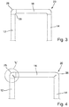
- FIG. 3 enlarged reproduced edge 20, via which the inner side 12 is connected to the top 16 or the top 16 to the outside 14, has an outer radius 26 and an inner radius 28, wherein primarily the outer radius 26 is visible to the user.
- the outer radius 26 represents a design element of the wall and in particular of the furniture or the furniture part.
- the edge 20 is produced by pressing in a correspondingly small outer radius 26 during bending. The material of the steel sheet is compressed and the desired profile is generated in the transformation area. The size of the outer radius 26 results in the embossing bending from the shape of the die, in which the steel sheet is pressed.
- the shape of the inner radius 28 is determined by the stamp. In this way, ie during embossing, smaller radii can be made than simply bending. The smaller radii then correspond to the radii, as in profiles produced by extrusion aluminum.
- FIG. 4 shows an alternative embodiment of the wall 10 of the invention, wherein the edge 20 was made on other or by additional measures.
- the wall 10 is also made of a formed sheet steel and also has an inner side 12 and an outer side 14 and a top 16 and a bottom 18 and forms a hollow profile, of which only a part is shown.
- the production of the edge 20 and in particular of the outer radius 26 will be described in the following FIGS. 5 and 6 explained in more detail.
- FIG. 5 is the section V according to FIG. 4 shown, wherein in solid line, the outer radius 26 is shown according to the invention.
- a dashed line shows an outer radius 30, as it arises by simply bending the steel sheet.
- the inner surface 32 of the steel sheet is provided with a bead 34, over which the thickness D of the steel sheet is reduced.
- the deeper the bead 34 penetrates into the steel sheet the smaller the outer radius 26 can be generated during the subsequent forming process.
- the bead 34 sawed into the inner surface 32 of the steel sheet and thereby material is removed. In the area of a corner 24, material is punched out, thereby creating the possibility of producing a corner 24 with a smaller outer radius 26 during forming.
- the bead 34 lies opposite the outer radius 26 and thus runs parallel to the edge 20.
- the edge 20 has both in the direction of the outer surface 36 of the upper side 16 and in the direction of the outer surface 38 of the inner side 12, the same outer radius 26.
- the edge 20 is thus mirror-symmetrical with respect to the diagonal 40th
- FIG. 6 shows a variant of the second embodiment of an edge 20, in which the outer radius 26A in the direction of the outer surface 36 of the upper side 16 is smaller than the outer radius 26B in the direction of the outer surface 38 of the inner side 12.
- the size of the outer radius 26A is about one-fifth the size of the outer radius 26B.
- the outer surfaces 36 and 38 are continuous in the radii 26A and 26B.
- the bead 34 is offset in this variant in the direction of outer radius 26A, i. it has a distance A to the bending center or diagonal 40 of the edge 20. This distance A also causes a displacement of the bead 34 to the center of the bending region, so that different outer radii 26 arise when the bending tool is offset with respect to the bead 34, i. the bead 34 is not centered in the tool.
Landscapes
- Cabinets, Racks, Or The Like Of Rigid Construction (AREA)
- Shaping Metal By Deep-Drawing, Or The Like (AREA)
Abstract
Description
- Die Erfindung betrifft eine Wand, z.B. als Frontwand, Innenfrontwand, Rückwand, Seitenwand oder Blende, insbesondere für einen Ausschub, wie z.B. eine Schublade oder dergleichen, bestehend aus Metall, insbesondere aus Stahl, als L-, U-, C oder Hohlprofil, mit wenigstens einer Kante, deren Außenradius gleich oder kleiner ist als die Materialdicke des Profils.
- Es ist allgemein bekannt, eine Wand, die sichtbar oder verdeckt als Möbelteil verwendet wird, aus Aluminium im Strangpressverfahren herzustellen. Dabei sind relativ kleine Radien an den Kanten möglich.
- Es ist außerdem bekannt, dass in der Sanitär- und Ladenbauindustrie Formteile, insbesondere Kassetten und Deckel mit seitlichen Aufkantungen, aus Blech hergestellt werden, die üblicherweise gebogen werden. Aus optischen Gründen ist es erwünscht, dass die äußeren Biegekanten möglichst scharfkantig und die Ecken spitz ausgeführt werden. Beim konventionellen Biegen entstehen Außenradien, die mindestens die Größe der Blechdicke aufweisen. Üblicherweise betragen die Außenradien das 1,5- bis 2-fache der Blechdicke. Um das gewünschte Erscheinungsbild zu erzielen werden die Kanten gegenwärtig spanend nachbearbeitet, oder die Winkel werden aus scharfkantig geschnittenen Einzelblechen zusammengefügt. In der
DE 20 2014 005 638 U1 werden scharfkantig und spitzeckig gebogenes Blechformteil offenbart, wobei der Außenradius der Biegekante kleiner ist als die Blechdicke des Ausgangsmaterials. Aus derWO 2017/106890 A1 ist eine Schubladenseitenwand bekannt, deren Stahlblech entsprechend gebogen und anschließend mit einem metallischen Trägerprofil verschweißt wird, sodass die Seitenwand eine ausreichende Verwindungssteifigkeit aufweist. Die10 2009 004 674 A1 AT 402 593 B DE 39 34 419 A1 offenbart ein Schubladen-Seitenwandprofil aus Metall mit einer die senkrechte Seitenwand der Schublade bildenden Stegwand. Ein Seitenwandprofil ist aus wenigstens zwei aus Metallblech gekanteten Teilprofilen hergestellt, von denen das eine Teilprofil den oberen Teil der Stegwand und den oberen streifenförmigen Schenkelabschnitt und das andere Teilprofil den unteren Teil der Stegwand und den unteren streifenförmigen, den Schubladenboden haltenden Schenkel umfasst. Die Teilprofile werden in einem streifenförmigen Bereich in Übereinanderlage gebracht und miteinander verbunden. - Die
EP 0 692 208 A1 zeigt eine Schublade mit metallischen Schubladenzargen, deren Vertikalstege die Seitenbegrenzung der Schublade zumindest im Bereich des Schubladenbodens bilden und die unten einen horizontalen Auflagesteg aufweisen, auf dem eine Bodenplatte aufliegt, wobei aus den Schubladenzargen mehrere Lappen ausgestanzt und ausgebogen sind, die bei ihren freien Enden mit einem Loch versehen sind und die Lappen zwischen ihrer Verbindungsstelle mit dem Auflagesteg und dem Loch einen Knick aufweisen, und die Lappen beim Knick steifer sind als an der Verbindungsstelle mit dem Auflagesteg. - Der Erfindung liegt die Aufgabe zugrunde eine Wand für ein Möbel bereit zu stellen, das nicht mittels eines Strangpressprofils hergestellt wurde, das aber dennoch kleine Radien aufweist, insbesondere an den Kanten und Ecken.
- Diese Aufgabe wird erfindungsgemäß mit einer Wand gelöst, wobei die Wand als Frontwand, Innenfrontwand, Rückwand, Seitenwand oder Blende, insbesondere für einen Ausschub, wie z.B. eine Schublade oder dergleichen, ausgebildet ist und aus Metall, insbesondere aus Stahl besteht, und durch Umformung ein L-, U-, C oder Hohlprofil aufweist, mit wenigstens einer Kante, deren Außenradius gleich oder kleiner ist als die Materialdicke des Profils, wobei die Umformung des Profils mittels einer Prägebiegung erfolgt, und/oder wobei die Kante auf der Innenfläche angestanzt oder der Kante auf der Innenfläche eine Sicke eingeprägt ist.
- Die Verwendung eines durch Umformen hergestellten L-, U-, C- oder Hohlprofils als Frontwand, Innenfrontwand, Rückwand, Seitenwand oder Blende, die aus Metall, insbesondere aus Stahl besteht, besitzt gemäß der Erfindung den wesentlichen Vorteil gegenüber stranggepressten Profilen, dass sie dünnwandig ausgebildet sein können und daher leicht sind, und dass deren Kanten und Ecken Radien aufweisen, die gleich oder kleiner sind, als die Wanddicke.
- Das Metall wird im umzubiegenden Bereich in einen kleinen Radius eingepresst, wodurch das Material in diesem Bereich verdichtet wird. Außerdem wird die Wandstärke in diesem Bereich verringert, so dass beim anschließenden oder gleichzeitig Biegen kleinere Radien erzeugt werden können.
- Alternativ wird das Metall im Bereich der vorzusehenden Kante auf der Innenfläche angestanzt oder es wird eine Sicke eingeprägt. Auf diese Weise wird der Kanten- oder Eckbereich beim anschließenden Umbiegen mit einem kleineren Radius wie üblich versehen.
- Ein weiterer wesentlicher Vorteil der Erfindung besteht bei einem Ausführungsbeispiel darin, dass das Material beim Umbiegen kaltverdichtet wird.
- Erfindungsgemäß weist das Material im gebogenen Bereich eine höhere Festigkeit auf. Das Verpressen des Materials vor oder während des Biegens erfolgt bei Zimmertemperatur und führt zu einer zusätzlichen Materialverdichtung im umzubiegenden Bereich.
- Dabei verläuft in bevorzugter Weise die Sicke parallel zur Kante, d.h. die Sicke verläuft nach dem Umbiegen direkt gegenüber der Kante. Bei einer anderen Variante liegt die Sicke mit geringem Abstand seitlich versetzt zur Diagonalen der Kante. Hierdurch kann gezielt auf die Formgebung des Radius Einfluss genommen werden. Dabei kann der Radius in Richtung der einen Seitenfläche größer gestaltet sein, als der Radius zur anderen Seitenfläche, so dass die Krümmung der Kante von der einen zur anderen Seitenfläche der Wand sich ändert. Der Übergang von der einen Krümmung zur anderen verläuft vorteilhaft stetig. Mit anderen Worten, verläuft die Biegung versetzt zur Sicke.
- Die Formgebung der Kante wird dadurch variiert, indem der Abstand zwischen 10% und 90%, insbesondere zwischen 25% und 75% der Wanddicke beträgt.
- Die Krümmung bzw. der Radius der Kante wird beeinflusst durch die Tiefe der Sicke, die 5 % bis 90%, insbesondere 20% bis 80%, vorzugsweise 30% bis 70% der Materialdicke entspricht.
- Scharfkantige Übergänge werden durch sehr tiefe Sicken erzielt.
- Eine andere Art der Formgebung der Kante wird dadurch erreicht, dass die Breite der Sicke 2% bis 20%, insbesondere 4% bis 10%, vorzugsweise 6% bis 8% der Materialdicke entspricht. Bei breiteren Sicken, kann beim Umformen mehr Material nachgepresst, d.h. in einen kleineren Radius der Matrize eingepresst werden, da die Wandstärke oder Materialstärke verformbarer ist.
- Bei Bedarf ist die Sicke ein Sägeschnitt oder eine Prägung, so dass die Menge an Material exakt auf die Bedürfnisse bei der Biegung eingestellt ist.
- Die Erfindung betrifft auch ein Möbel oder Möbelteil mit einer Wand, die eine oder mehrere der oben genannten Merkmale aufweist. Derartige Möbel können kostengünstig hergestellt werden und die Varianten aus Aluminium ersetzen. Das Design der erfindungsgemäßen Möbel oder Möbelteile sind gleich zu jenen aus Aluminium, so dass beide Ausführungsformen im Verbund eingesetzt werden können. Die Größen der Radien beider Varianten aus Stahl und Aluminium sind gleich und unterscheiden sich nicht.
- Weitere Merkmale und Vorteile ergeben sich aus der nachfolgenden Bescheidung, in der auf die Zeichnung Bezug genommen wird.
- In der Zeichnung zeigen:
- Figur 1
- eine perspektivische Ansicht einer Frontwand einer Schublade;
- Figur 2
- einen Querschnitt II - II durch die Frontwand der Schublade gemäß
Figur 1 ; - Figur 3
- eine vergrößerte Ansicht eines Ausschnitts III gemäß
Figur 2 nach einem ersten Ausführungsbeispiel; - Figur 4
- eine vergrößerte Ansicht eines Ausschnitts IV gemäß
Figur 2 nach einem zweiten, alternativen Ausführungsbeispiel; - Figur 5
- eine vergrößerte Ansicht eines Ausschnitts V gemäß
Figur 4 nach dem zweiten Ausführungsbeispiel; und - Figur 6
- eine vergrößerte Ansicht ähnlich wie in
Figur 5 , gemäß einer Variante des zweiten Ausführungsbeispiels. - Auszüge, insbesondere Schubladen oder dergleichen von Möbel oder Möbelstücken besitzen in der Regel eine Wand, die von einer Frontwand, Innenfrontwand, Rückwand, Seitenwand oder Blende gebildet wird. In der
Figur 1 ist beispielsweise eine Frontwand 10 dargestellt, die die Erfindung aber nicht einschränken soll. Die Frontwand 10 besteht aus Stahlblech und besitzt eine Innenseite 12, eine Außenseite 14, eine Oberseite 16 sowie eine Unterseite 18, wobei das Stahlblech an den Kanten 20 derart umgebogen ist, dass die freien, die Unterseite 18 bildenden Schenkel einander zugewandt sind, so dass sie z.B. verschweißt, verkrimpt, gebördelt, verklebt, verschraubt oder vernietet werden können. Die Innenseite 12 sowie die Unterseite 18 besitzen Öffnungen 22 zur Befestigung der Frontwand 10 oder zum Anbau von Beschlägen oder anderer Möbelteile. - Aus
Figur 2 , die einen Querschnitt durch die Frontwand 10 derFigur 1 zeigt, ist erkennbar, dass das umgeformte Stahlblech ein Hohlprofil bildet und die Innenseite 12 und Außenseite 14 sowie die Oberseite 16 und Unterseite 18 jeweils parallel zueinander verlaufen. Die Form des dargestellten, umgeformten Stahlblechs ist beispielhaft und andere Formen sind möglich. Die Erfindung bezieht sich primär auf die Ausgestaltung wenigstens einer der Kanten 20 oder einer der inFigur 1 gezeigten Ecken 24. - Die in
Figur 3 vergrößert wiedergegebene Kante 20, über welche die Innenseite 12 mit der Oberseite 16 oder die Oberseite 16 mit die Außenseite 14 verbunden ist, besitzt einen Außenradius 26 und einen Innenradius 28, wobei primär der Außenradius 26 für den Benutzer sichtbar ist. Der Außenradius 26 stellt ein Designelement der Wand und insbesondere des Möbels oder des Möbelteils dar. Die Kante 20 wird mittels Einpressen eines entsprechend kleinen Außenradius 26 beim Umbiegen hergestellt. Dabei wird das Material des Stahlbleches verdichtet und das gewünschte Profil im Umformungsbereich erzeugt. Die Größe des Außenradius 26 ergibt sich beim Prägebiegen aus der Form der Matrize, in welche das Stahlblech gepresst wird. Die Form des Innenradius 28 wird vom Stempel bestimmt. Auf diese Weise, d.h. beim Prägebiegen, können kleinere Radien hergestellt werden, als beim einfach Biegen. Die kleineren Radien entsprechen dann den Radien, wie bei mittels Strangpressverfahren hergestellten Profilen aus Aluminium. - Die
Figur 4 zeigt eine alternative Ausführungsform der erfindungsgemäßen Wand 10, wobei die Kante 20 auf andere oder durch zusätzliche Maßnahmen hergestellt wurde. Die Wand 10 besteht ebenfalls aus einem umgeformten Stahlblech und besitzt ebenfalls eine Innenseite 12 und eine Außenseite 14 sowie eine Oberseite 16 und eine Unterseite 18 und bildet ein Hohlprofil, von welchem lediglich ein Teil dargestellt ist. Die Herstellung der Kante 20 und insbesondere des Außenradius 26 wird in den nachfolgendenFiguren 5 und 6 näher erläutert. - In der
Figur 5 wird der Ausschnitt V gemäßFigur 4 gezeigt, wobei mit durchgezogener Linie der Außenradius 26 gemäß der Erfindung dargestellt ist. Mit gestrichelter Linie ist ein Außenradius 30 gezeigt, wie er durch einfaches Biegen des Stahlbleches entsteht. Vor dem Biegevorgang wird die Innenfläche 32 des Stahlbleches mit einer Sicke 34 versehen, über welche die Dicke D des Stahlblechs verringert wird. Je tiefer die Sicke 34 in das Stahlblech eindringt, desto kleiner kann der Außenradius 26 beim anschließenden Umformprozess erzeugt werden. Es besteht auch die Möglichkeit, dass die Sicke 34 in die Innenfläche 32 des Stahlbleches eingesägt und dadurch Material entfernt wird. Im Bereich einer Ecke 24 wird Material ausgestanzt und dadurch die Möglichkeit geschaffen, beim Umformen eine Ecke 24 mit kleinerem Außenradius 26 zu erzeugen. - In der
Figur 5 ist weiterhin erkennbar, dass die Sicke 34 dem Außenradius 26 gegenüber liegt und somit parallel zur Kante 20 verläuft. Die Kante 20 besitzt sowohl in Richtung der Außenfläche 36 der Oberseite 16 als auch der in Richtung der Außenfläche 38 der Innenseite 12 den gleichen Außenradius 26. Die Kante 20 ist somit spiegelsymmetrisch bezügliche der Diagonalen 40. - Die
Figur 6 zeigt eine Variante der zweiten Ausführungsform einer Kante 20, bei der der Außenradius 26A in Richtung der Außenfläche 36 der Oberseite 16 kleiner ist, als der Außenradius 26B in Richtung der Außenfläche 38 der Innenseite 12. Dabei beträgt bei dieser Variante die Größe des Außenradius 26A etwa ein Fünftel der Größe des Außenradius 26B. Außerdem gehen die Außenflächen 36 und 38 stetig in die Radien 26A und 26B über. - Die Sicke 34 ist bei dieser Variante in Richtung Außenradius 26A versetzt, d.h. sie besitzt einen Abstand A zur Biegemitte oder Diagonalen 40 der Kante 20. Dieser Abstand A verursacht auch einen Versatz der Sicke 34 zur Mitte des Biegebereichs, so dass unterschiedliche Außenradien 26 entstehen, wenn das Biegewerkzeug bezüglich der Sicke 34 versetzt ist, d.h. die Sicke 34 nicht mittig in Werkzeug liegt.
Claims (10)
- Wand als Frontwand (10), Innenfrontwand, Rückwand, Seitenwand oder Blende, insbesondere für einen Ausschub, wie z.B. eine Schublade oder dergleichen, bestehend aus Metall, insbesondere aus Stahl, als umgeformtes L-, U-, C- oder Hohlprofil, mit wenigstens einer Kante (20), deren Außenradius (26) gleich oder kleiner ist als die Materialdicke (D) des Profils, dadurch gekennzeichnet, dass die Umformung des Profils mittels einer Prägebiegung erfolgt, und/oder dass die Kante (20) auf der Innenfläche (32) angestanzt oder der Kante (20) auf der Innenfläche (32) eine Sicke (34) eingeprägt ist.
- Wand nach Anspruch 1, dadurch gekennzeichnet, dass das Material beim Biegen kaltverdichtet wird.
- Wand nach Anspruch 1 oder 2, dadurch gekennzeichnet, dass das Material im umgebogenen Bereich eine höhere Festigkeit aufweist.
- Wand nach einem der vorhergehenden Ansprüche, dadurch gekennzeichnet, dass die Sicke (34) nach dem Umbiegen parallel zur Kante (20) verläuft.
- Wand nach einem der vorhergehenden Ansprüche, dadurch gekennzeichnet, dass die Sicke (34) nach dem Umbiegen mit geringem Abstand zur Kante (20) verläuft.
- Wand nach Anspruch 5, dadurch gekennzeichnet, dass der Abstand zur Biegemitte zwischen 10% und 90%, insbesondere zwischen 25% und 75% der Materialdicke (d) beträgt.
- Wand nach einem der vorhergehenden Ansprüche, dadurch gekennzeichnet, dass die Tiefe der Sicke (34) 5 % bis 90%, insbesondere 20% bis 80%, vorzugsweise 30% bis 70% der Materialdicke (D) entspricht.
- Wand nach einem der vorhergehenden Ansprüche, dadurch gekennzeichnet, dass die Breite (B) der Sicke (34) 2% bis 20%, insbesondere 4% bis 10%, vorzugsweise 6% bis 8% der Materialdicke (D) entspricht.
- Wand nach einem der vorhergehenden Ansprüche, dadurch gekennzeichnet, dass die Sicke (34) ein Sägeschnitt oder eine Prägung ist.
- Möbel oder Möbelteil mit einer Wand (10) nach einem der vorhergehenden Ansprüche.
Applications Claiming Priority (1)
| Application Number | Priority Date | Filing Date | Title |
|---|---|---|---|
| DE202018103022.1U DE202018103022U1 (de) | 2018-05-30 | 2018-05-30 | Wand für ein Möbel oder Möbelteil |
Publications (2)
| Publication Number | Publication Date |
|---|---|
| EP3574802A1 true EP3574802A1 (de) | 2019-12-04 |
| EP3574802B1 EP3574802B1 (de) | 2023-09-06 |
Family
ID=66483873
Family Applications (1)
| Application Number | Title | Priority Date | Filing Date |
|---|---|---|---|
| EP19173714.7A Active EP3574802B1 (de) | 2018-05-30 | 2019-05-10 | Wand für ein möbel oder möbelteil |
Country Status (2)
| Country | Link |
|---|---|
| EP (1) | EP3574802B1 (de) |
| DE (1) | DE202018103022U1 (de) |
Citations (9)
| Publication number | Priority date | Publication date | Assignee | Title |
|---|---|---|---|---|
| DD86604A1 (de) * | 1970-11-17 | 1971-12-20 | ||
| DE3934419A1 (de) | 1989-10-14 | 1991-04-18 | Lautenschlaeger Kg Karl | Schubladen-seitenwandprofil aus metall |
| JPH06262267A (ja) * | 1993-03-10 | 1994-09-20 | Nisshin Steel Co Ltd | 溝形鋼の折り曲げ方法 |
| EP0692208A1 (de) | 1994-07-11 | 1996-01-17 | Julius Blum Gesellschaft m.b.H. | Schublade |
| AT402593B (de) | 1992-04-30 | 1997-06-25 | Blum Gmbh Julius | Schubladenzarge schubladenzarge |
| EP0826439A1 (de) * | 1996-09-02 | 1998-03-04 | Rudolf Tschopp | Verfahren zum Biegen eines Rohres, Vorrichtung zur Durchführung des Verfahrens sowie ein nach dem Verfahren hergestelltes Winkelstück |
| DE102009004674A1 (de) | 2009-01-12 | 2010-07-15 | Wuppermann Rohrtechnik Gmbh | Vorrichtung und Verfahren zum Biegen eines Profils und gebogenes Profil |
| DE202014005638U1 (de) | 2014-07-10 | 2015-10-13 | Benno Sörries KG | Biegen von Blechformteilen mit kleinem Außenradius |
| WO2017106890A1 (de) | 2015-12-22 | 2017-06-29 | Julius Blum Gmbh | Schubladenseitenwand |
Family Cites Families (2)
| Publication number | Priority date | Publication date | Assignee | Title |
|---|---|---|---|---|
| DE1854462U (de) * | 1961-10-05 | 1962-07-05 | Johann Keil Inh R Dannenberg | Gehaeuse, insbesondere fuer rundfunkgeraete. |
| DE9402770U1 (de) * | 1994-02-19 | 1994-05-19 | Grass AG, Höchst, Vorarlberg | Schublade |
-
2018
- 2018-05-30 DE DE202018103022.1U patent/DE202018103022U1/de not_active Expired - Lifetime
-
2019
- 2019-05-10 EP EP19173714.7A patent/EP3574802B1/de active Active
Patent Citations (9)
| Publication number | Priority date | Publication date | Assignee | Title |
|---|---|---|---|---|
| DD86604A1 (de) * | 1970-11-17 | 1971-12-20 | ||
| DE3934419A1 (de) | 1989-10-14 | 1991-04-18 | Lautenschlaeger Kg Karl | Schubladen-seitenwandprofil aus metall |
| AT402593B (de) | 1992-04-30 | 1997-06-25 | Blum Gmbh Julius | Schubladenzarge schubladenzarge |
| JPH06262267A (ja) * | 1993-03-10 | 1994-09-20 | Nisshin Steel Co Ltd | 溝形鋼の折り曲げ方法 |
| EP0692208A1 (de) | 1994-07-11 | 1996-01-17 | Julius Blum Gesellschaft m.b.H. | Schublade |
| EP0826439A1 (de) * | 1996-09-02 | 1998-03-04 | Rudolf Tschopp | Verfahren zum Biegen eines Rohres, Vorrichtung zur Durchführung des Verfahrens sowie ein nach dem Verfahren hergestelltes Winkelstück |
| DE102009004674A1 (de) | 2009-01-12 | 2010-07-15 | Wuppermann Rohrtechnik Gmbh | Vorrichtung und Verfahren zum Biegen eines Profils und gebogenes Profil |
| DE202014005638U1 (de) | 2014-07-10 | 2015-10-13 | Benno Sörries KG | Biegen von Blechformteilen mit kleinem Außenradius |
| WO2017106890A1 (de) | 2015-12-22 | 2017-06-29 | Julius Blum Gmbh | Schubladenseitenwand |
Also Published As
| Publication number | Publication date |
|---|---|
| DE202018103022U1 (de) | 2019-09-02 |
| EP3574802B1 (de) | 2023-09-06 |
Similar Documents
| Publication | Publication Date | Title |
|---|---|---|
| EP2569113B1 (de) | Verfahren zur herstellung von hohlprofilen mit einem längsflansch | |
| DE2545859A1 (de) | Verbindungs- und befestigungselement zum verbinden von werkstuecken aus weichem material, insbesondere duebel fuer spanplatten oder teile aus holz | |
| EP3714735B1 (de) | Schubladenseitenwand | |
| EP0003518B2 (de) | Verfahren zur Herstellung von Senklöchern in einem Beschlagteil aus Metall | |
| EP2456296B1 (de) | Weinbergpfahl | |
| DE69016668T2 (de) | Wandschiene, verfahren zu ihrer herstellung und gerät hierfür. | |
| EP1290307B1 (de) | Bauelement und verwendung eines bauelements sowie verfahren zur herstellung eines bauelements | |
| EP3574802B1 (de) | Wand für ein möbel oder möbelteil | |
| EP0886072B1 (de) | Hohlkörper, der aus mindestens einem Bauteil aus Flachmaterial besteht, und Verfahren zu seiner Herstellung | |
| AT393600B (de) | Schublade | |
| DE20013640U1 (de) | Spülebecken | |
| EP1476644A1 (de) | Verfahren zum herstellen einer auf das ende eines kraftfahrzeug-auspuffrohres aufsetzbaren blende und eine nach dem verfahren hergestellte blende | |
| DE3643741C2 (de) | Verfahren zum Herstellen eines Schrankgehäuses | |
| DE1554719A1 (de) | Bauteile und aus diesen hergestellte Konstruktionen,insbesondere Gehaeuse | |
| EP1416114B1 (de) | Verfahren zur Herstellung eines Fensterbankabschlusses | |
| EP1837095A2 (de) | Metallprofil für Rahmenkonstruktionen von Fenster-, Tür- oder Fassadenelementen sowie Verfahren zur Herstellung desselben | |
| DE9109283U1 (de) | Schalung für den Betonbau sowie Vorrichtung zum Herstellen der Schalung | |
| EP0888834B1 (de) | Verfahren zum Verbinden der Randbereiche eines oder mehrerer dünnwandiger Bauteile | |
| AT406235B (de) | Verfahren zum verbinden der randbereiche eines oder mehrerer dünnwandiger bauteile | |
| DE102005048992A1 (de) | Träger zum Aussteifen von Kunststoffhohlprofilen für Fenster- oder Türrahmen oder dergleichen | |
| AT1716U1 (de) | Vernieteter verbundkörper und verfahren zur herstellung einer nietverbindung | |
| DE19918196A1 (de) | Stellschraube | |
| EP4123098A1 (de) | Tragprofil für eine fassade | |
| DD289484A5 (de) | Verfahren zur herstellung von profilierten aushalsungen an blechen | |
| EP2689078A1 (de) | Profilelement und verfahren zum herstellen eines profilelements |
Legal Events
| Date | Code | Title | Description |
|---|---|---|---|
| PUAI | Public reference made under article 153(3) epc to a published international application that has entered the european phase |
Free format text: ORIGINAL CODE: 0009012 |
|
| STAA | Information on the status of an ep patent application or granted ep patent |
Free format text: STATUS: THE APPLICATION HAS BEEN PUBLISHED |
|
| AK | Designated contracting states |
Kind code of ref document: A1 Designated state(s): AL AT BE BG CH CY CZ DE DK EE ES FI FR GB GR HR HU IE IS IT LI LT LU LV MC MK MT NL NO PL PT RO RS SE SI SK SM TR |
|
| AX | Request for extension of the european patent |
Extension state: BA ME |
|
| STAA | Information on the status of an ep patent application or granted ep patent |
Free format text: STATUS: REQUEST FOR EXAMINATION WAS MADE |
|
| 17P | Request for examination filed |
Effective date: 20200604 |
|
| RBV | Designated contracting states (corrected) |
Designated state(s): AL AT BE BG CH CY CZ DE DK EE ES FI FR GB GR HR HU IE IS IT LI LT LU LV MC MK MT NL NO PL PT RO RS SE SI SK SM TR |
|
| STAA | Information on the status of an ep patent application or granted ep patent |
Free format text: STATUS: EXAMINATION IS IN PROGRESS |
|
| 17Q | First examination report despatched |
Effective date: 20210122 |
|
| GRAP | Despatch of communication of intention to grant a patent |
Free format text: ORIGINAL CODE: EPIDOSNIGR1 |
|
| STAA | Information on the status of an ep patent application or granted ep patent |
Free format text: STATUS: GRANT OF PATENT IS INTENDED |
|
| INTG | Intention to grant announced |
Effective date: 20230425 |
|
| P01 | Opt-out of the competence of the unified patent court (upc) registered |
Effective date: 20230519 |
|
| GRAS | Grant fee paid |
Free format text: ORIGINAL CODE: EPIDOSNIGR3 |
|
| GRAA | (expected) grant |
Free format text: ORIGINAL CODE: 0009210 |
|
| STAA | Information on the status of an ep patent application or granted ep patent |
Free format text: STATUS: THE PATENT HAS BEEN GRANTED |
|
| AK | Designated contracting states |
Kind code of ref document: B1 Designated state(s): AL AT BE BG CH CY CZ DE DK EE ES FI FR GB GR HR HU IE IS IT LI LT LU LV MC MK MT NL NO PL PT RO RS SE SI SK SM TR |
|
| REG | Reference to a national code |
Ref country code: GB Ref legal event code: FG4D Free format text: NOT ENGLISH |
|
| REG | Reference to a national code |
Ref country code: CH Ref legal event code: EP |
|
| REG | Reference to a national code |
Ref country code: DE Ref legal event code: R096 Ref document number: 502019009213 Country of ref document: DE |
|
| REG | Reference to a national code |
Ref country code: IE Ref legal event code: FG4D Free format text: LANGUAGE OF EP DOCUMENT: GERMAN |
|
| REG | Reference to a national code |
Ref country code: LT Ref legal event code: MG9D |
|
| REG | Reference to a national code |
Ref country code: NL Ref legal event code: MP Effective date: 20230906 |
|
| PG25 | Lapsed in a contracting state [announced via postgrant information from national office to epo] |
Ref country code: GR Free format text: LAPSE BECAUSE OF FAILURE TO SUBMIT A TRANSLATION OF THE DESCRIPTION OR TO PAY THE FEE WITHIN THE PRESCRIBED TIME-LIMIT Effective date: 20231207 |
|
| PG25 | Lapsed in a contracting state [announced via postgrant information from national office to epo] |
Ref country code: SE Free format text: LAPSE BECAUSE OF FAILURE TO SUBMIT A TRANSLATION OF THE DESCRIPTION OR TO PAY THE FEE WITHIN THE PRESCRIBED TIME-LIMIT Effective date: 20230906 Ref country code: RS Free format text: LAPSE BECAUSE OF FAILURE TO SUBMIT A TRANSLATION OF THE DESCRIPTION OR TO PAY THE FEE WITHIN THE PRESCRIBED TIME-LIMIT Effective date: 20230906 Ref country code: NO Free format text: LAPSE BECAUSE OF FAILURE TO SUBMIT A TRANSLATION OF THE DESCRIPTION OR TO PAY THE FEE WITHIN THE PRESCRIBED TIME-LIMIT Effective date: 20231206 Ref country code: LV Free format text: LAPSE BECAUSE OF FAILURE TO SUBMIT A TRANSLATION OF THE DESCRIPTION OR TO PAY THE FEE WITHIN THE PRESCRIBED TIME-LIMIT Effective date: 20230906 Ref country code: LT Free format text: LAPSE BECAUSE OF FAILURE TO SUBMIT A TRANSLATION OF THE DESCRIPTION OR TO PAY THE FEE WITHIN THE PRESCRIBED TIME-LIMIT Effective date: 20230906 Ref country code: HR Free format text: LAPSE BECAUSE OF FAILURE TO SUBMIT A TRANSLATION OF THE DESCRIPTION OR TO PAY THE FEE WITHIN THE PRESCRIBED TIME-LIMIT Effective date: 20230906 Ref country code: GR Free format text: LAPSE BECAUSE OF FAILURE TO SUBMIT A TRANSLATION OF THE DESCRIPTION OR TO PAY THE FEE WITHIN THE PRESCRIBED TIME-LIMIT Effective date: 20231207 Ref country code: FI Free format text: LAPSE BECAUSE OF FAILURE TO SUBMIT A TRANSLATION OF THE DESCRIPTION OR TO PAY THE FEE WITHIN THE PRESCRIBED TIME-LIMIT Effective date: 20230906 |
|
| PG25 | Lapsed in a contracting state [announced via postgrant information from national office to epo] |
Ref country code: NL Free format text: LAPSE BECAUSE OF FAILURE TO SUBMIT A TRANSLATION OF THE DESCRIPTION OR TO PAY THE FEE WITHIN THE PRESCRIBED TIME-LIMIT Effective date: 20230906 |
|
| PG25 | Lapsed in a contracting state [announced via postgrant information from national office to epo] |
Ref country code: IS Free format text: LAPSE BECAUSE OF FAILURE TO SUBMIT A TRANSLATION OF THE DESCRIPTION OR TO PAY THE FEE WITHIN THE PRESCRIBED TIME-LIMIT Effective date: 20240106 |
|
| PG25 | Lapsed in a contracting state [announced via postgrant information from national office to epo] |
Ref country code: ES Free format text: LAPSE BECAUSE OF FAILURE TO SUBMIT A TRANSLATION OF THE DESCRIPTION OR TO PAY THE FEE WITHIN THE PRESCRIBED TIME-LIMIT Effective date: 20230906 |
|
| PG25 | Lapsed in a contracting state [announced via postgrant information from national office to epo] |
Ref country code: SM Free format text: LAPSE BECAUSE OF FAILURE TO SUBMIT A TRANSLATION OF THE DESCRIPTION OR TO PAY THE FEE WITHIN THE PRESCRIBED TIME-LIMIT Effective date: 20230906 Ref country code: RO Free format text: LAPSE BECAUSE OF FAILURE TO SUBMIT A TRANSLATION OF THE DESCRIPTION OR TO PAY THE FEE WITHIN THE PRESCRIBED TIME-LIMIT Effective date: 20230906 Ref country code: IS Free format text: LAPSE BECAUSE OF FAILURE TO SUBMIT A TRANSLATION OF THE DESCRIPTION OR TO PAY THE FEE WITHIN THE PRESCRIBED TIME-LIMIT Effective date: 20240106 Ref country code: ES Free format text: LAPSE BECAUSE OF FAILURE TO SUBMIT A TRANSLATION OF THE DESCRIPTION OR TO PAY THE FEE WITHIN THE PRESCRIBED TIME-LIMIT Effective date: 20230906 Ref country code: EE Free format text: LAPSE BECAUSE OF FAILURE TO SUBMIT A TRANSLATION OF THE DESCRIPTION OR TO PAY THE FEE WITHIN THE PRESCRIBED TIME-LIMIT Effective date: 20230906 Ref country code: CZ Free format text: LAPSE BECAUSE OF FAILURE TO SUBMIT A TRANSLATION OF THE DESCRIPTION OR TO PAY THE FEE WITHIN THE PRESCRIBED TIME-LIMIT Effective date: 20230906 Ref country code: PT Free format text: LAPSE BECAUSE OF FAILURE TO SUBMIT A TRANSLATION OF THE DESCRIPTION OR TO PAY THE FEE WITHIN THE PRESCRIBED TIME-LIMIT Effective date: 20240108 Ref country code: SK Free format text: LAPSE BECAUSE OF FAILURE TO SUBMIT A TRANSLATION OF THE DESCRIPTION OR TO PAY THE FEE WITHIN THE PRESCRIBED TIME-LIMIT Effective date: 20230906 |
|
| PG25 | Lapsed in a contracting state [announced via postgrant information from national office to epo] |
Ref country code: PL Free format text: LAPSE BECAUSE OF FAILURE TO SUBMIT A TRANSLATION OF THE DESCRIPTION OR TO PAY THE FEE WITHIN THE PRESCRIBED TIME-LIMIT Effective date: 20230906 |
|
| REG | Reference to a national code |
Ref country code: DE Ref legal event code: R097 Ref document number: 502019009213 Country of ref document: DE |
|
| PG25 | Lapsed in a contracting state [announced via postgrant information from national office to epo] |
Ref country code: DK Free format text: LAPSE BECAUSE OF FAILURE TO SUBMIT A TRANSLATION OF THE DESCRIPTION OR TO PAY THE FEE WITHIN THE PRESCRIBED TIME-LIMIT Effective date: 20230906 |
|
| PLBE | No opposition filed within time limit |
Free format text: ORIGINAL CODE: 0009261 |
|
| STAA | Information on the status of an ep patent application or granted ep patent |
Free format text: STATUS: NO OPPOSITION FILED WITHIN TIME LIMIT |
|
| PG25 | Lapsed in a contracting state [announced via postgrant information from national office to epo] |
Ref country code: DK Free format text: LAPSE BECAUSE OF FAILURE TO SUBMIT A TRANSLATION OF THE DESCRIPTION OR TO PAY THE FEE WITHIN THE PRESCRIBED TIME-LIMIT Effective date: 20230906 Ref country code: SI Free format text: LAPSE BECAUSE OF FAILURE TO SUBMIT A TRANSLATION OF THE DESCRIPTION OR TO PAY THE FEE WITHIN THE PRESCRIBED TIME-LIMIT Effective date: 20230906 |
|
| 26N | No opposition filed |
Effective date: 20240607 |
|
| PG25 | Lapsed in a contracting state [announced via postgrant information from national office to epo] |
Ref country code: BG Free format text: LAPSE BECAUSE OF FAILURE TO SUBMIT A TRANSLATION OF THE DESCRIPTION OR TO PAY THE FEE WITHIN THE PRESCRIBED TIME-LIMIT Effective date: 20230906 |
|
| PG25 | Lapsed in a contracting state [announced via postgrant information from national office to epo] |
Ref country code: BG Free format text: LAPSE BECAUSE OF FAILURE TO SUBMIT A TRANSLATION OF THE DESCRIPTION OR TO PAY THE FEE WITHIN THE PRESCRIBED TIME-LIMIT Effective date: 20230906 |
|
| REG | Reference to a national code |
Ref country code: CH Ref legal event code: PL |
|
| PG25 | Lapsed in a contracting state [announced via postgrant information from national office to epo] |
Ref country code: MC Free format text: LAPSE BECAUSE OF FAILURE TO SUBMIT A TRANSLATION OF THE DESCRIPTION OR TO PAY THE FEE WITHIN THE PRESCRIBED TIME-LIMIT Effective date: 20230906 |
|
| PG25 | Lapsed in a contracting state [announced via postgrant information from national office to epo] |
Ref country code: LU Free format text: LAPSE BECAUSE OF NON-PAYMENT OF DUE FEES Effective date: 20240510 |
|
| GBPC | Gb: european patent ceased through non-payment of renewal fee |
Effective date: 20240510 |
|
| PG25 | Lapsed in a contracting state [announced via postgrant information from national office to epo] |
Ref country code: MC Free format text: LAPSE BECAUSE OF FAILURE TO SUBMIT A TRANSLATION OF THE DESCRIPTION OR TO PAY THE FEE WITHIN THE PRESCRIBED TIME-LIMIT Effective date: 20230906 Ref country code: LU Free format text: LAPSE BECAUSE OF NON-PAYMENT OF DUE FEES Effective date: 20240510 Ref country code: CH Free format text: LAPSE BECAUSE OF NON-PAYMENT OF DUE FEES Effective date: 20240531 |
|
| REG | Reference to a national code |
Ref country code: BE Ref legal event code: MM Effective date: 20240531 |
|
| PG25 | Lapsed in a contracting state [announced via postgrant information from national office to epo] |
Ref country code: IE Free format text: LAPSE BECAUSE OF NON-PAYMENT OF DUE FEES Effective date: 20240510 |
|
| PG25 | Lapsed in a contracting state [announced via postgrant information from national office to epo] |
Ref country code: BE Free format text: LAPSE BECAUSE OF NON-PAYMENT OF DUE FEES Effective date: 20240531 |
|
| PG25 | Lapsed in a contracting state [announced via postgrant information from national office to epo] |
Ref country code: FR Free format text: LAPSE BECAUSE OF NON-PAYMENT OF DUE FEES Effective date: 20240531 |
|
| PG25 | Lapsed in a contracting state [announced via postgrant information from national office to epo] |
Ref country code: GB Free format text: LAPSE BECAUSE OF NON-PAYMENT OF DUE FEES Effective date: 20240510 |
|
| PGFP | Annual fee paid to national office [announced via postgrant information from national office to epo] |
Ref country code: DE Payment date: 20250523 Year of fee payment: 7 |
|
| PGFP | Annual fee paid to national office [announced via postgrant information from national office to epo] |
Ref country code: IT Payment date: 20250404 Year of fee payment: 7 |
|
| PGFP | Annual fee paid to national office [announced via postgrant information from national office to epo] |
Ref country code: AT Payment date: 20250526 Year of fee payment: 7 |
|
| PG25 | Lapsed in a contracting state [announced via postgrant information from national office to epo] |
Ref country code: CY Free format text: LAPSE BECAUSE OF FAILURE TO SUBMIT A TRANSLATION OF THE DESCRIPTION OR TO PAY THE FEE WITHIN THE PRESCRIBED TIME-LIMIT; INVALID AB INITIO Effective date: 20190510 |
|
| PG25 | Lapsed in a contracting state [announced via postgrant information from national office to epo] |
Ref country code: HU Free format text: LAPSE BECAUSE OF FAILURE TO SUBMIT A TRANSLATION OF THE DESCRIPTION OR TO PAY THE FEE WITHIN THE PRESCRIBED TIME-LIMIT; INVALID AB INITIO Effective date: 20190510 |