EP3573441B1 - Work machine - Google Patents
Work machine Download PDFInfo
- Publication number
- EP3573441B1 EP3573441B1 EP17892443.7A EP17892443A EP3573441B1 EP 3573441 B1 EP3573441 B1 EP 3573441B1 EP 17892443 A EP17892443 A EP 17892443A EP 3573441 B1 EP3573441 B1 EP 3573441B1
- Authority
- EP
- European Patent Office
- Prior art keywords
- frame
- base
- pair
- columns
- rail
- Prior art date
- Legal status (The legal status is an assumption and is not a legal conclusion. Google has not performed a legal analysis and makes no representation as to the accuracy of the status listed.)
- Active
Links
- 238000000034 method Methods 0.000 description 14
- 230000033001 locomotion Effects 0.000 description 11
- 230000000694 effects Effects 0.000 description 10
- 238000004519 manufacturing process Methods 0.000 description 6
- 239000000758 substrate Substances 0.000 description 5
- 238000001816 cooling Methods 0.000 description 3
- 238000009434 installation Methods 0.000 description 3
- 239000000725 suspension Substances 0.000 description 3
- 239000000470 constituent Substances 0.000 description 2
- 230000001629 suppression Effects 0.000 description 2
- 238000005452 bending Methods 0.000 description 1
- 230000005540 biological transmission Effects 0.000 description 1
- 230000007423 decrease Effects 0.000 description 1
- 230000001419 dependent effect Effects 0.000 description 1
- 238000007689 inspection Methods 0.000 description 1
- 230000015654 memory Effects 0.000 description 1
- 229910000679 solder Inorganic materials 0.000 description 1
- 238000011144 upstream manufacturing Methods 0.000 description 1
Images


Classifications
-
- H—ELECTRICITY
- H05—ELECTRIC TECHNIQUES NOT OTHERWISE PROVIDED FOR
- H05K—PRINTED CIRCUITS; CASINGS OR CONSTRUCTIONAL DETAILS OF ELECTRIC APPARATUS; MANUFACTURE OF ASSEMBLAGES OF ELECTRICAL COMPONENTS
- H05K13/00—Apparatus or processes specially adapted for manufacturing or adjusting assemblages of electric components
- H05K13/04—Mounting of components, e.g. of leadless components
- H05K13/0404—Pick-and-place heads or apparatus, e.g. with jaws
- H05K13/0406—Drive mechanisms for pick-and-place heads, e.g. details relating to power transmission, motors or vibration damping
-
- H—ELECTRICITY
- H05—ELECTRIC TECHNIQUES NOT OTHERWISE PROVIDED FOR
- H05K—PRINTED CIRCUITS; CASINGS OR CONSTRUCTIONAL DETAILS OF ELECTRIC APPARATUS; MANUFACTURE OF ASSEMBLAGES OF ELECTRICAL COMPONENTS
- H05K13/00—Apparatus or processes specially adapted for manufacturing or adjusting assemblages of electric components
- H05K13/04—Mounting of components, e.g. of leadless components
- H05K13/0452—Mounting machines or lines comprising a plurality of tools for guiding different components to the same mounting place
-
- B—PERFORMING OPERATIONS; TRANSPORTING
- B25—HAND TOOLS; PORTABLE POWER-DRIVEN TOOLS; MANIPULATORS
- B25J—MANIPULATORS; CHAMBERS PROVIDED WITH MANIPULATION DEVICES
- B25J9/00—Programme-controlled manipulators
- B25J9/02—Programme-controlled manipulators characterised by movement of the arms, e.g. cartesian coordinate type
-
- H—ELECTRICITY
- H05—ELECTRIC TECHNIQUES NOT OTHERWISE PROVIDED FOR
- H05K—PRINTED CIRCUITS; CASINGS OR CONSTRUCTIONAL DETAILS OF ELECTRIC APPARATUS; MANUFACTURE OF ASSEMBLAGES OF ELECTRICAL COMPONENTS
- H05K13/00—Apparatus or processes specially adapted for manufacturing or adjusting assemblages of electric components
- H05K13/04—Mounting of components, e.g. of leadless components
- H05K13/0404—Pick-and-place heads or apparatus, e.g. with jaws
- H05K13/0408—Incorporating a pick-up tool
- H05K13/0409—Sucking devices
-
- H—ELECTRICITY
- H05—ELECTRIC TECHNIQUES NOT OTHERWISE PROVIDED FOR
- H05K—PRINTED CIRCUITS; CASINGS OR CONSTRUCTIONAL DETAILS OF ELECTRIC APPARATUS; MANUFACTURE OF ASSEMBLAGES OF ELECTRICAL COMPONENTS
- H05K13/00—Apparatus or processes specially adapted for manufacturing or adjusting assemblages of electric components
- H05K13/04—Mounting of components, e.g. of leadless components
- H05K13/0404—Pick-and-place heads or apparatus, e.g. with jaws
- H05K13/0411—Pick-and-place heads or apparatus, e.g. with jaws having multiple mounting heads
-
- Y—GENERAL TAGGING OF NEW TECHNOLOGICAL DEVELOPMENTS; GENERAL TAGGING OF CROSS-SECTIONAL TECHNOLOGIES SPANNING OVER SEVERAL SECTIONS OF THE IPC; TECHNICAL SUBJECTS COVERED BY FORMER USPC CROSS-REFERENCE ART COLLECTIONS [XRACs] AND DIGESTS
- Y10—TECHNICAL SUBJECTS COVERED BY FORMER USPC
- Y10T—TECHNICAL SUBJECTS COVERED BY FORMER US CLASSIFICATION
- Y10T29/00—Metal working
- Y10T29/53—Means to assemble or disassemble
- Y10T29/5313—Means to assemble electrical device
- Y10T29/53174—Means to fasten electrical component to wiring board, base, or substrate
Definitions
- the present invention relates to a work machine.
- JP-A-2012-044128 discloses, as a work machine for performing various types of work by moving a head, a component mounter for mounting electronic components on circuit boards.
- guide devices for moving a head in such a work machine there are guide devices which are of a suspension type in which a moving body of the guide device is supported by being suspended from a rail.
- Such suspension type guide devices have a configuration like one described, for example, in JP-A-2012-044128 , in which a pair of rails and a drive device for applying a driving force to the moving body are disposed on a frame spanning a front column and a rear column.
- JP-A-2012-033736 proposes to provide a mounting machine capable of improving the mounting position accuracy of a suspended-type head unit.
- a mounting machine comprises: a first head unit (second head unit) which mounts an electronic component on a substrate; a support frame which is arranged above the first head unit (second head unit) and supports the first head unit (second head unit); direct-acting bearings which are arranged on an underside of the support frame and guide the movement of the first head unit (second head unit); and a Y-actuator which is arranged to protrude above a top face of the support frame and moves the first head unit (second head unit) along the direct-acting bearings.
- JP-A-2012-033736 discloses work machines according to the preambles of independent claims 1 and 5.
- US 2006/042075 A1 discloses a substrate conveyor-positioner unit for conveying and positioning a substrate in an X direction is arranged on a supporting base.
- Supporting frames are arranged in a standing manner on both ends in a Y direction being orthogonal to the X direction on the supporting base.
- a component supplying unit is arranged on at least one end side in the Y direction on the supporting base.
- a plurality of Y-axis tables is laid between upper ends of the both supporting frames at an appropriate interval.
- An X-axis table is attached to a movable portion of each Y-axis table.
- An operating head for holding a component by suction at the component supplying unit and for mounting the component on the substrate on the substrate conveyor-positioner unit is attached to a movable portion of the X-axis table. Moreover, a height of upper ends of the supporting frames is located below eyes of a worker to enable the worker to visually confirm conditions of mounting operations.
- An object of the present description is to provide a work machine which improves the rigidity of the entire machine to reduce the effect of vibrations caused by a moving head thereof.
- a first work machine including: a base; a pair of rear columns provided on left and right sides of a rear portion of the base; a frame structure spanning the pair of front columns and the pair of rear columns; a first head and a second head both configured to perform predetermined work in movable ranges defined so as not to overlap each other above the base; a first guide device provided on the frame structure on a left side of the center of the base in a left-right direction thereof and configured to allow the first head to move in a front-rear direction of the base, and a second guide device provided on the frame structure on a right side of the center of the base in the left-right direction thereof and configured to allow the second head to move in the front-rear direction of the base; wherein the first guide device further comprises: a first left rail and a first right rail both extending in the front-rear direction
- a second work machine including: a base; a pair of front columns provided on left and right sides of a front portion of the base; a pair of rear columns provided on left and right sides of a rear portion of the base; a frame structure spanning the pair of front columns and the pair of rear columns; a first head configured to perform predetermined work in a movable range defined above the base, and a first guide device provided on the frame structure and configured to allow the first head to move in a front-rear direction of the base, wherein the first guide device further comprises: a first left rail and a first right rail both extending in the front-rear direction of the base, the first left rail and the first right rail being parallel, and a first moving body, being provided so as to move in the front-rear direction of the base, while being suspended from the first left rail and the first right rail, and supporting the first head, wherein the frame structure further comprises: a left frame in which the first left rail of the first guide device is provided at a lower portion thereof; a right
- the pair of front columns and the pair of rear columns are connected together by the frame structure including the left and right frames, the front and rear frames, and the center frame.
- the work machine improves the overall rigidity of the work machine with the structural rigidity of the frame structure while maintaining the overall external dimensions of the work machine.
- the frequency of vibrations caused in association with movement of the first head and the second head can be increased, which facilitates suppressing and controlling the vibrations.
- the effect of the vibrations can be reduced to thereby improve the working efficiency of the work machine.
- the frame structure supports the first guide device and the second guide device, which are both suspended, as a result of the rails being provided individually at the lower portions of the left frame, the right frame, and the center frame.
- the work machine can reliably bear the loads of the first guide device and the second guide device and suppress the occurrence of vibrations that would otherwise be caused in association with movement of the first head and the second head.
- the pair of front columns and the pair of rear columns are connected together by the frame structure including the left and right frames and the front and rear frames.
- the work machine improves the overall rigidity of the work machine with the structural rigidity of the frame structure while maintaining the overall external dimensions of the work machine.
- the frame structure supports the first guide device, which is suspended, with the individual rails provided at the lower portions of the left frame and the right frame.
- a work machine performs various types of work by moving a head.
- the work machine is described as a component mounter.
- the component mounter is a production device for producing board products by mounting electronic components in predetermined mounting positions on circuit boards.
- a "circuit board” will simply be referred to as a "board”
- an electronic component will simply be referred to as a "component”.
- each component mounter 1 includes base 2, board conveyance device 10, component supply device 20, two component transfer devices 30, front column member 60, rear column member 70, frame structure 80, control device 90, and the like.
- a horizontal width direction of component mounter 1 (a direction directed from an upper left to a lower right in Fig 1 ) is referred to as an X-axis direction or a left-right direction.
- a horizontal depth direction of component mounter 1 (a direction directed from a lower left to an upper right in Fig. 1 ) is referred to as a Y-axis direction or a front-rear direction.
- a vertical direction perpendicular to an X-axis and a Y-axis (an up-down direction in Fig. 1 ) is referred to as a Z-axis direction or an up-down direction.
- Board conveyance device 10 is placed on base 2 and is made up of a belt conveyor or the like. Board conveyance device 10 conveys boards Bd sequentially in a conveyance direction (in an X-axis direction in this embodiment). Board conveyance device 10 locates board Bd in a predetermined position inside component mounter 1. Then, after component mounter 1 has performed a mounting process on board Bd, board conveyance device 10 conveys board Bd so processed outside of component mounter 1.
- Component supply device 20 is placed on base 2 and supplies components to be mounted on boards Bd.
- Component supply device 20 includes multiple feeders 21 that are set individually in multiple slots disposed side by side in the X-axis direction in a replaceable fashion.
- a carrier tape installing with a number of components is wound around supply reel 22 and is loaded in each feeder 21.
- Feeder 21 feeds out the carrier tape to supply a component to a supply position located at a distal end of feeder 21 so that the component can be picked up there.
- Each of two component transfer devices 30 is used for a mounting process of picking up a component supplied by component supply device 20 and then mounting the component on board Bd.
- two component transfer devices 30 are disposed to be aligned side by side in the left-right direction of component mounter 1 and are supported by frame structure 80. The detailed configuration of two component transfer devices 30 will be described later.
- front column member 60 includes pair of front columns 61 and connecting member 62. Pair of front columns 61 are provided at left and right sides of a front portion of base 2. In this embodiment, pair of front columns 61 are connected together at front end portions by connecting member 62 extending in a left-right direction of base 2 to form an integral portal-like structure.
- Rear column member 70 is disposed separated from front column member 60 in the front-rear direction of base 2.
- Rear column member 70 includes pair of rear columns 71 and a connecting member 72. Pair of rear columns 71 are provided at left and right sides of a rear portion of base 2. In this embodiment, pair of rear columns 71 are connected together by connecting member 72 extending in the left-right direction of base 2 to form an integral portal-like structure.
- Frame structure 80 spans pair of front columns 61 and pair of rear columns 71.
- Frame structure 80 is a strength member configured not only to support two component transfer devices 30 but also to connect front column member 60 and rear column member 70 together to thereby improve the overall rigidity of the work machine. A detailed configuration of frame structure 80 will be described later.
- Control device 90 is made up mainly of CPU, various memories, and a control circuit. Control device 90 executes a mounting process of mounting components on boards Bd. The mounting process is executed based on a control program and constitutes a pick and place cycle of picking up a component supplied by component supply device 20 and transferring the component to a predetermined mounting position on board Bd repeatedly multiple times.
- control device 90 when controlling the operation of mounting heads 35, which will be described later, control device 90 receives information outputted from various sensors provided in component mounter 1, and the result of a recognition process by image processing or the like. Then, the control device sends control signals to component transfer devices 30 based on the control program, information from the various sensors, and the results of the various recognition processes. As a result, positions and angles of components held by mounting heads 35 are controlled.
- control device 90 suppresses and controls vibrations generated in association with the operation of mounting heads 35. For example, when moving mounting head 35 to a position above a mounting position while executing the mounting process, control device 90 calculates the time it takes until the amplitude of vibration generated in association with the movement of mounting head 35 is dampened to be equal to or less than an allowable value based on a starting position and an ending position of the movement of mounting head 35, a traveling speed of mounting head 35, a mass of the moving member, and the like. Then, after having waited for the calculated dampening time to elapse, control device 90 lowers suction nozzle 36 holding a component and mounts the component in a predetermined mounting position on board Bd. An improvement in the accuracy of the mounting process is achieved by executing the mounting process while controlling the vibration in the way described above.
- frame structure 80 is highly rigid, frame structure 80 being a frame structure connecting front column member 60 and rear column member 70 provided on base 2 and supporting two component transfer devices 30.
- component transfer device 30 includes Y-axis guide device 31, linear motor 32, X-axis guide device 33, and mounting head 35.
- Y-axis guide device 31 moves mounting head 35 in a front-rear direction (a Y-axis direction) of base 2.
- Y-axis guide device 31 includes pair of guide rails 311, four guide blocks 312, and Y-axis moving body 313. Pair of guide rails 311 is made up of left rail 311L and right rail 311R that both extend in the front-rear direction of base 2 and are disposed parallel to each other.
- Y-axis moving body 313 is fixed to lower portions of four guide blocks 312. As a result, Y-axis moving body 313 can move in the front-rear direction of base 2 while being suspended from left rail 311L and right rail 311R.
- Y-axis guide device 31 is of a suspension type in which Y-axis moving body 313 is supported while being suspended from pair of guide rails 311, allowing a large movable range to be ensured in a left-right direction.
- Linear motor 32 includes motor shaft 321, motor block 322, and cooling device 323.
- Motor shaft 321 is a fixed member that is disposed parallel to pair of guide rails 311 in a space defined in the Y-axis direction between pair of guide rails 311.
- Multiple ring-like permanent magnets are disposed on motor shaft 321 along an axial direction. The multiple permanent magnets are disposed in such a manner that magnetic poles of two adjacent magnets differ from each other.
- Motor block 322 is a movable device that is disposed on motor shaft 321 so as to slide over motor shaft 321 in a direction in which motor shaft 321 extends.
- Motor block 322 include multiple inductors that are disposed along the extending direction of motor shaft 321.
- Cooling device 323 is made up of a heat conductive pipe, a fan, and the like, all of which are not illustrated. Cooling device 323 dissipates heat generated as a result of driving of linear motor 32 to an exterior portion to thereby cool linear motor 32.
- Y-axis moving body 313 of Y-axis guide device 31 is fixed to a lower portion of motor block 322 of linear motor 32.
- Linear motor 32 generates a thrust by feeding the inductors of motor block 322.
- Linear motor 32 moves Y-axis moving body 313 fixed to motor block 322 to a predetermined position in the Y-axis direction by controlling the feeding of the inductors.
- X-axis guide device 33 moves mounting head 35 in a left-right direction (an X-axis direction) of base 2.
- X-axis guide device 33 includes X-axis rail 331 and X-axis moving body 332.
- X-axis rail 331 is disposed on Y-axis moving body 313 in such a manner as to extend in the X-axis direction.
- X-axis moving body 332 is in slidable engagement with X-axis rail 331.
- X-axis moving body 332 is moved to a predetermined position in the X-axis direction by a drive device, not illustrated.
- a drive device for example, a ball screw device or a linear motor can be applied.
- Mounting head 35 is fixed to X-axis moving body 332 by a clamp, not illustrated.
- Mounting head 35 includes multiple suction nozzles 36 that are provided detachably.
- Mounting head 35 supports suction nozzles 36 individually in such a manner as to be revolved around an R axis parallel to a Z axis and lifted up and down.
- the lifting and lowering position and angle of each suction nozzle 36 relative to mounting head 35, along with the supply of negative pressure, are controlled.
- each suction nozzle 36 picks up through suction a component supplied by feeder 21 of component supply device 20.
- Two component transfer devices 30 that are configured in the way described above are disposed to be aligned side by side in the X-axis direction and are allowed to operate independently of each other.
- respective mounting heads 35 of two component transfer devices 30 individually mount components on boards Bd in corresponding movable ranges Rm1, Rm2 that are defined above base 2 so as not to overlap each other.
- movable ranges Rm1, Rm2 are ranges determined by a mechanical configuration of Y-axis guide device 31 and X-axis guide device 33 and are defined as a range that encircles mounting head 35 when moving mounting head 35 to both left and right ends and both front and rear ends.
- Figs. 3 and 4 illustrate respective movable ranges Rm1, Rm2 of two component transfer devices 30 in the X-axis direction.
- Y-axis guide device 31 is also referred to as first guide device 40, linear motor 32 as first drive device 45, and mounting head 35 as first head 46.
- Left rail 311L and right rail 311R that constitute pair of guide rails 311 of first guide device 40 are also referred to as first left rail 41 and first right rail 42, respectively.
- Y-axis guide device 31 is also referred to as second guide device 50, linear motor 32 as second drive device 55, and mounting head 35 as second head 56.
- Left rail 311L and right rail 311R that constitute pair of guide rails 311 of second guide device 50 are also referred to as second left rail 51 and second right rail 52, respectively.
- frame structure 80 is fixed to front column member 60 and rear column member 70, which each have an integral portal-like structure, while spanning these column members.
- frame structure 80 has a rectangular shape that surrounds an outer circumference of component mounter 1 when viewed from above.
- Frame structure 80 has a box-like shape that is opened downwards and upwards to thereby ensure structural rigidity thereof.
- frame structure 80 includes left frame 81, right frame 82, center frame 83, front frame 84, rear frame 85, and the like.
- Left frame 81 extends in the front-rear direction (the Y-axis direction) of base 2 and spans a space defined between a left end portion of front column 60 and a left end portion of rear column member 70.
- the external shape of a cross section at right angles to the Y-axis direction extends in an up-down direction.
- First left rail 41 of first guide device 40 is provided at a lower portion of left frame 81.
- Right frame 82 is axially symmetric with left frame 81 with respect to the center of base 2 in the left-right direction thereof as a center line. As illustrated in Fig. 3 , right frame 82 extends in the front-rear direction (the Y-axis direction) of base 2 and spans a space defined between a right end portion of front column member 60 and a right end portion of rear column member 70. As illustrated in Fig. 4 , in right frame 82, the external shape of a cross section at right angles to the Y-axis direction extends in the up-down direction. Second right rail 52 of second guide device 50 is provided at a lower portion of right frame 82.
- center frame 83 is disposed between left frame 81 and right frame 82 in the X-axis direction.
- Center frame 83 extends in the Y-axis direction and spans a space defined between a center portion of front column member 60 and a center portion of rear column member 70.
- the external shape of a cross section at right angles to the Y-axis direction has a rectangular shape that extends in the up-down direction.
- First right rail 42 of first guide device 40 and second left rail 51 of second guide device 50 are provided at a lower portion of center frame 83.
- front frame 84 and rear frame 85 extend in the X-axis direction, and in each of front frame 84 and rear frame 85, the external shape of a cross section at right angles to the X-axis direction extends in the up-down direction.
- Front frame 84 connects respective upper portions of pair of front columns 61 together and also connects respective front end portions of left frame 81, right frame 82, and center frame 83 together.
- Rear frame 85 connects respective upper portions of pair of rear columns 71 and also connects respective rear ends of left frame 81, right frame 82, and center frame 83 together.
- pair of front columns 61 are connected together by connecting member 62 to thereby form front column member 60, which has an integral portal-like structure.
- pair of rear columns 71 are connected together by connecting member 72 to thereby form rear column member 70, which has an integral portal-like structure.
- an outer frame of frame structure 80 connects together left frame 81, right frame 82, front frame 84, and rear frame 85 each having almost the same width in the up-down direction.
- center frame 83 is disposed between left frame 81 and right frame 82, fabricating a structure that increases the rigidity further.
- the cross sections of frames 81 to 86 are elongated in the up-down direction increasing the modulus of sectional shape, thereby increasing the bending rigidity of frame structure 80.
- frequencies in the X-axis direction and the Y-axis direction of vibrations generated in association with movement of first head 46 and second head 56 can be increased.
- frame structure 80 ensures the rigidity in the X-axis direction required for frame structure 80 (for example, the rigidity with which a frequency of vibration in the X-axis direction that is generated by a specified operation of mounting head 35 reaches a threshold value or greater) with front frame 84 and rear frame 85.
- frame structure 80 includes no other member configured to connect left frame 81 and right frame 82 together other than front frame 84 and rear frame 85.
- a reduction in weight of frame structure 80 as well as a reduction in production cost and installation cost of frame structure 80 is achieved.
- frame structure 80 has the box-like shape that is opened in the up-down direction and ensures a space for installing first drive device 45 between left frame 81 and center frame 83 and a space for installing second drive device 55 between right frame 82 and center frame 83.
- first drive device 45 is disposed between left frame 81 and center frame 83 in the X-axis direction and is supported at both end portions in the front-rear direction of base 2 by front frame 84 and rear frame 85.
- second drive device 55 is disposed between right frame 82 and center frame 83 in the X-axis direction and is supported at both end portions in the front-rear direction of base 2 thereof by front frame 84 and rear frame 85.
- first drive device 45 and second drive device 55 which are both linear motors 32, are supported at both end portions of motor shafts 321 thereof in the Y-axis direction by front frame 84 and rear frame 85. Then, first drive device 45 applies a driving force for moving first head 46 in the front-rear direction of base 2 to first moving body 43. Similarly, second drive device 55 applies a driving force for moving second head 56 in the front-rear direction of base 2 to second moving body 53.
- first left rail 41 of first guide device 40 is provided at the lower portion of left frame 81.
- first left rail 41 is disposed within a range where movable range Rm1 of first head 46 overlaps support range Rs in the left-right direction of base 2 where pair of front columns 61 and pair of rear columns 71 are connected to frame structure 80.
- inner end faces of left front column 61 and left rear column 71 are indicated by broken lines.
- Second right rail 52 of second guide device 50 is provided at the lower portion of right frame 82.
- second right rail 52 is disposed within a range where movable range Rm2 of second head 56 overlaps support range Rs in the left-right direction of base 2 where pair of front columns 61 and pair of rear columns 71 are connected to frame structure 80.
- inner end faces of right front column 61 and right rear column 71 are indicated by broken lines.
- support ranges Rs are ranges in the X-axis direction where frame structure 80 connects to front column member 60 and rear column member 70.
- Support ranges Rs correspond to ranges represented by a range in the X-axis direction where left frame 81 is supported directly or indirectly by one of the pair of front columns 61 and one of the pair of rear columns 71 and a range in the X-axis direction where right frame 82 is supported directly or indirectly by the other of the pair front columns 61 and the other of the pair of rear columns 71.
- a downward load exerted to left frame 81 from first left rail 41 is generally transmitted to left front column 61 and left rear column 71 that reside in support range Rs as a buckling load.
- a downward load exerted to right frame 82 from second right rail 52 is generally transmitted to right front column 61 and right rear column 71 that reside in support range Rs as a buckling load.
- first guide device 40 and second guide device 50 which generate vibrations as movement occurs, are supported with the buckling strengths of front column member 60 and rear column member 70 via frame structure 80.
- the overall structural rigidity of component mounter 1 is increased, thereby not only suppressing the generation of vibrations but also increasing the frequency of generated vibrations.
- First right rail 42 of first guide device 40 and second left rail 51 of second guide device 50 are provided at the lower portion of center frame 83.
- first right rail 42 is disposed inside movable range Rm1 of first head 46 in the X-axis direction.
- second left rail 51 is disposed inside movable range Rm2 of second head 56 in the X-axis direction.
- pair of front columns 61 and pair of rear columns 71 both have side surfaces 611, 711, on both sides in the left-right direction (the X-axis direction) of base 2, constituting the same flat plane.
- This configuration is designed to enable installation of component mounter 1 as close to another adjacent component mounter 1 as possible as illustrated in Fig. 1 when a production line including component mounters 1 is configured.
- the production line including component mounters 1 can be shortened to thereby improve the productivity per unit area in an assembling facility.
- pair of left and right connecting plates 89 are disposed on side surfaces 611 of pair of front columns 61 and side surfaces 711 of pair of rear columns 71 to connect side surfaces (611, 711) together.
- component mounter 1 increases its overall rigidity in the front-rear direction by making use of the tensile strength of connecting plates 89. Consequently, this configuration increases particularly the rigidity in the Y-axis direction, increasing the frequency in the Y-axis direction of vibrations generated as first head 46 and second head 56 move.
- first guide device 40 and second guide device 50 which are suspended, are supported by providing individual rails (41, 42, 51, 52) at the lower portions of left frame 81, right frame 82, and center frame 83.
- component mounter 1 reliably bears the loads of first guide device 40 and second guide device 50 with base 2, front column member 60, rear column member 70, and frame structure 80, making it possible to suppress the occurrence of vibrations that would otherwise be caused as first head 46 and second head 56 move.
- a work machine (component mounter 101) of a second embodiment differs from component mounter 1 of the first embodiment mainly in the configuration of frame structure 80. Since other common configurations are substantially the same as those of the first embodiment, detailed descriptions thereof will be omitted.
- component mounter 101 includes base 102, board conveyance device 10, component supply device 20 (omitted in Fig. 5 ), one component transfer device 30 (first guide device 140), front column member 160, rear column member 170, frame structure 180, control device 90, and the like.
- component mounter 101 of this embodiment has only one component transfer device 30. Due to this, compared with component mounter 1 of the first embodiment, widths in an X-axis direction of component mounter 101 and base 102 are generally half of those of component mounter 1.
- Component transfer device 30 of this embodiment is of the same type as two component transfer devices 30 of the first embodiment and includes first guide device 140, first drive device 145, first head 146, and the like.
- Front column member 160 has an integral portal-like structure, which has pair of front columns 61, provided at left and right sides of a front portion of base 102, connected by connecting member 162 extending in the X-axis direction.
- rear column member 170 has an integral portal-like structure, which has pair of rear columns 71 provided at left and right sides of a rear portion of base 102 connected by connecting member 172 extending in the X-axis direction.
- Frame structure 180 is a strength member that supports one component transfer device 30 and improves the overall rigidity of component mounter 101 by connecting front column member 160 and rear column member 170 together.
- Frame structure 180 has a similar configuration to the configuration of frame structure 80 of the first embodiment except that center frame 83 is removed from or is not provided on frame structure 180 and includes left frame 81, right frame 82, front frame 84, rear frame 85, and the like.
- first left rail 41 of first guide device 140 is provided at a lower portion of left frame 81.
- First right rail 42 of first guide device 140 is provided at a lower portion of right frame 82.
- front frame 84 connects pair of front columns 61 together and also connects respective front ends of left frame 81 and right frame 82 together.
- Rear frame 85 connects pair of rear columns 71 together and also connects respective rear ends of left frame 81 and right frame 82.
- first left rail 41 and first right rail 42 of first guide device 140 are disposed within ranges where movable range Rm1 of first head 46 overlaps support ranges Rs in a left-right direction of base 102 where pair of first front columns 61 and pair of rear columns 71 are connected to frame structure 180.
- inner end faces pair of front columns 61 and pair of rear columns 71 are indicated by broken lines.
- First drive device 145 is disposed between left frame 81 and right frame 82. As illustrated in Fig. 5 , first drive device 145 is supported at both end portions in the front-rear direction of base 102 by front frame 84 and rear frame 85. Specifically, first drive device 145, which is a linear motor 32, is supported at both end portions of motor shaft 321 in a Y-axis direction by front frame 84 and rear frame 85. First drive device 145 applies a driving force, to first moving body 43, for moving first head 146 in the front-rear direction of base 102.
- a downward load exerted to frame structure 180 from first guide device 140 is generally transmitted to pair of front columns 61 and pair of rear columns 71 that both reside in support ranges Rs as a buckling load.
- first guide device 140 which can generate vibrations as it operates, is supported with the bucking strengths of front column member 160 and rear column member 170 via frame structure 180.
- component mounter 101 not only is the generation of vibrations suppressed by increasing the overall structural rigidity of component mounter 101, but also the frequency of generated vibrations is increased.
- component mounter 101 With the configuration of component mounter 101 described above, pair of front columns 61 and pair of rear columns 71 are connected together by frame structure 180. As a result, in component mounter 101, the overall rigidity thereof is improved by the structural rigidity of frame structure 180 while maintaining the overall external dimensions of component mounter 101. Thus, the frequency of vibrations generated as first head 146 moves can be increased. As a result, suppression and control of the vibrations are facilitated, thereby reducing the effect of the vibrations and improving working accuracy.
- first guide device 140 which is suspended, is supported by providing the individual rails (41, 42) at the lower portions of left frame 81 and right frame 82.
- the load of first guide device 140 can be reliably borne by base 102, front column member 160, rear column member 170, and frame structure 180, thereby making it possible to suppress the generation of vibrations that would otherwise be caused as first head 146 moves.
- frame structures 80, 180 have a box-like shape that is opened downwards and upwards.
- frame structures 80, 180 may have, for example, a shape that is covered with a plate or a cover member at the upper side thereof.
- front column members 60, 160 form an integral portal-like structure as a result of pair of front columns 61 being connected together by connecting members 62, 162.
- front column members 60, 160 need not have connecting members 62, 162 and may be connected together only at upper portions thereof by frame structures 80, 180.
- rear column members 70, 170 need not have connecting members 72, 172 and may be connected together only at upper portions thereof by frame structures 80, 180.
- the aspects exemplified in the first embodiment and the second embodiment are desirable.
- pair of connecting plates 89 are individually made to connect the respective side surfaces (611, 711) of pair of front columns 61 and pair of rear columns 71 together.
- side surfaces 801 on both the sides in the X-axis direction may both constitute the same planar shape as the side surfaces (611, 711), and pair of front columns 61 and pair of rear columns 71 may be connected together by pair of connecting plates 89.
- connecting plates 89 may be made to connect the side surfaces of bases 2 and 102.
- first drive devices 45, 145 and second drive device 55 are each described as being linear motor 32.
- a linear motion device such as a ball screw device may be applied to first drive devices 45, 145 and second drive device 55, as long as the linear motion device can apply, to first moving body 43 and second moving body 53, a driving force for moving first heads 46, 146 and second head 56 in the front-rear direction (the Y-axis direction) of bases 2, 102.
- first drive devices 45, 145 and second drive device 55 are each made up of a ball screw device, both end portions of a threaded shaft are supported by front frame 84 and rear frame 85.
- the work machine is described as forming component mounters 1, 101 for producing board products.
- the work machine may be of various types of work machines other than the component mounter, as long as such work machines are limited by the appended claims and such that various types of work are performed by moving the head.
- the work machine may be a solder printer that constitutes a production line together with component mounters 1, 101 or an inspection device configured to inspect circuit boards on which components are mounted.
Description
- The present invention relates to a work machine.
-
JP-A-2012-044128 JP-A-2012-044128 -
JP-A-2012-033736 JP-A-2012-033736 -
US 2006/042075 A1 discloses a substrate conveyor-positioner unit for conveying and positioning a substrate in an X direction is arranged on a supporting base. Supporting frames are arranged in a standing manner on both ends in a Y direction being orthogonal to the X direction on the supporting base. A component supplying unit is arranged on at least one end side in the Y direction on the supporting base. A plurality of Y-axis tables is laid between upper ends of the both supporting frames at an appropriate interval. An X-axis table is attached to a movable portion of each Y-axis table. An operating head for holding a component by suction at the component supplying unit and for mounting the component on the substrate on the substrate conveyor-positioner unit is attached to a movable portion of the X-axis table. Moreover, a height of upper ends of the supporting frames is located below eyes of a worker to enable the worker to visually confirm conditions of mounting operations. - For work machines like the one described above, there is a demand to improve the working accuracy by reducing the effect of vibrations caused by the moving head. In addition, in order to improve the productivity per installation area, it is desirable for the work machines to be made smaller. An object of the present description is to provide a work machine which improves the rigidity of the entire machine to reduce the effect of vibrations caused by a moving head thereof.
- The problem is solved with a work machine according to independent claim 1, and with a work machine according to independent claim 5. Preferred embodiments are set out in the dependent claims. The present description discloses a first work machine including: a base; a pair of rear columns provided on left and right sides of a rear portion of the base; a frame structure spanning the pair of front columns and the pair of rear columns; a first head and a second head both configured to perform predetermined work in movable ranges defined so as not to overlap each other above the base; a first guide device provided on the frame structure on a left side of the center of the base in a left-right direction thereof and configured to allow the first head to move in a front-rear direction of the base, and a second guide device provided on the frame structure on a right side of the center of the base in the left-right direction thereof and configured to allow the second head to move in the front-rear direction of the base; wherein the first guide device further comprises: a first left rail and a first right rail both extending in the front-rear direction of the base, the first left rail and the first right rail being parallel, and a first moving body provided so as to move in the front-rear direction of the base while being suspended from the first left rail and the first right rail and supporting the first head; wherein the second guide device further comprises: a second left rail and a second right rail both extending in the front-rear direction of the base, the second left rail and the second right rail being parallel, and a second moving body provided so as to move in the front-rear direction of the base while being suspended from the second left rail and the second right rail and supporting the second head; and wherein the frame structure further comprises: a left frame in which the first left rail of the first guide device is provided at a lower portion thereof; a right frame in which the second right rail of the second guide device is provided at a lower portion thereof; a center frame, being disposed between the left frame and the right frame, in which the first right rail of the first guide device and the second left rail of the second guide device are provided at a lower portion thereof; a front frame connecting the pair of front columns together and also connecting respective front ends of the left frame, the right frame, and the center frame together, and a rear frame connecting the pair of rear columns together and also connecting respective rear ends of the left frame, the right frame, and the center frame together, characterized in that the frame structure has a rectangular shape that surrounds an outer circumference of component mounter when viewed from above, and the frame structure has a box-like shape that is opened downwards and upwards to thereby ensure structural rigidity thereof.
- The present description discloses a second work machine including: a base; a pair of front columns provided on left and right sides of a front portion of the base; a pair of rear columns provided on left and right sides of a rear portion of the base; a frame structure spanning the pair of front columns and the pair of rear columns; a first head configured to perform predetermined work in a movable range defined above the base, and a first guide device provided on the frame structure and configured to allow the first head to move in a front-rear direction of the base, wherein the first guide device further comprises: a first left rail and a first right rail both extending in the front-rear direction of the base, the first left rail and the first right rail being parallel, and a first moving body, being provided so as to move in the front-rear direction of the base, while being suspended from the first left rail and the first right rail, and supporting the first head, wherein the frame structure further comprises: a left frame in which the first left rail of the first guide device is provided at a lower portion thereof; a right frame in which the first right rail of the first guide device is provided at a lower portion thereof; a front frame connecting the pair of front columns together and also connecting respective front ends of the left frame and the right frame together, and a rear frame connecting the pair of rear columns together and also connecting respective rear ends of the left frame and the right frame together; and wherein the first left rail and the first right rail of the first guide device are disposed respectively in ranges where the movable range of the first head overlaps left and right support ranges defined in a left-right direction of the base where the pair of front columns and the pair of rear columns are connected to the frame structure, characterized in that the frame structure has a rectangular shape that surrounds an outer circumference of component mounter when viewed from above, and the frame structure has a box-like shape that is opened downwards and upwards to thereby ensure structural rigidity thereof.
- With the configuration of the first work machine, the pair of front columns and the pair of rear columns are connected together by the frame structure including the left and right frames, the front and rear frames, and the center frame. As a result, the work machine improves the overall rigidity of the work machine with the structural rigidity of the frame structure while maintaining the overall external dimensions of the work machine. Thus, the frequency of vibrations caused in association with movement of the first head and the second head can be increased, which facilitates suppressing and controlling the vibrations. As a result, the effect of the vibrations can be reduced to thereby improve the working efficiency of the work machine. In addition, the frame structure supports the first guide device and the second guide device, which are both suspended, as a result of the rails being provided individually at the lower portions of the left frame, the right frame, and the center frame. As a result, the work machine can reliably bear the loads of the first guide device and the second guide device and suppress the occurrence of vibrations that would otherwise be caused in association with movement of the first head and the second head.
- With the configuration of the second work machine, the pair of front columns and the pair of rear columns are connected together by the frame structure including the left and right frames and the front and rear frames. As a result, the work machine improves the overall rigidity of the work machine with the structural rigidity of the frame structure while maintaining the overall external dimensions of the work machine. Thus, since the frequency of the vibrations caused in association with movement of the first head can be increased, which facilitates suppressing and controlling the vibrations As a result, the effect of the vibrations can be reduced to thereby improve the working efficiency of the work machine. The frame structure supports the first guide device, which is suspended, with the individual rails provided at the lower portions of the left frame and the right frame. As a result, the work machine can reliably bear the load of the first guide device and can suppress the occurrence of vibrations that would otherwise be caused in association with movement of the first head. Brief Description of Drawings
-
- [
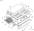
Fig. 1 ] A perspective view illustrating two component mounters of a first embodiment, with a component supply device, upper covers, and a control panel being omitted from one of the two component mounters. - [
Fig. 2 ] An enlarged perspective view illustrating one of the two component mounters inFig. 1 . - [
Fig. 3 ] An enlarged top view illustrating one of the two component mounters inFig. 1 . - [
Fig. 4 ] A cross-sectional view taken along a line IV-IV inFig. 3 . - [
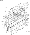
Fig. 5 ] An enlarged perspective view illustrating a component mounter according to a second embodiment. - [
Fig. 6 ] A cross-sectional view, corresponding toFig. 4 , of the component mounter illustrated inFig. 5 . - Hereinafter, an embodiment of a work machine will be described by reference to the drawings. A work machine performs various types of work by moving a head. In this embodiment, the work machine is described as a component mounter. The component mounter is a production device for producing board products by mounting electronic components in predetermined mounting positions on circuit boards. Hereinafter, a "circuit board" will simply be referred to as a "board", and an electronic component will simply be referred to as a "component".
- As illustrated in
Fig. 1 , multiple component mounters 1 are provided to be aligned side by side in, for example, a direction in which boards Bd are conveyed, constituting a production line for producing board products. Each component mounter 1 includesbase 2,board conveyance device 10,component supply device 20, twocomponent transfer devices 30,front column member 60,rear column member 70,frame structure 80,control device 90, and the like. - In the following description, a horizontal width direction of component mounter 1 (a direction directed from an upper left to a lower right in
Fig 1 ) is referred to as an X-axis direction or a left-right direction. A horizontal depth direction of component mounter 1 (a direction directed from a lower left to an upper right inFig. 1 ) is referred to as a Y-axis direction or a front-rear direction. A vertical direction perpendicular to an X-axis and a Y-axis (an up-down direction inFig. 1 ) is referred to as a Z-axis direction or an up-down direction. -
Board conveyance device 10 is placed onbase 2 and is made up of a belt conveyor or the like.Board conveyance device 10 conveys boards Bd sequentially in a conveyance direction (in an X-axis direction in this embodiment).Board conveyance device 10 locates board Bd in a predetermined position inside component mounter 1. Then, after component mounter 1 has performed a mounting process on board Bd,board conveyance device 10 conveys board Bd so processed outside of component mounter 1. -
Component supply device 20 is placed onbase 2 and supplies components to be mounted on boards Bd.Component supply device 20 includesmultiple feeders 21 that are set individually in multiple slots disposed side by side in the X-axis direction in a replaceable fashion. A carrier tape installing with a number of components is wound aroundsupply reel 22 and is loaded in eachfeeder 21. -
Feeder 21 feeds out the carrier tape to supply a component to a supply position located at a distal end offeeder 21 so that the component can be picked up there. - Each of two
component transfer devices 30 is used for a mounting process of picking up a component supplied bycomponent supply device 20 and then mounting the component on board Bd. In this embodiment, twocomponent transfer devices 30 are disposed to be aligned side by side in the left-right direction of component mounter 1 and are supported byframe structure 80. The detailed configuration of twocomponent transfer devices 30 will be described later. - As illustrated in
Fig. 2 ,front column member 60 includes pair offront columns 61 and connectingmember 62. Pair offront columns 61 are provided at left and right sides of a front portion ofbase 2. In this embodiment, pair offront columns 61 are connected together at front end portions by connectingmember 62 extending in a left-right direction ofbase 2 to form an integral portal-like structure. -
Rear column member 70 is disposed separated fromfront column member 60 in the front-rear direction ofbase 2.Rear column member 70 includes pair ofrear columns 71 and a connectingmember 72. Pair ofrear columns 71 are provided at left and right sides of a rear portion ofbase 2. In this embodiment, pair ofrear columns 71 are connected together by connectingmember 72 extending in the left-right direction ofbase 2 to form an integral portal-like structure. -
Frame structure 80 spans pair offront columns 61 and pair ofrear columns 71.Frame structure 80 is a strength member configured not only to support twocomponent transfer devices 30 but also to connectfront column member 60 andrear column member 70 together to thereby improve the overall rigidity of the work machine. A detailed configuration offrame structure 80 will be described later. -
Control device 90 is made up mainly of CPU, various memories, and a control circuit.Control device 90 executes a mounting process of mounting components on boards Bd. The mounting process is executed based on a control program and constitutes a pick and place cycle of picking up a component supplied bycomponent supply device 20 and transferring the component to a predetermined mounting position on board Bd repeatedly multiple times. - In addition, in the mounting process, when controlling the operation of mounting
heads 35, which will be described later,control device 90 receives information outputted from various sensors provided in component mounter 1, and the result of a recognition process by image processing or the like. Then, the control device sends control signals tocomponent transfer devices 30 based on the control program, information from the various sensors, and the results of the various recognition processes. As a result, positions and angles of components held by mountingheads 35 are controlled. - To improve further the accuracy of the mounting process,
control device 90 suppresses and controls vibrations generated in association with the operation of mountingheads 35. For example, when moving mountinghead 35 to a position above a mounting position while executing the mounting process,control device 90 calculates the time it takes until the amplitude of vibration generated in association with the movement of mountinghead 35 is dampened to be equal to or less than an allowable value based on a starting position and an ending position of the movement of mountinghead 35, a traveling speed of mountinghead 35, a mass of the moving member, and the like. Then, after having waited for the calculated dampening time to elapse,control device 90 lowerssuction nozzle 36 holding a component and mounts the component in a predetermined mounting position on board Bd. An improvement in the accuracy of the mounting process is achieved by executing the mounting process while controlling the vibration in the way described above. - Additionally, since vibrations generated during execution of a mounting process by component mounter 1 generate a waiting time corresponding to a dampening time, the vibrations constitute a cause that extends the cycle time necessary for the mounting process. Here, the frequency of vibrations generated in component mounter 1 tends to increase as the rigidities of the constituent members thereof increase, and the dampening time decreases as the frequency increases. By increasing the rigidities of the constituent members of component mounter 1, a waiting time attributed to vibrations generated in a mounting process can be expected to be shortened. Therefore, in component mounter 1, it is desirable that
frame structure 80 is highly rigid,frame structure 80 being a frame structure connectingfront column member 60 andrear column member 70 provided onbase 2 and supporting twocomponent transfer devices 30. - As illustrated in
Fig. 2 ,component transfer device 30 includes Y-axis guide device 31,linear motor 32,X-axis guide device 33, and mountinghead 35. Y-axis guide device 31moves mounting head 35 in a front-rear direction (a Y-axis direction) ofbase 2. Y-axis guide device 31 includes pair ofguide rails 311, fourguide blocks 312, and Y-axis moving body 313. Pair ofguide rails 311 is made up ofleft rail 311L andright rail 311R that both extend in the front-rear direction ofbase 2 and are disposed parallel to each other. - Four guide blocks 312 are each in slidable engagement with pair of guide rails 311. Y-
axis moving body 313 is fixed to lower portions of four guide blocks 312. As a result, Y-axis moving body 313 can move in the front-rear direction ofbase 2 while being suspended fromleft rail 311L andright rail 311R. As described above, Y-axis guide device 31 is of a suspension type in which Y-axis moving body 313 is supported while being suspended from pair ofguide rails 311, allowing a large movable range to be ensured in a left-right direction. -
Linear motor 32 includesmotor shaft 321,motor block 322, andcooling device 323.Motor shaft 321 is a fixed member that is disposed parallel to pair ofguide rails 311 in a space defined in the Y-axis direction between pair of guide rails 311. Multiple ring-like permanent magnets are disposed onmotor shaft 321 along an axial direction. The multiple permanent magnets are disposed in such a manner that magnetic poles of two adjacent magnets differ from each other. -
Motor block 322 is a movable device that is disposed onmotor shaft 321 so as to slide overmotor shaft 321 in a direction in whichmotor shaft 321 extends.Motor block 322 include multiple inductors that are disposed along the extending direction ofmotor shaft 321.Cooling device 323 is made up of a heat conductive pipe, a fan, and the like, all of which are not illustrated.Cooling device 323 dissipates heat generated as a result of driving oflinear motor 32 to an exterior portion to thereby coollinear motor 32. - Y-
axis moving body 313 of Y-axis guide device 31 is fixed to a lower portion ofmotor block 322 oflinear motor 32.Linear motor 32 generates a thrust by feeding the inductors ofmotor block 322.Linear motor 32 moves Y-axis moving body 313 fixed to motor block 322 to a predetermined position in the Y-axis direction by controlling the feeding of the inductors. -
X-axis guide device 33moves mounting head 35 in a left-right direction (an X-axis direction) ofbase 2.X-axis guide device 33 includesX-axis rail 331 andX-axis moving body 332.X-axis rail 331 is disposed on Y-axis moving body 313 in such a manner as to extend in the X-axis direction. X-axis movingbody 332 is in slidable engagement withX-axis rail 331. X-axis movingbody 332 is moved to a predetermined position in the X-axis direction by a drive device, not illustrated. To the drive device, for example, a ball screw device or a linear motor can be applied. - Mounting
head 35 is fixed toX-axis moving body 332 by a clamp, not illustrated. Mountinghead 35 includesmultiple suction nozzles 36 that are provided detachably. Mountinghead 35 supportssuction nozzles 36 individually in such a manner as to be revolved around an R axis parallel to a Z axis and lifted up and down. The lifting and lowering position and angle of eachsuction nozzle 36 relative to mountinghead 35, along with the supply of negative pressure, are controlled. When supplied with negative pressure, eachsuction nozzle 36 picks up through suction a component supplied byfeeder 21 ofcomponent supply device 20. - Two
component transfer devices 30 that are configured in the way described above are disposed to be aligned side by side in the X-axis direction and are allowed to operate independently of each other. Specifically, as illustrated inFigs. 3 and4 , respective mounting heads 35 of twocomponent transfer devices 30 individually mount components on boards Bd in corresponding movable ranges Rm1, Rm2 that are defined abovebase 2 so as not to overlap each other. Here, movable ranges Rm1, Rm2 are ranges determined by a mechanical configuration of Y-axis guide device 31 andX-axis guide device 33 and are defined as a range that encircles mountinghead 35 when moving mountinghead 35 to both left and right ends and both front and rear ends.Figs. 3 and4 illustrate respective movable ranges Rm1, Rm2 of twocomponent transfer devices 30 in the X-axis direction. - Hereinafter, for the sake of simplifying the description, as denoted by parenthesized reference numerals in
Fig. 2 , of twocomponent transfer devices 30, incomponent transfer device 35 on a left side (an upstream side in a conveyance direction of board Bd), Y-axis guide device 31 is also referred to asfirst guide device 40,linear motor 32 asfirst drive device 45, and mountinghead 35 asfirst head 46.Left rail 311L andright rail 311R that constitute pair ofguide rails 311 offirst guide device 40 are also referred to as firstleft rail 41 and firstright rail 42, respectively. - Further, of two
component transfer devices 30, incomponent transfer device 35 on a right side (a downstream side in the conveyance direction of board Bd), Y-axis guide device 31 is also referred to assecond guide device 50,linear motor 32 assecond drive device 55, and mountinghead 35 assecond head 56.Left rail 311L andright rail 311R that constitute pair ofguide rails 311 ofsecond guide device 50 are also referred to as secondleft rail 51 and secondright rail 52, respectively. - In this embodiment,
frame structure 80 is fixed tofront column member 60 andrear column member 70, which each have an integral portal-like structure, while spanning these column members. In this embodiment, as illustrated inFig. 3 ,frame structure 80 has a rectangular shape that surrounds an outer circumference of component mounter 1 when viewed from above.Frame structure 80 has a box-like shape that is opened downwards and upwards to thereby ensure structural rigidity thereof. - As illustrated in
Fig. 3 ,frame structure 80 includes leftframe 81,right frame 82,center frame 83,front frame 84,rear frame 85, and the like.Left frame 81 extends in the front-rear direction (the Y-axis direction) ofbase 2 and spans a space defined between a left end portion offront column 60 and a left end portion ofrear column member 70. As illustrated inFig. 4 , inleft frame 81, the external shape of a cross section at right angles to the Y-axis direction extends in an up-down direction. First leftrail 41 offirst guide device 40 is provided at a lower portion ofleft frame 81. -
Right frame 82 is axially symmetric withleft frame 81 with respect to the center ofbase 2 in the left-right direction thereof as a center line. As illustrated inFig. 3 ,right frame 82 extends in the front-rear direction (the Y-axis direction) ofbase 2 and spans a space defined between a right end portion offront column member 60 and a right end portion ofrear column member 70. As illustrated inFig. 4 , inright frame 82, the external shape of a cross section at right angles to the Y-axis direction extends in the up-down direction. Secondright rail 52 ofsecond guide device 50 is provided at a lower portion ofright frame 82. - As illustrated in
Fig. 3 ,center frame 83 is disposed betweenleft frame 81 andright frame 82 in the X-axis direction.Center frame 83 extends in the Y-axis direction and spans a space defined between a center portion offront column member 60 and a center portion ofrear column member 70. As illustrated inFig. 4 , incenter frame 83, the external shape of a cross section at right angles to the Y-axis direction has a rectangular shape that extends in the up-down direction. Firstright rail 42 offirst guide device 40 and secondleft rail 51 ofsecond guide device 50 are provided at a lower portion ofcenter frame 83. - As illustrated in
Fig. 3 ,front frame 84 andrear frame 85 extend in the X-axis direction, and in each offront frame 84 andrear frame 85, the external shape of a cross section at right angles to the X-axis direction extends in the up-down direction.Front frame 84 connects respective upper portions of pair offront columns 61 together and also connects respective front end portions ofleft frame 81,right frame 82, andcenter frame 83 together.Rear frame 85 connects respective upper portions of pair ofrear columns 71 and also connects respective rear ends ofleft frame 81,right frame 82, andcenter frame 83 together. - Here, in this embodiment, pair of
front columns 61 are connected together by connectingmember 62 to thereby formfront column member 60, which has an integral portal-like structure. In this embodiment, pair ofrear columns 71 are connected together by connectingmember 72 to thereby formrear column member 70, which has an integral portal-like structure. With this configuration, the rigidity ofbase 2 in the left-right direction thereof can be further increased. Further, the overall rigidity of component mounter 1 is increased as a result of connectingfront column member 60 andrear column member 70 being connected together byframe structure 80, thereby making it possible to reduce further a risk of generating vibrations. - In this embodiment, an outer frame of
frame structure 80 connects together leftframe 81,right frame 82,front frame 84, andrear frame 85 each having almost the same width in the up-down direction. Inframe structure 80,center frame 83 is disposed betweenleft frame 81 andright frame 82, fabricating a structure that increases the rigidity further. The cross sections offrames 81 to 86 are elongated in the up-down direction increasing the modulus of sectional shape, thereby increasing the bending rigidity offrame structure 80. As a result, frequencies in the X-axis direction and the Y-axis direction of vibrations generated in association with movement offirst head 46 andsecond head 56 can be increased. - In this embodiment,
frame structure 80 ensures the rigidity in the X-axis direction required for frame structure 80 (for example, the rigidity with which a frequency of vibration in the X-axis direction that is generated by a specified operation of mountinghead 35 reaches a threshold value or greater) withfront frame 84 andrear frame 85. As a result,frame structure 80 includes no other member configured to connectleft frame 81 andright frame 82 together other thanfront frame 84 andrear frame 85. As a result, a reduction in weight offrame structure 80 as well as a reduction in production cost and installation cost offrame structure 80 is achieved. - As a result of adopting the configuration described above,
frame structure 80 has the box-like shape that is opened in the up-down direction and ensures a space for installingfirst drive device 45 betweenleft frame 81 andcenter frame 83 and a space for installingsecond drive device 55 betweenright frame 82 andcenter frame 83. Specifically,first drive device 45 is disposed betweenleft frame 81 andcenter frame 83 in the X-axis direction and is supported at both end portions in the front-rear direction ofbase 2 byfront frame 84 andrear frame 85. Similarly,second drive device 55 is disposed betweenright frame 82 andcenter frame 83 in the X-axis direction and is supported at both end portions in the front-rear direction ofbase 2 thereof byfront frame 84 andrear frame 85. - Specifically, as illustrated in
Fig. 3 ,first drive device 45 andsecond drive device 55, which are bothlinear motors 32, are supported at both end portions ofmotor shafts 321 thereof in the Y-axis direction byfront frame 84 andrear frame 85. Then,first drive device 45 applies a driving force for movingfirst head 46 in the front-rear direction ofbase 2 to first movingbody 43. Similarly,second drive device 55 applies a driving force for movingsecond head 56 in the front-rear direction ofbase 2 to second movingbody 53. - As described above, first
left rail 41 offirst guide device 40 is provided at the lower portion ofleft frame 81. In this embodiment, as illustrated inFig. 4 , firstleft rail 41 is disposed within a range where movable range Rm1 offirst head 46 overlaps support range Rs in the left-right direction ofbase 2 where pair offront columns 61 and pair ofrear columns 71 are connected to framestructure 80. InFig. 4 , inner end faces of leftfront column 61 and leftrear column 71 are indicated by broken lines. - Second
right rail 52 ofsecond guide device 50 is provided at the lower portion ofright frame 82. In this embodiment, as illustrated inFig. 4 , secondright rail 52 is disposed within a range where movable range Rm2 ofsecond head 56 overlaps support range Rs in the left-right direction ofbase 2 where pair offront columns 61 and pair ofrear columns 71 are connected to framestructure 80. InFig. 4 , inner end faces of rightfront column 61 and rightrear column 71 are indicated by broken lines. - Here, support ranges Rs are ranges in the X-axis direction where
frame structure 80 connects tofront column member 60 andrear column member 70. Support ranges Rs correspond to ranges represented by a range in the X-axis direction whereleft frame 81 is supported directly or indirectly by one of the pair offront columns 61 and one of the pair ofrear columns 71 and a range in the X-axis direction whereright frame 82 is supported directly or indirectly by the other of the pairfront columns 61 and the other of the pair ofrear columns 71. - With such a configuration, a downward load exerted to left
frame 81 from firstleft rail 41 is generally transmitted to leftfront column 61 and leftrear column 71 that reside in support range Rs as a buckling load. Similarly, a downward load exerted toright frame 82 from secondright rail 52 is generally transmitted toright front column 61 and rightrear column 71 that reside in support range Rs as a buckling load. - As a result of the transmission of the loads in this way,
first guide device 40 andsecond guide device 50, which generate vibrations as movement occurs, are supported with the buckling strengths offront column member 60 andrear column member 70 viaframe structure 80. As a result, the overall structural rigidity of component mounter 1 is increased, thereby not only suppressing the generation of vibrations but also increasing the frequency of generated vibrations. - First
right rail 42 offirst guide device 40 and secondleft rail 51 ofsecond guide device 50 are provided at the lower portion ofcenter frame 83. In this embodiment, as illustrated inFig. 4 , firstright rail 42 is disposed inside movable range Rm1 offirst head 46 in the X-axis direction. Similarly, secondleft rail 51 is disposed inside movable range Rm2 ofsecond head 56 in the X-axis direction. - Here, as illustrated in
Fig. 2 , pair offront columns 61 and pair ofrear columns 71 both haveside surfaces base 2, constituting the same flat plane. This configuration is designed to enable installation of component mounter 1 as close to another adjacent component mounter 1 as possible as illustrated inFig. 1 when a production line including component mounters 1 is configured. As a result, the production line including component mounters 1 can be shortened to thereby improve the productivity per unit area in an assembling facility. - Further, as illustrated in
Fig. 1 , pair of left and right connectingplates 89 are disposed onside surfaces 611 of pair offront columns 61 andside surfaces 711 of pair ofrear columns 71 to connect side surfaces (611, 711) together. As a result of adopting this configuration, component mounter 1 increases its overall rigidity in the front-rear direction by making use of the tensile strength of connectingplates 89. Consequently, this configuration increases particularly the rigidity in the Y-axis direction, increasing the frequency in the Y-axis direction of vibrations generated asfirst head 46 andsecond head 56 move. - 1-4. Advantageous Effects of Configuration of First Embodiment With the configuration of component mounter 1 described above, pair of
front columns 61 and pair ofrear columns 71 are connected together byframe structure 80. As a result, the overall rigidity of component mounter 1 is improved by the structural rigidity offrame structure 80 while maintaining the overall external dimensions of component mounter 1. Thus, the frequency of vibrations generated asfirst head 46 andsecond head 56 move can be increased. As a result of increasing the frequency of the vibrations, suppressing and controlling the vibrations comes to be facilitated, which means an improvement in mounting accuracy is achieved by reducing the effect of the vibrations. - Additionally, in
frame structure 80,first guide device 40 andsecond guide device 50, which are suspended, are supported by providing individual rails (41, 42, 51, 52) at the lower portions ofleft frame 81,right frame 82, andcenter frame 83. As a result of adopting this configuration, component mounter 1 reliably bears the loads offirst guide device 40 andsecond guide device 50 withbase 2,front column member 60,rear column member 70, andframe structure 80, making it possible to suppress the occurrence of vibrations that would otherwise be caused asfirst head 46 andsecond head 56 move. - A work machine (component mounter 101) of a second embodiment differs from component mounter 1 of the first embodiment mainly in the configuration of
frame structure 80. Since other common configurations are substantially the same as those of the first embodiment, detailed descriptions thereof will be omitted. Specifically, as illustrated inFig. 5 ,component mounter 101 includesbase 102,board conveyance device 10, component supply device 20 (omitted inFig. 5 ), one component transfer device 30 (first guide device 140),front column member 160,rear column member 170, frame structure 180,control device 90, and the like. - In contrast to the configuration of component mounter 1 of the first embodiment in which two
component transfer devices 30 are provided,component mounter 101 of this embodiment has only onecomponent transfer device 30. Due to this, compared with component mounter 1 of the first embodiment, widths in an X-axis direction ofcomponent mounter 101 andbase 102 are generally half of those of component mounter 1.Component transfer device 30 of this embodiment is of the same type as twocomponent transfer devices 30 of the first embodiment and includesfirst guide device 140,first drive device 145,first head 146, and the like. -
Front column member 160 has an integral portal-like structure, which has pair offront columns 61, provided at left and right sides of a front portion ofbase 102, connected by connectingmember 162 extending in the X-axis direction. Similarly,rear column member 170 has an integral portal-like structure, which has pair ofrear columns 71 provided at left and right sides of a rear portion ofbase 102 connected by connectingmember 172 extending in the X-axis direction. - Frame structure 180 is a strength member that supports one
component transfer device 30 and improves the overall rigidity ofcomponent mounter 101 by connectingfront column member 160 andrear column member 170 together. Frame structure 180 has a similar configuration to the configuration offrame structure 80 of the first embodiment except thatcenter frame 83 is removed from or is not provided on frame structure 180 and includes leftframe 81,right frame 82,front frame 84,rear frame 85, and the like. - As illustrated in
Fig. 6 , firstleft rail 41 offirst guide device 140 is provided at a lower portion ofleft frame 81. Firstright rail 42 offirst guide device 140 is provided at a lower portion ofright frame 82. As in the first embodiment,front frame 84 connects pair offront columns 61 together and also connects respective front ends ofleft frame 81 andright frame 82 together.Rear frame 85 connects pair ofrear columns 71 together and also connects respective rear ends ofleft frame 81 andright frame 82. - As illustrated in
Fig. 6 , firstleft rail 41 and firstright rail 42 offirst guide device 140 are disposed within ranges where movable range Rm1 offirst head 46 overlaps support ranges Rs in a left-right direction ofbase 102 where pair of firstfront columns 61 and pair ofrear columns 71 are connected to frame structure 180. InFig. 6 , inner end faces pair offront columns 61 and pair ofrear columns 71 are indicated by broken lines. -
First drive device 145 is disposed betweenleft frame 81 andright frame 82. As illustrated inFig. 5 ,first drive device 145 is supported at both end portions in the front-rear direction ofbase 102 byfront frame 84 andrear frame 85. Specifically,first drive device 145, which is alinear motor 32, is supported at both end portions ofmotor shaft 321 in a Y-axis direction byfront frame 84 andrear frame 85.First drive device 145 applies a driving force, to first movingbody 43, for movingfirst head 146 in the front-rear direction ofbase 102. - As a result of adopting this configuration, as in the configuration of the first embodiment, a downward load exerted to frame structure 180 from
first guide device 140 is generally transmitted to pair offront columns 61 and pair ofrear columns 71 that both reside in support ranges Rs as a buckling load. As a result,first guide device 140, which can generate vibrations as it operates, is supported with the bucking strengths offront column member 160 andrear column member 170 via frame structure 180. As a result, incomponent mounter 101, not only is the generation of vibrations suppressed by increasing the overall structural rigidity ofcomponent mounter 101, but also the frequency of generated vibrations is increased. - With the configuration of
component mounter 101 described above, pair offront columns 61 and pair ofrear columns 71 are connected together by frame structure 180. As a result, incomponent mounter 101, the overall rigidity thereof is improved by the structural rigidity of frame structure 180 while maintaining the overall external dimensions ofcomponent mounter 101. Thus, the frequency of vibrations generated asfirst head 146 moves can be increased. As a result, suppression and control of the vibrations are facilitated, thereby reducing the effect of the vibrations and improving working accuracy. - In frame structure 180,
first guide device 140, which is suspended, is supported by providing the individual rails (41, 42) at the lower portions ofleft frame 81 andright frame 82. As a result, incomponent mounter 101, the load offirst guide device 140 can be reliably borne bybase 102,front column member 160,rear column member 170, and frame structure 180, thereby making it possible to suppress the generation of vibrations that would otherwise be caused asfirst head 146 moves. - In the first embodiment and the second embodiment,
frame structures 80, 180 have a box-like shape that is opened downwards and upwards. In contrast to the configuration described above,frame structures 80, 180 may have, for example, a shape that is covered with a plate or a cover member at the upper side thereof. - In addition, in the first embodiment and the second embodiment,
front column members front columns 61 being connected together by connectingmembers front column members members frame structures 80, 180. Similarly,rear column members members frame structures 80, 180. However, from the viewpoint of securing the rigidity and reducing the number of components, the aspects exemplified in the first embodiment and the second embodiment are desirable. - In the first and second embodiments, pair of connecting
plates 89 are individually made to connect the respective side surfaces (611, 711) of pair offront columns 61 and pair ofrear columns 71 together. In contrast to the configuration described above, inframe structures 80, 180, side surfaces 801 on both the sides in the X-axis direction may both constitute the same planar shape as the side surfaces (611, 711), and pair offront columns 61 and pair ofrear columns 71 may be connected together by pair of connectingplates 89. - With this configuration, in
component mounters 1, 101, the overall rigidity in the front-rear direction can be increased further by the tensile strength of pair of connectingplates 89. As a result, since the frequency of vibrations in the front-rear direction generated as mountinghead 35 moves can be increased, the suppression and control of the vibrations is facilitated, thereby reducing the effect of the vibrations and improving mounting accuracy. Further, connectingplates 89 may be made to connect the side surfaces ofbases - In the first and second embodiments,
first drive devices second drive device 55 are each described as beinglinear motor 32. In contrast to the configuration described above, a linear motion device such as a ball screw device may be applied tofirst drive devices second drive device 55, as long as the linear motion device can apply, to first movingbody 43 and second movingbody 53, a driving force for movingfirst heads second head 56 in the front-rear direction (the Y-axis direction) ofbases first drive devices second drive device 55 are each made up of a ball screw device, both end portions of a threaded shaft are supported byfront frame 84 andrear frame 85. - In the first embodiment and the second embodiment, the work machine is described as forming
component mounters 1, 101 for producing board products. In contrast to the configuration described above, the work machine may be of various types of work machines other than the component mounter, as long as such work machines are limited by the appended claims and such that various types of work are performed by moving the head. Specifically, the work machine may be a solder printer that constitutes a production line together withcomponent mounters 1, 101 or an inspection device configured to inspect circuit boards on which components are mounted. -
- 1,101: Component mounter;
- 2, 102: Base;
- 10: Board conveyance device;
- 20: Component supply device;
- 30: Component transfer device;
- 31 (40, 50, 140): Y-axis guide device (first guide device, second guide device),
- 311 : Guide rail;
- 311L (41, 51): Left rail (first left rail, second left rail);
- 311R (42, 52): Right rail (first right rail, second right rail);
- 312: Guide block;
- 313(43, 53): Y-axis moving body (first moving body, second moving body);
- 32(45, 55, 145): Linear motor (first driving device, second driving device);
- 35(46, 56, 146): Mounting head (first head, second head);
- 60, 160: Front column member;
- 61: (Pair of) Front columns;
- 611: Side surface;
- 62, 162: Connecting member;
- 70, 170: Rear column;
- 71: (Pair of) Rear columns;
- 711: Side surface;
- 72, 172: Connecting member;
- 80, 180: Frame structure;
- 81: Left frame;
- 82: Right frame;
- 83: Center frame;
- 84: Front frame;
- 85: Rear frame;
- 801: Side surface;
- 89: (Pair of) Connecting plates;
- Rm1: Movable range (of first mounting head);
- Rm2: Movable range (of second mounting head);
- Rs: Support range;
- Bd: Board (Circuit board)
Claims (14)
- A work machine (1) comprising:a base (2);a pair of front columns (61) provided on left and right sides of a front portion of the base (2);a pair of rear columns (71) provided on left and right sides of a rear portion of the base (2);a frame structure (80) spanning the pair of front columns (61) and the pair of rear columns (71);a first head and a second head (46,56) both configured to perform predetermined work in movable ranges (Rm1,Rm2) defined so as not to overlap each other above the base;a first guide device (40) provided on the frame structure (80) on a left side of the center of the base (2) in a left-right direction thereof and configured to allow the first head (46) to move in a front-rear direction of the base (2), anda second guide device (50) provided on the frame structure on a right side of the center of the base (2) in the left-right direction thereof and configured to allow the second head (56) to move in the front-rear direction of the base (2);wherein the first guide device (40) further comprises:a first left rail (41) and a first right rail (42) both extending in the front-rear direction of the base (2), the first left rail (41) and the first right rail (42) being parallel, anda first moving body (43) provided so as to move in the front-rear direction of the base (2) while being suspended from the first left rail (41) and the first right rail (42) and supporting the first head (46);wherein the second guide device (50) further comprises:a second left rail (51) and a second right rail (52) both extending in the front-rear direction of the base (2), the second left rail (51) and the second right rail (52) being parallel, anda second moving body (53) provided so as to move in the front-rear direction of the base (2) while being suspended from the second left rail (51) and the second right rail (52) and supporting the second head (56);wherein the frame structure (80) further comprises:a left frame (81) in which the first left rail (41) of the first guide device (40) is provided at a lower portion thereof;a right frame (82) in which the second right rail (52) of the second guide device (50) is provided at a lower portion thereof;a center frame (83), being disposed between the left frame (81) and the right frame (82), in which the first right rail (42) of the first guide device (40)) and the second left rail (51) of the second guide device (50) are provided at a lower portion thereof;a front frame (84) connecting the pair of front columns (61) together and also connecting respective front ends of the left frame (81), the right frame (82), and the center frame (83) together, anda rear frame (85) connecting the pair of rear columns (71) together and also connecting respective rear ends of the left frame (81), the right frame (82), and the center frame (83) together,characterized in thatthe frame structure (80) has a rectangular shape that surrounds an outer circumference of component mounter (1) when viewed from above, andthe frame structure (80) has a box-like shape that is opened downwards and upwards to thereby ensure structural rigidity thereof.
- The work machine (1) according to claim 1,wherein the first left rail (41) of the first guide device (40) is disposed within a range where the movable range (Rm1) of the first head (46) overlaps a support range (Rs) in a left-right direction of the base (2) where the pair of front columns (61) and the pair of rear columns (71) are connected to the frame structure (80), andwherein the second right rail (52) of the second guide device (50) is disposed within a range where the movable range (Rm2) of the second head (56) overlaps a support range (Rs) in the left-right direction of the base (2) where the pair of front columns (61) and the pair of rear columns (71) are connected to the frame structure (80).
- The work machine (1) according to claim 1 or 2, wherein an external shape of a cross section of the center frame (83) that is at right angles to the front-rear direction of the base (2) has a rectangular shape that is elongated in an up-down direction.
- The work machine (1) according to any one of claims 1 to 3, wherein the work machine (1) further comprises:a first drive device (45) disposed between the left frame (81) and the center frame (83), supported at both end portions in the front-rear direction of the base (2) thereof by the front frame (84) and the rear frame (85), and configured to apply a driving force, to the first moving body (43), for moving the first head (46) in the front-rear direction of the base (2); anda second drive device (55) provided between the right frame (82) and the center frame (83, supported at both end portions in the front-rear direction of the base (2) thereof by the front frame (84) and the rear frame (85), and configured to apply a driving force, to the second moving body (53), for moving the second head (56) in the front-rear direction of the base (2).
- A work machine (101) comprising:a base (102);a pair of front columns (61) provided on left and right sides of a front portion of the base (102);a pair of rear columns (71) provided on left and right sides of a rear portion of the base (102);a frame structure (180) spanning the pair of front columns (61) and the pair of rear columns (71);a first head (146) configured to perform predetermined work in a movable range (Rm1) defined above the base (2), anda first guide device (140) provided on the frame structure (180) and configured to allow the first head (146) to move in a front-rear direction of the base (102);wherein the first guide device (140) further comprises:a first left rail (41) and a first right rail (42) both extending in the front-rear direction of the base (102), the first left rail (41) and the first right rail (42) being parallel, anda first moving body (43), being provided so as to move in the front-rear direction of the base (102), while being suspended from the first left rail (41) and the first right rail (42), and supporting the first head (146);wherein the frame structure (180) further comprises:a left frame (81) in which the first left rail (41) of the first guide device (140) is provided at a lower portion thereof;a right frame (82) in which the first right rail (42) of the first guide device (140) is provided at a lower portion thereof;a front frame (84) connecting the pair of front columns (61) together and also connecting respective front ends of the left frame (81) and the right frame (82) together, anda rear frame (85) connecting the pair of rear columns (71) together and also connecting respective rear ends of the left frame (81) and the right frame (82) together;wherein the first left rail (41) and the first right rail (42) of the first guide device are disposed respectively in ranges where the movable range (Rm1) of the first head (146) overlaps left and right support ranges (Rs) defined in a left-right direction of the base (102) where the pair of front columns (61) and the pair of rear columns (71) are connected to the frame structure (180),characterized in thatthe frame structure (80) has a rectangular shape that surrounds an outer circumference of component mounter (1) when viewed from above, andthe frame structure (80) has a box-like shape that is opened downwards and upwards to thereby ensure structural rigidity thereof.
- The work machine (101) according to claim 5, wherein the work machine (101) further comprises a first drive device (145) disposed between the left frame (81) and the right frame (82), supported at both end portions in the front-rear direction of the base (102) thereof by the front frame (84) and the rear frame (85), and configured to apply a driving force, to the first moving body (43), for moving the first head (146) in the front-rear direction of the base (102).
- The work machine (1;101) according to any one of claims 1 to 6, wherein the pair of front columns (61), the pair of rear columns (71), and the frame structure (80;180) comprise side surfaces, on both sides in the left-right direction of the base (2;102), each having the same planar shape.
- The work machine (1;101) according to any one of claims 1 to 7, wherein the work machine (1;101) further comprises a pair of left and right connecting plates (89) configured to connect the side surfaces of the pair of front columns (61) and the pair of rear columns together (71).
- The work machine (1;101) of claim 8, wherein the pair of connecting plates (89) connect individually the corresponding side surfaces of the pair of front columns (61), the pair of rear columns (71), and the frame structure (80;180) together.
- The work machine (1;101) according to any one of claims 1 to 9, wherein external shapes of cross sections of the left frame (81) and the right frame (82) that are at right angles to the front-rear direction of the base (2) are elongated in the up-down direction.
- The work machine (1;101) according to claim 10,wherein external shapes of cross sections of the front frame (84) and the rear frame (85) that are at right angles to the front-rear direction of the base (1;102) are elongated in the up-down direction, andwherein the frame structure (80;180) has a box-like shape that is opened at least downwards.
- The work machine (1;101) according to any one of claims 1 to 11, wherein the pair of front columns (61) and the pair of rear columns (71) are each connected together by a connecting member (62;162) extending in the left-right direction of the base (2;102) to thereby constitute an integral portal-like structure.
- The work machine (1;101) according to any one of claims 1 to 12, wherein the frame structure (80;180) has no frame configured to connect the left frame (81) and the right frame (82) together other than the front frame (84) and the rear frame (85).
- The work machine (1; 101) according to any one of claims 1 to 13,wherein the first head (46;146) is a mounting head (35) configured to perform mounting work of mounting an electronic component on a circuit board, andwherein the work machine (1 ;102) is a component mounter configured to produce a board product using the first head (46;146).
Applications Claiming Priority (1)
| Application Number | Priority Date | Filing Date | Title |
|---|---|---|---|
| PCT/JP2017/001414 WO2018134893A1 (en) | 2017-01-17 | 2017-01-17 | Work machine |
Publications (3)
| Publication Number | Publication Date |
|---|---|
| EP3573441A1 EP3573441A1 (en) | 2019-11-27 |
| EP3573441A4 EP3573441A4 (en) | 2020-01-01 |
| EP3573441B1 true EP3573441B1 (en) | 2023-02-22 |
Family
ID=62907933
Family Applications (1)
| Application Number | Title | Priority Date | Filing Date |
|---|---|---|---|
| EP17892443.7A Active EP3573441B1 (en) | 2017-01-17 | 2017-01-17 | Work machine |
Country Status (5)
| Country | Link |
|---|---|
| US (1) | US11134596B2 (en) |
| EP (1) | EP3573441B1 (en) |
| JP (1) | JP6761485B2 (en) |
| CN (1) | CN110199586B (en) |
| WO (1) | WO2018134893A1 (en) |
Families Citing this family (3)
| Publication number | Priority date | Publication date | Assignee | Title |
|---|---|---|---|---|
| CN110282341A (en) * | 2019-06-25 | 2019-09-27 | 英业达科技有限公司 | Fetching device |
| JP7310500B2 (en) * | 2019-09-27 | 2023-07-19 | ブラザー工業株式会社 | Laser processing equipment |
| CN111642126B (en) * | 2020-05-25 | 2021-04-09 | 深圳市琦轩实创科技有限公司 | A paster equipment for production of electron class product |
Family Cites Families (12)
| Publication number | Priority date | Publication date | Assignee | Title |
|---|---|---|---|---|
| JPH09150330A (en) * | 1995-11-27 | 1997-06-10 | Sony Corp | Head mounting part moving mechanism in robot for surface mounting machine |
| JP3255062B2 (en) * | 1997-01-17 | 2002-02-12 | 松下電器産業株式会社 | Electronic component mounting device |
| JP3954210B2 (en) * | 1998-08-20 | 2007-08-08 | ヤマハ発動機株式会社 | Control device for linear drive mechanism |
| EP1059021B1 (en) * | 1998-12-29 | 2005-03-09 | Assembléon N.V. | Component placement machine |
| US6976304B2 (en) * | 2001-07-27 | 2005-12-20 | Matsushita Electric Industrial Co., Ltd. | Components placing apparatus |
| JP2004241595A (en) | 2003-02-06 | 2004-08-26 | Matsushita Electric Ind Co Ltd | Component mounting machine |
| JP4316325B2 (en) * | 2003-08-12 | 2009-08-19 | パナソニック株式会社 | Component mounter mount and component mounter |
| JP5053926B2 (en) * | 2008-05-09 | 2012-10-24 | ヤマハ発動機株式会社 | Substrate processing equipment |
| JP5525956B2 (en) | 2010-07-30 | 2014-06-18 | ヤマハ発動機株式会社 | Mounting machine |
| JP5601459B2 (en) | 2010-08-18 | 2014-10-08 | 富士機械製造株式会社 | Electronic circuit component mounting machine and electronic circuit component mounting system |
| JP2015015410A (en) * | 2013-07-08 | 2015-01-22 | パナソニックIpマネジメント株式会社 | Component mounting device |
| JP6272705B2 (en) * | 2014-02-10 | 2018-01-31 | 株式会社クボタ | Working machine |
-
2017
- 2017-01-17 EP EP17892443.7A patent/EP3573441B1/en active Active
- 2017-01-17 US US16/476,136 patent/US11134596B2/en active Active
- 2017-01-17 WO PCT/JP2017/001414 patent/WO2018134893A1/en unknown
- 2017-01-17 JP JP2018562765A patent/JP6761485B2/en active Active
- 2017-01-17 CN CN201780083478.7A patent/CN110199586B/en active Active
Also Published As
| Publication number | Publication date |
|---|---|
| WO2018134893A1 (en) | 2018-07-26 |
| US20190350112A1 (en) | 2019-11-14 |
| EP3573441A1 (en) | 2019-11-27 |
| EP3573441A4 (en) | 2020-01-01 |
| CN110199586A (en) | 2019-09-03 |
| US11134596B2 (en) | 2021-09-28 |
| CN110199586B (en) | 2021-02-12 |
| JP6761485B2 (en) | 2020-09-23 |
| JPWO2018134893A1 (en) | 2019-08-08 |
Similar Documents
| Publication | Publication Date | Title |
|---|---|---|
| EP3573441B1 (en) | Work machine | |
| JP5704944B2 (en) | Substrate working device | |
| KR101663870B1 (en) | Die bonder | |
| US10340163B2 (en) | Mounting apparatus | |
| WO2014045370A1 (en) | Work machine for printed circuit boards and mounting method | |
| WO2015151403A1 (en) | Industrial robot and frame unit thereof | |
| JP4813315B2 (en) | Surface mount machine | |
| KR101282165B1 (en) | Mounting apparatus | |
| JP6325651B2 (en) | Component assembly apparatus and component assembly method | |
| JP4494910B2 (en) | Surface mount equipment | |
| KR102329100B1 (en) | Mounting device and manufacturing method of semiconductor device | |
| KR101181968B1 (en) | Dual Picker Cylinder, and Picking and Transferring Device for Semiconductor parts having the same | |
| JP4316325B2 (en) | Component mounter mount and component mounter | |
| JP7266103B2 (en) | Backup pin automatic placement system for mounters | |
| JP2019063930A (en) | Workpiece transport apparatus | |
| JP4342652B2 (en) | Harness wiring structure in surface mounters | |
| WO2015162751A1 (en) | Optimization program and mounting operation system | |
| WO2022190976A1 (en) | Bonding device and bonding method | |
| JP7266101B2 (en) | Backup pin automatic placement system for mounters | |
| EP3784013A1 (en) | Work machine | |
| JP2021019140A (en) | Substrate work device and manufacturing method of the same | |
| KR20030009680A (en) | Surface Mount Device Having a Lot of Gantries | |
| JP2007251047A (en) | Mounter for surface-mounting component | |
| JP2018113374A (en) | Conveyor support structure and component mounting device | |
| WO2017013696A1 (en) | Component mounting machine |
Legal Events
| Date | Code | Title | Description |
|---|---|---|---|
| STAA | Information on the status of an ep patent application or granted ep patent |
Free format text: STATUS: THE INTERNATIONAL PUBLICATION HAS BEEN MADE |
|
| PUAI | Public reference made under article 153(3) epc to a published international application that has entered the european phase |
Free format text: ORIGINAL CODE: 0009012 |
|
| STAA | Information on the status of an ep patent application or granted ep patent |
Free format text: STATUS: REQUEST FOR EXAMINATION WAS MADE |
|
| 17P | Request for examination filed |
Effective date: 20190716 |
|
| AK | Designated contracting states |
Kind code of ref document: A1 Designated state(s): AL AT BE BG CH CY CZ DE DK EE ES FI FR GB GR HR HU IE IS IT LI LT LU LV MC MK MT NL NO PL PT RO RS SE SI SK SM TR |
|
| AX | Request for extension of the european patent |
Extension state: BA ME |
|
| A4 | Supplementary search report drawn up and despatched |
Effective date: 20191202 |
|
| RIC1 | Information provided on ipc code assigned before grant |
Ipc: B25J 9/02 20060101ALI20191126BHEP Ipc: H05K 13/04 20060101AFI20191126BHEP |
|
| DAV | Request for validation of the european patent (deleted) | ||
| DAX | Request for extension of the european patent (deleted) | ||
| STAA | Information on the status of an ep patent application or granted ep patent |
Free format text: STATUS: EXAMINATION IS IN PROGRESS |
|
| 17Q | First examination report despatched |
Effective date: 20210728 |
|
| STAA | Information on the status of an ep patent application or granted ep patent |
Free format text: STATUS: EXAMINATION IS IN PROGRESS |
|
| GRAP | Despatch of communication of intention to grant a patent |
Free format text: ORIGINAL CODE: EPIDOSNIGR1 |
|
| STAA | Information on the status of an ep patent application or granted ep patent |
Free format text: STATUS: GRANT OF PATENT IS INTENDED |
|
| INTG | Intention to grant announced |
Effective date: 20221111 |
|
| GRAS | Grant fee paid |
Free format text: ORIGINAL CODE: EPIDOSNIGR3 |
|
| GRAA | (expected) grant |
Free format text: ORIGINAL CODE: 0009210 |
|
| STAA | Information on the status of an ep patent application or granted ep patent |
Free format text: STATUS: THE PATENT HAS BEEN GRANTED |
|
| AK | Designated contracting states |
Kind code of ref document: B1 Designated state(s): AL AT BE BG CH CY CZ DE DK EE ES FI FR GB GR HR HU IE IS IT LI LT LU LV MC MK MT NL NO PL PT RO RS SE SI SK SM TR |
|
| REG | Reference to a national code |
Ref country code: GB Ref legal event code: FG4D |
|
| REG | Reference to a national code |
Ref country code: CH Ref legal event code: EP |
|
| REG | Reference to a national code |
Ref country code: AT Ref legal event code: REF Ref document number: 1550358 Country of ref document: AT Kind code of ref document: T Effective date: 20230315 Ref country code: IE Ref legal event code: FG4D |
|
| REG | Reference to a national code |
Ref country code: DE Ref legal event code: R096 Ref document number: 602017066298 Country of ref document: DE |
|
| REG | Reference to a national code |
Ref country code: LT Ref legal event code: MG9D |
|
| P01 | Opt-out of the competence of the unified patent court (upc) registered |
Effective date: 20230328 |
|
| REG | Reference to a national code |
Ref country code: NL Ref legal event code: MP Effective date: 20230222 |
|
| REG | Reference to a national code |
Ref country code: AT Ref legal event code: MK05 Ref document number: 1550358 Country of ref document: AT Kind code of ref document: T Effective date: 20230222 |
|
| PG25 | Lapsed in a contracting state [announced via postgrant information from national office to epo] |
Ref country code: RS Free format text: LAPSE BECAUSE OF FAILURE TO SUBMIT A TRANSLATION OF THE DESCRIPTION OR TO PAY THE FEE WITHIN THE PRESCRIBED TIME-LIMIT Effective date: 20230222 Ref country code: PT Free format text: LAPSE BECAUSE OF FAILURE TO SUBMIT A TRANSLATION OF THE DESCRIPTION OR TO PAY THE FEE WITHIN THE PRESCRIBED TIME-LIMIT Effective date: 20230622 Ref country code: NO Free format text: LAPSE BECAUSE OF FAILURE TO SUBMIT A TRANSLATION OF THE DESCRIPTION OR TO PAY THE FEE WITHIN THE PRESCRIBED TIME-LIMIT Effective date: 20230522 Ref country code: NL Free format text: LAPSE BECAUSE OF FAILURE TO SUBMIT A TRANSLATION OF THE DESCRIPTION OR TO PAY THE FEE WITHIN THE PRESCRIBED TIME-LIMIT Effective date: 20230222 Ref country code: LV Free format text: LAPSE BECAUSE OF FAILURE TO SUBMIT A TRANSLATION OF THE DESCRIPTION OR TO PAY THE FEE WITHIN THE PRESCRIBED TIME-LIMIT Effective date: 20230222 Ref country code: LT Free format text: LAPSE BECAUSE OF FAILURE TO SUBMIT A TRANSLATION OF THE DESCRIPTION OR TO PAY THE FEE WITHIN THE PRESCRIBED TIME-LIMIT Effective date: 20230222 Ref country code: HR Free format text: LAPSE BECAUSE OF FAILURE TO SUBMIT A TRANSLATION OF THE DESCRIPTION OR TO PAY THE FEE WITHIN THE PRESCRIBED TIME-LIMIT Effective date: 20230222 Ref country code: ES Free format text: LAPSE BECAUSE OF FAILURE TO SUBMIT A TRANSLATION OF THE DESCRIPTION OR TO PAY THE FEE WITHIN THE PRESCRIBED TIME-LIMIT Effective date: 20230222 Ref country code: AT Free format text: LAPSE BECAUSE OF FAILURE TO SUBMIT A TRANSLATION OF THE DESCRIPTION OR TO PAY THE FEE WITHIN THE PRESCRIBED TIME-LIMIT Effective date: 20230222 |
|
| PG25 | Lapsed in a contracting state [announced via postgrant information from national office to epo] |
Ref country code: SE Free format text: LAPSE BECAUSE OF FAILURE TO SUBMIT A TRANSLATION OF THE DESCRIPTION OR TO PAY THE FEE WITHIN THE PRESCRIBED TIME-LIMIT Effective date: 20230222 Ref country code: PL Free format text: LAPSE BECAUSE OF FAILURE TO SUBMIT A TRANSLATION OF THE DESCRIPTION OR TO PAY THE FEE WITHIN THE PRESCRIBED TIME-LIMIT Effective date: 20230222 Ref country code: IS Free format text: LAPSE BECAUSE OF FAILURE TO SUBMIT A TRANSLATION OF THE DESCRIPTION OR TO PAY THE FEE WITHIN THE PRESCRIBED TIME-LIMIT Effective date: 20230622 Ref country code: GR Free format text: LAPSE BECAUSE OF FAILURE TO SUBMIT A TRANSLATION OF THE DESCRIPTION OR TO PAY THE FEE WITHIN THE PRESCRIBED TIME-LIMIT Effective date: 20230523 Ref country code: FI Free format text: LAPSE BECAUSE OF FAILURE TO SUBMIT A TRANSLATION OF THE DESCRIPTION OR TO PAY THE FEE WITHIN THE PRESCRIBED TIME-LIMIT Effective date: 20230222 |
|
| PG25 | Lapsed in a contracting state [announced via postgrant information from national office to epo] |
Ref country code: SM Free format text: LAPSE BECAUSE OF FAILURE TO SUBMIT A TRANSLATION OF THE DESCRIPTION OR TO PAY THE FEE WITHIN THE PRESCRIBED TIME-LIMIT Effective date: 20230222 Ref country code: RO Free format text: LAPSE BECAUSE OF FAILURE TO SUBMIT A TRANSLATION OF THE DESCRIPTION OR TO PAY THE FEE WITHIN THE PRESCRIBED TIME-LIMIT Effective date: 20230222 Ref country code: EE Free format text: LAPSE BECAUSE OF FAILURE TO SUBMIT A TRANSLATION OF THE DESCRIPTION OR TO PAY THE FEE WITHIN THE PRESCRIBED TIME-LIMIT Effective date: 20230222 Ref country code: DK Free format text: LAPSE BECAUSE OF FAILURE TO SUBMIT A TRANSLATION OF THE DESCRIPTION OR TO PAY THE FEE WITHIN THE PRESCRIBED TIME-LIMIT Effective date: 20230222 Ref country code: CZ Free format text: LAPSE BECAUSE OF FAILURE TO SUBMIT A TRANSLATION OF THE DESCRIPTION OR TO PAY THE FEE WITHIN THE PRESCRIBED TIME-LIMIT Effective date: 20230222 |
|
| REG | Reference to a national code |
Ref country code: DE Ref legal event code: R097 Ref document number: 602017066298 Country of ref document: DE |
|
| PG25 | Lapsed in a contracting state [announced via postgrant information from national office to epo] |
Ref country code: SK Free format text: LAPSE BECAUSE OF FAILURE TO SUBMIT A TRANSLATION OF THE DESCRIPTION OR TO PAY THE FEE WITHIN THE PRESCRIBED TIME-LIMIT Effective date: 20230222 |
|
| PLBE | No opposition filed within time limit |
Free format text: ORIGINAL CODE: 0009261 |
|
| STAA | Information on the status of an ep patent application or granted ep patent |
Free format text: STATUS: NO OPPOSITION FILED WITHIN TIME LIMIT |
|
| 26N | No opposition filed |
Effective date: 20231123 |
|
| PG25 | Lapsed in a contracting state [announced via postgrant information from national office to epo] |
Ref country code: SI Free format text: LAPSE BECAUSE OF FAILURE TO SUBMIT A TRANSLATION OF THE DESCRIPTION OR TO PAY THE FEE WITHIN THE PRESCRIBED TIME-LIMIT Effective date: 20230222 |