EP3572284A1 - Fahrzeugumgebungsanzeigevorrichtung - Google Patents
Fahrzeugumgebungsanzeigevorrichtung Download PDFInfo
- Publication number
- EP3572284A1 EP3572284A1 EP19174722.9A EP19174722A EP3572284A1 EP 3572284 A1 EP3572284 A1 EP 3572284A1 EP 19174722 A EP19174722 A EP 19174722A EP 3572284 A1 EP3572284 A1 EP 3572284A1
- Authority
- EP
- European Patent Office
- Prior art keywords
- display
- image
- section
- view angle
- vehicle
- Prior art date
- Legal status (The legal status is an assumption and is not a legal conclusion. Google has not performed a legal analysis and makes no representation as to the accuracy of the status listed.)
- Granted
Links
Images


Classifications
-
- B—PERFORMING OPERATIONS; TRANSPORTING
- B60—VEHICLES IN GENERAL
- B60R—VEHICLES, VEHICLE FITTINGS, OR VEHICLE PARTS, NOT OTHERWISE PROVIDED FOR
- B60R1/00—Optical viewing arrangements; Real-time viewing arrangements for drivers or passengers using optical image capturing systems, e.g. cameras or video systems specially adapted for use in or on vehicles
- B60R1/20—Real-time viewing arrangements for drivers or passengers using optical image capturing systems, e.g. cameras or video systems specially adapted for use in or on vehicles
- B60R1/22—Real-time viewing arrangements for drivers or passengers using optical image capturing systems, e.g. cameras or video systems specially adapted for use in or on vehicles for viewing an area outside the vehicle, e.g. the exterior of the vehicle
- B60R1/28—Real-time viewing arrangements for drivers or passengers using optical image capturing systems, e.g. cameras or video systems specially adapted for use in or on vehicles for viewing an area outside the vehicle, e.g. the exterior of the vehicle with an adjustable field of view
-
- B—PERFORMING OPERATIONS; TRANSPORTING
- B60—VEHICLES IN GENERAL
- B60R—VEHICLES, VEHICLE FITTINGS, OR VEHICLE PARTS, NOT OTHERWISE PROVIDED FOR
- B60R1/00—Optical viewing arrangements; Real-time viewing arrangements for drivers or passengers using optical image capturing systems, e.g. cameras or video systems specially adapted for use in or on vehicles
- B60R1/12—Mirror assemblies combined with other articles, e.g. clocks
-
- B—PERFORMING OPERATIONS; TRANSPORTING
- B60—VEHICLES IN GENERAL
- B60R—VEHICLES, VEHICLE FITTINGS, OR VEHICLE PARTS, NOT OTHERWISE PROVIDED FOR
- B60R1/00—Optical viewing arrangements; Real-time viewing arrangements for drivers or passengers using optical image capturing systems, e.g. cameras or video systems specially adapted for use in or on vehicles
- B60R1/20—Real-time viewing arrangements for drivers or passengers using optical image capturing systems, e.g. cameras or video systems specially adapted for use in or on vehicles
- B60R1/22—Real-time viewing arrangements for drivers or passengers using optical image capturing systems, e.g. cameras or video systems specially adapted for use in or on vehicles for viewing an area outside the vehicle, e.g. the exterior of the vehicle
- B60R1/23—Real-time viewing arrangements for drivers or passengers using optical image capturing systems, e.g. cameras or video systems specially adapted for use in or on vehicles for viewing an area outside the vehicle, e.g. the exterior of the vehicle with a predetermined field of view
- B60R1/26—Real-time viewing arrangements for drivers or passengers using optical image capturing systems, e.g. cameras or video systems specially adapted for use in or on vehicles for viewing an area outside the vehicle, e.g. the exterior of the vehicle with a predetermined field of view to the rear of the vehicle
-
- B—PERFORMING OPERATIONS; TRANSPORTING
- B60—VEHICLES IN GENERAL
- B60R—VEHICLES, VEHICLE FITTINGS, OR VEHICLE PARTS, NOT OTHERWISE PROVIDED FOR
- B60R11/00—Arrangements for holding or mounting articles, not otherwise provided for
- B60R11/04—Mounting of cameras operative during drive; Arrangement of controls thereof relative to the vehicle
-
- B—PERFORMING OPERATIONS; TRANSPORTING
- B60—VEHICLES IN GENERAL
- B60R—VEHICLES, VEHICLE FITTINGS, OR VEHICLE PARTS, NOT OTHERWISE PROVIDED FOR
- B60R1/00—Optical viewing arrangements; Real-time viewing arrangements for drivers or passengers using optical image capturing systems, e.g. cameras or video systems specially adapted for use in or on vehicles
- B60R1/12—Mirror assemblies combined with other articles, e.g. clocks
- B60R2001/1215—Mirror assemblies combined with other articles, e.g. clocks with information displays
-
- B—PERFORMING OPERATIONS; TRANSPORTING
- B60—VEHICLES IN GENERAL
- B60R—VEHICLES, VEHICLE FITTINGS, OR VEHICLE PARTS, NOT OTHERWISE PROVIDED FOR
- B60R1/00—Optical viewing arrangements; Real-time viewing arrangements for drivers or passengers using optical image capturing systems, e.g. cameras or video systems specially adapted for use in or on vehicles
- B60R1/12—Mirror assemblies combined with other articles, e.g. clocks
- B60R2001/1253—Mirror assemblies combined with other articles, e.g. clocks with cameras, video cameras or video screens
-
- B—PERFORMING OPERATIONS; TRANSPORTING
- B60—VEHICLES IN GENERAL
- B60R—VEHICLES, VEHICLE FITTINGS, OR VEHICLE PARTS, NOT OTHERWISE PROVIDED FOR
- B60R11/00—Arrangements for holding or mounting articles, not otherwise provided for
- B60R2011/0042—Arrangements for holding or mounting articles, not otherwise provided for characterised by mounting means
- B60R2011/008—Adjustable or movable supports
- B60R2011/0092—Adjustable or movable supports with motorization
-
- B—PERFORMING OPERATIONS; TRANSPORTING
- B60—VEHICLES IN GENERAL
- B60R—VEHICLES, VEHICLE FITTINGS, OR VEHICLE PARTS, NOT OTHERWISE PROVIDED FOR
- B60R2300/00—Details of viewing arrangements using cameras and displays, specially adapted for use in a vehicle
- B60R2300/10—Details of viewing arrangements using cameras and displays, specially adapted for use in a vehicle characterised by the type of camera system used
- B60R2300/101—Details of viewing arrangements using cameras and displays, specially adapted for use in a vehicle characterised by the type of camera system used using cameras with adjustable capturing direction
-
- B—PERFORMING OPERATIONS; TRANSPORTING
- B60—VEHICLES IN GENERAL
- B60R—VEHICLES, VEHICLE FITTINGS, OR VEHICLE PARTS, NOT OTHERWISE PROVIDED FOR
- B60R2300/00—Details of viewing arrangements using cameras and displays, specially adapted for use in a vehicle
- B60R2300/10—Details of viewing arrangements using cameras and displays, specially adapted for use in a vehicle characterised by the type of camera system used
- B60R2300/105—Details of viewing arrangements using cameras and displays, specially adapted for use in a vehicle characterised by the type of camera system used using multiple cameras
-
- B—PERFORMING OPERATIONS; TRANSPORTING
- B60—VEHICLES IN GENERAL
- B60R—VEHICLES, VEHICLE FITTINGS, OR VEHICLE PARTS, NOT OTHERWISE PROVIDED FOR
- B60R2300/00—Details of viewing arrangements using cameras and displays, specially adapted for use in a vehicle
- B60R2300/20—Details of viewing arrangements using cameras and displays, specially adapted for use in a vehicle characterised by the type of display used
- B60R2300/205—Details of viewing arrangements using cameras and displays, specially adapted for use in a vehicle characterised by the type of display used using a head-up display
-
- B—PERFORMING OPERATIONS; TRANSPORTING
- B60—VEHICLES IN GENERAL
- B60R—VEHICLES, VEHICLE FITTINGS, OR VEHICLE PARTS, NOT OTHERWISE PROVIDED FOR
- B60R2300/00—Details of viewing arrangements using cameras and displays, specially adapted for use in a vehicle
- B60R2300/30—Details of viewing arrangements using cameras and displays, specially adapted for use in a vehicle characterised by the type of image processing
- B60R2300/303—Details of viewing arrangements using cameras and displays, specially adapted for use in a vehicle characterised by the type of image processing using joined images, e.g. multiple camera images
-
- B—PERFORMING OPERATIONS; TRANSPORTING
- B60—VEHICLES IN GENERAL
- B60R—VEHICLES, VEHICLE FITTINGS, OR VEHICLE PARTS, NOT OTHERWISE PROVIDED FOR
- B60R2300/00—Details of viewing arrangements using cameras and displays, specially adapted for use in a vehicle
- B60R2300/80—Details of viewing arrangements using cameras and displays, specially adapted for use in a vehicle characterised by the intended use of the viewing arrangement
- B60R2300/802—Details of viewing arrangements using cameras and displays, specially adapted for use in a vehicle characterised by the intended use of the viewing arrangement for monitoring and displaying vehicle exterior blind spot views
-
- B—PERFORMING OPERATIONS; TRANSPORTING
- B60—VEHICLES IN GENERAL
- B60R—VEHICLES, VEHICLE FITTINGS, OR VEHICLE PARTS, NOT OTHERWISE PROVIDED FOR
- B60R2300/00—Details of viewing arrangements using cameras and displays, specially adapted for use in a vehicle
- B60R2300/80—Details of viewing arrangements using cameras and displays, specially adapted for use in a vehicle characterised by the intended use of the viewing arrangement
- B60R2300/8046—Details of viewing arrangements using cameras and displays, specially adapted for use in a vehicle characterised by the intended use of the viewing arrangement for replacing a rear-view mirror system
-
- B—PERFORMING OPERATIONS; TRANSPORTING
- B60—VEHICLES IN GENERAL
- B60R—VEHICLES, VEHICLE FITTINGS, OR VEHICLE PARTS, NOT OTHERWISE PROVIDED FOR
- B60R2300/00—Details of viewing arrangements using cameras and displays, specially adapted for use in a vehicle
- B60R2300/80—Details of viewing arrangements using cameras and displays, specially adapted for use in a vehicle characterised by the intended use of the viewing arrangement
- B60R2300/8066—Details of viewing arrangements using cameras and displays, specially adapted for use in a vehicle characterised by the intended use of the viewing arrangement for monitoring rearward traffic
-
- H—ELECTRICITY
- H04—ELECTRIC COMMUNICATION TECHNIQUE
- H04N—PICTORIAL COMMUNICATION, e.g. TELEVISION
- H04N7/00—Television systems
- H04N7/18—Closed-circuit television [CCTV] systems, i.e. systems in which the video signal is not broadcast
Definitions
- the present disclosure relates to a vehicle surroundings display device.
- Patent Document 1 discloses technology in which a composite image encompassing the entire periphery of a vehicle is generated from images of the surroundings of the vehicle captured by plural cameras.
- An operation lever in the form of a joystick, a confirmation switch, and a return switch are employed so as to enable a camera position, a camera view angle, a camera line of sight direction, and a camera viewpoint of a displayed image to be modified in order to a display a displayed image corresponding to a desired camera position.
- tilting the operation lever toward the left side or the right side moves the camera position counterclockwise or clockwise about a circumferential direction of the vehicle, and tilting the operation lever toward the front side or the rear side modifies the camera view angle toward either a telescopic view or wider angle.
- the confirmation switch is operated so as to be switched ON and the camera position and the camera view angle are confirmed, the camera line of sight direction and camera viewpoint are modified according to the operation of the operation lever.
- Plural regions forming blind spots from the perspective of an occupant and regions that cannot be viewed without the occupant twisting their head around are present in the environs of a vehicle.
- plural optical mirrors for example outer mirrors such as left and right door mirrors and an inner rear view mirror that reflect different restricted view regions to each other have hitherto been installed in vehicles. These optical mirrors enable the occupant to view the situation in the respective restricted view regions while still facing the front.
- left and right outer mirrors are generally configured as electric mirrors since the mirror orientation would otherwise be difficult to adjust while traveling. This enables the mirror orientation to be adjusted remotely by the occupant.
- An operation section of an electric optical mirror device includes a four-way switch to instruct movement of the mirror orientation in four separate directions, these being upward, downward, left, and right directions, and a selection switch to select a mirror as a target for adjustment using the four-way switch.
- Patent Document 1 By contrast, in the technology of Patent Document 1, a single image is displayed, and a camera position, a camera view angle, and so on of this single image are adjustable. In order to act as a substitute for existing optical mirrors, plural restricted view regions need to be simultaneously displayed as plural images. In cases in which the technology of Patent Document 1 is applied in a mode in which plural images are simultaneously displayed, the need arises to add switches and so on to the operation section in order to select a target image. Moreover, in the technology of Patent Document 1, in a state prior to the confirmation switch being operated so as to be switched ON, the camera position or the camera view angle is modified corresponding to whether the operation lever is being tilted left or right or tilted up or down. A further issue arises in the respect that the operation interface greatly differs from the operation interfaces of existing electric optical mirror devices in which the mirror orientation is moved in four directions (up, down, left, and right) when the four-way switch is operated.
- an object of the present disclosure is to obtain a vehicle surroundings display device capable of suppressing the difference in configuration of an operation section and the difference in an operation interface in comparison to those of an existing electric optical mirror device.
- a vehicle surroundings display device includes plural imaging sections that each image a different region in surroundings of a vehicle, at least one display section that displays plural images captured by the imaging sections, an operation section including a first operation section enabling input of an operation to instruct a movement direction of a range to display as an image on the display section, and a second operation section enabling input of an operation to designate a target image out of the plural images, and a display controller that is configured to switch between a mode in which an image display on the display section is modified under a first operation condition in which the first operation section has been operated in a state in which the target image has not been designated using the second operation section, and a mode in which an image display on the display section is modified under a second operation condition in which the first operation section has been operated in a state in which the target image has been designated using the second operation section.
- the operation section includes the first operation section enabling input of an operation to instruct a movement direction of a range to display as an image on the display section, and the second operation section enabling input of an operation to designate a target image out of the plural images.
- the display controller is configured to switch between the mode in which image display on the display section is modified under the first operation condition in which the first operation section has been operated in a state in which the target image has not been designated using the second operation section, and the mode in which image display on the display section is modified under the second operation condition in which the first operation section has been operated in a state in which the target image has been designated using the second operation section.
- processing to adjust the orientation of a mirror is performed in a manner corresponding to the second operation condition, and there is no processing allocated to the first operation condition. This is exploited in the first aspect in which image display on the display section is modified under both the first operation condition and the second operation condition, and the modes by which image display on the display section is modified are switched between the first operation condition and the second operation condition.
- the first aspect thereby enables difference from the configuration of an operation section and difference from an operation interface of an existing electric optical mirror device to be suppressed.
- the first aspect may be configured as in a second aspect for example, such that under the first operation condition, the display controller modifies respective view angles of the plural images displayed on the display section. Processing to modify the view angles of the images displayed on the display section is processing that is not performed in existing electric optical mirror devices.
- the processing to modify the view angle is allocated to the first operation condition to which processing is not allocated in existing electric optical mirror devices. This enables the difference from the operation interface of an existing electric optical mirror device to be further reduced, and enables any reservation felt by an occupant accustomed the operation of the existing electric optical mirror device to be further suppressed.
- the first aspect or the second aspect may be configured as in a third aspect for example, such that under the second operation condition, the display controller moves a display range of the target image designated using the second operation section on the display section in a direction corresponding to operation of the first operation section.
- processing to adjust the orientation of a mirror is performed in a manner corresponding to the second operation condition.
- processing to move the display range of the image on the display section is allocated to the second operation condition. This enables the difference from the operation interface of an existing electric optical mirror device to be further reduced, and enables any reservation felt by an occupant accustomed to the operation of the existing electric optical mirror device to be further suppressed.
- the second aspect may be configured as in a fourth aspect for example, such that the display controller modifies the view angle between a first view angle that is a standard view angle, and a second view angle that is a wider angle than the first view angle.
- the fourth aspect may be configured as in a fifth aspect for example, such that, in cases in which the first operation section is operated again or the second operation section has been operated in a state in which an image is being displayed on the display section at the second view angle, the display controller modifies the view angle of the image to the first view angle.
- the fourth aspect may be configured as in a sixth aspect for example, such that, in cases in which a vehicle speed of the vehicle is a predetermined value or greater in a state in which an image is being displayed on the display section at the second view angle, the display controller modifies the view angle of the image to the first view angle.
- the display controller modifies the view angle of the image to the first view angle.
- any one of the fourth to the sixth aspect may be configured as in a seventh aspect for example, such that, in a state in which an image is being displayed on the display section at the first view angle, the display controller stores a display range for displaying images on the display section in a storage section, and in cases in which the view angle of an image is modified to the first view angle from a state in which the image is being displayed on the display section at the second view angle, the display controller displays an image on the display section corresponding to the display range stored in the storage section.
- any one of the first to the seventh aspect may be configured as in an eighth aspect for example, such that the vehicle surroundings display device is an electronic outer mirror device installed in the vehicle.
- the present disclosure has an advantageous effect of enabling difference in configuration of an operation section and the difference in an operation interface in comparison to those of an existing electric optical mirror device to be suppressed.
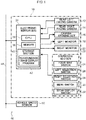
- an onboard system 46 includes a bus 48.
- Plural electronic control units which perform different control to each other, and plural sensor units are each connected to the bus 48. Note that only parts of the onboard system 46 that are relevant to the present disclosure are illustrated in Fig. 1 .
- Each of the electronic control units is a control unit including a CPU, memory, and a non-volatile storage section, and is hereafter referred to as an ECU.
- An electronic mirror ECU 34 is included among the plural ECUs connected to the bus 48.
- a vehicle speed sensor 50 is included in the plural sensor units connected to the bus 48.
- a rear-left facing camera 12, a rear-right facing camera 14, a camera stowing actuator (ACT) 16, a left monitor 18, a right monitor 20, and an operation section 22 (an operation interface) are each connected to the electronic mirror ECU 34.
- the electronic mirror ECU 34, the rear-left facing camera 12, the rear-right facing camera 14, the camera stowing ACT 16, the left monitor 18, the right monitor 20, and the operation section 22 collectively configure an electronic outer mirror device 10.
- the electronic outer mirror device 10 is an example of a vehicle surroundings display device.
- the rear-left facing camera 12 and the rear-right facing camera 14 are an example of plural imaging sections
- the left monitor 18 and the right monitor 20 are an example of a display section
- the operation section 22 is an example of an operation section
- the electronic mirror ECU 34 is an example of a display controller.
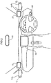
- a base portion of a substantially rectangular block shaped camera support body 54L is attached to a vehicle front side end portion of a vehicle vertical direction intermediate section of a left side door (front side door, not illustrated in the drawings) of a vehicle, such that a circular arc shaped leading end portion of the camera support body 54L projects toward the vehicle outer side.
- the rear-left facing camera 12 is attached near to the leading end portion of the camera support body 54L.
- An imaging optical axis (lens) of the rear-left facing camera 12 is directed toward the rear-left of the vehicle, and captures images at the rear-left of the vehicle.
- the camera support body 54L is capable of swinging in the vehicle front-rear direction under drive force of the camera stowing ACT 16 so as to be swung to a stowed position where the length direction of the camera support body 54L substantially follows an outer side face of the vehicle, or to a deployed position where the rear-left facing camera 12 captures images at the rear-left of the vehicle.
- a base portion of a camera support body 54R which has a profile with left-right symmetry to the camera support body 54L, is attached to a vehicle front side end portion of a vehicle vertical direction intermediate section of a right side door (front side door, not illustrated in the drawings) of the vehicle.
- the rear-right facing camera 14 is attached near to a leading end portion of the camera support body 54R.
- An imaging optical axis (lens) of the rear-right facing camera 14 is directed toward the rear-right of the vehicle, and captures images at the rear-right of the vehicle.
- the camera support body 54R is also capable of swinging in the vehicle front-rear direction under drive force of the camera stowing ACT 16 so as to be swung to a stowed position where the length direction of the camera support body 54R substantially follows an outer side face of the vehicle, or to a deployed position where the rear-right facing camera 14 captures images at the rear-right of the vehicle.
- the lenses of the rear-left facing camera 12 and the rear-right facing camera 14 each have a fixed focal point and a relatively wide view angle. Mechanisms to modify the orientations of the imaging optical axes are not provided.
- the rear-left facing camera 12 captures images of a relatively wide, fixed imaging region at the rear-left of the vehicle.
- the rear-right facing camera 14 captures images of a relatively wide, fixed imaging region at the rear-right of the vehicle.
- the left monitor 18 is provided in a vehicle cabin interior near to a lower end of a left front pillar.
- An image (video image) representing the rear-left captured by the rear-left facing camera 12 is displayed on the left monitor 18 by the electronic mirror ECU 34.
- the left monitor 18 has a function replacing that of a left outer mirror. An occupant is able to check the situation in a restricted view region at the rear-left of the vehicle by viewing the image displayed on the left monitor 18.
- the right monitor 20 is provided in the vehicle cabin interior near to a lower end of a right front pillar.
- An image (video image) representing the rear-right captured by the rear-right facing camera 14 is displayed on the right monitor 20 by the electronic mirror ECU 34.
- the right monitor 20 has a function replacing that of a right outer mirror. The occupant is able to check the situation in a restricted view region at the rear-right of the vehicle by viewing the image displayed on the right monitor 20.
- a central monitor 56 is provided at a central portion of an instrument panel of the vehicle.
- An inner rear view mirror 58 is provided at a position separate from and at the vehicle upper side of the central monitor 56.
- the inner rear view mirror 58 is an optical mirror. The orientation of the mirror surface of the inner rear view mirror 58 is adjusted so as to reflect a restricted view region behind the vehicle.
- the operation section 22 is an operation interface disposed toward the vehicle lower side of a right end of the instrument panel. As illustrated in Fig. 3 , the operation section 22 includes a four-way switch 24 that enables input of an operation to instruct a movement direction of an image display range of the left monitor 18 or the right monitor 20. The movement is split into four directions corresponding to the upper, lower, left, and right directions of the vehicle. More specifically, the four-way switch 24 includes four switches respectively corresponding to the upper, lower, left, and right directions, and the respective switches are switched ON by pressing an operation button of the four-way switch 24 at different locations (namely, on the upper side, the lower side, the left side, or the right side of the operation button). The occupant is therefore able to instruct a desired direction out of the four directions by selecting and pressing a corresponding pressing location on the operation button of the four-way switch 24.
- the operation section 22 also includes a left selection switch 26 enabling selection of a display image on the left monitor 18 as an instruction target of the four-way switch 24, and a right selection switch 28 enabling designation of a display image on the right monitor 20 as an instruction target of the four-way switch 24.
- the left selection switch 26 and the right selection switch 28 are switched between an ON state and an OFF state each time they are pressed.
- the operation section 22 also includes a menu switch 30 enabling instruction of a menu screen display, and a stow/deploy switch 32 enabling instruction of swinging of the camera support bodies 54L, 54R. Note that the operation section 22 is an example of an operation section, the four-way switch 24 is an example of a first operation section, and the left selection switch 26 and the right selection switch 28 are an example of a second operation section.
- the electronic mirror ECU 34 includes a CPU 36, memory 38, and a storage section 40, which is a non-volatile memory.
- a surroundings image display program 42 is stored in the storage section 40.
- the electronic mirror ECU 34 performs surroundings image display processing, described later, by reading the surroundings image display program 42 from the storage section 40, expanding the surroundings image display program 42 in the memory 38, and executing the surroundings image display program 42 expanded in the memory 38 using the CPU 36.
- the electronic mirror ECU 34 swings the camera support bodies 54L, 54R to either the stowed position or the deployed position using the camera stowing ACT 16.
- the menu switch 30 When the menu switch 30 is switched ON, the electronic mirror ECU 34 displays a menu screen in which plural items relating to the electronic outer mirror device 10 are displayed in a selectable list on the right monitor 20 or the central monitor 56, for example.
- the items displayed in the list on the menu screen include brightness adjustment of the images displayed on the left and right monitors 18, 20.
- the occupant operates the four-way switch 24, the left selection switch 26, or the right selection switch 28 to select particular items, instruct adjustment of the image brightness, or the like. Detailed explanation thereof is omitted herein.
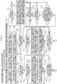
- the electronic mirror ECU 34 performs the surroundings image display processing illustrated in Fig. 4 while an ignition switch of the vehicle is switched ON, and the camera support bodies 54L, 54R are positioned in their respective deployed positions. Explanation follows regarding this surroundings image display processing.
- the image illustrated in Fig. 5 corresponds to the entire range of an example image captured by the rear-right facing camera 14 (or the rear-left facing camera 12).
- the electronic mirror ECU 34 crops an image in a display range corresponding to a standard view angle from both left and right captured images captured by the cameras 12, 14, and resizes the cropped images electronically for display over the entire screens of the left and right monitors 18, 20.
- Fig. 6 illustrates an example of a display range corresponding to a standard view angle set with respect to the captured image illustrated in Fig. 5 , as framed by white intermittent lines.
- FIG. 7 illustrates an example of an image at the standard view angle displayed on the monitor 18 or 20 in a case in which the display range corresponds to the position illustrated in Fig. 6 .
- Separate display range positions set with respect to the captured images are stored for the left and right in the storage section 40.
- the electronic mirror ECU 34 reads the respective display range positions set for a rear-left captured image captured by the rear-left facing camera 12 and for a rear-right captured image captured by the rear-right facing camera 14 from the storage section 40.
- initial display range positions may for example be positions corresponding to the respective centers of the rear-left captured image and the rear-right captured image.
- the electronic mirror ECU 34 crops the rear-left captured image to an image corresponding to the inside of the display range when the display range is disposed at the aforementioned position on the rear-left captured image.
- the electronic mirror ECU 34 then electronically resizes the image cropped from the rear-left captured image to be displayed over the entire screen of the left monitor 18 as a standard view angle image.
- the electronic mirror ECU 34 crops the rear-right captured image to an image corresponding to the inside of the display range when the display range is disposed at the aforementioned position on the rear-right captured image.
- the electronic mirror ECU 34 then electronically resizes the image cropped from the rear-right captured image to be displayed over the entire screen of the right monitor 20 as a standard view angle image.
- An example of a standard view angle image displayed on the monitor 18 or 20 at step 102 or 104 is illustrated in Fig. 7 .
- the view angle of the standard view angle image is an example of a first view angle.
- the electronic mirror ECU 34 determines whether or not the left selection switch 26 has been switched ON. In cases in which determination is negative at step 106 processing transitions to step 108. At step 108, the electronic mirror ECU 34 determines whether or not the right selection switch 28 has been switched ON. In cases in which determination is negative at step 108 processing transitions to step 110. At step 110, the electronic mirror ECU 34 determines whether or not the four-way switch 24 has been operated. In cases in which determination is also negative at step 110 processing returns to step 106. Steps 106, 108, and 110 are then repeated until determination is affirmative at one out of the steps 106, 108, or 110.
- step 112 the electronic mirror ECU 34 determines whether or not the four-way switch 24 has been operated. In cases in which determination is negative at step 112 processing transitions to step 118. At step 118, the electronic mirror ECU 34 determines whether or not the left selection switch 26 has been switched OFF, or whether or not the right selection switch 28 has been switched ON. In cases in which determination is negative at step 118 processing returns to step 112, and the processing of steps 112 and 118 is repeated until determination is affirmative at either step.
- step 112 In a state in which the left selection switch 26 is switched ON and steps 112, 118 are being repeated, in cases in which any of the switches included in the four-way switch 24 is switched ON by the occupant performing a press operation at a desired location on the four-way switch 24 of the operation section 22, determination is affirmative at step 112 and processing transitions to step 114.
- an operation condition of affirmative determination at step 112 is an example of a second operation condition.
- the electronic mirror ECU 34 moves the position of the display range set with respect to a rear-left captured image according to the operation of the four-way switch 24.
- the position of the display range on the rear-left captured image is moved in the left direction at a constant speed while the switch remains ON.
- the switch of the four-way switch 24 corresponding to the right direction has been switched ON, as illustrated by the arrow R in Fig. 6 , the position of the display range on the rear-left captured image is moved in the right direction at a constant speed while the switch remains ON.
- the electronic mirror ECU 34 crops an image corresponding to the display range after being moved from the rear-left captured image, and electronically resizes the image cropped from the rear-left captured image to be displayed over the entire screen of the left monitor 18 as a standard view angle image.
- the electronic mirror ECU 34 stores the position of the display range after being moved in the storage section 40, and processing transitions to step 118.
- the left selection switch 26 remains in an ON state, each time the four-way switch 24 is operated, the position of the display range on the rear-left captured image is moved according to operation of the four-way switch 24, the standard view angle image displayed on the left monitor 18 is switched according to the movement of the display range, and the position of the display range with respect to the rear-left captured image stored in the storage section 40 is updated to the position of the display range after being moved.
- step 112 and 118 In a state in which steps 112 and 118 are being repeated, if the left selection switch 26 is switched OFF due to the occupant repeating press operation of the left selection switch 26, or if the right selection switch 28 is switched ON by the occupant performing a press operation of the right selection switch 28, determination is affirmative at step 118, and processing returns to the loop of steps 106, 108, and 110. Note that if the right selection switch 28 is switched ON, the left selection switch 26 that was in the ON state is automatically switched OFF.
- step 120 the electronic mirror ECU 34 determines whether or not the four-way switch 24 has been operated. In cases in which determination is negative at step 120 processing transitions to step 126. At step 126, the electronic mirror ECU 34 determines whether or not the right selection switch 28 has been switched OFF, or whether or not the left selection switch 26 has been switched ON. In cases in which determination is negative at step 126 processing returns to step 120, and the processing of steps 120 and 126 is repeated until determination is affirmative at either step.
- step 120 In a state in which the right selection switch 28 is switched ON and steps 120, 126 are being repeated, in cases in which any of the switches included in the four-way switch 24 is switched ON by the occupant performing a press operation of a desired location on the four-way switch 24 of the operation section 22, determination is affirmative at step 120 and processing transitions to step 122. Note that an operation condition of affirmative determination at step 120 is an example of the second operation condition.
- the electronic mirror ECU 34 moves the position of a display range set with respect to a rear-right captured image according to operation of the four-way switch 24, crops an image corresponding to the display range after being moved from the rear-right captured image, and electronically resizes the image cropped from the rear-right captured image for display over the entire screen of the right monitor 20 as a standard view angle image.
- the electronic mirror ECU 34 stores the position of the display range after being moved in the storage section 40, and processing transitions to step 126.
- the right selection switch 28 While the right selection switch 28 remains in an ON state, each time the four-way switch 24 is operated, the position of the display range on the rear-right captured image is moved according to operation of the four-way switch 24, the standard view angle image displayed on the right monitor 20 is switched according to the movement of the display range, and the position of the display range with respect to the rear-right captured image stored in the storage section 40 is updated to the position of the display range after being moved.
- steps 120 and 126 are being repeated, if the right selection switch 28 is switched OFF, or if the left selection switch 26 is switched ON, determination is affirmative at step 126, and processing returns to the loop of steps 106, 108, and 110.
- step 110 In a state in which steps 106, 108, and 110 are being repeated, in cases in which any of the switches included in the four-way switch 24 is switched ON by the occupant performing a press operation of a desired location on the four-way switch 24 of the operation section 22, determination is affirmative at step 110 and processing transitions to step 128.
- an operation condition of affirmative determination at step 110 is an example of a first operation condition.
- the electronic mirror ECU 34 electronically resizes the entirety of the rear-left captured image captured by the rear-left facing camera 12 for display over the entire screen of the left monitor 18 as a wide angle image, and electronically resizes the entirety of the rear-right captured image captured by the rear-right facing camera 14 to be displayed over the entire screen of the right monitor 20 as a wide angle image.
- An example of a wide angle image displayed on the monitor 18, 20 at step 128 is illustrated in Fig. 5 .
- the view angle of a wide angle image is an example of a second view angle.
- the electronic mirror ECU 34 determines whether or not the left selection switch 26 or the right selection switch 28 has been switched ON. In cases in which determination is negative at step 130 processing transitions to step 132. At step 132, the electronic mirror ECU 34 determines whether or not the four-way switch 24 has been operated. In cases in which determination is negative at step 132 processing transitions to step 134. At step 134, the electronic mirror ECU 34 determines whether or not a state in which the vehicle speed detected by the vehicle speed sensor 50 is a predetermined value or greater has continued for a specific duration or longer. Note that an example of the predetermined value is 30 km/h, and an example of the specific duration is 15 seconds.
- step 132 processing returns to step 130.
- the processing of steps 130, 132, and 134 is then repeated until determination is affirmative at any of steps 130, 132, or 134.
- the wide angle images continue to be displayed on the left monitor 18 and the right monitor 20 while this is occurring.
- step 130 In a state in which steps 130, 132, and 134 are being repeated, in cases in which the left selection switch 26 or the right selection switch 28 is switched ON, determination is affirmative at step 130 and processing returns to step 100. In the state in which steps 130, 132, and 134 are being repeated, in cases in which the four-way switch 24 is operated, determination is affirmative at step 132 and processing returns to step 100. In the state in which steps 130, 132, and 134 are being repeated, in cases in which the state in which the vehicle speed is the predetermined value or greater has continued for the specific duration or longer, determination is affirmative at step 134 and processing returns to step 100.
- the images displayed on the monitors 18, 20 are switched from wide angle images to standard view angle images after performing steps 100 to 104.
- the ranges displayed as the standard view angle images when this is performed are the same as the display ranges stored in the storage section 40, namely, the display ranges when the standard view angle images were displayed directly prior to displaying the wide angle images.
- the operation section 22 includes the four-way switch 24 enabling input of operations to instruct the movement direction of the range of an image to be displayed on the monitor 18 or 20, and the selection switches 26, 28 enabling input of an operation to designate a target image from out of the plural images.
- the electronic mirror ECU 34 switches between a mode in which the images displayed on the monitors 18, 20 are modified under the first operation condition in which the four-way switch 24 has been operated in a state in which a target image has not been designated using the selection switches 26, 28, and a mode in which an image displayed on the monitor 18 or 20 is modified under a second operation condition in which the four-way switch 24 is operated in a state in which a target image has been designated using the selection switch 26 or 28.
- the configuration of the operation section 22 is accordingly essentially no different to that of an existing electric optical mirror device, and differences from existing electric optical mirror devices in terms of the operation interface are suppressed. This suppresses any uncertainty felt by an occupant accustomed to the operation of an existing electric optical mirror device.
- the present exemplary embodiment enables a difference in configuration of the operation section and a difference in the operation interface in comparison to that of an existing electric optical mirror device to be suppressed.
- there is essentially no difference between the configuration of the operation section 22 and that of an existing electric optical mirror device in cases in which either the electronic outer mirror device 10 or an electric optical mirror device is selectively installed to the same model of vehicle, an increase in costs arising from differences in the configuration of the operation section 22 can be suppressed.
- the electronic mirror ECU 34 modifies the respective view angles of the plural images displayed on the monitors 18, 20, thereby enabling the difference between the operation interface and that of an existing electric optical mirror device to be further reduced, and enabling any uncertainty felt by an occupant accustomed to the operation of the existing electric optical mirror device to be further suppressed.
- the electronic mirror ECU 34 moves the display range of the target image on the monitor 18 or 20, as designated using the selection switch 26 or 28, in a direction corresponding to operation of the four-way switch 24. This enables the difference between the operation interface and that of an existing electric optical mirror device to be further reduced, thus enabling any uncertainty felt by an occupant accustomed to the operation of the existing electric optical mirror device to be further suppressed.
- the electronic mirror ECU 34 switches the displays to the standard view angle images. This increases the size of image regions corresponding to objects present in the environs of the vehicle in the images displayed on the monitors 18, 20. This makes it easier for an occupant to recognize the presence of these objects, enabling safety during vehicle travel to be improved.
- the electronic mirror ECU 34 stores in the storage section 40 the display ranges of images on the monitors 18, 20 for the state in which standard view angle images are displayed on the monitors 18, 20.
- the electronic mirror ECU 34 displays images on the monitors 18, 20 according to the display ranges stored in the storage section 40. This reduces the likelihood of needing to adjust the display ranges of the standard view angle images displayed on the monitors 18, 20 when the displays are switched from the wide angle images to the standard view angle images, thereby enabling ease of operation to be improved.
- a function to modify the orientations of the imaging optical axes of the rear-left facing camera 12 and the rear-right facing camera 14 is not provided.
- this function may be provided to the left and right cameras 12, 14, and the ranges displayed as images on the monitors 18, 20 may be moved by modifying the orientations of the imaging optical axes of the cameras 12, 14.
- the lenses of the rear-left facing camera 12 and the rear-right facing camera 14 each have a fixed focal point and a comparatively wide view angle.
- the lenses of the left and right cameras 12, 14 may be zoom lenses, and the view angles of the images displayed on the monitors 18, 20 may be modified by modifying the magnification of the zoom lenses.
- the image displayed on the left monitor 18 is captured by the rear-left facing camera 12, and the image displayed on the right monitor 20 is captured by the rear-right facing camera 14.
- plural cameras may be provided as cameras imaging at the left side of the vehicle, and a composite image of the images captured by these cameras may be displayed on the left monitor 18.
- plural cameras may be provided as cameras imaging at the right side of the vehicle, and a composite image of the images captured by these cameras may be displayed on the right monitor 20.
- the images captured by the left and right cameras 12, 14 are displayed on the left and right monitors 18, 20.
- left and right images captured by the left and right cameras 12, 14 may be displayed on the central monitor 56.
- the inner rear view mirror 58 may be configured so as to be capable of displaying images, and the left and right images may be displayed thereon.
- the display range of the standard view angle images displayed on the left monitor 18 or the right monitor 20 is only moved in cases in which either the left selection switch 26 or the right selection switch 28 has been switched ON and the four-way switch 24 has been operated.
- reverse-coordinated control in which the display ranges of the standard view angle images are moved toward the vehicle lower side to facilitate viewing of obstacles at the lower side at the side of the vehicle while the vehicle is reversing
- turning-coordinated control in which the display ranges of the standard view angle images are moved in coordination with operation of a direction indicator to facilitate viewing behind the vehicle, or the like may be performed.
- the view angles of the images displayed on the monitors 18, 20 are modified between two levels, these being the standard view angle images and the wide angle images.
- the view angles may be modified in three or more plural increments, whereby in a state in which the left selection switch 26 and the right selection switch 28 are not switched ON, the view angles of the images are switched to a wider angle each time the switch of the four-way switch 24 corresponding to the upward direction is switched ON, and the view angles of the images are switched to a narrower angle each time the switch of the four-way switch 24 corresponding to the downward direction is switched ON.
- the single electronic mirror ECU 34 is provided as the display controller of the left and right cameras 12, 14 and the left and right monitors 18, 20.
- a first display controller controlling the rear-left facing camera 12 and the left monitor 18, and a second display controller controlling the rear-right facing camera 14 and the right monitor 20 may be respectively provided, with the first display controller and the second display controller being configured so as to communicate as required.
Landscapes
- Engineering & Computer Science (AREA)
- Multimedia (AREA)
- Mechanical Engineering (AREA)
- Closed-Circuit Television Systems (AREA)
Applications Claiming Priority (1)
| Application Number | Priority Date | Filing Date | Title |
|---|---|---|---|
| JP2018099400A JP7102938B2 (ja) | 2018-05-24 | 2018-05-24 | 車両用周辺表示装置 |
Publications (2)
| Publication Number | Publication Date |
|---|---|
| EP3572284A1 true EP3572284A1 (de) | 2019-11-27 |
| EP3572284B1 EP3572284B1 (de) | 2020-07-29 |
Family
ID=66589224
Family Applications (1)
| Application Number | Title | Priority Date | Filing Date |
|---|---|---|---|
| EP19174722.9A Active EP3572284B1 (de) | 2018-05-24 | 2019-05-15 | Fahrzeugumgebungsanzeigevorrichtung |
Country Status (4)
| Country | Link |
|---|---|
| US (1) | US10647260B2 (de) |
| EP (1) | EP3572284B1 (de) |
| JP (1) | JP7102938B2 (de) |
| CN (1) | CN110525341B (de) |
Families Citing this family (4)
| Publication number | Priority date | Publication date | Assignee | Title |
|---|---|---|---|---|
| JP7147255B2 (ja) * | 2018-05-11 | 2022-10-05 | トヨタ自動車株式会社 | 画像表示装置 |
| JP7073991B2 (ja) | 2018-09-05 | 2022-05-24 | トヨタ自動車株式会社 | 車両用周辺表示装置 |
| JP7038643B2 (ja) * | 2018-11-26 | 2022-03-18 | 本田技研工業株式会社 | 映像表示装置 |
| DE102023109241B3 (de) * | 2023-04-12 | 2024-02-01 | Audi Aktiengesellschaft | Verfahren und System zum Darstellen einer Umgebung eines Fahrzeugs |
Citations (5)
| Publication number | Priority date | Publication date | Assignee | Title |
|---|---|---|---|---|
| JP2003095028A (ja) * | 2001-09-20 | 2003-04-03 | Nippon Seiki Co Ltd | 車両用監視装置 |
| JP2008148059A (ja) | 2006-12-11 | 2008-06-26 | Denso Corp | 車両周辺監視装置 |
| US20160227123A1 (en) * | 2015-02-02 | 2016-08-04 | Kabushiki Kaisha Tokai Rika Denki Seisakusho | Mirror control device and mirror control system |
| DE102016112817A1 (de) * | 2015-07-16 | 2017-01-19 | Kabushiki Kaisha Tokai-Rika-Denki-Seisakusho | Elektronisches Fahrzeugspiegelsystem |
| WO2017199888A1 (ja) * | 2016-05-19 | 2017-11-23 | 株式会社東海理化電機製作所 | 車両用視認装置 |
Family Cites Families (10)
| Publication number | Priority date | Publication date | Assignee | Title |
|---|---|---|---|---|
| US20070035625A9 (en) * | 2002-12-20 | 2007-02-15 | Hamdan Majed M | Vehicle video processing system |
| US20130293683A1 (en) * | 2012-05-03 | 2013-11-07 | Harman International (Shanghai) Management Co., Ltd. | System and method of interactively controlling a virtual camera |
| TWI535587B (zh) * | 2012-11-14 | 2016-06-01 | 義晶科技股份有限公司 | 利用觸控面板來控制車用影像之顯示的方法及其車用影像系統 |
| KR102263723B1 (ko) * | 2014-11-12 | 2021-06-11 | 현대모비스 주식회사 | 어라운드 뷰 모니터 시스템 및 그 제어방법 |
| US9654687B2 (en) * | 2014-12-24 | 2017-05-16 | Agamemnon Varonos | Panoramic windshield viewer system |
| JP6206395B2 (ja) | 2014-12-26 | 2017-10-04 | トヨタ自動車株式会社 | 電子ミラー装置 |
| JP6602721B2 (ja) * | 2016-04-15 | 2019-11-06 | 株式会社東海理化電機製作所 | 車両用視認装置 |
| JP2017202741A (ja) * | 2016-05-11 | 2017-11-16 | 株式会社東海理化電機製作所 | 車両用視認装置 |
| JP6390035B2 (ja) * | 2016-05-23 | 2018-09-19 | 本田技研工業株式会社 | 車両制御システム、車両制御方法、および車両制御プログラム |
| JP2018043643A (ja) * | 2016-09-14 | 2018-03-22 | 株式会社東海理化電機製作所 | 車両用視認装置 |
-
2018
- 2018-05-24 JP JP2018099400A patent/JP7102938B2/ja active Active
-
2019
- 2019-05-10 CN CN201910387997.3A patent/CN110525341B/zh active Active
- 2019-05-14 US US16/411,564 patent/US10647260B2/en active Active
- 2019-05-15 EP EP19174722.9A patent/EP3572284B1/de active Active
Patent Citations (5)
| Publication number | Priority date | Publication date | Assignee | Title |
|---|---|---|---|---|
| JP2003095028A (ja) * | 2001-09-20 | 2003-04-03 | Nippon Seiki Co Ltd | 車両用監視装置 |
| JP2008148059A (ja) | 2006-12-11 | 2008-06-26 | Denso Corp | 車両周辺監視装置 |
| US20160227123A1 (en) * | 2015-02-02 | 2016-08-04 | Kabushiki Kaisha Tokai Rika Denki Seisakusho | Mirror control device and mirror control system |
| DE102016112817A1 (de) * | 2015-07-16 | 2017-01-19 | Kabushiki Kaisha Tokai-Rika-Denki-Seisakusho | Elektronisches Fahrzeugspiegelsystem |
| WO2017199888A1 (ja) * | 2016-05-19 | 2017-11-23 | 株式会社東海理化電機製作所 | 車両用視認装置 |
Also Published As
| Publication number | Publication date |
|---|---|
| JP7102938B2 (ja) | 2022-07-20 |
| US20190359141A1 (en) | 2019-11-28 |
| US10647260B2 (en) | 2020-05-12 |
| CN110525341B (zh) | 2022-12-27 |
| JP2019205075A (ja) | 2019-11-28 |
| EP3572284B1 (de) | 2020-07-29 |
| CN110525341A (zh) | 2019-12-03 |
Similar Documents
| Publication | Publication Date | Title |
|---|---|---|
| EP3572284B1 (de) | Fahrzeugumgebungsanzeigevorrichtung | |
| JP7128096B2 (ja) | 映像表示装置 | |
| CN107298050B (zh) | 图像显示装置 | |
| JP5064601B2 (ja) | 車載用映像表示装置 | |
| JP2003081014A (ja) | 車両周辺監視装置 | |
| JP2008301091A (ja) | 車両用周辺監視装置 | |
| JP2013054720A (ja) | 運転支援装置 | |
| US11024011B2 (en) | Image display apparatus and image display method | |
| JP3832455B2 (ja) | 車輌周囲表示装置 | |
| JP2006311272A (ja) | 車両用映像表示装置 | |
| JP2018088642A (ja) | 車両用ミラーシステム | |
| US20190087665A1 (en) | Information processing apparatus and program | |
| JP2018144554A (ja) | 車両用ヘッドアップディスプレイ装置 | |
| JP2019116220A (ja) | 車両用視認装置 | |
| JP2005236493A (ja) | 運転支援装置 | |
| KR101941607B1 (ko) | 차량용 촬영 표시 장치 및 기록 매체 | |
| JP4849333B2 (ja) | 車両用視覚補助装置 | |
| US11372110B2 (en) | Image display apparatus | |
| US11214195B2 (en) | Electronic mirror system | |
| JP7166725B2 (ja) | 表示装置、表示方法および表示プログラム | |
| JP6848779B2 (ja) | 電子ミラーシステム | |
| US20200166641A1 (en) | Image display apparatus | |
| JP2006137282A (ja) | リモコン装置および車両用表示装置 | |
| JP2016141303A (ja) | 視界支援装置 | |
| JP4285229B2 (ja) | 車両用表示装置 |
Legal Events
| Date | Code | Title | Description |
|---|---|---|---|
| PUAI | Public reference made under article 153(3) epc to a published international application that has entered the european phase |
Free format text: ORIGINAL CODE: 0009012 |
|
| STAA | Information on the status of an ep patent application or granted ep patent |
Free format text: STATUS: REQUEST FOR EXAMINATION WAS MADE |
|
| 17P | Request for examination filed |
Effective date: 20190515 |
|
| AK | Designated contracting states |
Kind code of ref document: A1 Designated state(s): AL AT BE BG CH CY CZ DE DK EE ES FI FR GB GR HR HU IE IS IT LI LT LU LV MC MK MT NL NO PL PT RO RS SE SI SK SM TR |
|
| AX | Request for extension of the european patent |
Extension state: BA ME |
|
| GRAP | Despatch of communication of intention to grant a patent |
Free format text: ORIGINAL CODE: EPIDOSNIGR1 |
|
| STAA | Information on the status of an ep patent application or granted ep patent |
Free format text: STATUS: GRANT OF PATENT IS INTENDED |
|
| INTG | Intention to grant announced |
Effective date: 20200518 |
|
| GRAS | Grant fee paid |
Free format text: ORIGINAL CODE: EPIDOSNIGR3 |
|
| GRAA | (expected) grant |
Free format text: ORIGINAL CODE: 0009210 |
|
| STAA | Information on the status of an ep patent application or granted ep patent |
Free format text: STATUS: THE PATENT HAS BEEN GRANTED |
|
| AK | Designated contracting states |
Kind code of ref document: B1 Designated state(s): AL AT BE BG CH CY CZ DE DK EE ES FI FR GB GR HR HU IE IS IT LI LT LU LV MC MK MT NL NO PL PT RO RS SE SI SK SM TR |
|
| REG | Reference to a national code |
Ref country code: CH Ref legal event code: EP |
|
| REG | Reference to a national code |
Ref country code: DE Ref legal event code: R096 Ref document number: 602019000346 Country of ref document: DE |
|
| REG | Reference to a national code |
Ref country code: AT Ref legal event code: REF Ref document number: 1295414 Country of ref document: AT Kind code of ref document: T Effective date: 20200815 |
|
| REG | Reference to a national code |
Ref country code: IE Ref legal event code: FG4D |
|
| REG | Reference to a national code |
Ref country code: LT Ref legal event code: MG4D |
|
| REG | Reference to a national code |
Ref country code: NL Ref legal event code: MP Effective date: 20200729 |
|
| REG | Reference to a national code |
Ref country code: AT Ref legal event code: MK05 Ref document number: 1295414 Country of ref document: AT Kind code of ref document: T Effective date: 20200729 |
|
| PG25 | Lapsed in a contracting state [announced via postgrant information from national office to epo] |
Ref country code: BG Free format text: LAPSE BECAUSE OF FAILURE TO SUBMIT A TRANSLATION OF THE DESCRIPTION OR TO PAY THE FEE WITHIN THE PRESCRIBED TIME-LIMIT Effective date: 20201029 Ref country code: SE Free format text: LAPSE BECAUSE OF FAILURE TO SUBMIT A TRANSLATION OF THE DESCRIPTION OR TO PAY THE FEE WITHIN THE PRESCRIBED TIME-LIMIT Effective date: 20200729 Ref country code: AT Free format text: LAPSE BECAUSE OF FAILURE TO SUBMIT A TRANSLATION OF THE DESCRIPTION OR TO PAY THE FEE WITHIN THE PRESCRIBED TIME-LIMIT Effective date: 20200729 Ref country code: HR Free format text: LAPSE BECAUSE OF FAILURE TO SUBMIT A TRANSLATION OF THE DESCRIPTION OR TO PAY THE FEE WITHIN THE PRESCRIBED TIME-LIMIT Effective date: 20200729 Ref country code: NO Free format text: LAPSE BECAUSE OF FAILURE TO SUBMIT A TRANSLATION OF THE DESCRIPTION OR TO PAY THE FEE WITHIN THE PRESCRIBED TIME-LIMIT Effective date: 20201029 Ref country code: FI Free format text: LAPSE BECAUSE OF FAILURE TO SUBMIT A TRANSLATION OF THE DESCRIPTION OR TO PAY THE FEE WITHIN THE PRESCRIBED TIME-LIMIT Effective date: 20200729 Ref country code: PT Free format text: LAPSE BECAUSE OF FAILURE TO SUBMIT A TRANSLATION OF THE DESCRIPTION OR TO PAY THE FEE WITHIN THE PRESCRIBED TIME-LIMIT Effective date: 20201130 Ref country code: GR Free format text: LAPSE BECAUSE OF FAILURE TO SUBMIT A TRANSLATION OF THE DESCRIPTION OR TO PAY THE FEE WITHIN THE PRESCRIBED TIME-LIMIT Effective date: 20201030 Ref country code: ES Free format text: LAPSE BECAUSE OF FAILURE TO SUBMIT A TRANSLATION OF THE DESCRIPTION OR TO PAY THE FEE WITHIN THE PRESCRIBED TIME-LIMIT Effective date: 20200729 Ref country code: LT Free format text: LAPSE BECAUSE OF FAILURE TO SUBMIT A TRANSLATION OF THE DESCRIPTION OR TO PAY THE FEE WITHIN THE PRESCRIBED TIME-LIMIT Effective date: 20200729 |
|
| PG25 | Lapsed in a contracting state [announced via postgrant information from national office to epo] |
Ref country code: LV Free format text: LAPSE BECAUSE OF FAILURE TO SUBMIT A TRANSLATION OF THE DESCRIPTION OR TO PAY THE FEE WITHIN THE PRESCRIBED TIME-LIMIT Effective date: 20200729 Ref country code: PL Free format text: LAPSE BECAUSE OF FAILURE TO SUBMIT A TRANSLATION OF THE DESCRIPTION OR TO PAY THE FEE WITHIN THE PRESCRIBED TIME-LIMIT Effective date: 20200729 Ref country code: RS Free format text: LAPSE BECAUSE OF FAILURE TO SUBMIT A TRANSLATION OF THE DESCRIPTION OR TO PAY THE FEE WITHIN THE PRESCRIBED TIME-LIMIT Effective date: 20200729 Ref country code: IS Free format text: LAPSE BECAUSE OF FAILURE TO SUBMIT A TRANSLATION OF THE DESCRIPTION OR TO PAY THE FEE WITHIN THE PRESCRIBED TIME-LIMIT Effective date: 20201129 |
|
| PG25 | Lapsed in a contracting state [announced via postgrant information from national office to epo] |
Ref country code: NL Free format text: LAPSE BECAUSE OF FAILURE TO SUBMIT A TRANSLATION OF THE DESCRIPTION OR TO PAY THE FEE WITHIN THE PRESCRIBED TIME-LIMIT Effective date: 20200729 |
|
| PG25 | Lapsed in a contracting state [announced via postgrant information from national office to epo] |
Ref country code: RO Free format text: LAPSE BECAUSE OF FAILURE TO SUBMIT A TRANSLATION OF THE DESCRIPTION OR TO PAY THE FEE WITHIN THE PRESCRIBED TIME-LIMIT Effective date: 20200729 Ref country code: CZ Free format text: LAPSE BECAUSE OF FAILURE TO SUBMIT A TRANSLATION OF THE DESCRIPTION OR TO PAY THE FEE WITHIN THE PRESCRIBED TIME-LIMIT Effective date: 20200729 Ref country code: DK Free format text: LAPSE BECAUSE OF FAILURE TO SUBMIT A TRANSLATION OF THE DESCRIPTION OR TO PAY THE FEE WITHIN THE PRESCRIBED TIME-LIMIT Effective date: 20200729 Ref country code: EE Free format text: LAPSE BECAUSE OF FAILURE TO SUBMIT A TRANSLATION OF THE DESCRIPTION OR TO PAY THE FEE WITHIN THE PRESCRIBED TIME-LIMIT Effective date: 20200729 Ref country code: IT Free format text: LAPSE BECAUSE OF FAILURE TO SUBMIT A TRANSLATION OF THE DESCRIPTION OR TO PAY THE FEE WITHIN THE PRESCRIBED TIME-LIMIT Effective date: 20200729 Ref country code: SM Free format text: LAPSE BECAUSE OF FAILURE TO SUBMIT A TRANSLATION OF THE DESCRIPTION OR TO PAY THE FEE WITHIN THE PRESCRIBED TIME-LIMIT Effective date: 20200729 |
|
| REG | Reference to a national code |
Ref country code: DE Ref legal event code: R097 Ref document number: 602019000346 Country of ref document: DE |
|
| PG25 | Lapsed in a contracting state [announced via postgrant information from national office to epo] |
Ref country code: AL Free format text: LAPSE BECAUSE OF FAILURE TO SUBMIT A TRANSLATION OF THE DESCRIPTION OR TO PAY THE FEE WITHIN THE PRESCRIBED TIME-LIMIT Effective date: 20200729 |
|
| PLBE | No opposition filed within time limit |
Free format text: ORIGINAL CODE: 0009261 |
|
| STAA | Information on the status of an ep patent application or granted ep patent |
Free format text: STATUS: NO OPPOSITION FILED WITHIN TIME LIMIT |
|
| PG25 | Lapsed in a contracting state [announced via postgrant information from national office to epo] |
Ref country code: SK Free format text: LAPSE BECAUSE OF FAILURE TO SUBMIT A TRANSLATION OF THE DESCRIPTION OR TO PAY THE FEE WITHIN THE PRESCRIBED TIME-LIMIT Effective date: 20200729 |
|
| 26N | No opposition filed |
Effective date: 20210430 |
|
| PG25 | Lapsed in a contracting state [announced via postgrant information from national office to epo] |
Ref country code: LU Free format text: LAPSE BECAUSE OF NON-PAYMENT OF DUE FEES Effective date: 20210515 Ref country code: MC Free format text: LAPSE BECAUSE OF FAILURE TO SUBMIT A TRANSLATION OF THE DESCRIPTION OR TO PAY THE FEE WITHIN THE PRESCRIBED TIME-LIMIT Effective date: 20200729 |
|
| REG | Reference to a national code |
Ref country code: BE Ref legal event code: MM Effective date: 20210531 |
|
| PG25 | Lapsed in a contracting state [announced via postgrant information from national office to epo] |
Ref country code: IE Free format text: LAPSE BECAUSE OF NON-PAYMENT OF DUE FEES Effective date: 20210515 |
|
| PG25 | Lapsed in a contracting state [announced via postgrant information from national office to epo] |
Ref country code: BE Free format text: LAPSE BECAUSE OF NON-PAYMENT OF DUE FEES Effective date: 20210531 |
|
| REG | Reference to a national code |
Ref country code: CH Ref legal event code: PL |
|
| PG25 | Lapsed in a contracting state [announced via postgrant information from national office to epo] |
Ref country code: LI Free format text: LAPSE BECAUSE OF NON-PAYMENT OF DUE FEES Effective date: 20220531 Ref country code: CH Free format text: LAPSE BECAUSE OF NON-PAYMENT OF DUE FEES Effective date: 20220531 |
|
| P01 | Opt-out of the competence of the unified patent court (upc) registered |
Effective date: 20230427 |
|
| REG | Reference to a national code |
Ref country code: DE Ref legal event code: R084 Ref document number: 602019000346 Country of ref document: DE |
|
| PG25 | Lapsed in a contracting state [announced via postgrant information from national office to epo] |
Ref country code: CY Free format text: LAPSE BECAUSE OF FAILURE TO SUBMIT A TRANSLATION OF THE DESCRIPTION OR TO PAY THE FEE WITHIN THE PRESCRIBED TIME-LIMIT Effective date: 20200729 |
|
| PG25 | Lapsed in a contracting state [announced via postgrant information from national office to epo] |
Ref country code: HU Free format text: LAPSE BECAUSE OF FAILURE TO SUBMIT A TRANSLATION OF THE DESCRIPTION OR TO PAY THE FEE WITHIN THE PRESCRIBED TIME-LIMIT; INVALID AB INITIO Effective date: 20190515 |
|
| REG | Reference to a national code |
Ref country code: GB Ref legal event code: 746 Effective date: 20230815 |
|
| PG25 | Lapsed in a contracting state [announced via postgrant information from national office to epo] |
Ref country code: SI Free format text: LAPSE BECAUSE OF FAILURE TO SUBMIT A TRANSLATION OF THE DESCRIPTION OR TO PAY THE FEE WITHIN THE PRESCRIBED TIME-LIMIT Effective date: 20200729 |
|
| PG25 | Lapsed in a contracting state [announced via postgrant information from national office to epo] |
Ref country code: MK Free format text: LAPSE BECAUSE OF FAILURE TO SUBMIT A TRANSLATION OF THE DESCRIPTION OR TO PAY THE FEE WITHIN THE PRESCRIBED TIME-LIMIT Effective date: 20200729 |
|
| PG25 | Lapsed in a contracting state [announced via postgrant information from national office to epo] |
Ref country code: MT Free format text: LAPSE BECAUSE OF FAILURE TO SUBMIT A TRANSLATION OF THE DESCRIPTION OR TO PAY THE FEE WITHIN THE PRESCRIBED TIME-LIMIT Effective date: 20200729 |
|
| PGFP | Annual fee paid to national office [announced via postgrant information from national office to epo] |
Ref country code: FR Payment date: 20250310 Year of fee payment: 7 |
|
| PGFP | Annual fee paid to national office [announced via postgrant information from national office to epo] |
Ref country code: GB Payment date: 20250327 Year of fee payment: 7 |
|
| PGFP | Annual fee paid to national office [announced via postgrant information from national office to epo] |
Ref country code: DE Payment date: 20250319 Year of fee payment: 7 |
|
| PG25 | Lapsed in a contracting state [announced via postgrant information from national office to epo] |
Ref country code: TR Free format text: LAPSE BECAUSE OF FAILURE TO SUBMIT A TRANSLATION OF THE DESCRIPTION OR TO PAY THE FEE WITHIN THE PRESCRIBED TIME-LIMIT Effective date: 20200729 |