EP3571106B1 - Anordnung zur beleuchtung eines schienenfahrzeuges und schienenfahrzeug - Google Patents
Anordnung zur beleuchtung eines schienenfahrzeuges und schienenfahrzeug Download PDFInfo
- Publication number
- EP3571106B1 EP3571106B1 EP17829991.3A EP17829991A EP3571106B1 EP 3571106 B1 EP3571106 B1 EP 3571106B1 EP 17829991 A EP17829991 A EP 17829991A EP 3571106 B1 EP3571106 B1 EP 3571106B1
- Authority
- EP
- European Patent Office
- Prior art keywords
- lighting means
- lighting
- rail vehicle
- arrangement according
- control device
- Prior art date
- Legal status (The legal status is an assumption and is not a legal conclusion. Google has not performed a legal analysis and makes no representation as to the accuracy of the status listed.)
- Active
Links
Images

Classifications
-
- B—PERFORMING OPERATIONS; TRANSPORTING
- B61—RAILWAYS
- B61D—BODY DETAILS OR KINDS OF RAILWAY VEHICLES
- B61D29/00—Lighting
-
- B—PERFORMING OPERATIONS; TRANSPORTING
- B61—RAILWAYS
- B61L—GUIDING RAILWAY TRAFFIC; ENSURING THE SAFETY OF RAILWAY TRAFFIC
- B61L15/00—Indicators provided on the vehicle or train for signalling purposes
- B61L15/02—Head or tail indicators, e.g. light
-
- B—PERFORMING OPERATIONS; TRANSPORTING
- B60—VEHICLES IN GENERAL
- B60Y—INDEXING SCHEME RELATING TO ASPECTS CROSS-CUTTING VEHICLE TECHNOLOGY
- B60Y2200/00—Type of vehicle
- B60Y2200/30—Railway vehicles
Definitions
- the invention relates to an arrangement for lighting a rail vehicle, as well as a rail vehicle with such an arrangement.
- Rail vehicles have a control device for controlling and monitoring the lighting, in particular the exterior lighting. Each lamp is individually connected to the control unit. This requires a lot of installation space for the components required here and extensive wiring over the entire length of the rail vehicle, which is subject to increased susceptibility to errors. Furthermore, such a wiring to be laid over long distances has a high installation effort and a not inconsiderable mass of cables.
- One of the control units is responsible for controlling and monitoring all of the lighting. If the control unit fails, this means a complete failure of the lighting, so that emergency lighting can only be activated by means of an emergency switch. Since the control unit usually also functions as an interface to the control system, many digital inputs and outputs are required.
- the installation space in a driver's desk of a rail vehicle is, however, very limited. In addition, a possible installation space for laying cables in the area of walls and ceilings is also limited in other areas of the rail vehicle.
- the document KR 2016 0085655 A describes an apparatus for controlling an LED light output of a diesel locomotive.
- this document describes an arrangement for lighting a rail vehicle, having an energy source, a control device, a lighting means, at least one electrical line for connecting the energy source to the control device and an electrical line for connecting the control device to the lighting means, the lighting means being an adjacent control device having.
- the object of the invention is to propose an arrangement for lighting a rail vehicle which eliminates the aforementioned disadvantages and ensures lighting of a rail vehicle that requires little installation space and is less prone to errors.
- Another object of the invention is to have a rail vehicle to propose such an arrangement.
- an arrangement for illuminating a rail vehicle which has at least one energy source, at least one control device and at least one lighting means.
- the energy source is connected to the at least one control device via at least one electrical line.
- the control device in turn is connected to the at least one light source via an electrical line, each light source having at least one adjacent control device, and the control device and the light source being designed integrally.
- cabling includes not only electrical lines, but also the numerous terminals and plugs that are necessary for connecting each light source to a central control device.
- the proposed arrangement is preferably used to illuminate a locomotive, in particular its exterior lighting, with use for interior lighting or other consumers such as doors or the like also being conceivable.
- control device and the lighting means are designed integrally.
- the control unit and the lighting means can be encapsulated, welded, screwed or potted in one another or with one another.
- the module formed in this way enables simple assembly and the elimination of separate and complex cabling of the control device with the illuminant. In the event of a defect, the entire module can be replaced quickly and easily. Due to the reduced number of components, maintenance and repair costs can be reduced, whereby the downtimes of rail vehicles can be greatly reduced overall.
- the at least one lighting means can also be connected to the control device in an exchangeable manner.
- the at least one control device has an interface to a control system of the rail vehicle.
- This allows the control unit to be connected directly or indirectly to the control of the rail vehicle.
- This enables information to be transmitted so that, for example, a failure of a lamp can be recognized from the driver's cab.
- the operating mode for example ON or OFF, as well as a possible dimming function
- the information can be transmitted to the vehicle driver, for example in the form of analog or digital displays or light signals.
- the control system can have an additional monitoring device that can list and analyze the states of all control devices and thus also all lamps for the purpose of maintenance or repair.
- the control system can advantageously have an additional interface for connecting analysis tools, such as notebooks, computers or test benches equipped with appropriate software.
- the control system has at least one central control device.
- Each lighting means can thus be connected to a central control device via the respective, integrally or adjacently arranged control device and coordinated by the central control device.
- the central control device can communicate with the control center and can be arranged, for example, in the vicinity or in a driver's cab.
- Such an arrangement and the use of a control device integrally connected to a lamp can greatly reduce the required amounts of cabling, including terminals, lines and plugs, since complex cabling for each individual lamp with a central control device, which is also an interface for the Represents control technology is not applicable.
- the decentralized arrangement of the adjacent control devices or those integrated in the lighting means allows the dimensioning of the central control device, which is usually arranged in the driver's cab or driver's cab, to be significantly reduced.
- the at least one control device of the at least one lighting means and the at least one control device of the control technology have wireless or wired communication links.
- Each control device can have a wireless communication interface or communication unit.
- Information and commands can be transmitted with the aid of the communication unit.
- radio, Bluetooth, WLAN, infrared connection and such transmission technology could be used. This means that cabling for the purpose of transmitting information and controlling or regulating the lighting means can be completely eliminated.
- the respective control devices can communicate wirelessly directly with a central control device or with the central control device via other control devices, which alternatively or additionally serve as repeaters Communicate with the control unit or control center.
- the existing decentralized control devices with a wireless communication interface as a repeater can also forward the information or commands from other control devices.
- the decentralized control devices and the at least one central control device can advantageously communicate jointly and separately with one another. Cabling is therefore only required for the direct power connection and can be designed in a significantly reduced form compared to the effort required to connect a wired or wired information transmission system.
- a wired communication link or communication transmission can be implemented, for example, in the form of a BUS system, such as a CAN (Controller Area Network) -BUS system.
- communication can be transmitted via optical fibers in the form of digital light signals.
- the wired or wireless communication connection has a coding.
- Clear commands are transmitted by means of a defined coding of the data. This can increase the security of the transmitted data so that the information can be protected from manipulation by third parties.
- the commands and information to be transmitted can be converted digitally or analogously in such a way that, in the case of a wired communication connection, the number of electrical lines is minimized.
- the electrical lines are designed as a bus system.
- the respective control devices can also be connected to existing BUS systems and communicate with the control system by wire.
- each control device monitors at least one light source.
- a control unit is assigned to each light source, exclusively is responsible for monitoring and controlling the assigned light source.
- the control devices that are respectively arranged on the lighting means can be designed to be smaller or less powerful than, for example, a central control device. This enables the control devices to be arranged directly next to, in or near the lighting means, which means that less cable length and components such as terminals and plugs are required compared to an arrangement with a central control device.
- the lighting means can consist of several light sources.
- the availability of redundancy through several light sources can increase operational reliability. If a light source of a lamp fails, the rail vehicle can continue to be illuminated by the remaining light sources in the lamp, possibly with slight losses in brightness, without having to switch directly to emergency lighting.
- the lighting means is designed using LED technology, xenon, halogen HDI technology.
- LED light sources for example, are very economical and have a long service life.
- Xenon lamps can be very powerful, for example, to illuminate far-reaching distances and are well suited as directional lighting.
- combinations of several different types of lamps in one or more lamps are possible, depending on the area of application.
- LEDs can be connected to a decentralized control device in such a way that they cannot be replaced.
- both components can be cast or glued together.
- lighting means or individual light sources can be integrated into a decentralized control device. This enables improved protection against environmental influences and simpler manufacture.
- each illuminant has its own fuse. If the lighting fails, the search for the source of the error can be significantly narrowed down and thus shortened, since the fuses can be assigned to the respective lamps. This also increases the operational reliability of the lighting of the rail vehicle.
- the safety device for the lighting means can be actuated manually or automatically.
- the fuse can be designed, for example, as a circuit breaker that can be activated automatically when the load is too high.
- Such a circuit breaker can be deactivated again, for example, directly or indirectly via a switch or via remote control.
- the at least one lighting means can be put into at least one operating state by the control device.
- different operating states or light signals may be necessary for the safe operation of a rail vehicle.
- the control device can, for example, dim, switch on or switch off the lighting means.
- other signals such as flashing or similar are possible.
- the decentralized control device can, for example, determine an operating state of the lighting means by direct or active control or automatically by, for example, an identified operating state of the rail vehicle.
- an operating state for example, an emergency lighting condition, day lighting condition, or night lighting condition.
- Different lighting modes are possible which regulate the lighting of the rail vehicle differently depending on the operating mode or time of day or brightness requirements.
- the lighting modes can be coupled to the operating mode of the rail vehicle.
- the lighting can be automatically adapted to the respective external conditions of the rail vehicle.
- the brightness in the vicinity of the rail vehicle could be recorded by brightness sensors and forwarded as a signal via the central control device to the separate or decentralized control devices of the respective lighting means.
- the control units can then convert the signal into an operating state of the lighting means.
- other sensors such as temperature sensors or speed sensors can also determine additional information, which is then processed by the control units.
- the lights of the rail vehicle When entering a tunnel, for example, the lights of the rail vehicle could come on automatically or their light signals could be amplified and automatically dimmed down again when leaving the tunnel.
- a rail vehicle with at least one driven or non-driven carriage with an arrangement for illuminating a rail vehicle has at least one energy source, at least one control device and at least one lighting means.
- the energy source is connected to the at least one control device via at least one electrical line.
- the control device in turn is connected to the at least one lighting means via an electrical line, each lighting means having at least one adjacent control device.
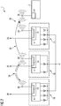
- the FIG 1 shows a schematic representation of an arrangement 1 for illuminating a rail vehicle according to the first embodiment.
- the arrangement 1 is shown as a circuit diagram and is intended to illustrate a connection of the relevant components of a rail vehicle.
- the arrangement 1 has a central control device 2 which is connected to a control system (not shown) and can be arranged in an area of a driver's cab.
- the arrangement 1 has several separate control devices 4, 6, 8.
- the separate control devices 4, 6, 8 each have an independent communication unit 10.
- the separate control devices 4, 6, 8 can be connected to one another and to the central control device 2 through the communication unit 10.
- the central control device 2 also has a communication unit 10. Information and commands can be exchanged through a communication link 12.
- the commands can be digital or analog control commands or regulation commands that trigger or report certain functions or operating states.
- the communication link 12 is a wired BUS system 12.
- the BUS system 12 does not connect every separate or decentralized control device 4, 6, 8 to the central control device 2.
- the separate control devices 4, 6, 8 are rather, connected in a series circuit through the BUS system 12. This means that the BUS system only has to be laid once along the required length and not for each individual control unit 4, 6, 8 separately and thus several times in parallel next to each other.
- Each separate control device 4, 6, 8 has a plurality of connected lighting means 14, 16, 18.
- the control devices 4, 6, 8 are designed integrally with the lighting means 14, 16, 18.
- the lighting means 14 are, for example, headlights, direction indicators or position lights and optionally switchable rear lights arranged at a front end of a rail vehicle.
- the lighting means 18 can be arranged analogously to the lighting means 14 at a rear end of a rail vehicle.
- the lighting means 16 can be arranged in an outside area of a rail vehicle and illuminate the surroundings of the rail vehicle in order to facilitate exit. Alternatively or in addition, the lighting means 16 can also be arranged within wagons of the rail vehicle and serve as interior lighting.
- Each of the separate control devices 4, 6, 8 is connected to an energy supply 20 independently of the BUS system 12. The separate control devices 4, 6, 8 can thus control the lighting means 14, 16, 18 as a function of or independently of a signal transmitted via the BUS system.
- the separate control devices 4, 6, 8 can switch the lighting means 14, 16, 18 to an emergency lighting state in the event of a missing signal.
- the separate control devices 4, 6, 8 can receive corresponding information from the central control device 2 and use the lighting as energy-saving as possible so that the rail vehicle is ready for operation more quickly.
- the central control device 2 can transmit an operating state of the rail vehicle, such as a direction of travel, a standstill, or a stop in a train station, via the BUS system 12.
- the separate control devices 4, 6, 8 can control the lighting means 14, 16, 18 and thus switch on, switch off, darken or lighten the lighting means 14, 16, 18 together or separately or make the lighting means 14, 16, 18 initiate.
- the separate control devices 4, 6, 8 at least one fuse 22.
- the fuse 22 is triggered if a short circuit or a defect occurs in the area of the respective separate control device 4, 6, 8 or the respective lighting means 14, 16, 18.
- the respective separate control units 4, 6, 8 can transmit information about the triggering of the fuse 22 and the location of the fuse 22 to the central control unit 2 and thus indirectly also to the control system of the rail vehicle.
- FIG.2 is a schematic representation of an arrangement 1 according to a second embodiment.
- the decentralized control devices 4, 6, 8 and the central control device 2 each have wireless communication units 24.
- Each wireless communication unit 24 has a radio antenna 26.
- the communication unit 24 can thus send and receive information by means of radio signals.
- the wireless connection 28 or wireless communication connection 28 can be established between the decentralized control devices 4, 6, 8 with one another.
- Each decentralized control device 4, 6, 8 can also separately establish a wireless connection 28 with the central control device 2.
- the wireless connection 28 to the central control device 2 can also be established indirectly via a control device 4, 6, 8 located in a radio path or adjacent.
- the communication units 24 of the control devices 4, 6, 8 can act as signal amplifiers.
- Information or commands can thus be sent from the central control device 2 to a decentralized control device 4, 6, 8. This can also be done over long distances, such as in long rail vehicles, without wired communication. In the opposite direction, information can also be transmitted serially via a number of control units 4, 6, 8. In this way, commands or information can be transmitted from one wireless communication unit 24 to an adjacent wireless communication unit 24, which in turn is transmitted to a next wireless communication unit 24 forwards commands or information. This process can continue until the information or commands can be received by the central control device 2.
Landscapes
- Engineering & Computer Science (AREA)
- Mechanical Engineering (AREA)
- Lighting Device Outwards From Vehicle And Optical Signal (AREA)
- Train Traffic Observation, Control, And Security (AREA)
- Electric Propulsion And Braking For Vehicles (AREA)
- Circuit Arrangement For Electric Light Sources In General (AREA)
Description
- Die Erfindung betrifft eine Anordnung zur Beleuchtung eines Schienenfahrzeuges, sowie ein Schienenfahrzeug mit einer derartigen Anordnung.
- Schienenfahrzeuge weisen ein Steuergerät zur Ansteuerung und Überwachung der Beleuchtung, insbesondere der Außenbeleuchtung, auf. Jedes Leuchtmittel ist dabei einzeln mit dem Steuergerät verbunden. Dies erfordert viel Einbauraum für die hierbei erforderlichen Komponenten und eine umfangreiche Verdrahtung über die gesamte Erstreckung des Schienenfahrzeugs, die einer erhöhten Fehleranfälligkeit unterliegt. Des Weiteren weist eine derartige über große Strecken zu verlegende Verdrahtung einen hohen Montageaufwand und eine nicht unerhebliche Masse an Kabeln auf. Ein Steuergerät ist unter anderem für die Ansteuerung und Überwachung der gesamten Beleuchtung zuständig. Bei Ausfall des Steuergerätes bedeutet dies einen kompletten Ausfall der Beleuchtung, so dass nur noch mittels Notschalter eine Notbeleuchtung aktiviert werden kann. Da das Steuergerät meist auch die Funktion einer Schnittstelle zur Leittechnik einnimmt, werden viele digitale Inputs und Outputs benötigt. Der Einbauraum in einem Führertisch eines Schienenfahrzeuges ist jedoch stark begrenzt. Daneben ist auch ein möglicher Einbauraum zur Verlegung von Kabeln im Bereich von Wänden und Decken in übrigen Bereichen des Schienenfahrzeuges beschränkt.
- Das Dokument
KR 2016 0085655 A - Aufgabe der Erfindung ist es eine Anordnung zur Beleuchtung eines Schienenfahrzeuges vorzuschlagen, welche die zuvor genannten Nachteile beseitigt und eine Beleuchtung eines Schienenfahrzeuges gewährleistet, die nur wenig Einbauraum benötigt und eine geringere Fehleranfälligkeit aufweist. Des Weiteren ist es Aufgabe der Erfindung ein Schienenfahrzeug mit einer derartigen Anordnung vorzuschlagen.
- Gelöst wird die Aufgabe durch den Gegenstand des unabhängigen Patentanspruchs 1 und durch den Gegenstand des unabhängigen Patentanspruchs 14. Vorteilhafte Ausgestaltungen der Erfindung sind Gegenstand von jeweils abhängigen Unteransprüchen.
- Erfindungsgemäß wird eine Anordnung zum Beleuchten eines Schienenfahrzeuges bereitgestellt, welche mindestens eine Energiequelle, mindestens ein Steuergerät, sowie mindestens ein Leuchtmittel aufweist. Die Energiequelle ist mit dem mindestens einen Steuergerät über mindestens eine elektrische Leitung verbunden. Das Steuergerät wiederum ist über eine elektrische Leitung mit dem mindestens einen Leuchtmittel verbunden, wobei jedes Leuchtmittel jeweils mindestens ein benachbartes Steuergerät aufweist, und wobei das Steuergerät und das Leuchtmittel integral ausgeführt sind.
- Durch die Anordnung, bei der je ein Steuergerät jeweils einen Leuchtmittel überwacht und ansteuert, kann auf eine aufwändige Verkabelung zu einem zentralen Steuergerät zur Steuerung der Beleuchtung verzichtet werden. Der Begriff Verkabelung schließt dabei nicht nur elektrische Leitungen, sondern auch die zahlreichen Klemmen und Stecker ein, die für den Anschluss jedes Leuchtmittels an ein zentrales Steuergerät notwendig sind. Vorzugsweise wird die vorgeschlagene Anordnung für die Beleuchtung einer Lokomotive, insbesondere deren Außenbeleuchtung verwendet, wobei auch eine Verwendung für die Innenbeleuchtung oder andere Verbraucher wie beispielsweise Türen oder Ähnliches denkbar sind. Durch die Reduzierung der für die Beleuchtung notwendigen Verkabelung kann ein Einbauraum beispielsweise im Führertisch der Lokomotive eingespart werden, welche nur in begrenztem Maße vorhanden ist, so dass mehr Einbauraum für andere Systeme zur Verfügung steht. Aufgrund der geringeren Anzahl an benötigten Komponenten sowie der streckenmäßig um ein Vielfaches kürzeren Verkabelung ist die Anordnung deutlich weniger fehleranfällig und weniger wartungsintensiv. Des Weiteren kann durch eine Verringerung der Anzahl an Kabeln und Anschlüssen ein Montageaufwand reduziert werden. Hierdurch kann die Herstellung oder Reparatur eines Schienenfahrzeuges beschleunigt werden.
- Gemäß der Erfindung sind das Steuergerät und das Leuchtmittel integral ausgeführt. Dabei können das Steuergerät und das Leuchtmittel ineinander oder miteinander verkapselt, verschweißt, verschraubt oder vergossen sein. Das hierdurch gebildete Modul ermöglicht eine einfache Montage und das Entfallen einer separaten und aufwändigen Verkabelung des Steuergerätes mit dem Leuchtmittel. Im Falle eines Defekts kann das gesamte Modul schnell und einfach ersetzt werden. Durch die verringerte Anzahl an Komponenten können Wartungs- und Reparaturaufwand reduziert werden, wodurch die Standzeiten von Schienenfahrzeugen insgesamt stark verkürzt werden können. Das mindestens eine Leuchtmittel kann hierbei auch auswechselbar mit dem Steuergerät verbunden sein.
- Gemäß einem Ausführungsbeispiel der Anordnung weist das mindestens eine Steuergerät eine Schnittstelle zu einer Leittechnik des Schienenfahrzeugs auf. Hierdurch kann das Steuergerät an die Steuerung des Schienenfahrzeuges direkt oder indirekt angeschlossen werden. Dies ermöglicht eine Informationsübertragung, so dass beispielsweise ein Ausfall eines Leuchtmittels von der Führerkabine aus erkennbar ist. Zusätzlich oder alternativ kann der Betriebsmodus (beispielsweise AN oder AUS, sowie eine mögliche Dimmfunktion) des Leuchtmittels von der Führerkabine eingesehen und gesteuert werden. Die Informationen können dem Fahrzeugführer beispielsweise in Form von analogen oder digitalen Anzeigen oder Lichtsignalen übermittelt werden. Zusätzlich kann die Leittechnik eine zusätzliche Überwachungseinrichtung aufweisen, die zwecks Wartung oder Reparatur Zustände sämtlicher Steuergeräte und damit auch aller Leuchtmittel auflisten und analysieren kann. Vorteilhafterweise kann die Leittechnik eine zusätzliche Schnittstelle zum Verbinden von Analysewerkzeugen, wie beispielsweise mit entsprechender Software ausgestattete Notebooks, Computer oder Prüfstände aufweisen.
- Nach einem weiteren Ausführungsbeispiel der Anordnung zur Beleuchtung eines Schienenfahrzeuges weist die Leittechnik mindestens ein zentrales Steuergerät auf. Jedes Leuchtmittel kann somit über das jeweilige, integral oder benachbart angeordnete Steuergerät mit einem zentralen Steuergerät verbunden sein und von dem zentralen Steuergerät koordiniert werden. Das zentrale Steuergerät kann mit der Leitzentrale kommunizieren und dabei beispielsweise in der Nähe oder in einer Fahrerkabine angeordnet sein. Durch eine derartige Anordnung und die Verwendung eines integral mit einem Leuchtmittel verbundenem Steuergerät können die benötigten Mengen an Verkabelung, inklusive Klemmen, Leitungen und Steckern stark reduziert werden, da eine aufwändige Verkabelung für jedes einzelnen Leuchtmittel mit einem zentralen Steuergerät, welches gleichzeitig eine Schnittstelle für zur Leittechnik darstellt, entfällt. Darüber hinaus kann durch die dezentrale Anordnung der benachbarten oder in die Leuchtmittel integrierten Steuergeräte die Dimensionierung des zentralen Steuergerätes, welches meist im räumlich stark begrenztem Führertisch bzw. der Führerkabine angeordnet ist, wesentlich reduziert werden.
- Gemäß einem weiteren Ausführungsbeispiel der Anordnung weist das mindestens eine Steuergerät des mindestens einen Leuchtmittels und das mindestens eine Steuergerät der Leittechnik drahtlose oder drahtgebundene Kommunikationsverbindung auf. Jedes Steuergerät kann dabei eine drahtlose Kommunikationsschnittstelle bzw. Kommunikationseinheit aufweisen. Mit Hilfe der Kommunikationseinheit können Informationen und Befehle übertragen werden. Es könnten beispielsweise Funk, Bluetooth, WLAN, Infrarotverbindung und derartige Übertragungstechnik verwendet werden. Hierdurch kann die Verkabelung zwecks Informationsübertragung und Steuerung bzw. Regelung der Leuchtmittel komplett entfallen. Vielmehr können die jeweiligen Steuergeräte direkt mit einem zentralen Steuergerät drahtlos kommunizieren oder über jeweils andere Steuergeräte, die alternativ oder zusätzlich als Repeater dienen, mit dem zentralen Steuergerät oder Leitzentrale kommunizieren. Hierbei können auch die vorhandenen dezentralen Steuergeräte mit einer drahtlosen Kommunikationsschnittstelle als Repeater die Informationen oder Befehle anderer Steuergeräte weiterleiten. Vorteilhafterweise können die dezentralen Steuergeräte und das mindestens eine zentrale Steuergerät gemeinsam und separat untereinander kommunizieren. Eine Verkabelung wird somit ausschließlich für die direkte Stromanbindung benötigt und kann im Vergleich zu einem Anbindungsaufwand eines kabelgebundenen bzw. drahtgebundenen Informationsübertragungssystems in deutlich reduzierter Form gestaltet werden. Eine drahtgebundene Kommunikationsverbindung oder Kommunikationsübertragung kann beispielsweise in Form eines BUS-Systems, wie beispielsweise CAN (Controller Area Network)-BUS-System, ausgeführt sein. Alternativ kann eine Kommunikationsübertragung über Lichtwellenleiter in Form von digitalen Lichtsignalen erfolgen.
- Gemäß einem weiteren Ausführungsbeispiel der Anordnung weist die drahtgebundene oder drahtlose Kommunikationsverbindung eine Kodierung auf. Dabei werden eindeutige Befehle durch eine definierte Kodierung der Daten übertragen. Dies kann die Sicherheit der übertragenen Daten erhöhen, so dass die Information vor Manipulation durch Dritte geschützt werden können. Des Weiteren können die zu übertragenen Befehle und Informationen derart digital oder analog umgewandelt werden, dass im Falle einer drahtgebundenen Kommunikationsverbindung die Anzahl an elektrischen Leitungen minimiert wird.
- Nach einem weiteren Ausführungsbeispiel der Anordnung sind die elektrischen Leitungen als Bus-System ausgeführt. Die jeweiligen Steuergeräte können dabei auch an bestehende BUS-Systeme angebunden werden und drahtgebunden mit der Leittechnik kommunizieren.
- Gemäß einem weiteren Ausführungsbeispiel der Anordnung überwacht jedes Steuergerät mindestens ein Leuchtmittel. Jedem Leuchtmittel wird ein Steuergerät zugeordnet, das ausschließlich für die Überwachung und Ansteuerung des zugeordneten Leuchtmittels zuständig ist. Die jeweilig am den Leuchtmitteln angeordneten Steuergeräte können kleiner bzw. leistungsschwächer ausgeführt sein als beispielsweise ein zentrales Steuergerät. Dies ermöglicht, dass die Steuergeräte somit direkt neben, in oder in der Nähe des Leuchtmittels angeordnet sein können, wodurch weniger Kabellänge und Komponenten wie Klemmen und Stecker im Vergleich zu einer Anordnung mit einem zentralen Steuergerät notwendig sind.
- Gemäß einem weiteren Ausführungsbeispiel der Anordnung kann das Leuchtmittel aus mehreren Lichtquellen bestehen. Durch das Vorhandensein einer Redundanz durch mehrere Lichtquellen kann die Betriebssicherheit erhöht werden. Bei einem Ausfall einer Lichtquelle eines Leuchtmittels kann das Schienenfahrzeug weiterhin durch die verbleibenden Lichtquellen in dem Leuchtmittel, eventuell bei leichten Einbußen in der Helligkeit, beleuchtet werden, ohne dass direkt auf einen Notbeleuchtung umgeschaltet werden muss.
- Gemäß einem weiteren Ausführungsbeispiel der Anordnung ist das Leuchtmittel in LED-Technik, Xenon, halogen HDI-Technik ausgeführt. Hierdurch bieten sich sehr vielseitige Einsatzmöglichkeiten. LED-Leuchtmittel sind beispielsweise sehr sparsam und langlebig. Xenon-Lampen können sehr leistungsfähig sein um beispielsweise weg weitreichend zu beleuchten und eignen sich gut als Fahrtrichtungsbeleuchtung. Darüber hinaus sind Kombinationen von mehreren unterschiedlichen Leuchtmittelarten in einem oder mehreren Leuchtmitteln entsprechend dem Einsatzbereich möglich. LEDs können beispielsweise derart mit einem dezentralen Steuergerät verbunden sein, dass ein Auswechseln nicht möglich ist. Beispielsweise können beide Bauelemente miteinander vergossen oder verklebt sein. Alternativ können Leuchtmittel bzw. einzelne Lichtquellen in ein dezentrales Steuergerät integriert sein. Hierdurch kann ein verbesserter Schutz vor Umwelteinflüssen und eine einfachere Herstellung realisiert werden.
- Nach einem weiteren Ausführungsbeispiel der Anordnung zum Beleuchten eines Schienenfahrzeuges weist jedes Leuchtmittel eine eigene Sicherung auf. Bei einem Ausfall der Beleuchtung kann die Suche der Fehlerquelle hierdurch wesentlich eingegrenzt und damit verkürzt werden, da man die Sicherungen den jeweiligen Leuchtmitteln zuordnen kann. Dies erhöht zusätzlich die Betriebssicherheit der Beleuchtung des Schienenfahrzeuges.
- Gemäß einem weiteren Ausführungsbeispiel der Anordnung ist die Sicherung des Leuchtmittels manuell oder automatisch betätigbar. Die Sicherung kann beispielsweise als Sicherungsautomat ausgeführt sein, der selbstständig bei zu hoher Belastung aktivierbar ist. Ein derartiger Sicherungsautomat kann beispielsweise direkt oder indirekt per Schalter oder über Fernsteuerung wieder deaktivierbar sein.
- Gemäß einem weiteren Ausführungsbeispiel der Anordnung ist das mindestens eine Leuchtmittel durch das Steuergerät in mindestens einen Betriebszustand versetzbar. Jeweils abhängig von verschiedenen Situationen können unterschiedliche Betriebszustände bzw. Lichtsignale für den sicheren Betrieb eines Schienenfahrzeugs notwendig sein. Beispielsweise kann beim Rückwärtsfahren eines Schienenfahrzeuges eine andere Beleuchtung erforderlich sein als bei einer vorwärts gerichteten Fahrtrichtung. Dies kann insbesondere bei Schienenfahrzeugen mit an beiden Enden angeordneten Triebwagen von Vorteil sein. Vorteilhafterweise kann das Steuergerät das Leuchtmittel beispielsweise dimmen, anschalten oder ausschalten. Darüber hinaus sind weitere Signale wie Blinken oder ähnliches möglich. Das dezentrale Steuergerät kann beispielsweise durch eine direkte bzw. aktive Ansteuerung oder automatisch durch beispielsweise einen identifizierten Betriebszustand des Schienenfahrzeuges einen Betriebszustand des Leuchtmittels bestimmen.
- Gemäß einem weiteren Ausführungsbeispiel der Anordnung zum Beleuchten eines Schienenfahrzeuges ist ein Betriebszustand beispielsweise ein Notbeleuchtungszustand, Tagbeleuchtungszustand oder Nachtbeleuchtungszustand. Es sind verschiedene Beleuchtungsmodi möglich die je nach Betriebsart bzw. Tageszeit- oder Helligkeitsanforderungen die Beleuchtung des Schienenfahrzeuges unterschiedlich regeln. Die Beleuchtungsmodi können dabei mit dem Betriebsmodus des Schienenfahrzeuges koppelbar sein. Dabei kann eine automatische Anpassung der Beleuchtung an die jeweiligen Außenbedingungen des Schienenfahrzeuges erfolgen. Durch Helligkeitssensoren könnte die Helligkeit im Umfeld des Schienenfahrzeuges erfasst und als Signal über das zentrale Steuergerät an die separaten bzw. dezentralen Steuergeräte der jeweiligen Leuchtmittel weitergeleitet werden. Die Steuergeräte können anschließend das Signal in einen Betriebszustand der Leuchtmittel umsetzen. Alternativ oder zusätzlich können auch andere Sensoren wie Temperatursensoren oder Geschwindigkeitssensoren zusätzliche Informationen ermitteln, die anschließend von den Steuergeräten verarbeitet werden. So könnte beim Einfahren in einen Tunnel die Leuchtmittel des Schienenfahrzeuges automatisch angehen oder ihr Lichtsignale verstärken und beim Verlassen des Tunnels wieder automatisch abgedimmt werden.
- Nach einem weiteren Aspekt der Erfindung wird ein Schienenfahrzeug mit mindestens einem angetriebenen oder nicht angetriebenen Wagen mit einer Anordnung zum Beleuchten eines Schienenfahrzeuges bereitgestellt. Die Anordnung weist mindestens eine Energiequelle, mindestens ein Steuergerät, sowie mindestens ein Leuchtmittel auf. Die Energiequelle ist mit dem mindestens einen Steuergerät über mindestens eine elektrische Leitung verbunden. Das Steuergerät wiederum ist über eine elektrische Leitung mit dem mindestens einen Leuchtmittel verbunden, wobei jedes Leuchtmittel mindestens ein benachbartes Steuergerät aufweist.
- Die oben beschriebenen Eigenschaften, Merkmale und Vorteile dieser Erfindung sowie die Art und Weise, wie diese erreicht werden, werden klarer und deutlicher verständlich durch die Erläuterung der folgenden stark vereinfachten schematischen Darstellungen bevorzugter Ausführungsbeispiele. Hierbei zeigen
- FIG 1
- eine schematische Darstellung einer Anordnung gemäß einem ersten Ausführungsbeispiel und
- FIG 2
- eine schematische Darstellung einer Anordnung gemäß einem zweiten Ausführungsbeispiel.
- In den Figuren weisen dieselben konstruktiven Elemente jeweils dieselben Bezugsziffern auf.
- Die
FIG 1 zeigt eine schematische Darstellung einer Anordnung 1 zur Beleuchtung eines Schienenfahrzeuges gemäß dem ersten Ausführungsbeispiel. Die Anordnung 1 ist als ein Schaltdiagramm dargestellt und soll eine Anbindung der relevanten Komponenten eines Schienenfahrzeuges verdeutlichen. Die Anordnung 1 weist ein zentrales Steuergerät 2 auf, welches mit einer nicht dargestellten Leittechnik verbunden ist und in einem Bereich einer Führerkabine angeordnet sein kann. Des Weiteren weist die Anordnung 1 mehrere separate Steuergeräte 4, 6, 8 auf. Die separaten Steuergeräte 4, 6, 8 weisen jeweils eine eigenständige Kommunikationseinheit 10 auf. Durch die Kommunikationseinheit 10 können die separaten Steuergeräte 4, 6, 8 untereinander und mit dem zentralen Steuergerät 2 verbunden werden. Das zentrale Steuergerät 2 weist ebenfalls eine Kommunikationseinheit 10 auf. Durch eine Kommunikationsverbindung 12 lassen sich Informationen und Befehle austauschen. Die Befehle können hierbei digitale oder analoge Steuerbefehle oder Regelungsbefehle sein, die bestimmte Funktionen oder Betriebszustände auslösen oder melden. Die Kommunikationsverbindung 12 ist gemäß dem Ausführungsbeispiel ein drahtgebundenes BUS-System 12. Das BUS-System 12 verbindet gemäß dem Ausführungsbeispiel nicht jedes separate bzw. dezentrale Steuergerät 4, 6, 8 mit dem zentralen Steuergerät 2. Die separaten Steuergeräte 4, 6, 8 sind vielmehr in einer Reihenschaltung durch das BUS-System 12 verbunden. Hierdurch muss das BUS-System lediglich einmal entlang der benötigten Länge verlegt werden und nicht für jedes einzelne Steuergerät 4, 6, 8 separat und somit mehrfach parallel nebeneinander. Jedes separate Steuergerät 4, 6, 8 weist mehrere angeschlossene Leuchtmittel 14, 16, 18 auf. Die Steuergeräte 4, 6,8 sind hierbei integral mit den Leuchtmitteln 14, 16, 18 ausgeführt. Die Leuchtmittel 14 sind beispielsweise an einem vorderen Ende eines Schienenfahrzeuges angeordnete Scheinwerfer, Richtungsanzeiger bzw. Positionsleuchten und wahlweise zuschaltbare Rückleuchten. Die Leuchtmittel 18 können analog zu den Leuchtmittel 14 an einem hinteren Ende eines Schienenfahrzeuges angeordnet sein. Die Leuchtmittel 16 können in einem Außenbereich eines Schienenfahrzeuges angeordnet sein und eine Umgebung des Schienenfahrzeuges beleuchten um einen Ausstieg zu erleichtern. Alternativ oder zusätzlich können die Leuchtmittel 16 auch innerhalb von Wagons des Schienenfahrzeuges angeordnet sein und als Innenbeleuchtung dienen. Jedes der separaten Steuergeräte 4, 6, 8 ist unabhängig von dem BUS-System 12 an eine Energieversorgung 20 angebunden. Die separaten Steuergeräte 4, 6, 8 können somit abhängig oder unabhängig von einem über das BUS-System übermittelten Signal die Leuchtmittel 14, 16, 18 ansteuern. Beispielsweise können die separaten Steuergeräte 4, 6, 8 die Leuchtmittel 14, 16, 18 bei einem fehlenden Signal in einen Notbeleuchtungszustand versetzen. Bei einem Start des Schienenfahrzeuges oder während einer Startphase können die separaten Steuergeräte 4, 6, 8 von dem zentralen Steuergerät 2 entsprechende Informationen erhalten und die Beleuchtung möglichst stromsparend einsetzen, sodass das Schienenfahrzeug schneller betriebsbereit wird. Des Weiteren kann das zentrale Steuergerät 2 einen Betriebszustand des Schienenfahrzeuges wie beispielsweise eine Fahrtrichtung, einen Stillstand, oder einen Halt in einem Bahnhof über das BUS-System 12 übermitteln. Abhängig von dem Betriebszustand des Schienenfahrzeuges können die separaten Steuergeräte 4, 6, 8 die Leuchtmittel 14, 16, 18 ansteuern und somit die Leuchtmittel 14, 16, 18 gemeinsam oder separat einschalten, ausschalten, abdunkeln bzw. erhellen oder ein Blinken der Leuchtmittel 14, 16, 18 einleiten. Damit eine Betriebssicherheit der separaten Steuergeräte 4, 6, 8 gewährleistet werden kann weisen die separaten Steuergeräte 4, 6, 8 mindestens eine Sicherung 22 auf. Die Sicherung 22 wird ausgelöst, wenn im Bereich des jeweiligen separaten Steuergerätes 4, 6, 8 oder der jeweiligen Leuchtmittel 14, 16, 18 ein Kurzschluss oder ein Defekt auftritt. Abhängig von einem Auslösen der jeweiligen Sicherung 22 können die jeweiligen separaten Steuergeräte 4, 6, 8 eine Information über das Auslösen der Sicherung 22 und den Ort der Sicherung 22 an das zentrale Steuergerät 2 und somit indirekt auch an die Leittechnik des Schienenfahrzeuges übermitteln. - In
FIG.2 ist eine schematische Darstellung einer Anordnung 1 gemäß einem zweiten Ausführungsbeispiel dargestellt. Im Unterschied zu der Anordnung 1 gemäß dem ersten Ausführungsbeispiel weisen die dezentralen Steuergeräte 4, 6, 8 und das zentrale Steuergerät 2 jeweils drahtlose Kommunikationseinheiten 24 auf. Jede drahtlose Kommunikationseinheit 24 weist eine Funkantenne 26 auf. Somit kann die Kommunikationseinheit 24 mittels Funksignalen Informationen senden und empfangen. Die drahtlose Verbindung 28 bzw. drahtlose Kommunikationsverbindung 28 kann hierbei zwischen den dezentralen Steuergeräten 4, 6, 8 untereinander hergestellt werden. Jedes dezentrale Steuergerät 4, 6, 8 kann hierbei auch separat eine drahtlose Verbindung 28 mit dem zentralen Steuergerät 2 herstellen. Eine Herstellung der drahtlosen Verbindung 28 mit dem zentralen Steuergerät 2 kann hierbei auch indirekt über ein in einem Funkweg liegendes oder benachbartes Steuergerät 4, 6, 8 erfolgen. Hierbei können die Kommunikationseinheiten 24 der Steuergeräte 4, 6, 8 als Signalverstärker agieren. So können Informationen oder Befehle von dem zentralen Steuergerät 2 zu einem dezentralen Steuergerät 4, 6, 8 hin gesendet werden. Dies kann auch über lange Strecken wie beispielsweise bei langen Schienenfahrzeugen ohne drahtgebundene Kommunikation erfolgen. In umgekehrter Richtung kann ebenfalls die Informationsübertragung über mehrere Steuergeräte 4, 6, 8 hinweg seriell realisiert werden. So können Befehle oder Informationen von einer drahtlosen Kommunikationseinheit 24 zu einer benachbarten drahtlosen Kommunikationseinheit 24 übertragen werden, die wiederum zu einer nächsten drahtlosen Kommunikationseinheit 24 die Befehle oder Informationen weiterleitet. Dieser Vorgang kann solange erfolgen, bis die Informationen bzw. Befehle von dem zentralen Steuergerät 2 empfangen werden können. - Obwohl die Erfindung im Detail durch die bevorzugten Ausführungsbeispiele näher illustriert und beschrieben wurde, so ist die Erfindung nicht durch die offenbarten Beispiele eingeschränkt und andere Variationen können vom Fachmann im Rahmen der Ansprüche abgeleitet werden, ohne den Schutzumfang der Erfindung zu verlassen.
Claims (14)
- Anordnung (1) zur Beleuchtung eines Schienenfahrzeuges, aufweisend mindestens eine Energiequelle (20), mindestens ein Steuergerät (4, 6, 8), mindestens ein Leuchtmittel (14, 16, 18), mindestens eine elektrische Leitung zum Verbinden der Energiequelle (20) mit dem mindestens einen Steuergerät (4, 6, 8) und eine elektrische Leitung zum Verbinden des Steuergerätes (4, 6, 8) mit dem mindestens einem Leuchtmittel (14, 16, 18),- bei der jedes Leuchtmittel (14, 16, 18) jeweils mindestens ein benachbartes Steuergerät (4, 6, 8) aufweist, und- bei der das Steuergerät (4, 6, 8) und das Leuchtmittel (14, 16, 18) integral ausgeführt sind.
- Anordnung nach Anspruch 1, bei der das mindestens eine Steuergerät (4, 6, 8) eine Schnittstelle (10,24) zu einer Leittechnik des Schienenfahrzeugs aufweist.
- Anordnung nach einem der Ansprüche 1 bis 2, bei der die Leittechnik mindestens ein zentrales Steuergerät (2) aufweist
- Anordnung nach einem der Ansprüche 1 bis 3, bei der das mindestens eine Steuergerät (4, 6, 8) des mindestens einen Leuchtmittels (14, 16, 18) und das mindestens eine Steuergerät (2) der Leittechnik drahtlose oder drahtgebundene Kommunikationsverbindung (12, 28) aufweisen.
- Anordnung nach einem der Ansprüche 1 bis 4, bei der die drahtgebundene oder die drahtlose Kommunikationsverbindung (12, 28) eine Kodierung aufweist.
- Anordnung nach einem der Ansprüche 1 bis 5, bei der die elektrischen Leitungen als Bus-System ausgeführt sind.
- Anordnung nach einem der Ansprüche 1 bis 6, bei der jedes Steuergerät (4, 6, 8) mindestens ein Leuchtmittel (14, 16, 18) überwacht.
- Anordnung nach einem der Ansprüche 1 bis 7, bei der das mindestens eine Leuchtmittel (14, 16, 18) eine oder mehrere Lichtquellen aufweist.
- Anordnung nach einem der Ansprüche 1 bis 8, bei der das mindestens eine Leuchtmittel (14, 16, 18) in LED-, Xenon- oder Halogen-Technik ausgeführt ist.
- Anordnung nach einem der Ansprüche 1 bis 9, bei der jedes Leuchtmittel (14, 16, 18) eine eigene Sicherung (22) aufweist.
- Anordnung nach Anspruch 10, bei der die Sicherung (22) manuell oder automatisch betätigbar ist.
- Anordnung nach einem der Ansprüche 1 bis 11, bei der das mindestens eine Leuchtmittel (14, 16, 18) durch das Steuergerät (4, 6, 8) in mindestens einen Betriebszustand versetzbar ist.
- Anordnung nach Anspruch 12, bei der ein Betriebszustand ein Notbeleuchtungszustand, Tagbeleuchtungszustand oder Nachtbeleuchtungszustand ist.
- Schienenfahrzeug mit einer Anordnung (1) nach einem der vorhergehenden Ansprüche, mit mindestens einem angetriebenen oder nicht-angetriebenen Wagen.
Applications Claiming Priority (2)
| Application Number | Priority Date | Filing Date | Title |
|---|---|---|---|
| DE102017203018.6A DE102017203018A1 (de) | 2017-02-24 | 2017-02-24 | Anordnung zur Beleuchtung eines Schienenfahrzeuges und Schienenfahrzeug |
| PCT/EP2017/084714 WO2018153538A1 (de) | 2017-02-24 | 2017-12-28 | Anordnung zur beleuchtung eines schienenfahrzeuges und schienenfahrzeug |
Publications (2)
| Publication Number | Publication Date |
|---|---|
| EP3571106A1 EP3571106A1 (de) | 2019-11-27 |
| EP3571106B1 true EP3571106B1 (de) | 2020-12-09 |
Family
ID=60997446
Family Applications (1)
| Application Number | Title | Priority Date | Filing Date |
|---|---|---|---|
| EP17829991.3A Active EP3571106B1 (de) | 2017-02-24 | 2017-12-28 | Anordnung zur beleuchtung eines schienenfahrzeuges und schienenfahrzeug |
Country Status (5)
| Country | Link |
|---|---|
| US (1) | US11130505B2 (de) |
| EP (1) | EP3571106B1 (de) |
| DE (1) | DE102017203018A1 (de) |
| ES (1) | ES2864250T3 (de) |
| WO (1) | WO2018153538A1 (de) |
Families Citing this family (1)
| Publication number | Priority date | Publication date | Assignee | Title |
|---|---|---|---|---|
| DE102018212768A1 (de) * | 2018-07-31 | 2020-02-06 | Siemens Aktiengesellschaft | Verfahren zum Erzeugen einer Bewegungsinformation |
Family Cites Families (18)
| Publication number | Priority date | Publication date | Assignee | Title |
|---|---|---|---|---|
| DE9318296U1 (de) | 1993-11-25 | 1994-02-03 | Fahrzeugausrüstung Berlin GmbH, 10243 Berlin | Schlußlichtkontrollanzeige insbesondere für Schienenfahrzeuge |
| KR0140251B1 (ko) * | 1995-12-11 | 1998-06-01 | 최재환 | 자동차의 정.동적상태 표시장치 및 그 제어방법 |
| JP5144160B2 (ja) * | 2007-07-26 | 2013-02-13 | パナソニック株式会社 | 車載用負荷制御装置、車載用前照灯装置、および車載用尾灯装置 |
| EP2386263B1 (de) | 2010-05-11 | 2014-02-26 | Bien-Air Holding SA | Beleuchtungsmodul mit Elektrolumineszenzdioden für chirurgisches oder zahntechnisches Handstück |
| GB201015393D0 (en) | 2010-09-15 | 2010-10-27 | Saf T Glo Ltd | Lighting systems |
| NO2694352T3 (de) * | 2011-04-05 | 2018-07-21 | ||
| US8890411B2 (en) * | 2011-10-14 | 2014-11-18 | Control Solutions LLC | Computer controlled configurable lighting system for modular vehicle lights |
| DE102012005480A1 (de) * | 2012-03-19 | 2013-09-19 | SBF Spezialleuchten GmbH | Außenlichtanordnung für ein Schienenfahrzeug |
| EP2850919B1 (de) | 2012-05-15 | 2017-08-16 | Philips Lighting Holding B.V. | Beleuchtungssteuerung und beleuchtungssystem |
| DE102012011075A1 (de) | 2012-06-04 | 2013-12-05 | SBF Spezialleuchten GmbH | Beleuchtungssystem und Verfahren zum Betrieb eines Beleuchtungssystems, insbesondere für ein Schienenfahrzeug |
| DE102012017656A1 (de) | 2012-09-06 | 2014-03-06 | SBF Spezialleuchten GmbH | Leuchte für Fahrzeuge, insbesondere Schienenfahrzeuge |
| US8941311B2 (en) | 2013-04-09 | 2015-01-27 | Bombardier Transportation Gmbh | Control of the intensity of a LED lighting system |
| DE102013219121A1 (de) * | 2013-09-24 | 2015-03-26 | Siemens Aktiengesellschaft | Multifunktionales Mittellicht für ein Schienenfahrzeug |
| WO2015198375A1 (ja) | 2014-06-23 | 2015-12-30 | レシップホールディングス株式会社 | 照明装置 |
| US9386648B2 (en) * | 2014-12-05 | 2016-07-05 | Abl Ip Holding, Llc | Systems, apparatus, and methods for converting a bi-level lighting system to a dimmable lighting system |
| KR101672184B1 (ko) * | 2015-01-08 | 2016-11-03 | 한국철도공사 | 디젤기관차의 led 전조등용 전원공급장치 |
| RU159043U1 (ru) | 2015-02-16 | 2016-01-27 | Общество с ограниченной ответственностью Горнтрейд | Устройство управления приводом стеклоочистителя |
| KR102546654B1 (ko) * | 2015-12-11 | 2023-06-23 | 삼성전자주식회사 | 조명 시스템, 조명 장치 및 그 제어 방법 |
-
2017
- 2017-02-24 DE DE102017203018.6A patent/DE102017203018A1/de not_active Ceased
- 2017-12-28 WO PCT/EP2017/084714 patent/WO2018153538A1/de not_active Ceased
- 2017-12-28 ES ES17829991T patent/ES2864250T3/es active Active
- 2017-12-28 US US16/488,763 patent/US11130505B2/en not_active Expired - Fee Related
- 2017-12-28 EP EP17829991.3A patent/EP3571106B1/de active Active
Non-Patent Citations (1)
| Title |
|---|
| None * |
Also Published As
| Publication number | Publication date |
|---|---|
| US11130505B2 (en) | 2021-09-28 |
| DE102017203018A1 (de) | 2018-08-30 |
| ES2864250T3 (es) | 2021-10-13 |
| WO2018153538A1 (de) | 2018-08-30 |
| US20210139055A1 (en) | 2021-05-13 |
| EP3571106A1 (de) | 2019-11-27 |
Similar Documents
| Publication | Publication Date | Title |
|---|---|---|
| DE102014214228B4 (de) | Schienenfahrzeug | |
| EP2420427B2 (de) | Verfahren und Vorrichtung zur Überwachung eines Betriebszustands einer Kupplungsvorrichtung | |
| DE102013020177A1 (de) | Kraftfahrzeug | |
| EP2555958A1 (de) | Steuernetzwerk für ein schienenfahrzeug | |
| EP3509923B1 (de) | Mehrteilig ausgeführte bremsregelung | |
| EP1702802B1 (de) | Steuerungsvorrichtung für Anhänger und Fahrradträger | |
| EP3036146B1 (de) | Betrieb eines schienenfahrzeugs | |
| DE102010014333A1 (de) | Verfahren und Vorrichtung zur Bestimmung der Zuglänge mehrerer gekuppelter Triebfahrzeuge | |
| EP3571106B1 (de) | Anordnung zur beleuchtung eines schienenfahrzeuges und schienenfahrzeug | |
| WO2011161156A1 (de) | Flurförderzeug mit einer arbeitsleuchte und verfahren zum ein- und ausschalten | |
| DE102004056123A1 (de) | Nutzfahrzeug | |
| EP2974548B1 (de) | Leuchtvorrichtung mit zwei schnittstellen | |
| WO2020049115A1 (de) | Fahrzeugleuchte | |
| DE202011100493U1 (de) | Schaltungsanordnung in einem Zugfahrzeug sowie einem Anhänger | |
| AT501117B1 (de) | Kommunikationssystem | |
| DE202005017151U1 (de) | Steuerungsvorrichtung für Anhänger und Fahrradträger | |
| EP2804798B1 (de) | Verfahren zum steuern, sichern und/oder überwachen des schienengebundenen verkehrs sowie betriebsleittechnisches system | |
| EP3324710B1 (de) | Verfahren zum betreiben einer beleuchtungseinrichtung und beleuchtungseinrichtung | |
| EP3969346B1 (de) | Anzeigesystem für ein schienenfahrzeug und verfahren | |
| WO2020052977A1 (de) | Verfahren und system zum betreiben eines spurgebundenen fahrzeugs in einem von einer begleitperson begleiteten fahrerlosen betrieb | |
| DE69737556T2 (de) | Anordnung zum agieren auf eine anzahl von sensorsignalen und zur steuerung einer anzahl von kraftfahrzeug-betätigungs-vorrichtungen, und steuergerät | |
| EP2671746B1 (de) | Beleuchtungssystem und Verfahren zum Betrieb eines Beleuchtungssystems, insbesondere für ein Schienenfahrzeug | |
| AT401980B (de) | Steuerungsvorrichtung für zumindest zwei in einem schienenfahrzeug angeordnete elektrische verbraucher | |
| EP4699894A1 (de) | Schaltvorrichtung für eine schienenfahrzeugeinheit zur ansteuerung eines kupplungsvorgangs sowie schienenfahrzeugeinheit und schienenfahrzeugverband | |
| DE102008004687A1 (de) | Signallübertragungssystem in einem Kraftfahrzeug mit einem Anhänger |
Legal Events
| Date | Code | Title | Description |
|---|---|---|---|
| STAA | Information on the status of an ep patent application or granted ep patent |
Free format text: STATUS: UNKNOWN |
|
| STAA | Information on the status of an ep patent application or granted ep patent |
Free format text: STATUS: THE INTERNATIONAL PUBLICATION HAS BEEN MADE |
|
| PUAI | Public reference made under article 153(3) epc to a published international application that has entered the european phase |
Free format text: ORIGINAL CODE: 0009012 |
|
| STAA | Information on the status of an ep patent application or granted ep patent |
Free format text: STATUS: REQUEST FOR EXAMINATION WAS MADE |
|
| 17P | Request for examination filed |
Effective date: 20190820 |
|
| AK | Designated contracting states |
Kind code of ref document: A1 Designated state(s): AL AT BE BG CH CY CZ DE DK EE ES FI FR GB GR HR HU IE IS IT LI LT LU LV MC MK MT NL NO PL PT RO RS SE SI SK SM TR |
|
| AX | Request for extension of the european patent |
Extension state: BA ME |
|
| DAV | Request for validation of the european patent (deleted) | ||
| DAX | Request for extension of the european patent (deleted) | ||
| GRAP | Despatch of communication of intention to grant a patent |
Free format text: ORIGINAL CODE: EPIDOSNIGR1 |
|
| STAA | Information on the status of an ep patent application or granted ep patent |
Free format text: STATUS: GRANT OF PATENT IS INTENDED |
|
| INTG | Intention to grant announced |
Effective date: 20200807 |
|
| GRAS | Grant fee paid |
Free format text: ORIGINAL CODE: EPIDOSNIGR3 |
|
| GRAA | (expected) grant |
Free format text: ORIGINAL CODE: 0009210 |
|
| STAA | Information on the status of an ep patent application or granted ep patent |
Free format text: STATUS: THE PATENT HAS BEEN GRANTED |
|
| AK | Designated contracting states |
Kind code of ref document: B1 Designated state(s): AL AT BE BG CH CY CZ DE DK EE ES FI FR GB GR HR HU IE IS IT LI LT LU LV MC MK MT NL NO PL PT RO RS SE SI SK SM TR |
|
| REG | Reference to a national code |
Ref country code: GB Ref legal event code: FG4D Free format text: NOT ENGLISH |
|
| REG | Reference to a national code |
Ref country code: AT Ref legal event code: REF Ref document number: 1343141 Country of ref document: AT Kind code of ref document: T Effective date: 20201215 Ref country code: CH Ref legal event code: EP |
|
| REG | Reference to a national code |
Ref country code: DE Ref legal event code: R096 Ref document number: 502017008651 Country of ref document: DE |
|
| REG | Reference to a national code |
Ref country code: IE Ref legal event code: FG4D Free format text: LANGUAGE OF EP DOCUMENT: GERMAN |
|
| REG | Reference to a national code |
Ref country code: CH Ref legal event code: NV Representative=s name: SIEMENS SCHWEIZ AG, CH |
|
| PG25 | Lapsed in a contracting state [announced via postgrant information from national office to epo] |
Ref country code: GR Free format text: LAPSE BECAUSE OF FAILURE TO SUBMIT A TRANSLATION OF THE DESCRIPTION OR TO PAY THE FEE WITHIN THE PRESCRIBED TIME-LIMIT Effective date: 20210310 Ref country code: NO Free format text: LAPSE BECAUSE OF FAILURE TO SUBMIT A TRANSLATION OF THE DESCRIPTION OR TO PAY THE FEE WITHIN THE PRESCRIBED TIME-LIMIT Effective date: 20210309 Ref country code: RS Free format text: LAPSE BECAUSE OF FAILURE TO SUBMIT A TRANSLATION OF THE DESCRIPTION OR TO PAY THE FEE WITHIN THE PRESCRIBED TIME-LIMIT Effective date: 20201209 Ref country code: FI Free format text: LAPSE BECAUSE OF FAILURE TO SUBMIT A TRANSLATION OF THE DESCRIPTION OR TO PAY THE FEE WITHIN THE PRESCRIBED TIME-LIMIT Effective date: 20201209 |
|
| PG25 | Lapsed in a contracting state [announced via postgrant information from national office to epo] |
Ref country code: LV Free format text: LAPSE BECAUSE OF FAILURE TO SUBMIT A TRANSLATION OF THE DESCRIPTION OR TO PAY THE FEE WITHIN THE PRESCRIBED TIME-LIMIT Effective date: 20201209 Ref country code: SE Free format text: LAPSE BECAUSE OF FAILURE TO SUBMIT A TRANSLATION OF THE DESCRIPTION OR TO PAY THE FEE WITHIN THE PRESCRIBED TIME-LIMIT Effective date: 20201209 Ref country code: BG Free format text: LAPSE BECAUSE OF FAILURE TO SUBMIT A TRANSLATION OF THE DESCRIPTION OR TO PAY THE FEE WITHIN THE PRESCRIBED TIME-LIMIT Effective date: 20210309 |
|
| REG | Reference to a national code |
Ref country code: NL Ref legal event code: MP Effective date: 20201209 |
|
| PG25 | Lapsed in a contracting state [announced via postgrant information from national office to epo] |
Ref country code: HR Free format text: LAPSE BECAUSE OF FAILURE TO SUBMIT A TRANSLATION OF THE DESCRIPTION OR TO PAY THE FEE WITHIN THE PRESCRIBED TIME-LIMIT Effective date: 20201209 Ref country code: NL Free format text: LAPSE BECAUSE OF FAILURE TO SUBMIT A TRANSLATION OF THE DESCRIPTION OR TO PAY THE FEE WITHIN THE PRESCRIBED TIME-LIMIT Effective date: 20201209 |
|
| REG | Reference to a national code |
Ref country code: LT Ref legal event code: MG9D |
|
| PG25 | Lapsed in a contracting state [announced via postgrant information from national office to epo] |
Ref country code: SK Free format text: LAPSE BECAUSE OF FAILURE TO SUBMIT A TRANSLATION OF THE DESCRIPTION OR TO PAY THE FEE WITHIN THE PRESCRIBED TIME-LIMIT Effective date: 20201209 Ref country code: PT Free format text: LAPSE BECAUSE OF FAILURE TO SUBMIT A TRANSLATION OF THE DESCRIPTION OR TO PAY THE FEE WITHIN THE PRESCRIBED TIME-LIMIT Effective date: 20210409 Ref country code: RO Free format text: LAPSE BECAUSE OF FAILURE TO SUBMIT A TRANSLATION OF THE DESCRIPTION OR TO PAY THE FEE WITHIN THE PRESCRIBED TIME-LIMIT Effective date: 20201209 Ref country code: LT Free format text: LAPSE BECAUSE OF FAILURE TO SUBMIT A TRANSLATION OF THE DESCRIPTION OR TO PAY THE FEE WITHIN THE PRESCRIBED TIME-LIMIT Effective date: 20201209 Ref country code: EE Free format text: LAPSE BECAUSE OF FAILURE TO SUBMIT A TRANSLATION OF THE DESCRIPTION OR TO PAY THE FEE WITHIN THE PRESCRIBED TIME-LIMIT Effective date: 20201209 Ref country code: SM Free format text: LAPSE BECAUSE OF FAILURE TO SUBMIT A TRANSLATION OF THE DESCRIPTION OR TO PAY THE FEE WITHIN THE PRESCRIBED TIME-LIMIT Effective date: 20201209 |
|
| PG25 | Lapsed in a contracting state [announced via postgrant information from national office to epo] |
Ref country code: PL Free format text: LAPSE BECAUSE OF FAILURE TO SUBMIT A TRANSLATION OF THE DESCRIPTION OR TO PAY THE FEE WITHIN THE PRESCRIBED TIME-LIMIT Effective date: 20201209 |
|
| REG | Reference to a national code |
Ref country code: BE Ref legal event code: MM Effective date: 20201231 |
|
| REG | Reference to a national code |
Ref country code: DE Ref legal event code: R097 Ref document number: 502017008651 Country of ref document: DE |
|
| PG25 | Lapsed in a contracting state [announced via postgrant information from national office to epo] |
Ref country code: IS Free format text: LAPSE BECAUSE OF FAILURE TO SUBMIT A TRANSLATION OF THE DESCRIPTION OR TO PAY THE FEE WITHIN THE PRESCRIBED TIME-LIMIT Effective date: 20210409 Ref country code: MC Free format text: LAPSE BECAUSE OF FAILURE TO SUBMIT A TRANSLATION OF THE DESCRIPTION OR TO PAY THE FEE WITHIN THE PRESCRIBED TIME-LIMIT Effective date: 20201209 |
|
| REG | Reference to a national code |
Ref country code: ES Ref legal event code: FG2A Ref document number: 2864250 Country of ref document: ES Kind code of ref document: T3 Effective date: 20211013 |
|
| PLBE | No opposition filed within time limit |
Free format text: ORIGINAL CODE: 0009261 |
|
| STAA | Information on the status of an ep patent application or granted ep patent |
Free format text: STATUS: NO OPPOSITION FILED WITHIN TIME LIMIT |
|
| PG25 | Lapsed in a contracting state [announced via postgrant information from national office to epo] |
Ref country code: AL Free format text: LAPSE BECAUSE OF FAILURE TO SUBMIT A TRANSLATION OF THE DESCRIPTION OR TO PAY THE FEE WITHIN THE PRESCRIBED TIME-LIMIT Effective date: 20201209 Ref country code: IE Free format text: LAPSE BECAUSE OF NON-PAYMENT OF DUE FEES Effective date: 20201228 Ref country code: LU Free format text: LAPSE BECAUSE OF NON-PAYMENT OF DUE FEES Effective date: 20201228 Ref country code: IT Free format text: LAPSE BECAUSE OF FAILURE TO SUBMIT A TRANSLATION OF THE DESCRIPTION OR TO PAY THE FEE WITHIN THE PRESCRIBED TIME-LIMIT Effective date: 20201209 |
|
| 26N | No opposition filed |
Effective date: 20210910 |
|
| PG25 | Lapsed in a contracting state [announced via postgrant information from national office to epo] |
Ref country code: DK Free format text: LAPSE BECAUSE OF FAILURE TO SUBMIT A TRANSLATION OF THE DESCRIPTION OR TO PAY THE FEE WITHIN THE PRESCRIBED TIME-LIMIT Effective date: 20201209 Ref country code: SI Free format text: LAPSE BECAUSE OF FAILURE TO SUBMIT A TRANSLATION OF THE DESCRIPTION OR TO PAY THE FEE WITHIN THE PRESCRIBED TIME-LIMIT Effective date: 20201209 |
|
| PG25 | Lapsed in a contracting state [announced via postgrant information from national office to epo] |
Ref country code: IS Free format text: LAPSE BECAUSE OF FAILURE TO SUBMIT A TRANSLATION OF THE DESCRIPTION OR TO PAY THE FEE WITHIN THE PRESCRIBED TIME-LIMIT Effective date: 20210409 Ref country code: TR Free format text: LAPSE BECAUSE OF FAILURE TO SUBMIT A TRANSLATION OF THE DESCRIPTION OR TO PAY THE FEE WITHIN THE PRESCRIBED TIME-LIMIT Effective date: 20201209 Ref country code: MT Free format text: LAPSE BECAUSE OF FAILURE TO SUBMIT A TRANSLATION OF THE DESCRIPTION OR TO PAY THE FEE WITHIN THE PRESCRIBED TIME-LIMIT Effective date: 20201209 Ref country code: CY Free format text: LAPSE BECAUSE OF FAILURE TO SUBMIT A TRANSLATION OF THE DESCRIPTION OR TO PAY THE FEE WITHIN THE PRESCRIBED TIME-LIMIT Effective date: 20201209 |
|
| PG25 | Lapsed in a contracting state [announced via postgrant information from national office to epo] |
Ref country code: MK Free format text: LAPSE BECAUSE OF FAILURE TO SUBMIT A TRANSLATION OF THE DESCRIPTION OR TO PAY THE FEE WITHIN THE PRESCRIBED TIME-LIMIT Effective date: 20201209 |
|
| PG25 | Lapsed in a contracting state [announced via postgrant information from national office to epo] |
Ref country code: BE Free format text: LAPSE BECAUSE OF NON-PAYMENT OF DUE FEES Effective date: 20201231 |
|
| GBPC | Gb: european patent ceased through non-payment of renewal fee |
Effective date: 20211228 |
|
| PG25 | Lapsed in a contracting state [announced via postgrant information from national office to epo] |
Ref country code: GB Free format text: LAPSE BECAUSE OF NON-PAYMENT OF DUE FEES Effective date: 20211228 |
|
| PGFP | Annual fee paid to national office [announced via postgrant information from national office to epo] |
Ref country code: CZ Payment date: 20231218 Year of fee payment: 7 Ref country code: AT Payment date: 20231109 Year of fee payment: 7 |
|
| PGFP | Annual fee paid to national office [announced via postgrant information from national office to epo] |
Ref country code: ES Payment date: 20240325 Year of fee payment: 7 |
|
| PGFP | Annual fee paid to national office [announced via postgrant information from national office to epo] |
Ref country code: CH Payment date: 20240305 Year of fee payment: 7 |
|
| PG25 | Lapsed in a contracting state [announced via postgrant information from national office to epo] |
Ref country code: CZ Free format text: LAPSE BECAUSE OF NON-PAYMENT OF DUE FEES Effective date: 20241228 |
|
| REG | Reference to a national code |
Ref country code: CH Ref legal event code: PL |
|
| REG | Reference to a national code |
Ref country code: AT Ref legal event code: MM01 Ref document number: 1343141 Country of ref document: AT Kind code of ref document: T Effective date: 20241228 |
|
| REG | Reference to a national code |
Ref country code: DE Ref legal event code: R081 Ref document number: 502017008651 Country of ref document: DE Owner name: SIEMENS MOBILITY GMBH, DE Free format text: FORMER OWNER: SIEMENS MOBILITY GMBH, 81739 MUENCHEN, DE |
|
| PG25 | Lapsed in a contracting state [announced via postgrant information from national office to epo] |
Ref country code: AT Free format text: LAPSE BECAUSE OF NON-PAYMENT OF DUE FEES Effective date: 20241228 |
|
| PG25 | Lapsed in a contracting state [announced via postgrant information from national office to epo] |
Ref country code: CH Free format text: LAPSE BECAUSE OF NON-PAYMENT OF DUE FEES Effective date: 20241231 |
|
| PGFP | Annual fee paid to national office [announced via postgrant information from national office to epo] |
Ref country code: FR Payment date: 20251215 Year of fee payment: 9 |
|
| REG | Reference to a national code |
Ref country code: ES Ref legal event code: FD2A Effective date: 20260205 |
|
| PG25 | Lapsed in a contracting state [announced via postgrant information from national office to epo] |
Ref country code: ES Free format text: LAPSE BECAUSE OF NON-PAYMENT OF DUE FEES Effective date: 20241229 |
|
| PGFP | Annual fee paid to national office [announced via postgrant information from national office to epo] |
Ref country code: DE Payment date: 20260219 Year of fee payment: 9 |