EP3571007B1 - Werkzeugmaschinenspanentfernung - Google Patents
Werkzeugmaschinenspanentfernung Download PDFInfo
- Publication number
- EP3571007B1 EP3571007B1 EP17809140.1A EP17809140A EP3571007B1 EP 3571007 B1 EP3571007 B1 EP 3571007B1 EP 17809140 A EP17809140 A EP 17809140A EP 3571007 B1 EP3571007 B1 EP 3571007B1
- Authority
- EP
- European Patent Office
- Prior art keywords
- fluid
- machine tool
- chip removal
- removal device
- plug
- Prior art date
- Legal status (The legal status is an assumption and is not a legal conclusion. Google has not performed a legal analysis and makes no representation as to the accuracy of the status listed.)
- Active
Links
Images


Classifications
-
- B—PERFORMING OPERATIONS; TRANSPORTING
- B23—MACHINE TOOLS; METAL-WORKING NOT OTHERWISE PROVIDED FOR
- B23Q—DETAILS, COMPONENTS, OR ACCESSORIES FOR MACHINE TOOLS, e.g. ARRANGEMENTS FOR COPYING OR CONTROLLING; MACHINE TOOLS IN GENERAL CHARACTERISED BY THE CONSTRUCTION OF PARTICULAR DETAILS OR COMPONENTS; COMBINATIONS OR ASSOCIATIONS OF METAL-WORKING MACHINES, NOT DIRECTED TO A PARTICULAR RESULT
- B23Q11/00—Accessories fitted to machine tools for keeping tools or parts of the machine in good working condition or for cooling work; Safety devices specially combined with or arranged in, or specially adapted for use in connection with, machine tools
- B23Q11/10—Arrangements for cooling or lubricating tools or work
- B23Q11/1015—Arrangements for cooling or lubricating tools or work by supplying a cutting liquid through the spindle
-
- B—PERFORMING OPERATIONS; TRANSPORTING
- B23—MACHINE TOOLS; METAL-WORKING NOT OTHERWISE PROVIDED FOR
- B23Q—DETAILS, COMPONENTS, OR ACCESSORIES FOR MACHINE TOOLS, e.g. ARRANGEMENTS FOR COPYING OR CONTROLLING; MACHINE TOOLS IN GENERAL CHARACTERISED BY THE CONSTRUCTION OF PARTICULAR DETAILS OR COMPONENTS; COMBINATIONS OR ASSOCIATIONS OF METAL-WORKING MACHINES, NOT DIRECTED TO A PARTICULAR RESULT
- B23Q11/00—Accessories fitted to machine tools for keeping tools or parts of the machine in good working condition or for cooling work; Safety devices specially combined with or arranged in, or specially adapted for use in connection with, machine tools
- B23Q11/0042—Devices for removing chips
- B23Q11/005—Devices for removing chips by blowing
-
- B—PERFORMING OPERATIONS; TRANSPORTING
- B05—SPRAYING OR ATOMISING IN GENERAL; APPLYING FLUENT MATERIALS TO SURFACES, IN GENERAL
- B05B—SPRAYING APPARATUS; ATOMISING APPARATUS; NOZZLES
- B05B1/00—Nozzles, spray heads or other outlets, with or without auxiliary devices such as valves, heating means
- B05B1/30—Nozzles, spray heads or other outlets, with or without auxiliary devices such as valves, heating means designed to control volume of flow, e.g. with adjustable passages
- B05B1/3006—Nozzles, spray heads or other outlets, with or without auxiliary devices such as valves, heating means designed to control volume of flow, e.g. with adjustable passages the controlling element being actuated by the pressure of the fluid to be sprayed
-
- B—PERFORMING OPERATIONS; TRANSPORTING
- B05—SPRAYING OR ATOMISING IN GENERAL; APPLYING FLUENT MATERIALS TO SURFACES, IN GENERAL
- B05B—SPRAYING APPARATUS; ATOMISING APPARATUS; NOZZLES
- B05B12/00—Arrangements for controlling delivery; Arrangements for controlling the spray area
- B05B12/02—Arrangements for controlling delivery; Arrangements for controlling the spray area for controlling time, or sequence, of delivery
- B05B12/04—Arrangements for controlling delivery; Arrangements for controlling the spray area for controlling time, or sequence, of delivery for sequential operation or multiple outlets
-
- B—PERFORMING OPERATIONS; TRANSPORTING
- B05—SPRAYING OR ATOMISING IN GENERAL; APPLYING FLUENT MATERIALS TO SURFACES, IN GENERAL
- B05B—SPRAYING APPARATUS; ATOMISING APPARATUS; NOZZLES
- B05B12/00—Arrangements for controlling delivery; Arrangements for controlling the spray area
- B05B12/08—Arrangements for controlling delivery; Arrangements for controlling the spray area responsive to condition of liquid or other fluent material to be discharged, of ambient medium or of target ; responsive to condition of spray devices or of supply means, e.g. pipes, pumps or their drive means
-
- B—PERFORMING OPERATIONS; TRANSPORTING
- B05—SPRAYING OR ATOMISING IN GENERAL; APPLYING FLUENT MATERIALS TO SURFACES, IN GENERAL
- B05B—SPRAYING APPARATUS; ATOMISING APPARATUS; NOZZLES
- B05B13/00—Machines or plants for applying liquids or other fluent materials to surfaces of objects or other work by spraying, not covered by groups B05B1/00 - B05B11/00
- B05B13/02—Means for supporting work; Arrangement or mounting of spray heads; Adaptation or arrangement of means for feeding work
- B05B13/04—Means for supporting work; Arrangement or mounting of spray heads; Adaptation or arrangement of means for feeding work the spray heads being moved during spraying operation
- B05B13/0421—Means for supporting work; Arrangement or mounting of spray heads; Adaptation or arrangement of means for feeding work the spray heads being moved during spraying operation with rotating spray heads
-
- B—PERFORMING OPERATIONS; TRANSPORTING
- B08—CLEANING
- B08B—CLEANING IN GENERAL; PREVENTION OF FOULING IN GENERAL
- B08B3/00—Cleaning by methods involving the use or presence of liquid or steam
- B08B3/02—Cleaning by the force of jets or sprays
-
- B—PERFORMING OPERATIONS; TRANSPORTING
- B08—CLEANING
- B08B—CLEANING IN GENERAL; PREVENTION OF FOULING IN GENERAL
- B08B5/00—Cleaning by methods involving the use of air flow or gas flow
- B08B5/02—Cleaning by the force of jets, e.g. blowing-out cavities
-
- B—PERFORMING OPERATIONS; TRANSPORTING
- B23—MACHINE TOOLS; METAL-WORKING NOT OTHERWISE PROVIDED FOR
- B23Q—DETAILS, COMPONENTS, OR ACCESSORIES FOR MACHINE TOOLS, e.g. ARRANGEMENTS FOR COPYING OR CONTROLLING; MACHINE TOOLS IN GENERAL CHARACTERISED BY THE CONSTRUCTION OF PARTICULAR DETAILS OR COMPONENTS; COMBINATIONS OR ASSOCIATIONS OF METAL-WORKING MACHINES, NOT DIRECTED TO A PARTICULAR RESULT
- B23Q11/00—Accessories fitted to machine tools for keeping tools or parts of the machine in good working condition or for cooling work; Safety devices specially combined with or arranged in, or specially adapted for use in connection with, machine tools
- B23Q11/0042—Devices for removing chips
- B23Q11/0075—Devices for removing chips for removing chips or coolant from the workpiece after machining
-
- B—PERFORMING OPERATIONS; TRANSPORTING
- B05—SPRAYING OR ATOMISING IN GENERAL; APPLYING FLUENT MATERIALS TO SURFACES, IN GENERAL
- B05B—SPRAYING APPARATUS; ATOMISING APPARATUS; NOZZLES
- B05B1/00—Nozzles, spray heads or other outlets, with or without auxiliary devices such as valves, heating means
- B05B1/30—Nozzles, spray heads or other outlets, with or without auxiliary devices such as valves, heating means designed to control volume of flow, e.g. with adjustable passages
- B05B1/3013—Lift valves
- B05B1/302—Lift valves with a ball shaped valve member
-
- B—PERFORMING OPERATIONS; TRANSPORTING
- B23—MACHINE TOOLS; METAL-WORKING NOT OTHERWISE PROVIDED FOR
- B23Q—DETAILS, COMPONENTS, OR ACCESSORIES FOR MACHINE TOOLS, e.g. ARRANGEMENTS FOR COPYING OR CONTROLLING; MACHINE TOOLS IN GENERAL CHARACTERISED BY THE CONSTRUCTION OF PARTICULAR DETAILS OR COMPONENTS; COMBINATIONS OR ASSOCIATIONS OF METAL-WORKING MACHINES, NOT DIRECTED TO A PARTICULAR RESULT
- B23Q2230/00—Special operations in a machine tool
- B23Q2230/002—Using the spindle for performing a non machining or non measuring operation, e.g. cleaning, actuating a mechanism
Definitions
- Machine tools such as mills and lathes, are commonly operated by computer numerical control (CNC) to manufacture a wide variety of parts.
- CNC computer numerical control
- chips removed by cutting tools may be deposited on part surfaces or become trapped in recesses, such as channels, apertures, holes, etc.
- the presence of chips on parts surfaces can become problematic during manufacture, such as when a chip interferes with part inspection, which may be performed by a probe executing a program.
- chips are manually removed from part surfaces by operators using compressed air to blow chips off part surfaces.
- DE 203 01 772 U1 discloses an automatic cleaning tool for interior cleaning of numerically controlled machine tools for automatic insertion into the spindle or tool-holding fixtures, for cleaning by means of spindle movement with supply of a fluid.
- the present disclosure provides a machine tool chip removal device, comprising: a spindle coupling interface to couple with a rotatable spindle of a machine tool to facilitate rotation of the machine tool chip removal device about an axis at a rotational speed; a main fluid channel with an opening to receive pressurized fluid from the machine tool; a first fluid delivery channel and a second fluid delivery channel to direct fluid in different directions, each fluid delivery channel in fluid communication with the main fluid channel; and one or more valves associated with the first and second fluid delivery channels to selectively allow fluid passage from the main fluid channel to the fluid delivery channels, wherein the one or more valves is actuated by varying at least one of fluid pressure and rotational speed.
- the present disclosure provides amachine tool chip removal system, comprising: a machine tool; and a machine tool chip removal device operably coupled to the machine tool, the machine tool chip removal device having a coupling interface to couple with a rotatable spindle of the machine tool to facilitate rotation of the machine tool chip removal device about an axis at a rotational speed, a main fluid channel with an opening to receive pressurized fluid from the machine tool, a first fluid delivery channel and a second fluid delivery channel to direct fluid in different directions, each fluid delivery channel in fluid communication with the main fluid channel, and one or more valves associated with the first and second fluid delivery channels to selectively allow fluid passage from the main fluid channel to the fluid delivery channels, wherein the one or more valves is actuated by varying at least one of fluid pressure and rotational speed.
- the present disclosure provides amethod for removing chips from a workpiece, comprising: coupling a machine tool chip removal device to a rotatable spindle of a machine tool for rotation about an axis at a rotational speed; providing pressurized fluid from the machine tool to a main fluid channel of the machine tool chip removal device, the main fluid channel being in fluid communication with first and second fluid delivery channels to direct fluid in different directions, and one or more valves are associated with the first and second fluid delivery channels to selectively allow fluid passage from the main fluid channel to the fluid delivery channels; positioning the machine tool chip removal device relative to a workpiece; and directing fluid onto the workpiece in one or more directions by varying at least one of fluid pressure and rotational speed to actuate the one or more valves.
- the term “substantially” refers to the complete or nearly complete extent or degree of an action, characteristic, property, state, structure, item, or result.
- an object that is “substantially” enclosed would mean that the object is either completely enclosed or nearly completely enclosed.
- the exact allowable degree of deviation from absolute completeness may in some cases depend on the specific context. However, generally speaking the nearness of completion will be so as to have the same overall result as if absolute and total completion were obtained.
- the use of “substantially” is equally applicable when used in a negative connotation to refer to the complete or near complete lack of an action, characteristic, property, state, structure, item, or result.
- adjacent refers to the proximity of two structures or elements. Particularly, elements that are identified as being “adjacent” may be either abutting or connected. Such elements may also be near or close to each other without necessarily contacting each other. The exact degree of proximity may in some cases depend on the specific context.
- a machine tool chip removal device that utilizes machine tool fluid supply (e.g., coolant) to provide an automated chip removal solution.
- fluid can be delivered in various directions to target desired part locations for chip removal.
- the chip removal device can include a coupling interface to couple with a rotatable spindle of a machine tool to facilitate rotation of the machine tool chip removal device about an axis at a rotational speed.
- the chip removal device can also include a main fluid channel with an opening to receive pressurized fluid from a source via the machine tool.
- the chip removal device can further include one or a plurality fluid delivery channels, such as a first fluid delivery channel and a second fluid delivery channel to direct fluid in different directions. Each fluid delivery channel can be in fluid communication with the main fluid channel.
- the chip removal device can include one or more valves associated with the first and second fluid delivery channels to selectively allow fluid passage from the main fluid channel to the fluid delivery channels.
- the one or more valves can be actuated by varying at least one of fluid pressure and rotational speed of the spindle.
- the angle of fluid delivery can be changed or varied or altered based on the rotational speed of the spindle.
- a machine tool chip removal system can include a machine tool and a machine tool chip removal device operably coupled to the machine tool.
- the chip removal device can include a coupling interface to couple with a rotatable spindle of the machine tool to facilitate rotation of the machine tool chip removal device about an axis at a rotational speed.
- the chip removal device can also include a main fluid channel with an opening to receive pressurized fluid from the machine tool.
- the chip removal device can further include a first fluid delivery channel and a second fluid delivery channel to direct fluid in different directions. Each fluid delivery channel can be in fluid communication with the main fluid channel.
- the chip removal device can include one or more valves associated with the first and second fluid delivery channels to selectively allow fluid passage from the main fluid channel to the fluid delivery channels.
- the one or more valves can be actuated by varying at least one of fluid pressure and rotational speed.
- FIG. 1 One embodiment of a machine tool chip removal system 100 is illustrated in FIG. 1 .
- the system 100 can include a machine tool chip removal or blow-off device 101.
- the system 100 can also include a machine tool 102.
- the chip removal device 101 can be operably coupled to the machine tool 102 in any suitable manner, such as via a tool holder coupled to a spindle 103.
- the spindle 103 may be used to rotate the chip removal device 101 at any suitable rotational speed about an axis 104, which is typically measured in rotations per minute (RPM) of the spindle 103.
- the machine tool 102 can comprise any type of machine tool, such as a mill, a lathe, a machining center (that may include a mill and a lathe), etc.
- the machine tool 102 may provide the ability to machine a workpiece 105 in any number of axes.
- the machine tool 102 represents a milling machine that provides three-axis movement (e.g., translation in X, Y, and Z).
- a milling machine may provide five-axis movement (e.g., translation in X, Y, and Z and rotation about X and Y).
- the chip removal device 101 can use pressurized liquid (e.g., coolant) or gas (e.g., air) directed out small openings to spray or blow chips from the surfaces, orifices, and holes of the workpiece 105.
- the chip removal device 101 can be utilized at any suitable time, such as after or between part machining and prior to executing an inspection (e.g., probing) routine or additional machining operations, which may be negatively affected by the presence of chips on the workpiece 105.
- the chip removal device 101 will use high pressure fluid supplied by the machine tool 102.
- the chip removal device 101 can be configured to fit a standard through-spindle coolant (TSC) tool holder that is configured to couple with a spindle and provided high pressure coolant through the tool holder and tool while cutting.
- TSC through-spindle coolant
- the chip removal device 101 can be positioned appropriately relative to the workpiece 105 and caused to direct fluid onto the workpiece 102, such as in a high-pressure "shower" manner, which clears chips from the surfaces of the workpiece 105.
- the operation of the chip removal device 101 is discussed in more detail below. Because the chip removal device 101 can be coupled to the spindle 103 of the machine tool 102, fluid can be provided to the chip removal device 101 at any suitable pressure and the operation of the chip removal device 101 can be controlled by a CNC program (e.g., one similarly used to create or machine the part, or a new or different one).
- the chip removal device 101 can be rotated about the axis 104 of the machine tool 102, which provides for control of rotation speed of the chip removal device 101 just as a cutter is controlled by CNC.
- the chip removal device 101 can be moved or positioned about the workpiece 105 in any suitable manner to accomplish the chip removal objective.
- the chip removal device 101 can be moved along a tool path about the workpiece 105 (e.g., rerun the tool path of the previous cutting tool, or run a custom tool path) while directing fluid onto the workpiece 105 to flush chips away.
- the attributes of the chip removal device 101 as disclose herein may be particularly suited to flushing out holes 106 (e.g., blind holes) in the workpiece 105 that are often troublesome and time-consuming to clean.
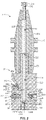
- FIG. 2 illustrates a cross-section of a chip removal device 201 in accordance with an example of the present disclosure, coupled to a typical tool holder 210.
- the chip removal device 201 can include a coupling interface 220, such as a shank or other interfacing structure, to couple with a rotatable spindle of a machine tool.
- the chip removal device 201 can be coupled to a machine tool spindle via the tool holder 210 and can therefore be configured to interface with the tool holder 210.
- the chip removal device 201 can receive pressurized fluid from the machine tool, such as through the spindle.
- the tool holder 210 can be of any suitable configuration to deliver pressurized fluid to a tool.
- the tool holder 210 illustrates an example of a tool holder configured to receive fluid through a center of the tool holder, and to releaseably couple the chip removal device 201.
- the fluid is supplied down the center of the machine tool spindle.
- the tool holder 210 has a retention knob 211 with a central opening 212 and a central opening 213 through a main body portion 214 of the tool holder 210 that allows fluid to pass through the tool holder 210 to a cutting tool.
- This construction can also supply fluid to the chip removal device 201 upon attachment to clean chips from a workpiece.
- fluid is configured to pass through a spindle to a flange 215 of the tool holder.
- some tool holders are configured to receive fluid at a flange inlet port (not shown) and have openings and fluid conduits to fluidly couple the flange inlet to the central opening 213 for delivery of the fluid to a cutting tool.
- the chip removal device 201 can be configured to receive fluid from a typical TSC tool holder, as commonly known in the art, or any other suitable type of tool holder.
- the chip removal device 201 can have a main fluid channel 221 with an opening or inlet port 222 in fluid communication with the central opening 213 of the tool holder 210 to receive pressurized fluid from the machine tool, such as via the tool holder 210.
- the chip removal device 201 can also have one or more fluid delivery channels 230a-b, 231a-b, 232, 233 in fluid communication with the main fluid channel 221. Multiple fluid delivery channels can be included to direct fluid in different directions.
- the fluid delivery channels 230a-b, 231a-b, 232, 233 can be in any suitable orientation relative to an axis of rotation 205 of the spindle.
- outlets of the fluid delivery channels 230a, 231b can be configured to direct fluid in a direction parallel to the axis 205
- outlets of the fluid delivery channels 230b, 231a, 232, 233 can be configured to direct fluid in directions non-parallel or transverse to the axis 205.
- the directions of the fluid delivery channel outlets can be configured to direct coolant in any suitable direction to facilitate cleaning chips from a workpiece.
- the chip removal device 201 can also include one or more valves 240-243 associated with the fluid delivery channels 230a-b, 231a-b, 232, 233 to selectively allow fluid passage from the main fluid channel 221 to the fluid delivery channels.
- one or more of the valves 240-243 can be configured as check valves, which can be actuated by varying fluid pressure and/or spindle rotational speed to control delivery of fluid from the fluid delivery channels 230a-b, 231a-b, 232, 233.
- the valve 240 associated with the fluid delivery channels 230a-b can be configured as a check valve that is normally open.
- the valve 240 can be of any suitable configuration.
- the valve 240 can include an orifice 250, a movable plug 260 to block the orifice 250, and a spring 270 acting on the plug 260.
- the spring 270 can bias the plug 260 away from the orifice 250, such that the valve 240 is normally open.
- the valves 241-243 associated with the fluid delivery channels 231a-b, 232, 233 can be configured as check valves that are normally closed.
- the valves 241-243 can be of any suitable configuration.
- each of the valves 241-243 can include an orifice 251-253, a movable plug 261-263 to block the respective orifices 251-253, and a spring 271-273 acting on the respective plugs 261-263.
- the springs 271-273 can bias the plugs 261-263 toward the respective orifices 251-253, such that the valves 241-243 are normally closed.
- a plug can have any suitable configuration.
- the plugs 260-263 illustrated in FIG. 2 have ball configurations, which may fit into cup-shaped orifice openings formed in the chip removal device 201.
- multiple fluid delivery channels can be associated with a single valve, such that the valve can control fluid flow for all associated channels.
- the fluid delivery channels 230a-b are associated with the valve 240, and the fluid delivery channels 231a-b are associated with the valve 241. Outlets of the fluid delivery channels 230a-b are in different directions from one another, and outlets of the fluid delivery channels 231a-b are in different directions from one another.
- a single valve can control fluid flow in multiple directions at once.
- movement of the plugs 260-263 for a normally open or a normally closed valve can be constrained to be in a direction parallel or non-parallel to the axis of rotation 205 of the spindle.
- movement of the plug 260 can be constrained to be in a direction parallel to the axis of rotation 205 of the spindle. Because the plug 260 does not move radially outward or inward relative to the axis 205, the valve 240 may be actuated only by fluid pressure acting on the plug 260 independent of rotational speed.
- a plug constrained to move in a direction parallel to the axis of rotation 205 can be located off-axis, such as radially outward from the axis 205.
- movement of the plugs can be constrained to be in a direction non-parallel to the axis of rotation 205 of the spindle.
- the valves 241-243 may be actuated by fluid pressure acting on the plugs 261-263 as well as rotation of the spindle about the axis 205, which causes centrifugal force to act on the plugs 261-263, thus causing them to displace.
- the spring rates for the springs 270-273 can be selected, such that particular valves 240-243 open at or above certain fluid pressures and/or rotational speeds, which can be controlled by a program and coordinated with tool position relative to certain features of a workpiece.
- the spring rates of the springs 270-273 can be different from one another to facilitate sequential actuation of the respective valves 240-243 (e.g., with increasing fluid pressures, or with increasing rotational speeds of the spindle) to achieve desired fluid delivery directions for cleaning chips from a workpiece.
- the preload of the springs 270-273 can be selected, such that particular valves 240-243 open at or above certain fluid pressures and/or rotational speeds.
- the preload of the springs 270-273 can be different from one another to facilitate sequential actuation of the respective valves 240-243 to achieve desired fluid delivery directions for cleaning chips from a workpiece.
- the preload of one or more of the springs 270-273 can be adjustable to achieve desired directed fluid delivery performance.
- the springs 271-273 interface with spring seats 281-283 that can be movable relative to the respective orifices 251-253 to adjust preload of the springs.
- the spring seats 281-283 can be movably adjustable in any suitable manner, such as via threaded interfaces (not shown) with a body portion 223 of the chip removal device 201.
- the spring seats 281-283 can include a torque interface (e.g., a slot, hexagonal-shaped interior flat surfaces, star-shaped interior surfaces, etc.) to couple with a tool (e.g., a flat-head screw driver, an Allen key, a star bit or screwdriver, etc.) for rotating the spring seats and adjusting position along the threaded interfaces with the body portion 223.
- a spring seat can be located in a fluid delivery channel, such that the spring seat is in the fluid flow path.
- the spring seat 281 is located in the fluid delivery channel 231a
- the spring seat 282 is located in the fluid delivery channel 232.
- Such spring seats 281, 282 can include respective openings or ports 291, 292 to facilitate passage of fluid through the spring seats.
- valves 240-243 can be adjusted by utilizing springs 270-273 with appropriate spring rates and/or setting appropriate preloads to achieve fluid flow from certain fluid delivery channels by varying fluid pressure and/or rotational speed.
- a fluid delivery channel can be "deactivated” or disabled, for example, by inserting a stopper (not shown) in the channel, such as by utilizing a threaded interface.
- the chip removal device 201 can provide a fluid delivery nozzle that can change the angle (i.e., angle of attack) or direction of fluid delivery to suit the geometry of a given workpiece by varying fluid pressure and/or spindle rotational speed (e.g., rpm). For example, an operator could go from a direct 90° spray with a stationary spindle to a 45° spray to a grazing 0° spray by changing or varying the spindle speed based on the need relative to the geometry of the part. In addition, the ability to direct fluid to different locations with a single tool can save valuable tool space in a tool carriage.
- FIGS. 3A and 3B illustrate cross-sections of a chip removal device 301 in accordance with another example of the present disclosure.
- the chip removal device 301 can include a coupling interface 320, such as a shank, to couple with a rotatable spindle of a machine tool.
- the chip removal device 301 can have a main fluid channel 321 with an opening or inlet port 322 to receive pressurized fluid from the machine tool, such as via a tool holder.
- the chip removal device 301 can also have one or more fluid delivery channels 334a-b in fluid communication with the main fluid channel 321 to direct fluid in different directions.
- the chip removal device 301 includes a single valve 344 that alternates fluid passage from the main channel 321 to the fluid delivery channels 334a-b.
- the valve 344 can have a plug 364 that is movable from a position blocking an orifice 354a of the fluid delivery channel 334a ( FIG. 3A ) to a position blocking an orifice 354b of the fluid delivery channel 334b ( FIG. 3B ).
- the plug 364 can be movable between the alternate channel orifice blocking positions by varying rotational speed of the spindle about an axis 305.
- minimal or no rotational speed can allow gravity to force the plug 364 into the bottom orifice 354a, which directs the fluid from the main fluid channel 321 into the fluid delivery channel 334b.
- Increasing rotational speed can cause centrifugal force to move the plug 364 up a ramp surface 324 into the side orifice 354b, which directs the fluid from the main fluid channel 321 into the fluid delivery channel 334a.
- Decreasing rotational speed allows the plug 364 to move under the influence of gravity to the position blocking the bottom orifice 354a.
- fluid delivery direction can be controlled by adjusting spindle rotational speed.
- a method for removing chips from a workpiece can comprise coupling a machine tool chip removal device to a rotatable spindle of a machine tool for rotation about an axis at a rotational speed.
- the method can also comprise providing pressurized fluid from the machine tool to a main fluid channel of the machine tool chip removal device, the main fluid channel being in fluid communication with first and second fluid delivery channels to direct fluid in different directions, and one or more valves are associated with the first and second fluid delivery channels to selectively allow fluid passage from the main fluid channel to the fluid delivery channels.
- the method can further comprise positioning the machine tool chip removal device relative to a workpiece.
- the method can comprise directing fluid onto the workpiece in one or more directions by varying at least one of fluid pressure and rotational speed to actuate the one or more valves.
- the method can further comprise moving the machine tool chip removal device along a tool path about the workpiece while directing fluid onto the workpiece. It is noted that no specific order is required in this method, though generally in one embodiment, these method steps can be carried out sequentially.
Landscapes
- Engineering & Computer Science (AREA)
- Mechanical Engineering (AREA)
- Auxiliary Devices For Machine Tools (AREA)
Claims (15)
- Vorrichtung zum Entfernen von Werkzeugmaschinenspänen (101, 201, 301), die Folgendes umfasst:eine Spindelkopplungsschnittstelle (220, 320), um sich mit einer drehbaren Spindel einer Werkzeugmaschine (102) zu koppeln, um eine Drehung der Vorrichtung zum Entfernen von Werkzeugmaschinenspänen um eine Achse (205, 305) herum mit einer Drehgeschwindigkeit zu ermöglichen;einen Hauptfluidkanal (221, 321) mit einem Durchlass (222, 322), um unter Druck stehendes Fluid von der Werkzeugmaschine aufzunehmen;einen ersten Fluidabgabekanal (230a-b, 231a-b, 232, 233, 334a) und einen zweiten Fluidabgabekanal (230a-b, 231a-b, 232, 233, 334b), um Fluid in unterschiedliche Richtungen zu leiten, wobei jeder Fluidabgabekanal mit dem Hauptfluidkanal in Fluidverbindung steht; undein oder mehrere Ventile (240-243, 344), die dem ersten und dem zweiten Fluidabgabekanal zugeordnet sind, um einen Fluiddurchgang von dem Hauptfluidkanal zu den Fluidabgabekanälen wahlweise zu ermöglichen, wobei das eine oder die mehreren Ventile konfiguriert sind, um durch ein Variieren von Fluiddruck und/oder Drehgeschwindigkeit betätigt zu werden.
- Vorrichtung zum Entfernen von Werkzeugmaschinenspänen nach Anspruch 1, wobei das eine oder die mehreren Ventile ein Rückschlagventil (240) umfassen, das dem ersten Fluidabgabekanal zugeordnet ist, der offen vorgespannt ist.
- Vorrichtung zum Entfernen von Werkzeugmaschinenspänen nach Anspruch 2, wobei das Rückschlagventil eine Öffnung (250), einen bewegbaren Stopfen (260), um die Öffnung zu blockieren, und eine Feder (270) umfasst, die auf den Stopfen wirkt und den Stopfen von der Öffnung weg vorspannt.
- Vorrichtung zum Entfernen von Werkzeugmaschinenspänen nach Anspruch 3, wobei eine Bewegung des Stopfens in einer Richtung parallel zu der Achse derart erfolgt, dass das Rückschlagventil nur durch Fluiddruck betätigt werden kann, der auf den Stopfen wirkt; oder
wobei ein Auslass des ersten Fluidabgabekanals konfiguriert ist, um Fluid in eine Richtung parallel zu der Achse zu leiten. - Vorrichtung zum Entfernen von Werkzeugmaschinenspänen nach Anspruch 1, wobei das eine oder die mehreren Ventile ein Rückschlagventil (241-243) umfassen, das dem ersten Fluidabgabekanal zugeordnet ist, der geschlossen vorgespannt ist.
- Vorrichtung zum Entfernen von Werkzeugmaschinenspänen nach Anspruch 5, wobei das Rückschlagventil eine Öffnung (251-253), einen bewegbaren Stopfen (261-263), um die Öffnung zu blockieren, und eine Feder (271-273) umfasst, die auf den Stopfen wirkt und den Stopfen in Richtung der Öffnung vorspannt.
- Vorrichtung zum Entfernen von Werkzeugmaschinenspänen nach Anspruch 6, wobei eine Bewegung des Stopfens in einer Richtung, die nicht parallel zu der Achse ist, derart erfolgt, dass das Rückschlagventil wenigstens teilweise durch eine Zentrifugalkraft betätigt wird, die auf den Stopfen wirkt; und
vorzugsweise wobei ein Auslass des ersten Fluidabgabekanals konfiguriert ist, um Fluid in eine Richtung zu leiten, die nicht parallel zu der Achse ist. - Vorrichtung zum Entfernen von Werkzeugmaschinenspänen nach Anspruch 6, wobei eine Vorspannkraft der Feder einstellbar ist; undvorzugsweise wobei die Feder mit einem Federsitz (281-283) verbunden ist, der relativ zu der Öffnung bewegbar ist, um eine Vorspannkraft einzustellen; undvorzugsweise wobei der Federsitz einen Durchlass (291, 292) umfasst, um den Durchgang von Fluid dahindurch zu ermöglichen.
- Vorrichtung zum Entfernen von Werkzeugmaschinenspänen nach Anspruch 1, wobei das eine oder die mehreren Ventile ein erstes Rückschlagventil, das dem ersten Fluidabgabekanal zugeordnet ist, und ein zweites Rückschlagventil umfassen, das dem zweiten Fluidabgabekanal zugeordnet ist, wobei jedes Rückschlagventil eine Öffnung, einen bewegbaren Stopfen, um die Öffnung zu blockieren, und eine Feder aufweist, die auf den Stopfen wirkt und den Stopfen zu der Öffnung hin oder von dieser weg vorspannt; und
vorzugsweise:wobei die Federn unterschiedliche Federkonstanten aufweisen; oderwobei die Federn unterschiedliche Vorspannkräfte aufweisen. - Vorrichtung zum Entfernen von Werkzeugmaschinenspänen nach Anspruch 1, wobei das eine oder die mehreren Ventile ein einzelnes Ventil (344) umfassen, das den Fluiddurchgang von dem Hauptkanal (321) zu dem ersten und dem zweiten Fluidabgabekanal (344a-b) abwechselt; und
vorzugsweise wobei das einzelne Ventil einen Stopfen (364) umfasst, der von einer ersten Position, die den ersten Fluidabgabekanal (334a) blockiert, in eine zweite Position bewegbar ist, die den zweiten Fluidabgabekanal (344b) blockiert. - Vorrichtung zum Entfernen von Werkzeugmaschinenspänen nach Anspruch 1, wobei der Stopfen zwischen der ersten und der zweiten Position durch Variieren der Drehgeschwindigkeit derart bewegbar ist, dass eine abnehmende Drehgeschwindigkeit dem Stopfen ermöglicht, sich in die erste Position unter dem Einfluss von Schwerkraft zu bewegen und eine zunehmende Drehgeschwindigkeit bewirkt, dass eine Zentrifugalkraft den Stopfen in die zweite Position bewegt.
- System zum Entfernen von Werkzeugmaschinenspänen (100), das Folgendes umfasst:eine Werkzeugmaschine (102); undeine Vorrichtung zum Entfernen von Werkzeugmaschinenspänen (101, 201, 301) nach Anspruch 1, die mit der Werkzeugmaschine wirkgekoppelt ist.
- System nach Anspruch 12, wobei die Werkzeugmaschine einen Fräser, eine Drehmaschine oder eine Kombination davon umfasst; oder
wobei das unter Druck stehende Fluid ein Gas und/oder eine Flüssigkeit umfasst. - Verfahren zum Entfernen von Spänen von einem Werkstück, das Folgendes umfasst:Koppeln einer Vorrichtung zum Entfernen von Werkzeugmaschinenspänen (101, 201, 301) an eine drehbare Spindel einer Werkzeugmaschine (102) zum Drehen um eine Achse (205, 305) herum mit einer Drehgeschwindigkeit;Bereitstellen von unter Druck stehendem Fluid von der Werkzeugmaschine an einen Hauptfluidkanal (221, 321) der Vorrichtung zum Entfernen von Werkzeugmaschinenspänen, wobei der Hauptfluidkanal in Fluidverbindung mit ersten und zweiten Fluidabgabekanälen (230a-b, 231a-b, 232, 233, 334a-b) steht, um Fluid in unterschiedliche Richtungen zu leiten, und ein oder mehrere Ventile (240-243, 344) dem ersten und dem zweiten Fluidabgabekanal zugeordnet sind, um wahlweise einen Fluiddurchgang von dem Hauptfluidkanal zu den Fluidabgabekanälen zu ermöglichen;Positionieren der Vorrichtung zum Entfernen von Werkzeugmaschinenspänen relativ zu einem Werkstück (105); undLeiten von Fluid auf das Werkstück in einer oder mehreren Richtungen durch Variieren von Fluiddruck und/oder Drehgeschwindigkeit, um das eine oder die mehreren Ventile zu betätigen.
- Verfahren nach Anspruch 14, das ferner ein Bewegen der Vorrichtung zum Entfernen von Werkzeugmaschinenspänen entlang einer Werkzeugbahn um das Werkstück herum umfasst, während Fluid auf das Werkstück geleitet wird.
Applications Claiming Priority (2)
| Application Number | Priority Date | Filing Date | Title |
|---|---|---|---|
| US15/410,520 US11110562B2 (en) | 2017-01-19 | 2017-01-19 | Machine tool chip removal |
| PCT/US2017/062564 WO2018136145A1 (en) | 2017-01-19 | 2017-11-20 | Machine tool chip removal |
Publications (2)
| Publication Number | Publication Date |
|---|---|
| EP3571007A1 EP3571007A1 (de) | 2019-11-27 |
| EP3571007B1 true EP3571007B1 (de) | 2022-04-06 |
Family
ID=60574757
Family Applications (1)
| Application Number | Title | Priority Date | Filing Date |
|---|---|---|---|
| EP17809140.1A Active EP3571007B1 (de) | 2017-01-19 | 2017-11-20 | Werkzeugmaschinenspanentfernung |
Country Status (3)
| Country | Link |
|---|---|
| US (3) | US11110562B2 (de) |
| EP (1) | EP3571007B1 (de) |
| WO (1) | WO2018136145A1 (de) |
Families Citing this family (9)
| Publication number | Priority date | Publication date | Assignee | Title |
|---|---|---|---|---|
| US11110562B2 (en) | 2017-01-19 | 2021-09-07 | 2865-15.7253.Us.Np | Machine tool chip removal |
| JP6441403B2 (ja) * | 2017-04-13 | 2018-12-19 | ファナック株式会社 | 切削工具保持機構、切削工具ホルダおよび工作機械システム |
| CN111531215B (zh) * | 2020-05-09 | 2021-09-10 | 漳州东刚精密机械有限公司 | 一种龙门数控铣床 |
| CN112354974B (zh) * | 2020-10-27 | 2021-10-29 | 南京迪升动力科技有限公司 | 一种数控机床用的涡旋式冲洗装置 |
| US20220410226A1 (en) * | 2021-06-23 | 2022-12-29 | Paul Thomas Hitchens | Device and process for effectuating slash-cutting of used chemical jugs |
| JP7610814B2 (ja) * | 2021-08-16 | 2025-01-09 | エヌティーツール株式会社 | 冷却媒体噴射装置 |
| JP7659776B2 (ja) * | 2021-08-26 | 2025-04-10 | エヌティーツール株式会社 | 工具ホルダおよびタレット |
| CN113681339A (zh) * | 2021-08-29 | 2021-11-23 | 湖北三环锻造有限公司 | 数控车床自动去除工件缠绕铁屑的方法 |
| US20230087290A1 (en) * | 2021-09-23 | 2023-03-23 | Steve Mark Bryan | Method and device for clearing debris from a machining spindle |
Family Cites Families (12)
| Publication number | Priority date | Publication date | Assignee | Title |
|---|---|---|---|---|
| US2973068A (en) * | 1958-03-07 | 1961-02-28 | Master Power Corp | Impact tool torque control |
| US4287523A (en) * | 1980-02-19 | 1981-09-01 | Ncr Corporation | Valve for ink jet printer |
| SU1140363A1 (ru) | 1982-04-05 | 1986-04-23 | Предприятие П/Я Г-4285 | Эжекторна расточна головка |
| JPH1190762A (ja) | 1997-05-27 | 1999-04-06 | Chiron Werke Gmbh & Co Kg | 工作機械 |
| DE20301772U1 (de) | 2002-09-09 | 2004-03-18 | Nc-Automation Gmbh | Automatisches Reinigungswerkzeug für den Innenraum von NC-Maschinen |
| TW200618979A (en) * | 2004-12-03 | 2006-06-16 | Kou Sheng Feng Entpr Co Ltd | Machine tool having inbuilt water supplier |
| ITMI20052492A1 (it) * | 2005-12-27 | 2007-06-28 | Sunbird Investiments Ltd | Dispositivo di lubrificazione per macchine utensili |
| DE102006053625A1 (de) * | 2006-11-14 | 2008-05-15 | Jäger, Anton | Rotordüse |
| US9204780B2 (en) * | 2011-02-01 | 2015-12-08 | Electrolux Home Products, Inc. | Siphon break apparatus configured to substantially prevent a siphon effect in a fluid conduit of a dishwasher and an associated method |
| DE202013100177U1 (de) | 2013-01-14 | 2014-04-15 | Bilz Werkzeugfabrik Gmbh & Co. Kg | Werkzeughalter sowie Werkzeuganordnung mit einem Werkzeughalter und einem Bearbeitungswerkzeug |
| US9382821B2 (en) * | 2013-11-01 | 2016-07-05 | Fca Us Llc | Biased normally open check valve assembly |
| US11110562B2 (en) * | 2017-01-19 | 2021-09-07 | 2865-15.7253.Us.Np | Machine tool chip removal |
-
2017
- 2017-01-19 US US15/410,520 patent/US11110562B2/en active Active
- 2017-11-20 EP EP17809140.1A patent/EP3571007B1/de active Active
- 2017-11-20 WO PCT/US2017/062564 patent/WO2018136145A1/en not_active Ceased
-
2021
- 2021-01-11 US US17/146,399 patent/US11583969B2/en active Active
-
2023
- 2023-02-21 US US18/112,441 patent/US12059763B2/en active Active
Also Published As
| Publication number | Publication date |
|---|---|
| US20230191550A1 (en) | 2023-06-22 |
| US11583969B2 (en) | 2023-02-21 |
| US20210308816A1 (en) | 2021-10-07 |
| WO2018136145A1 (en) | 2018-07-26 |
| EP3571007A1 (de) | 2019-11-27 |
| US20180200853A1 (en) | 2018-07-19 |
| US11110562B2 (en) | 2021-09-07 |
| US12059763B2 (en) | 2024-08-13 |
Similar Documents
| Publication | Publication Date | Title |
|---|---|---|
| EP3571007B1 (de) | Werkzeugmaschinenspanentfernung | |
| JP6240208B2 (ja) | ワーク着座検出装置及びその調整方法 | |
| EP0988926A2 (de) | Bearbeitungsverfahren | |
| CN112166008B (zh) | 用于切割敏感材料的磨料流体射流切割系统、部件和相关方法 | |
| KR20160009045A (ko) | 물질 제거 기계 공구, 공구 세트, 및 블라인드 및/또는 단차형 보어를 가진 실린더 제조 방법 | |
| CA2637961A1 (en) | Aligning a machine tool with a target location on a structure | |
| CN106660135B (zh) | 主轴装置以及具备该主轴装置的机床 | |
| JP5848911B2 (ja) | 外部及び内部冷却媒体を備えたプルスタッドボルト及び関連する方法 | |
| CN112672849A (zh) | 智能冷却剂泵 | |
| JP7262201B2 (ja) | 冷却液供給装置 | |
| JP2010537836A (ja) | 機械加工装置および方法 | |
| US10744570B2 (en) | Boring bar actuatable by a centrifugal force | |
| EP2509748B1 (de) | Vorrichtung zum schneiden und polieren einer fläche eines werkstücks | |
| JP4009237B2 (ja) | 半導体cmp加工用パッドの細溝加工機械 | |
| US10610992B2 (en) | Automated interchangeable coolant distributor | |
| CN214868619U (zh) | 水车式多工位组合加工机床 | |
| US11358246B2 (en) | Tool bit changing system | |
| JP2010089166A (ja) | 切削加工機 | |
| KR102433322B1 (ko) | Cnc 선반용 절삭유 공급장치 | |
| KR102433318B1 (ko) | Cnc 선반용 절삭유 공급장치 | |
| JP2021526979A (ja) | 90度自動交換機のスピンドル取付アセンブリ | |
| JPH01321141A (ja) | 位置決め固定装置 | |
| CZ19793U1 (cs) | Upínací zarízení pro obrábecí stroje | |
| CN110936102A (zh) | 一种径向双层孔加工方法 | |
| JP6594688B2 (ja) | 着座状態判定条件調整用治具 |
Legal Events
| Date | Code | Title | Description |
|---|---|---|---|
| STAA | Information on the status of an ep patent application or granted ep patent |
Free format text: STATUS: UNKNOWN |
|
| STAA | Information on the status of an ep patent application or granted ep patent |
Free format text: STATUS: THE INTERNATIONAL PUBLICATION HAS BEEN MADE |
|
| PUAI | Public reference made under article 153(3) epc to a published international application that has entered the european phase |
Free format text: ORIGINAL CODE: 0009012 |
|
| STAA | Information on the status of an ep patent application or granted ep patent |
Free format text: STATUS: REQUEST FOR EXAMINATION WAS MADE |
|
| 17P | Request for examination filed |
Effective date: 20190814 |
|
| AK | Designated contracting states |
Kind code of ref document: A1 Designated state(s): AL AT BE BG CH CY CZ DE DK EE ES FI FR GB GR HR HU IE IS IT LI LT LU LV MC MK MT NL NO PL PT RO RS SE SI SK SM TR |
|
| AX | Request for extension of the european patent |
Extension state: BA ME |
|
| DAV | Request for validation of the european patent (deleted) | ||
| DAX | Request for extension of the european patent (deleted) | ||
| GRAP | Despatch of communication of intention to grant a patent |
Free format text: ORIGINAL CODE: EPIDOSNIGR1 |
|
| STAA | Information on the status of an ep patent application or granted ep patent |
Free format text: STATUS: GRANT OF PATENT IS INTENDED |
|
| INTG | Intention to grant announced |
Effective date: 20211105 |
|
| GRAS | Grant fee paid |
Free format text: ORIGINAL CODE: EPIDOSNIGR3 |
|
| GRAA | (expected) grant |
Free format text: ORIGINAL CODE: 0009210 |
|
| STAA | Information on the status of an ep patent application or granted ep patent |
Free format text: STATUS: THE PATENT HAS BEEN GRANTED |
|
| AK | Designated contracting states |
Kind code of ref document: B1 Designated state(s): AL AT BE BG CH CY CZ DE DK EE ES FI FR GB GR HR HU IE IS IT LI LT LU LV MC MK MT NL NO PL PT RO RS SE SI SK SM TR |
|
| REG | Reference to a national code |
Ref country code: GB Ref legal event code: FG4D |
|
| REG | Reference to a national code |
Ref country code: CH Ref legal event code: EP |
|
| REG | Reference to a national code |
Ref country code: AT Ref legal event code: REF Ref document number: 1480861 Country of ref document: AT Kind code of ref document: T Effective date: 20220415 |
|
| REG | Reference to a national code |
Ref country code: IE Ref legal event code: FG4D |
|
| REG | Reference to a national code |
Ref country code: DE Ref legal event code: R096 Ref document number: 602017055648 Country of ref document: DE |
|
| REG | Reference to a national code |
Ref country code: LT Ref legal event code: MG9D |
|
| REG | Reference to a national code |
Ref country code: NL Ref legal event code: MP Effective date: 20220406 |
|
| REG | Reference to a national code |
Ref country code: AT Ref legal event code: MK05 Ref document number: 1480861 Country of ref document: AT Kind code of ref document: T Effective date: 20220406 |
|
| PG25 | Lapsed in a contracting state [announced via postgrant information from national office to epo] |
Ref country code: NL Free format text: LAPSE BECAUSE OF FAILURE TO SUBMIT A TRANSLATION OF THE DESCRIPTION OR TO PAY THE FEE WITHIN THE PRESCRIBED TIME-LIMIT Effective date: 20220406 |
|
| PG25 | Lapsed in a contracting state [announced via postgrant information from national office to epo] |
Ref country code: SE Free format text: LAPSE BECAUSE OF FAILURE TO SUBMIT A TRANSLATION OF THE DESCRIPTION OR TO PAY THE FEE WITHIN THE PRESCRIBED TIME-LIMIT Effective date: 20220406 Ref country code: PT Free format text: LAPSE BECAUSE OF FAILURE TO SUBMIT A TRANSLATION OF THE DESCRIPTION OR TO PAY THE FEE WITHIN THE PRESCRIBED TIME-LIMIT Effective date: 20220808 Ref country code: NO Free format text: LAPSE BECAUSE OF FAILURE TO SUBMIT A TRANSLATION OF THE DESCRIPTION OR TO PAY THE FEE WITHIN THE PRESCRIBED TIME-LIMIT Effective date: 20220706 Ref country code: LT Free format text: LAPSE BECAUSE OF FAILURE TO SUBMIT A TRANSLATION OF THE DESCRIPTION OR TO PAY THE FEE WITHIN THE PRESCRIBED TIME-LIMIT Effective date: 20220406 Ref country code: HR Free format text: LAPSE BECAUSE OF FAILURE TO SUBMIT A TRANSLATION OF THE DESCRIPTION OR TO PAY THE FEE WITHIN THE PRESCRIBED TIME-LIMIT Effective date: 20220406 Ref country code: GR Free format text: LAPSE BECAUSE OF FAILURE TO SUBMIT A TRANSLATION OF THE DESCRIPTION OR TO PAY THE FEE WITHIN THE PRESCRIBED TIME-LIMIT Effective date: 20220707 Ref country code: FI Free format text: LAPSE BECAUSE OF FAILURE TO SUBMIT A TRANSLATION OF THE DESCRIPTION OR TO PAY THE FEE WITHIN THE PRESCRIBED TIME-LIMIT Effective date: 20220406 Ref country code: ES Free format text: LAPSE BECAUSE OF FAILURE TO SUBMIT A TRANSLATION OF THE DESCRIPTION OR TO PAY THE FEE WITHIN THE PRESCRIBED TIME-LIMIT Effective date: 20220406 Ref country code: BG Free format text: LAPSE BECAUSE OF FAILURE TO SUBMIT A TRANSLATION OF THE DESCRIPTION OR TO PAY THE FEE WITHIN THE PRESCRIBED TIME-LIMIT Effective date: 20220706 Ref country code: AT Free format text: LAPSE BECAUSE OF FAILURE TO SUBMIT A TRANSLATION OF THE DESCRIPTION OR TO PAY THE FEE WITHIN THE PRESCRIBED TIME-LIMIT Effective date: 20220406 |
|
| PG25 | Lapsed in a contracting state [announced via postgrant information from national office to epo] |
Ref country code: RS Free format text: LAPSE BECAUSE OF FAILURE TO SUBMIT A TRANSLATION OF THE DESCRIPTION OR TO PAY THE FEE WITHIN THE PRESCRIBED TIME-LIMIT Effective date: 20220406 Ref country code: PL Free format text: LAPSE BECAUSE OF FAILURE TO SUBMIT A TRANSLATION OF THE DESCRIPTION OR TO PAY THE FEE WITHIN THE PRESCRIBED TIME-LIMIT Effective date: 20220406 Ref country code: LV Free format text: LAPSE BECAUSE OF FAILURE TO SUBMIT A TRANSLATION OF THE DESCRIPTION OR TO PAY THE FEE WITHIN THE PRESCRIBED TIME-LIMIT Effective date: 20220406 Ref country code: IS Free format text: LAPSE BECAUSE OF FAILURE TO SUBMIT A TRANSLATION OF THE DESCRIPTION OR TO PAY THE FEE WITHIN THE PRESCRIBED TIME-LIMIT Effective date: 20220806 |
|
| REG | Reference to a national code |
Ref country code: DE Ref legal event code: R097 Ref document number: 602017055648 Country of ref document: DE |
|
| PG25 | Lapsed in a contracting state [announced via postgrant information from national office to epo] |
Ref country code: SM Free format text: LAPSE BECAUSE OF FAILURE TO SUBMIT A TRANSLATION OF THE DESCRIPTION OR TO PAY THE FEE WITHIN THE PRESCRIBED TIME-LIMIT Effective date: 20220406 Ref country code: SK Free format text: LAPSE BECAUSE OF FAILURE TO SUBMIT A TRANSLATION OF THE DESCRIPTION OR TO PAY THE FEE WITHIN THE PRESCRIBED TIME-LIMIT Effective date: 20220406 Ref country code: RO Free format text: LAPSE BECAUSE OF FAILURE TO SUBMIT A TRANSLATION OF THE DESCRIPTION OR TO PAY THE FEE WITHIN THE PRESCRIBED TIME-LIMIT Effective date: 20220406 Ref country code: EE Free format text: LAPSE BECAUSE OF FAILURE TO SUBMIT A TRANSLATION OF THE DESCRIPTION OR TO PAY THE FEE WITHIN THE PRESCRIBED TIME-LIMIT Effective date: 20220406 Ref country code: DK Free format text: LAPSE BECAUSE OF FAILURE TO SUBMIT A TRANSLATION OF THE DESCRIPTION OR TO PAY THE FEE WITHIN THE PRESCRIBED TIME-LIMIT Effective date: 20220406 Ref country code: CZ Free format text: LAPSE BECAUSE OF FAILURE TO SUBMIT A TRANSLATION OF THE DESCRIPTION OR TO PAY THE FEE WITHIN THE PRESCRIBED TIME-LIMIT Effective date: 20220406 |
|
| PLBE | No opposition filed within time limit |
Free format text: ORIGINAL CODE: 0009261 |
|
| STAA | Information on the status of an ep patent application or granted ep patent |
Free format text: STATUS: NO OPPOSITION FILED WITHIN TIME LIMIT |
|
| 26N | No opposition filed |
Effective date: 20230110 |
|
| PG25 | Lapsed in a contracting state [announced via postgrant information from national office to epo] |
Ref country code: AL Free format text: LAPSE BECAUSE OF FAILURE TO SUBMIT A TRANSLATION OF THE DESCRIPTION OR TO PAY THE FEE WITHIN THE PRESCRIBED TIME-LIMIT Effective date: 20220406 |
|
| PG25 | Lapsed in a contracting state [announced via postgrant information from national office to epo] |
Ref country code: SI Free format text: LAPSE BECAUSE OF FAILURE TO SUBMIT A TRANSLATION OF THE DESCRIPTION OR TO PAY THE FEE WITHIN THE PRESCRIBED TIME-LIMIT Effective date: 20220406 |
|
| PG25 | Lapsed in a contracting state [announced via postgrant information from national office to epo] |
Ref country code: MC Free format text: LAPSE BECAUSE OF FAILURE TO SUBMIT A TRANSLATION OF THE DESCRIPTION OR TO PAY THE FEE WITHIN THE PRESCRIBED TIME-LIMIT Effective date: 20220406 |
|
| REG | Reference to a national code |
Ref country code: CH Ref legal event code: PL |
|
| P01 | Opt-out of the competence of the unified patent court (upc) registered |
Effective date: 20230530 |
|
| REG | Reference to a national code |
Ref country code: BE Ref legal event code: MM Effective date: 20221130 |
|
| PG25 | Lapsed in a contracting state [announced via postgrant information from national office to epo] |
Ref country code: LI Free format text: LAPSE BECAUSE OF NON-PAYMENT OF DUE FEES Effective date: 20221130 Ref country code: CH Free format text: LAPSE BECAUSE OF NON-PAYMENT OF DUE FEES Effective date: 20221130 |
|
| PG25 | Lapsed in a contracting state [announced via postgrant information from national office to epo] |
Ref country code: LU Free format text: LAPSE BECAUSE OF NON-PAYMENT OF DUE FEES Effective date: 20221120 |
|
| PG25 | Lapsed in a contracting state [announced via postgrant information from national office to epo] |
Ref country code: IE Free format text: LAPSE BECAUSE OF NON-PAYMENT OF DUE FEES Effective date: 20221120 |
|
| PG25 | Lapsed in a contracting state [announced via postgrant information from national office to epo] |
Ref country code: BE Free format text: LAPSE BECAUSE OF NON-PAYMENT OF DUE FEES Effective date: 20221130 |
|
| PG25 | Lapsed in a contracting state [announced via postgrant information from national office to epo] |
Ref country code: IT Free format text: LAPSE BECAUSE OF FAILURE TO SUBMIT A TRANSLATION OF THE DESCRIPTION OR TO PAY THE FEE WITHIN THE PRESCRIBED TIME-LIMIT Effective date: 20220406 |
|
| PG25 | Lapsed in a contracting state [announced via postgrant information from national office to epo] |
Ref country code: HU Free format text: LAPSE BECAUSE OF FAILURE TO SUBMIT A TRANSLATION OF THE DESCRIPTION OR TO PAY THE FEE WITHIN THE PRESCRIBED TIME-LIMIT; INVALID AB INITIO Effective date: 20171120 |
|
| PG25 | Lapsed in a contracting state [announced via postgrant information from national office to epo] |
Ref country code: CY Free format text: LAPSE BECAUSE OF FAILURE TO SUBMIT A TRANSLATION OF THE DESCRIPTION OR TO PAY THE FEE WITHIN THE PRESCRIBED TIME-LIMIT Effective date: 20220406 |
|
| PG25 | Lapsed in a contracting state [announced via postgrant information from national office to epo] |
Ref country code: MK Free format text: LAPSE BECAUSE OF FAILURE TO SUBMIT A TRANSLATION OF THE DESCRIPTION OR TO PAY THE FEE WITHIN THE PRESCRIBED TIME-LIMIT Effective date: 20220406 |
|
| PG25 | Lapsed in a contracting state [announced via postgrant information from national office to epo] |
Ref country code: MT Free format text: LAPSE BECAUSE OF FAILURE TO SUBMIT A TRANSLATION OF THE DESCRIPTION OR TO PAY THE FEE WITHIN THE PRESCRIBED TIME-LIMIT Effective date: 20220406 |
|
| PG25 | Lapsed in a contracting state [announced via postgrant information from national office to epo] |
Ref country code: BG Free format text: LAPSE BECAUSE OF FAILURE TO SUBMIT A TRANSLATION OF THE DESCRIPTION OR TO PAY THE FEE WITHIN THE PRESCRIBED TIME-LIMIT Effective date: 20220406 |
|
| PG25 | Lapsed in a contracting state [announced via postgrant information from national office to epo] |
Ref country code: BG Free format text: LAPSE BECAUSE OF FAILURE TO SUBMIT A TRANSLATION OF THE DESCRIPTION OR TO PAY THE FEE WITHIN THE PRESCRIBED TIME-LIMIT Effective date: 20220406 |
|
| PG25 | Lapsed in a contracting state [announced via postgrant information from national office to epo] |
Ref country code: TR Free format text: LAPSE BECAUSE OF FAILURE TO SUBMIT A TRANSLATION OF THE DESCRIPTION OR TO PAY THE FEE WITHIN THE PRESCRIBED TIME-LIMIT Effective date: 20220406 |
|
| PGFP | Annual fee paid to national office [announced via postgrant information from national office to epo] |
Ref country code: DE Payment date: 20251022 Year of fee payment: 9 |
|
| PGFP | Annual fee paid to national office [announced via postgrant information from national office to epo] |
Ref country code: GB Payment date: 20251023 Year of fee payment: 9 |
|
| PGFP | Annual fee paid to national office [announced via postgrant information from national office to epo] |
Ref country code: FR Payment date: 20251023 Year of fee payment: 9 |