EP3569916B1 - Haltevorrichtung zum befestigen einer isolierung - Google Patents
Haltevorrichtung zum befestigen einer isolierung Download PDFInfo
- Publication number
- EP3569916B1 EP3569916B1 EP19184309.3A EP19184309A EP3569916B1 EP 3569916 B1 EP3569916 B1 EP 3569916B1 EP 19184309 A EP19184309 A EP 19184309A EP 3569916 B1 EP3569916 B1 EP 3569916B1
- Authority
- EP
- European Patent Office
- Prior art keywords
- holding device
- insulation
- screw
- belt portion
- receptacle
- Prior art date
- Legal status (The legal status is an assumption and is not a legal conclusion. Google has not performed a legal analysis and makes no representation as to the accuracy of the status listed.)
- Active
Links
Images




Classifications
-
- F—MECHANICAL ENGINEERING; LIGHTING; HEATING; WEAPONS; BLASTING
- F16—ENGINEERING ELEMENTS AND UNITS; GENERAL MEASURES FOR PRODUCING AND MAINTAINING EFFECTIVE FUNCTIONING OF MACHINES OR INSTALLATIONS; THERMAL INSULATION IN GENERAL
- F16L—PIPES; JOINTS OR FITTINGS FOR PIPES; SUPPORTS FOR PIPES, CABLES OR PROTECTIVE TUBING; MEANS FOR THERMAL INSULATION IN GENERAL
- F16L59/00—Thermal insulation in general
- F16L59/14—Arrangements for the insulation of pipes or pipe systems
- F16L59/16—Arrangements specially adapted to local requirements at flanges, junctions, valves or the like
- F16L59/18—Arrangements specially adapted to local requirements at flanges, junctions, valves or the like adapted for joints
- F16L59/184—Flanged joints
-
- F—MECHANICAL ENGINEERING; LIGHTING; HEATING; WEAPONS; BLASTING
- F16—ENGINEERING ELEMENTS AND UNITS; GENERAL MEASURES FOR PRODUCING AND MAINTAINING EFFECTIVE FUNCTIONING OF MACHINES OR INSTALLATIONS; THERMAL INSULATION IN GENERAL
- F16L—PIPES; JOINTS OR FITTINGS FOR PIPES; SUPPORTS FOR PIPES, CABLES OR PROTECTIVE TUBING; MEANS FOR THERMAL INSULATION IN GENERAL
- F16L33/00—Arrangements for connecting hoses to rigid members; Rigid hose-connectors, i.e. single members engaging both hoses
- F16L33/02—Hose-clips
- F16L33/08—Hose-clips in which a worm coacts with a part of the hose-encircling member that is toothed like a worm-wheel
-
- F—MECHANICAL ENGINEERING; LIGHTING; HEATING; WEAPONS; BLASTING
- F16—ENGINEERING ELEMENTS AND UNITS; GENERAL MEASURES FOR PRODUCING AND MAINTAINING EFFECTIVE FUNCTIONING OF MACHINES OR INSTALLATIONS; THERMAL INSULATION IN GENERAL
- F16L—PIPES; JOINTS OR FITTINGS FOR PIPES; SUPPORTS FOR PIPES, CABLES OR PROTECTIVE TUBING; MEANS FOR THERMAL INSULATION IN GENERAL
- F16L21/00—Joints with sleeve or socket
- F16L21/06—Joints with sleeve or socket with a divided sleeve or ring clamping around the pipe ends
- F16L21/065—Joints with sleeve or socket with a divided sleeve or ring clamping around the pipe ends tightened by tangentially-arranged threaded pins
-
- F—MECHANICAL ENGINEERING; LIGHTING; HEATING; WEAPONS; BLASTING
- F16—ENGINEERING ELEMENTS AND UNITS; GENERAL MEASURES FOR PRODUCING AND MAINTAINING EFFECTIVE FUNCTIONING OF MACHINES OR INSTALLATIONS; THERMAL INSULATION IN GENERAL
- F16L—PIPES; JOINTS OR FITTINGS FOR PIPES; SUPPORTS FOR PIPES, CABLES OR PROTECTIVE TUBING; MEANS FOR THERMAL INSULATION IN GENERAL
- F16L59/00—Thermal insulation in general
- F16L59/14—Arrangements for the insulation of pipes or pipe systems
- F16L59/16—Arrangements specially adapted to local requirements at flanges, junctions, valves or the like
- F16L59/168—Flexible insulating material or covers for flanges, junctions, valves or the like
-
- F—MECHANICAL ENGINEERING; LIGHTING; HEATING; WEAPONS; BLASTING
- F16—ENGINEERING ELEMENTS AND UNITS; GENERAL MEASURES FOR PRODUCING AND MAINTAINING EFFECTIVE FUNCTIONING OF MACHINES OR INSTALLATIONS; THERMAL INSULATION IN GENERAL
- F16L—PIPES; JOINTS OR FITTINGS FOR PIPES; SUPPORTS FOR PIPES, CABLES OR PROTECTIVE TUBING; MEANS FOR THERMAL INSULATION IN GENERAL
- F16L23/00—Flanged joints
- F16L23/04—Flanged joints the flanges being connected by members tensioned in the radial plane
Definitions
- the invention relates to a holding device for fastening insulation to a V-band clamp or to another connecting device for pipe ends to be connected, according to the preamble of patent claim 1.
- V-band clamps It is already known from the prior art to connect two pipe ends of a pipeline using so-called V-band clamps.
- a V-band clamp has a V-shaped or substantially V-shaped elongated receptacle.
- the socket is bent so that it embraces and grips axially opposite annular projections of the tube ends.
- the circumference of the V-band clamp is reduced until it or the elongated seat is firmly attached to the pipe ends.
- the pipe ends are connected to one another mechanically, preferably in a fluid-tight manner. Hot gases or liquids in particular can then be passed through a pipeline created in this way.
- the V-band clamp when hot media are routed through the pipeline, the V-band clamp is heated and can therefore radiate heat to surrounding components in an undesirable manner.
- the V-band clamp is placed near temperature-sensitive components, for example close to plastic components, electronic controllers or sensors, these components can be adversely affected by the heat.
- V-band clamps often have to be fitted with suitable insulation.
- insulation usually consists of insulating mats or made-up, flexible molded insulating parts.
- the insulations include temperature-resistant technical fabrics and insulating materials or temperature-resistant fabric tapes used for bandaging and wrapping.
- the DE 43 25 757 A1 shows a holding device with a screw connection.
- the EP 0 486 299 A1 shows a holding device in which metal fingers are bent over for attachment after they have been pulled through slits as a pulling element.
- the holding devices known from fire protection are designed for static applications and are not suitable for fixing insulation on V-band clamps in a manner suitable for operation.
- the invention is therefore based on the object of providing a V-band clamp or another connecting device for pipe ends to be connected with insulation which, after simple assembly, has the longest possible service life.
- a holding device for fastening insulation to a V-band clamp or to another connecting device for pipe ends to be connected comprises closure elements, the outer and/or inner circumference of the holding device being able to be reduced through the interaction of the closure elements, and a flexible belt section, the Belt section can be placed around insulation as part of an outer jacket or in the manner of an outer jacket.
- a flexible holding device is specified which protects the actual insulating material from the environmental influences mentioned and can be assembled without great technical effort.
- the insulation surrounds the V-band clamp at its outer perimeter and is held in place by the retainer.
- the belt section protects the insulation from external influences and at least partially or completely encloses the insulation.
- the holding device thus protects in the manner of an outer casing at least in some areas against external influences, for example against stone chipping, splashing water and the like.
- the holding device enables a permanent, vibration-compatible attachment of an isolation system to the V-band clamp.
- the belt portion is connected directly or indirectly to a hood for receiving a protrusion or closure of a V-band clamp or other pipe end connection device.
- the hood ensures that a closure, namely usually a screw connection of the V-band clamp, can be accommodated inside the hood when the holding device is placed around the V-band clamp together with the insulation.
- the insulation can advantageously move into the hood if it is displaced by an overhang or closure.
- the hood largely or completely prevents the holding device from being deformed in an undesired manner and deviating from a round shape in critical areas.
- the hood also offers protection against external influences.
- the belt section and the hood could form an outer jacket that is closed at least in certain areas for encircling the insulation and/or the V-band clamp in the radial and/or axial direction. This protects the insulation and the V-band clamp particularly well against external influences.
- the holding device is permanently fastened with a screw connection. Tightening a screw reduces the outer and inner circumference of the retainer so that it radially presses the insulation against the V-band clamp.
- the insulation must be positioned between the V-band clamp and the holding device in a manner appropriate for operation.
- the person doing the assembly must make a screw connection and tighten a screw.
- the holding device is preferably made of a metal, preferably stainless steel. Metals can easily be reversibly or irreversibly bent. Due to its resistance to corrosion, stainless steel is particularly preferably used to manufacture a holding device described here. The entire holding device is therefore preferably made of stainless steel.
- the holding device is preferably designed in one piece.
- the tensile body and/or the material from which the belt portion and/or the entire holding device is made could have a thickness in the range 0.25 to 1 mm. Such a thickness has proven to be advantageous, on the one hand, to be able to easily bend over the traction body and the belt section and, on the other hand, to be able to carry out stamping or laser processes relatively easily in order to be able to form structures in the belt section.
- the belt section could have or form a receptacle for inserting or applying insulation, with the belt section having an inner contact base from which support segments protrude on both sides, which are spaced apart from one another by recesses.
- the receptacle is preferably designed to be essentially U-shaped in cross section.
- the support segments protrude from the contact base in such a way that it is difficult or impossible for the insulation to deviate in the axial direction.
- the contact base is preferably designed as a closed plane, which prevents the insulation from deflecting in the radial direction.
- At least two support segments could taper in width in the direction of projection, with a recess lying between them in Abrageraum expanded such that the support segments can approach each other when bending the belt portion to reduce the outer and / or inner circumference with their side edges and the recess is thereby reduced in width.
- the support segments preferably do not initially hit one another.
- the recesses promote the bending behavior of the belt section through targeted material weakening.
- the recesses are formed so that the support segments come as close as possible to each other as the belt portion flexes, promoting shielding of the insulation and V-band clamp in the axial direction.
- the support segments do not taper in one direction, but that the recesses are suitably selected so that the support segments can approach each other when the belt section bends or even overlap in some areas.
- the insulation could be connected to the holding device at least at one point.
- the insulation is preferably fixed to the second closure element.
- the insulation is captively connected to the holding device.
- the installer can place the insulation in the socket and wrap the retainer around a V-band clamp.
- the insulation could be designed as an insulating molded part, with the insulation having a glass fiber fabric or a fine wire fabric.
- the two closure elements are connected to one another by a screw connection, with a screw having a threaded screw end being received in a screw counter-receptacle and the screw being able to be screwed into the screw counter-receptacle to reduce the outer and/or inner circumference of the holding device.
- a screw connection can be easily detached again.
- the screw is received with its threaded screw end in a rotatable screw counter-receptacle or is pivotably received and is suspended in a suspension bearing with a free end, which has a screw head. This simplifies assembly and attaches the screw captively to the holding device.
- the rotary screw counter mount is associated with the belt portion and the hanger bearing is associated with the hood.
- An elongate screw can thus protrude in the direction of the belt section. The screw protruding beyond the hood or the screw protruding in a disruptive manner can be avoided.
- the insulation could have a lamination which faces away from the abutment base and/or is arranged radially inwards.
- the lamination can protect underlying insulating material from abrasion.
- Areas of the insulation could be connected to the holding device by an adhesive.
- An adhesive can be used inexpensively and for rapid manufacture.
- a tool could be provided as an isolated replacement part for setting a fixture of the type described herein.
- the tool could include a gripping end with a slot open on one side, into which the traction body can be inserted, and an adapter end.
- the adapter end could be square, hexagonal or otherwise.
- the tool could be in the form of a pin to allow the traction body to be wrapped around the tool.
- the adapter end of the pin is designed in such a way that it can be easily gripped by a chuck of a cordless screwdriver, drill or wrench for turning or rotating.
- the holding device described here is particularly suitable for use in dynamically loaded pipe connections.
- the holding device is preferably flexibly bendable and made of metal.
- the 1 and 9 each show a holding device 1, 1' for fastening insulation to a V-band clamp or to another connecting device for pipe ends to be connected, comprising closure elements 2, 2', 3, 3', whereby the interaction of the closure elements 2, 2' , 3, 3 'the outer and / or inner circumference of Holding device 1, 1 'can be reduced.
- Both holding devices 1, 1' comprise a bendable belt section 4 which can be placed around insulation as part of an outer jacket or in the manner of an outer jacket.
- the belt section 4 is and/or can be connected directly or indirectly to a hood 23, 23' for receiving an overhang or closure of a V-band clamp or other connection device for pipe ends.
- the Figures 1 to 6 show a holding device 1 in which the two closure elements 2, 3 can be connected or are connected to one another, the first closure element 2 having a tension body 5 or being designed as such, the second closure element 3 having a recess 6 through which the tension body 5 can be Reduction of the outer and / or inner circumference of the holding device 1 can be pulled through or pulled through, and the pulling body 5 can be wound up or is wound up and rests against an abutment 8 during winding up or in the wound up state.
- the second closure element 3 is designed as a hood 23 , the recess 6 being designed in the hood 23 .
- FIGS. 1 to 4 concretely show a holding device 1 for fastening insulation (not shown), comprising a first end, to which a first closure element 2 is assigned, a second end, to which a second closure element 3 is assigned, and a flexible belt section 4, which extends between the closure elements 2, 3, the two ends being connectable or connected to one another by interaction of the closure elements 2, 3, the first closure element 2 having a tension body 5 and the second closure element 3 having a recess 6 through which the tension body 5 can be pulled or pulled through .
- the Figures 1 to 3 show that the traction body 5 can be wound up and its outer surface 7 bears against an abutment 8 of the second closure element 3 when it is wound up.
- the traction body 5 can be wound up and rests against the abutment 8 when it is being wound up and is supported on this.
- the train body 5 can be wound up spirally by hand or with a cordless screwdriver and inserted into the in 4 state shown.
- the traction body 5 is designed as an elongated strip or elongated tongue or in the manner of a strip or tongue. At its free end, it has a constriction 9 that allows it to be easily gripped and bent or wound up by a tool.
- the tensile body 5 and the material from which the belt portion 4 and the entire holding device 1 are made have a thickness of 0.5 mm.
- the Figures 1 to 5 show that the belt section 4 has a receptacle 10 for inserting or applying insulation and that receptacle 10 is formed.
- the belt section 4 has an inner contact base 11 from which support segments 12 protrude on both sides, which are spaced apart from one another by recesses 13 .
- At least two support segments 12 taper in width in the direction of protrusion, with a recess 13 located between them expanding in the direction of protrusion in such a way that the support segments 12 can approach each other with their side edges when the belt section 4 is bent to reduce the outer and/or inner circumference and the width of the recess 13 is thereby reduced.
- the support segments 12 are spaced apart from one another by the recesses 13 .
- the support segments 12 protrude from the contact base 11, each of which encloses an angle of 80 to 100° with it. this is in figure 5 shown particularly clearly.
- a plurality of adjacent support segments 12 are each arranged in the manner of a palisade on opposite longitudinal sides of the system base 11 .
- a recess 13 in the form of a slot which is open on one side and widens in a V-shape is formed between two adjacent support segments 12 in each case.
- the recesses 13 can be introduced by stamping processes or a laser.
- the holding device 1 is formed in one piece from a metallic layer.
- the metallic layer consists of stainless steel.
- the metallic layer has a thickness of 0.5 mm.
- the protruding side elements shown on the left can be bent due to a continuous edging and connected to the second closure element 3 or to the hood 23 by riveted connections.
- the support segments 12 can also be bent over to form a receptacle 10 due to the edging.
- the first closure element 2 and the traction body 5 are designed in one piece and merge into one another.
- the traction body 5 opens into the first closure element 2 in that the width of the traction body 5 increases. As a result, the traction body 5 can only be pulled through the recess 6 over a certain length.
- the tool 14 comprises a gripping end 15 with a slot 16 open on one side, into which the traction body 5 can be inserted, and an adapter end 17, which is designed as a hexagon 18.
- the gripping end 15 is used to grip and wind up the traction body 5.
- the adapter end 17 can be connected to a rotating or rotatable chuck.
- the adapter end 17 is provided with a hexagon 18 for this purpose.
- the adapter end 17 is designed differently in order to be able to be easily taken by a tool.
- the tool 14 described above can be used to carry out a method for fastening insulation 19 using the holding device 1, with the first end of the holding device 1 to which the first closure element 2 being assigned and the second end of the holding device 1 to which the second closure element 3 being assigned are connected to each other, whereby the belt portion 4, which extends between the fastener elements 2, 3, is bent, the two ends being connected by an interaction of the fastener elements 2, 3, by pulling the tensile body 5 of the first fastener element 2 through the recess 6 of the second closure element 3 is pulled, with the tension body 5 being wound up to reduce the outer and inner circumference of the holding device 1 and to fix it, and with its outer surface 7 being in contact with an abutment 8 of the second closure element 3 when being wound up or in the wound up state.
- the winding takes place by turning the tool 14, the slot 16 of which engages with the pulling body 5.
- FIG. 8 shows on the right side in a schematic view an arrangement comprising two pipe ends 20, 21, which are gas-tight and firmly connected to one another by a V-band clamp 22, the V-band clamp 22 being surrounded by insulation 19 and where the insulation 19 is accommodated in the receptacle 10 of the holding device 1.
- the holding device 1 presses the insulation 19 radially against the V-band clamp 22 and encloses both the V-band clamp 22 and the insulation 19 in the radial and axial direction in the manner of an outer jacket.
- the insulation 19 and the V-band clamp 22 are hereby protected from stone chipping when the arrangement is arranged, for example, on an underbody of a motor vehicle.
- the pipe ends 20, 21 are each additionally insulated by an insulating jacket 24, which ends inside the holding device 1 in order to produce almost complete insulation.
- the insulation 19 is connected to the holding device 1 at least at one point.
- the insulation 19 is fixed to the second closure element 3 .
- only one traction body 5 is provided.
- the recess 6 in the second closure element 3 is designed as a slot surrounded on four sides. In this way, the traction body 5 cannot deviate to the side.
- the slot or the recess 6 is elongate.
- the slot or the recess 6 is so narrow that the traction body 5 can be guided through with little play. As a result, the traction body 5 can no longer slide back through the slot or the recess 6, even if it is wound up only slightly, that is to say with only a few windings.
- FIG. 9 shows a holding device 1', in which a screw 25 is used instead of a traction body in order to connect the closure elements 2', 3' to one another.
- the second closure element 3' is designed as a hood 23'.
- Figures 10 to 14 show the holding device 1" according to the invention, in which the two closure elements 2', 3' are connected to one another by a screw connection.
- a screw 25 is received with a threaded screw end in a screw counter-receptacle 26, and the screw 25 can be screwed into the screw counter-receptacle 26 to reduce the outer and/or inner circumference of the holding device 1".
- the screw 25 is accommodated with its threaded screw end in a rotatable screw counter-receptacle 26 and can be pivoted.
- the screw 25 can be suspended in a suspension bearing 27 with a free end which has a screw head. After hanging in, the holding device 1" can be pressed against radially inner elements by screwing the screw 25 into the screw counter-receptacle 26.
- the rotatable screw counter-receptacle 26 is associated with the belt portion 4, namely fixed to it.
- the suspension bearing 27 is assigned to the hood 23', namely fixed to it.
- the insulation 19 has a lamination 28 which faces away from the abutment base 11 and is arranged radially inwards.
- the lamination 28 is applied to an insulating material 30 .
- the insulation 19 is connected to the holding device 1'' in some areas by means of an adhesive 29.
- the holding device 1′′ has a recess 6 in its hood 23′, through which a traction body 5 could be pulled.
- a combination of a screw connection and a connection by means of the traction body 5 described here is conceivable.
Landscapes
- Engineering & Computer Science (AREA)
- General Engineering & Computer Science (AREA)
- Mechanical Engineering (AREA)
- Clamps And Clips (AREA)
- Thermal Insulation (AREA)
Description
- Die Erfindung betrifft eine Haltevorrichtung zum Befestigen einer Isolierung an einer V-Band-Schelle oder an einer anderen Verbindungsvorrichtung für zu verbindende Rohrenden gemäß dem Oberbegriff des Patentanspruchs 1.
- Aus der
EP 2 148 124 A1 ist eine solche Haltevorrichtung mit einem sehr kurzen Zugkörper, nämlich lediglich einer Lasche, bekannt, die umgebogen werden kann, um zwei Enden eines Gürtelabschnitts zu verbinden. DieJP S60-38992 U US 2007/0209166 A1 zeigen vor diesem Hintergrund Schraubverbindungen, bei denen eine Mutter auf eine nicht drehbare Schraube aufgedreht werden muss, um einen Umfang der Haltevorrichtung zu verringern. DieEP 2 241 766 A1 zeigt eine Schraubverbindung, bei der eine Schraube in eine Mutter in einem Gehäuse eindrehbar ist. - Aus dem Stand der Technik ist es bereits bekannt, zwei Rohrenden einer Rohrleitung durch sogenannte V-Band-Schellen zu verbinden. Eine V-Band-Schelle weist eine V-förmige oder im Wesentlichen V-förmige längliche Aufnahme auf. Die Aufnahme wird derart gebogen, dass sie axial einander gegenüberliegende ringförmige Vorsprünge der Rohrenden umfängt und umgreift. Durch Anziehen einer Schraube wird der Umfang der V-Band-Schelle solange verringert, bis diese bzw. die längliche Aufnahme fest an den Rohrenden anliegt. Hierdurch werden die Rohrenden mechanisch, vorzugsweise fluiddicht, miteinander verbunden. Durch eine so geschaffene Rohrleitung können dann insbesondere heiße Gase oder Flüssigkeiten geführt werden.
- Bei der Führung von heißen Medien durch die Rohrleitung wird die V-Band-Schelle allerdings erwärmt und kann daher in unerwünschter Weise Wärme auf umliegende Bauteile abstrahlen. Insbesondere wenn die V-Band-Schelle in der Nähe von temperaturempfindlichen Bauteilen, beispielsweise nahe bei Kunststoffbauteilen, elektronischen Reglern oder Sensoren, angeordnet ist, können diese Bauteile durch die Wärme negativ beeinträchtigt werden.
- Außerdem kann es wünschenswert sein, den Verlust von Wärme zu minimieren, um den Energieerhalt in einem fluidführenden System zu optimieren. Um diesen Problemen zu begegnen, müssen V-Band-Schellen häufig mit geeigneten Isolierungen versehen werden. Solche Isolierungen bestehen in der Regel aus Isoliermatten oder aus konfektionierten flexiblen Isolierformteilen. Die Isolierungen weisen temperaturbeständige technische Gewebe und Isoliermaterialien auf oder temperaturbeständige Gewebebänder, die zur Bandagierung und Umwicklung verwendet werden.
- Manche Isolierungen werden um einen zu isolierenden Körper gelegt und mit Druckknöpfen befestigt. Andere Isolierungen werden mit Haken und Spannfedern befestigt, die in die Isolierungen eingehängt sind. Diese Isolierungen sind jedoch weder steinschlagfest noch spritzwasserbeständig. Des Weiteren zeigen sie bei Ihrer Verwendung unter dynamischer Belastung nur eine geringe Vibrationsbeständigkeit und sind daher nur von geringer Dauerhaltbarkeit.
- Vor diesem Hintergrund sind aus dem Brandschutz bereits Haltevorrichtungen für intumeszierende Materialien bekannt. Die
DE 43 25 757 A1 zeigt eine Haltevorrichtung mit einer Schraubverbindung. DieEP 0 486 299 A1 zeigt eine Haltevorrichtung, bei welcher zur Befestigung metallische Finger umgebogen werden, nachdem diese durch Schlitze als Zugkörper durchgezogen wurden. Die aus dem Brandschutz bekannten Haltevorrichtungen sind für statische Anwendungen ausgelegt und nicht geeignet, Isolierungen an V-Band-Schellen betriebstauglich festzulegen. - Der Erfindung liegt daher die Aufgabe zugrunde, eine V-Band-Schelle oder eine andere Verbindungsvorrichtung für zu verbindende Rohrenden mit einer Isolierung zu versehen, welche nach einfacher Montage eine möglichst lange Betriebslebenszeit zeigt.
- Die vorliegende Erfindung löst die Aufgabe durch die Merkmale des Patentanspruchs 1.
- Erfindungsgemäß umfasst eine Haltevorrichtung zum Befestigen einer Isolierung an einer V-Band-Schelle oder an einer anderen Verbindungsvorrichtung für zu verbindende Rohrenden Verschlusselemente, wobei durch Zusammenwirken der Verschlusselemente der Außen- und/ oder Innenumfang der Haltevorrichtung verringerbar ist, und einen biegbaren Gürtelabschnitt, wobei der Gürtelabschnitt als Teil eines Außenmantels oder nach Art eines Außenmantels um eine Isolierung legbar ist. Zur Verbesserung der Dauerhaltbarkeit, der Steinschlagfestigkeit, Spritzwasserdichtigkeit, Vibrationsbeständigkeit und der Montage von Isolierungen für V-Band-Schellen wird hierdurch eine flexible Haltevorrichtung angegeben, welche den eigentlichen Isolierwerkstoff vor den genannten Umwelteinflüssen schützt und ohne großen technischen Aufwand montierbar ist. Die Isolierung umgibt die V-Band-Schelle an deren äußerem Umfang und wird durch die Haltevorrichtung gehalten. Der Gürtelabschnitt schützt die Isolierung vor äußeren Einflüssen und umfängt die Isolierung zumindest bereichsweise oder vollständig. Die Haltevorrichtung schützt so nach Art eines Außenmantels zumindest bereichsweise gegen äußere Einwirkungen, zum Beispiel gegen Steinschlag, Spritzwasser und ähnliches. Die Haltevorrichtung ermöglicht eine dauerhafte vibrationsgerechte Befestigung eines Isoliersystems auf der V-Band-Schelle.
- Der Gürtelabschnitt ist mittelbar oder unmittelbar mit einer Haube zur Aufnahme eines Überstands oder Verschlusses einer V-Band-Schelle oder einer anderen Verbindungsvorrichtung für Rohrenden verbunden.
- Die Haube stellt sicher, dass ein Verschluss, nämlich in der Regel eine Schraubverbindung der V-Band-Schelle, innerhalb der Haube aufnehmbar ist, wenn die Haltevorrichtung um die V-Band-Schelle nebst Isolierung gelegt wird.
- Die Isolierung kann vorteilhaft in die Haube ausweichen, wenn diese durch einen Überstand oder Verschluss verdrängt wird. Durch die Haube wird weitgehend oder vollständig vermieden, dass die Haltevorrichtung in unerwünschter Weise deformiert wird und an kritischen Bereichen von einer runden Form abweicht.
- Die Haube bietet des Weiteren ebenfalls Schutz vor äußeren Einflüssen. Vor diesem Hintergrund könnten der Gürtelabschnitt und die Haube einen zumindest bereichsweise geschlossenen Außenmantel zum Umfangen der Isolierung und/ oder der V-Band-Schelle in radialer und/ oder axialer Richtung bilden. Hierdurch werden die Isolierung und die V-Band-Schelle besonders gut gegen äußere Einflüsse geschützt.
- Die Haltevorrichtung ist, wie eine V-Band-Schelle, durch eine Schraubverbindung dauerhaft befestigt. Durch das Anziehen einer Schraube wird der Außen- und Innenumfang der Haltevorrichtung verringert, so dass diese die Isolierung an die V-Band-Schelle in radialer Richtung andrückt. Bei dieser Montage ist allerdings zu beachten, dass die Isolierung betriebsgerecht zwischen V-Band-Schelle und Haltevorrichtung positioniert werden muss. Zugleich muss von der montierenden Person eine Schraubverbindung hergestellt und eine Schraube angezogen werden.
- Bevorzugt ist die Haltevorrichtung, aber insbesondere der Zugkörper, aus einem Metall, bevorzugt aus Edelstahl, gefertigt. Metalle lassen sich leicht reversibel oder irreversibel umbiegen. Edelstahl wird aufgrund seiner Korrosionsbeständigkeit besonders bevorzugt verwendet, um eine hier beschriebene Haltevorrichtung zu fertigen. Bevorzugt ist daher die gesamte Haltevorrichtung aus Edelstahl gefertigt. Die Haltevorrichtung ist bevorzugt einteilig ausgestaltet.
- Der Zugkörper und/ oder das Material, aus dem der Gürtelabschnitt und/ oder die gesamte Haltevorrichtung gefertigt ist, könnte bzw. könnten eine Dicke im Bereich 0,25 bis 1 mm aufweisen. Eine solche Dicke hat sich als vorteilhaft erwiesen, um einerseits den Zugkörper und den Gürtelabschnitt leicht umbiegen zu können und andererseits relativ leicht Stanz- oder Laserprozesse durchführen zu können, um im Gürtelabschnitt Strukturen ausbilden zu können.
- Vor diesem Hintergrund könnte der Gürtelabschnitt eine Aufnahme zum Ein- oder Anlegen einer Isolierung aufweisen oder ausbilden, wobei der Gürtelabschnitt eine innere Anlagebasis aufweist, von welcher beidseitig Stützsegmente abragen, welche durch Aussparungen voneinander beabstandet sind. Die Aufnahme ist bevorzugt im Querschnitt im Wesentlichen U-förmig ausgebildet. Die Stützsegmente ragen derart von der Anlagebasis ab, dass ein Ausweichen der Isolierung in axialer Richtung erschwert oder verhindert ist. Die Anlagebasis ist bevorzugt als geschlossene Ebene ausgebildet, welche ein Ausweichen der Isolierung in radialer Richtung verhindert.
- Mindestens zwei Stützsegmente könnten sich in Abragerichtung in ihrer Breite verjüngen, wobei sich eine zwischen diesen liegende Aussparung in Abragerichtung derart erweitert, dass sich die Stützsegmente beim Biegen des Gürtelabschnitts zur Verringerung des Außen- und/ oder Innenumfangs mit ihren Seitenkanten einander annähern können und sich die Aussparung dabei in ihrer Weite verringert. Hierdurch wird das Biegen des Gürtelabschnitts erleichtert. Die Stützsegmente stoßen beim Biegen vorzugsweise zunächst nicht aneinander an. Die Aussparungen begünstigen durch gezielte Materialschwächung das Biegeverhalten des Gürtelabschnitts. Die Aussparungen sind so ausgebildet, dass sich die Stützsegmente beim Biegen des Gürtelabschnitts möglichst nahe kommen und eine Abschirmung der Isolierung und der V-Band-Schelle in axialer Richtung begünstigen.
- Vor diesem Hintergrund ist auch denkbar, dass sich die Stützsegmente nicht in einer Richtung verjüngen, aber die Aussparungen geeignet gewählt sind, damit sich die Stützsegmente beim Biegen des Gürtelabschnitts annähern oder sogar bereichsweise einander überlappen können.
- Die Isolierung könnte zumindest an einer Stelle mit der Haltevorrichtung verbunden sein. Bevorzugt ist die Isolierung am zweiten Verschlusselement festgelegt. Hierdurch ist die Isolierung verliersicher mit der Haltevorrichtung verbunden. Die montierende Person kann die Isolierung in die Aufnahme einlegen und die Haltevorrichtung um eine V-Band-Schelle herumlegen. Die Isolierung könnte als Isolierformteil ausgebildet sein, wobei die Isolierung ein Glasfasergewebe oder ein Feindrahtgewebe aufweist.
- Die beiden Verschlusselemente sind durch eine Schraubverbindung miteinander verbunden, wobei eine Schraube mit einem gewindetragenden Schraubenende in einer Schrauben-Gegenaufnahme aufgenommen ist und die Schraube zur Verringerung des Außen- und/ oder Innenumfangs der Haltevorrichtung in die Schrauben-Gegenaufnahme eindrehbar ist. Eine Schraubverbindung ist leicht wieder lösbar.
- Die Schraube ist mit ihrem gewindetragenden Schraubenende in einer drehbaren Schrauben-Gegenaufnahme aufgenommen oder verschwenkbar aufgenommen und mit einem freien Ende, welches einen Schraubenkopf aufweist, in ein Einhängelager eingehängt. Hierdurch ist die Montage vereinfacht und die Schraube verliersicher an der Haltevorrichtung angebracht.
- Die drehbare Schrauben-Gegenaufnahme ist dem Gürtelabschnitt zugeordnet, und das Einhängelager ist der Haube zugeordnet. So kann eine längliche Schraube in Richtung des Gürtelabschnitts abragen. Ein Überragen der Haube durch die Schraube bzw. ein störendes Abstehen der Schraube kann vermieden werden.
- Die Isolierung könnte eine Laminierung aufweisen, welche der Anlagebasis abgewandt und/ oder nach radial innen angeordnet ist. Die Laminierung kann hinter ihr liegendes Isoliermaterial vor Abrieb schützen.
- Die Isolierung könnte bereichsweise durch einen Klebstoff mit der Haltevorrichtung verbunden sein. Ein Klebstoff kann kostengünstig und zur raschen Fertigung eingesetzt werden.
- Ein Werkzeug könnte als isoliertes Ersatzteil zum Festlegen einer Haltevorrichtung der hier beschriebenen Art bereitgestellt werden. Das Werkzeug könnte ein Greifende mit einem einseitig offenen Schlitz umfassen, in welchen der Zugkörper einschiebbar ist, und ein Adapterende. Das Adapterende könnte als Vierkant, Sechskant oder in anderer Weise ausgebildet sein. Das Werkzeug könnte stiftförmig ausgebildet sein, damit der Zugkörper um das Werkzeug herumgewickelt werden kann. Das Adapterende des Stifts ist derart ausgebildet, dass es leicht von einem Futter eines Akkuschraubers, einer Bohrmaschine oder eines Schlüssels zum Drehen oder Rotieren ergriffen werden kann.
- Die hier beschriebene Haltevorrichtung ist insbesondere zur Verwendung bei dynamisch belasteten Rohrverbindungen geeignet. Die Haltevorrichtung ist bevorzugt flexibel biegbar und aus Metall gefertigt.
- In der Zeichnung zeigen
- Fig. 1
- eine perspektivische Ansicht einer nicht erfindungsgemäßen Haltevorrichtung zum Befestigen einer Isolierung, wobei die Haltevorrichtung noch nicht endgültig geschlossen ist, jedoch der Zugkörper zur provisorischen Verbindung der Verschlusselemente bereits durch die Ausnehmung eines zweiten Verschlusselements gezogen ist, welches als Haube ausgestaltet ist,
- Fig. 2
- eine weitere perspektivische Ansicht der Haltevorrichtung gemäß
Fig. 1 , wobei eine Ansicht auf die Innenfläche des Zugkörpers dargestellt ist, - Fig. 3
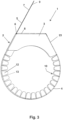
- eine Seitenansicht der Haltevorrichtung gemäß
Fig. 1 und2 , - Fig. 4
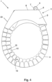
- eine Ansicht der Haltevorrichtung gemäß
Fig. 1 , wobei die Haltevorrichtung betriebstauglich geschlossen und der Zugkörper spiralförmig aufgewickelt ist, - Fig. 5
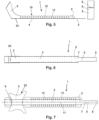
- auf der linken Seite eine Seitenansicht der Haltevorrichtung gemäß
Fig. 1 in aufgerolltem Zustand und in einer Ebene liegend und auf der rechten Seite die schlitzförmige Ausnehmung des zweiten Verschlusselements in einer Draufsicht, - Fig. 6
- eine Ansicht der Haltevorrichtung gemäß
Fig. 5 von unten, - Fig. 7
- eine Ansicht eines Rohlings, aus welchem die Haltevorrichtung gemäß
Fig. 1 gefertigt wird, - Fig. 8
- auf der linken Seite ein Werkzeug zum Aufwickeln des Zugkörpers und auf der rechten Seite eine schematische Darstellung einer Anordnung, welche zwei Rohrenden umfasst, die durch eine V-Band-Schelle miteinander gasdicht verbunden sind, wobei die V-Band-Schelle von einer Isolierung umgeben ist, welche in einer Haltevorrichtung gemäß
Fig. 4 aufgenommen ist, und wobei die Haltevorrichtung die V-Band-Schelle und die Isolierung sowohl in radialer als auch in axialer Richtung nach Art eines Außenmantels umfängt, - Fig. 9
- eine perspektivische Ansicht einer weiteren Haltevorrichtung zum Befestigen einer Isolierung, wobei die Haltevorrichtung geschlossen ist und eine Schraubverbindung zum Verringern des Außen- und Innenumfangs aufweist und wobei das zweite Verschlusselement als Haube ausgestaltet ist,
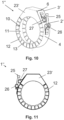
- Fig. 10
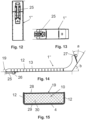
- eine perspektivische Ansicht der erfindungsgemäßen Haltevorrichtung, welche eine verschwenk- und einhängbare Schraube aufweist,
- Fig. 11
- eine Seitenansicht der Haltevorrichtung gemäß
Fig. 10 , - Fig. 12
- eine Ansicht der Haltevorrichtung gemäß
Fig. 10 und 11 , wobei die Schraubverbindung dargestellt ist, - Fig. 13
- eine weitere Ansicht der Haltevorrichtung gemäß
Fig. 12 , - Fig. 14
- eine Seitenansicht der aufgerollten und nicht geschlossenen Haltevorrichtung gemäß
Fig. 10 und - Fig. 15
- eine Schnittansicht einer zwischen den Seitenstegen eingelegten Isolierung.
- Die
Fig. 1 und9 zeigen jeweils eine Haltevorrichtung 1, 1' zum Befestigen einer Isolierung an einer V-Band-Schelle oder an einer anderen Verbindungsvorrichtung für zu verbindende Rohrenden, umfassend Verschlusselemente 2, 2', 3, 3', wobei durch Zusammenwirken der Verschlusselemente 2, 2', 3, 3' der Außen- und/ oder Innenumfang der Haltevorrichtung 1, 1' verringerbar ist. Beide Haltevorrichtungen 1, 1' umfassen einen biegbaren Gürtelabschnitt 4, der als Teil eines Außenmantels oder nach Art eines Außenmantels um eine Isolierung legbar ist. Der Gürtelabschnitt 4 ist mittelbar oder unmittelbar mit einer Haube 23, 23' zur Aufnahme eines Überstands oder Verschlusses einer V-Band-Schelle oder einer anderen Verbindungsvorrichtung für Rohrenden verbunden und/ oder verbindbar. - Die
Fig. 1 bis 6 zeigen eine Haltevorrichtung 1, bei welcher die beiden Verschlusselemente 2, 3 miteinander verbindbar oder verbunden sind, wobei das erste Verschlusselement 2 einen Zugkörper 5 aufweist oder als solcher ausgebildet ist, wobei das zweite Verschlusselement 3 eine Ausnehmung 6 aufweist, durch welche der Zugkörper 5 zur Verringerung des Außen- und/ oder Innenumfangs der Haltevorrichtung 1 durchziehbar oder durchgezogen ist, und wobei der Zugkörper 5 aufwickelbar oder aufgewickelt ist und beim Aufwickeln oder im aufgewickelten Zustand an einem Widerlager 8 anliegt. Das zweite Verschlusselement 3 ist als Haube 23 ausgebildet, wobei in der Haube 23 die Ausnehmung 6 ausgebildet ist. - Die
Fig. 1 bis 4 zeigen konkret eine Haltevorrichtung 1 zum Befestigen einer nicht gezeigten Isolierung, umfassend ein erstes Ende, dem ein erstes Verschlusselement 2 zugeordnet ist, ein zweites Ende, dem ein zweites Verschlusselement 3 zugeordnet ist, und einen biegbaren Gürtelabschnitt 4, welcher sich zwischen den Verschlusselementen 2, 3 erstreckt, wobei die beiden Enden durch ein Zusammenwirken der Verschlusselemente 2, 3 miteinander verbindbar oder verbunden sind, wobei das erste Verschlusselement 2 einen Zugkörper 5 aufweist und wobei das zweite Verschlusselement 3 eine Ausnehmung 6 aufweist, durch welche der Zugkörper 5 durchziehbar oder durchgezogen ist. - Die
Fig. 1 bis 3 zeigen, dass der Zugkörper 5 aufwickelbar ist und seine Außenfläche 7 beim Aufwickeln an einem Widerlager 8 des zweiten Verschlusselements 3 anliegt. Insoweit ist der Zugkörper 5 aufwickelbar und liegt beim Aufwickeln an dem Widerlager 8 an und stützt sich an diesem ab. -
Fig. 4 zeigt, dass der Zugkörper 5 aufgewickelt ist und seine Außenfläche 7 im aufgewickelten Zustand an einem Widerlager 8 des zweiten Verschlusselements 3 anliegt. Insoweit ist der Zugkörper 5 aufgewickelt und liegt im aufgewickelten Zustand an dem Widerlager 8 an und stützt sich an diesem ab.Fig. 4 zeigt konkret, dass der Zugkörper 5 spiralförmig aufgewickelt ist. - Der Zugkörper 5 gemäß
Fig. 1 bis 3 ist händisch oder mittels eines Akkuschraubers spiralförmig aufwickelbar und in den inFig. 4 gezeigten Zustand verbringbar. Hierfür ist der Zugkörper 5 als länglicher Streifen oder längliche Zunge oder streifenartig oder zungenartig ausgebildet. An seinem freien Ende weist er eine Einschnürung 9 auf, die ein leichtes Ergreifen und Umbiegen bzw. Aufwickeln durch ein Werkzeug erlaubt. Der Zugkörper 5 und das Material, aus dem der Gürtelabschnitt 4 und die gesamte Haltevorrichtung 1 gefertigt sind, weisen eine Dicke von 0,5 mm auf. - Die
Fig. 1 bis 5 zeigen, dass der Gürtelabschnitt 4 eine Aufnahme 10 zum Ein- oder Anlegen einer Isolierung aufweist und diese Aufnahme 10 ausbildet. Der Gürtelabschnitt 4 weist hierfür eine innere Anlagebasis 11 auf, von welcher beidseitig Stützsegmente 12 abragen, welche durch Aussparungen 13 voneinander beabstandet sind. Mindestens zwei Stützsegmente 12 verjüngen sich in Abragerichtung in ihrer Breite, wobei sich eine zwischen diesen liegende Aussparung 13 in Abragerichtung derart erweitert, dass sich die Stützsegmente 12 beim Biegen des Gürtelabschnitts 4 zur Verringerung des Außen- und/ oder Innenumfangs mit ihren Seitenkanten einander annähern können und sich die Aussparung 13 dabei in ihrer Weite verringert. - Die Stützsegmente 12 sind voneinander durch die Aussparungen 13 beabstandet. Die Stützsegmente 12 ragen von der Anlagebasis 11 ab, wobei sie mit dieser jeweils einen Winkel von 80 bis 100° einschließen. Dies ist in
Fig. 5 besonders deutlich dargestellt. Mehrere benachbarte Stützsegmente 12 sind jeweils an gegenüberliegenden Längsseiten der Anlagebasis 11 palisadenartig angeordnet. Zwischen zwei benachbarten Stützsegmenten 12 ist jeweils eine Aussparung 13 in Form eines einseitig offenen, sich V-förmig erweiternden Schlitzes ausgebildet. Die Aussparungen 13 können durch Stanzprozesse oder einen Laser eingebracht werden. -
Fig. 7 zeigt, dass die Haltevorrichtung 1 einstückig aus einer metallischen Lage ausgebildet ist. Die metallische Lage besteht aus Edelstahl. Die metallische Lage weist eine Dicke von 0,5 mm auf. Die inFig. 7 links gezeigten abragenden Seitenelemente können aufgrund einer durchgängigen Kantung gebogen und durch Nietverbindungen zum zweiten Verschlusselement 3 bzw. zur Haube 23 verbunden werden. Die Stützsegmente 12 können ebenfalls aufgrund der Kantung zur Ausbildung einer Aufnahme 10 umgebogen werden. Das erste Verschlusselement 2 und der Zugkörper 5 sind einstückig ausgebildet und gehen ineinander über. Der Zugkörper 5 mündet in das erste Verschlusselement 2, indem sich die Breite des Zugkörpers 5 vergrößert. Hierdurch kann der Zugkörper 5 nur mit einer gewissen Länge durch die Ausnehmung 6 gezogen werden. -
Fig. 8 zeigt in der linken Ansicht ein rotierbares stiftförmiges Werkzeug 14 zum Festlegen der Haltevorrichtung 1. Das Werkzeug 14 umfasst ein Greifende 15 mit einem einseitig offenen Schlitz 16, in welchen der Zugkörper 5 einschiebbar ist, und ein Adapterende 17, welches als Sechskant 18 ausgebildet ist. Das Greifende 15 dient dem Ergreifen und Aufwickeln des Zugkörpers 5. Das Adapterende 17 ist mit einem dreh- oder rotierbaren Futter verbindbar. Hierfür ist das Adapterende 17 mit einem Sechskant 18 versehen. Es ist jedoch auch denkbar, dass das Adapterende 17 anders ausgebildet ist, um gut von einem Werkzeug ergriffen werden zu können. - Mit dem zuvor beschriebenen Werkzeug 14 ist ein Verfahren zum Befestigen einer Isolierung 19 mittels der Haltevorrichtung 1 durchführbar, wobei das erste Ende der Haltevorrichtung 1, dem das erste Verschlusselement 2 zugeordnet ist, und das zweite Ende der Haltevorrichtung 1, dem das zweite Verschlusselement 3 zugeordnet ist, miteinander verbunden werden, wobei der Gürtelabschnitt 4, welcher sich zwischen den Verschlusselementen 2, 3 erstreckt, gebogen wird, wobei die beiden Enden durch ein Zusammenwirken der Verschlusselemente 2, 3 verbunden werden, indem der Zugkörper 5 des ersten Verschlusselements 2 durch die Ausnehmung 6 des zweiten Verschlusselements 3 gezogen wird, wobei der Zugkörper 5 zur Verringerung des Außen- und Innenumfangs der Haltevorrichtung 1 und zu deren Festlegung aufgewickelt wird und wobei seine Außenfläche 7 beim Aufwickeln oder im aufgewickelten Zustand an einem Widerlager 8 des zweiten Verschlusselements 3 anliegt. Das Aufwickeln erfolgt durch Drehen des Werkzeugs 14, dessen Schlitz 16 mit dem Zugkörper 5 in Eingriff ist.
-
Fig. 8 zeigt auf der rechten Seite in schematischer Ansicht eine Anordnung, umfassend zwei Rohrenden 20, 21, welche durch eine V-Band-Schelle 22 miteinander gasdicht und fest verbunden sind, wobei die V-Band-Schelle 22 von einer Isolierung 19 umfangen wird und wobei die Isolierung 19 in der Aufnahme 10 der Haltevorrichtung 1 aufgenommen ist. Die Haltevorrichtung 1 presst die Isolierung 19 radial gegen die V-Band-Schelle 22 und umfängt sowohl die V-Band-Schelle 22 als auch die Isolierung 19 in radialer und axialer Richtung nach Art eines Außenmantels. Die Isolierung 19 und die V-Band-Schelle 22 werden hierdurch vor Steinschlag geschützt, wenn die Anordnung beispielsweise an einem Unterboden eines Kraftfahrzeugs angeordnet ist. - Die Rohrenden 20, 21 sind jeweils zusätzlich noch durch einen Isoliermantel 24 isoliert, der jeweils innerhalb der Haltevorrichtung 1 endet, um eine nahezu vollständige Isoliertheit herzustellen. Die Isolierung 19 ist zumindest an einer Stelle mit der Haltevorrichtung 1 verbunden. Die Isolierung 19 ist am zweiten Verschlusselement 3 festgelegt.
- Bei der hier konkret gezeigten Haltevorrichtung 1 ist nur ein Zugkörper 5 vorgesehen. Durch Aufwickeln eines einzigen Zugkörpers 5 kann die Montage schnell durchgeführt werden. Die Ausnehmung 6 im zweiten Verschlusselement 3 ist als an vier Seiten umgebener Schlitz ausgebildet. So kann der Zugkörper 5 nicht seitlich ausweichen. Der Schlitz bzw. die Ausnehmung 6 ist länglich ausgebildet. Der Schlitz bzw. die Ausnehmung 6 ist so schmal, dass der Zugkörper 5 mit geringem Spiel hindurchführbar ist. Hierdurch kann der Zugkörper 5 nicht mehr durch den Schlitz bzw. die Ausnehmung 6 zurückgleiten, auch wenn er nur geringfügig, das heißt mit nur wenigen Wicklungen, aufgewickelt ist.
-
Fig. 9 zeigt eine Haltevorrichtung 1', bei der kein Zugkörper, sondern eine Schraube 25 verwendet wird, um die Verschlusselemente 2', 3' miteinander zu verbinden. Das zweite Verschlusselement 3' ist als Haube 23' ausgebildet. -
Fig. 10 bis 14 zeigen die erfindungsgemäße Haltevorrichtung 1", bei welcher die beiden Verschlusselemente 2', 3' durch eine Schraubverbindung miteinander verbunden sind. - Eine Schraube 25 ist mit einem gewindetragenden Schraubenende in einer Schrauben-Gegenaufnahme 26 aufgenommen, und die Schraube 25 ist zur Verringerung des Außen- und/ oder Innenumfangs der Haltevorrichtung 1" in die Schrauben-Gegenaufnahme 26 eindrehbar.
- Die Schraube 25 ist mit ihrem gewindetragenden Schraubenende in einer drehbaren Schrauben-Gegenaufnahme 26 aufgenommen und verschwenkbar.
- Die Schraube 25 ist mit einem freien Ende, welches einen Schraubenkopf aufweist, in ein Einhängelager 27 einhängbar. Nach dem Einhängen kann durch Eindrehen der Schraube 25 in die Schrauben-Gegenaufnahme 26 die Haltevorrichtung 1" gegen radial innenliegende Elemente angedrückt werden.
- Die drehbare Schrauben-Gegenaufnahme 26 ist dem Gürtelabschnitt 4 zugeordnet, nämlich an diesem festgelegt. Das Einhängelager 27 ist der Haube 23' zugeordnet, nämlich an dieser festgelegt.
-
Fig. 14 zeigt die Haltevorrichtung 1" in aufgerolltem Zustand mit eingelegter Isolierung 19. Es sind mit Bezug auf Flächenneigungen der Haube 23' zwei Winkel a und b von jeweils 55° gezeigt. -
Fig. 15 zeigt, dass die Isolierung 19 eine Laminierung 28 aufweist, welche der Anlagebasis 11 abgewandt und nach radial innen angeordnet ist. Die Laminierung 28 ist auf einem Isoliermaterial 30 aufgebracht. Die Isolierung 19 ist bereichsweise durch einen Klebstoff 29 mit der Haltevorrichtung 1" verbunden. - Die Haltevorrichtung 1" weist in ihrer Haube 23' eine Ausnehmung 6 auf, durch die ein Zugkörper 5 ziehbar wäre. Insoweit ist eine Kombination aus einer Schraubverbindung und einer Verbindung mittels des hier beschriebenen Zugkörpers 5 denkbar.
-
- 1, 1', 1"
- Haltevorrichtung
- 2, 2'
- erstes Verschlusselement
- 3, 3'
- zweites Verschlusselement
- 4
- Gürtelabschnitt
- 5
- Zugkörper
- 6
- Ausnehmung
- 7
- Außenfläche
- 8
- Widerlager
- 9
- Einschnürung
- 10
- Aufnahme
- 11
- Anlagebasis
- 12
- Stützsegment
- 13
- Aussparung
- 14
- Werkzeug
- 15
- Greifende
- 16
- Schlitz
- 17
- Adapterende
- 18
- Sechskant
- 19
- Isolierung
- 20, 21
- Rohrende
- 22
- V-Band-Schelle
- 23, 23`
- Haube
- 24
- Isoliermantel
- 25
- Schraube
- 26
- Schrauben-Gegenaufnahme
- 27
- Einhängelager
- 28
- Laminierung
- 29
- Klebstoff
- 30
- Isoliermaterial
Claims (7)
- Haltevorrichtung (1") zum Befestigen einer Isolierung (19) an einer V-Band-Schelle (22) oder an einer anderen Verbindungsvorrichtung für zu verbindende Rohrenden (20, 21), umfassend Verschlusselemente (2', 3'), wobei durch Zusammenwirken der Verschlusselemente (2', 3') der Außen- und/ oder Innenumfang der Haltevorrichtung (1") verringerbar ist, und umfassend einen biegbaren Gürtelabschnitt (4), wobei der Gürtelabschnitt (4) als Teil eines Außenmantels oder nach Art eines Außenmantels um eine Isolierung (19) legbar ist, wobei der Gürtelabschnitt (4) mittelbar oder unmittelbar mit einer Haube (23') zur Aufnahme eines Überstands oder Verschlusses einer V-Band-Schelle (22) oder einer anderen Verbindungsvorrichtung für Rohrenden (20, 21) verbunden ist,
dadurch gekennzeichnet, dass
die beiden Verschlusselemente (2', 3') durch eine Schraubverbindung miteinander verbunden sind, wobei eine Schraube (25) mit einem gewindetragenden Schraubenende in einer Schrauben-Gegenaufnahme (26) aufgenommen ist und die Schraube (25) zur Verringerung des Außen- und/ oder Innenumfangs der Haltevorrichtung (1") in die Schrauben-Gegenaufnahme (26) eindrehbar ist, wobei die Schraube (25) mit ihrem Schraubenende in der drehbaren Schrauben-Gegenaufnahme (26) aufgenommen oder verschwenkbar aufgenommen ist und mit einem freien Ende, welches einen Schraubenkopf aufweist, in ein Einhängelager (27) eingehängt ist, wobei die drehbare Schrauben-Gegenaufnahme (26) dem Gürtelabschnitt (4) zugeordnet ist und wobei das Einhängelager (27) der Haube (23') zugeordnet ist. - Haltevorrichtung nach Anspruch 1, dadurch gekennzeichnet, dass der Gürtelabschnitt (4) eine Aufnahme (10) zum Ein- oder Anlegen einer Isolierung (19) aufweist oder ausbildet, wobei der Gürtelabschnitt (4) eine innere Anlagebasis (11) aufweist, von welcher beidseitig Stützsegmente (12) abragen, welche durch Aussparungen (13) voneinander beabstandet sind.
- Haltevorrichtung nach Anspruch 2, dadurch gekennzeichnet, dass mindestens zwei Stützsegmente (12) sich in Abragerichtung in ihrer Breite verjüngen, wobei sich eine zwischen diesen liegende Aussparung (13) in Abragerichtung derart erweitert, dass sich die Stützsegmente (12) beim Biegen des Gürtelabschnitts (4) zur Verringerung des Außen- und/ oder Innenumfangs mit ihren Seitenkanten einander annähern können und sich die Aussparung (13) dabei in ihrer Weite verringert.
- Haltevorrichtung nach einem der voranstehenden Ansprüche, dadurch gekennzeichnet, dass eine Isolierung (19) zumindest an einer Stelle mit der Haltevorrichtung (1") verbunden ist und/ oder dass eine Isolierung (19) am zweiten Verschlusselement (3') festgelegt ist.
- Haltevorrichtung nach einem der voranstehenden Ansprüche, dadurch gekennzeichnet, dass die Isolierung (19) eine Laminierung (28) aufweist, welche der Anlagebasis (11) abgewandt und/ oder nach radial innen angeordnet ist.
- Haltevorrichtung nach einem der voranstehenden Ansprüche, dadurch gekennzeichnet, dass die Isolierung (19) bereichsweise durch einen Klebstoff (29) mit der Haltevorrichtung (1") verbunden ist.
- Haltevorrichtung nach einem der voranstehenden Ansprüche, dadurch gekennzeichnet, dass die Haube (23') eine Ausnehmung (6) aufweist, durch die ein Zugkörper (5) ziehbar ist.
Applications Claiming Priority (4)
| Application Number | Priority Date | Filing Date | Title |
|---|---|---|---|
| DE102016107637.6A DE102016107637A1 (de) | 2016-04-25 | 2016-04-25 | Haltevorrichtung zum Befestigen einer Isolierung und Werkzeug hierfür |
| DE202016002956.9U DE202016002956U1 (de) | 2016-04-25 | 2016-05-10 | Haltevorrichtung zum Befestigen einer lsolierung und Werkzeug hierfür |
| DE202016002955.0U DE202016002955U1 (de) | 2016-04-25 | 2016-05-10 | Haltevorrichtung zum Befestigen einer lsolierung und Werkzeug hierfür |
| EP17000616.7A EP3239586B1 (de) | 2016-04-25 | 2017-04-11 | Haltevorrichtung zum befestigen einer isolierung |
Related Parent Applications (2)
| Application Number | Title | Priority Date | Filing Date |
|---|---|---|---|
| EP17000616.7A Division EP3239586B1 (de) | 2016-04-25 | 2017-04-11 | Haltevorrichtung zum befestigen einer isolierung |
| EP17000616.7A Division-Into EP3239586B1 (de) | 2016-04-25 | 2017-04-11 | Haltevorrichtung zum befestigen einer isolierung |
Publications (2)
| Publication Number | Publication Date |
|---|---|
| EP3569916A1 EP3569916A1 (de) | 2019-11-20 |
| EP3569916B1 true EP3569916B1 (de) | 2023-02-22 |
Family
ID=56293371
Family Applications (2)
| Application Number | Title | Priority Date | Filing Date |
|---|---|---|---|
| EP19184309.3A Active EP3569916B1 (de) | 2016-04-25 | 2017-04-11 | Haltevorrichtung zum befestigen einer isolierung |
| EP17000616.7A Active EP3239586B1 (de) | 2016-04-25 | 2017-04-11 | Haltevorrichtung zum befestigen einer isolierung |
Family Applications After (1)
| Application Number | Title | Priority Date | Filing Date |
|---|---|---|---|
| EP17000616.7A Active EP3239586B1 (de) | 2016-04-25 | 2017-04-11 | Haltevorrichtung zum befestigen einer isolierung |
Country Status (3)
| Country | Link |
|---|---|
| US (1) | US10612706B2 (de) |
| EP (2) | EP3569916B1 (de) |
| DE (3) | DE102016107637A1 (de) |
Families Citing this family (8)
| Publication number | Priority date | Publication date | Assignee | Title |
|---|---|---|---|---|
| DE102016111117A1 (de) * | 2016-06-17 | 2017-12-21 | Norma Germany Gmbh | Schelle mit thermischer Isolationsschicht |
| GB2559412B (en) * | 2017-02-06 | 2019-05-15 | Ford Global Tech Llc | Heatshield for a band clamp |
| US11268635B2 (en) * | 2018-12-28 | 2022-03-08 | Commscope Technologies Llc | Devices and methods for holding cables |
| US11271378B2 (en) | 2018-12-28 | 2022-03-08 | Commscope Technologies Llc | Devices and methods for holding cables |
| DE102019121432A1 (de) | 2019-08-08 | 2021-02-11 | Norma Germany Gmbh | Schellenanordnung mit einer Hitzeschutzeinrichtung |
| CN110848505B (zh) * | 2019-12-20 | 2025-03-14 | 北京吉瑞普管道技术有限公司 | 一种遇火膨胀装置 |
| EP3992506B1 (de) | 2020-10-29 | 2024-07-17 | tmax Holding GmbH | Vorrichtung zur wärmeisolierung und zur wärmeabführung und kühlung |
| US11898669B2 (en) * | 2022-06-08 | 2024-02-13 | International Engine Intellectual Property Company, Llc | System for reducing band clamp failure |
Citations (1)
| Publication number | Priority date | Publication date | Assignee | Title |
|---|---|---|---|---|
| EP2241766A1 (de) * | 2009-04-14 | 2010-10-20 | Voss Industries, Inc. | Rohrschelle |
Family Cites Families (14)
| Publication number | Priority date | Publication date | Assignee | Title |
|---|---|---|---|---|
| US1467254A (en) * | 1921-02-21 | 1923-09-04 | Tarbet Albert | Self-locking milk-can cover |
| US2395745A (en) * | 1942-11-16 | 1946-02-26 | James T King | Joint and clamp construction |
| GB616170A (en) * | 1945-04-04 | 1949-01-18 | Fridolf Henning Brunnzell | A flexible band for producing protective covers |
| US4492393A (en) * | 1981-08-31 | 1985-01-08 | Parker Hannifin Corporation | Pipe restraint device |
| US4402113A (en) * | 1981-12-30 | 1983-09-06 | Communications Technology Corporation | Flexible clamp for hose, cable and the like |
| JPS59126807U (ja) * | 1983-02-07 | 1984-08-27 | 株式会社リコー | カ−トリツジシ−ルの開封具 |
| JPS6038992U (ja) * | 1983-08-25 | 1985-03-18 | 川崎重工業株式会社 | 伸縮管継手 |
| US5103609A (en) | 1990-11-15 | 1992-04-14 | Minnesota Mining & Manufacturing Company | Intumescable fire stop device |
| DE4325757A1 (de) | 1993-07-31 | 1995-02-02 | Gruenau Gmbh Chem Fab | Rohrschott mit einem um ein Rohr biegbaren Blechmantel |
| US6685229B2 (en) * | 2001-11-15 | 2004-02-03 | Mpdi | Hose and clamp assembly |
| JP4563158B2 (ja) * | 2004-12-03 | 2010-10-13 | 株式会社ミハマ | 締付けバンド |
| CN101968144B (zh) * | 2005-03-04 | 2012-07-04 | 诺玛美国控股有限责任公司 | T型螺栓夹具快速连接销 |
| DE102005057670B4 (de) * | 2005-12-01 | 2009-12-10 | J. Eberspächer GmbH & Co. KG | Rohrverbindung |
| DE102008034435B4 (de) * | 2008-07-24 | 2019-12-24 | Norma Germany Gmbh | Flammschutzeinrichtung für eine Rohrkupplung |
-
2016
- 2016-04-25 DE DE102016107637.6A patent/DE102016107637A1/de not_active Withdrawn
- 2016-05-10 DE DE202016002956.9U patent/DE202016002956U1/de not_active Expired - Lifetime
- 2016-05-10 DE DE202016002955.0U patent/DE202016002955U1/de not_active Expired - Lifetime
-
2017
- 2017-04-11 EP EP19184309.3A patent/EP3569916B1/de active Active
- 2017-04-11 EP EP17000616.7A patent/EP3239586B1/de active Active
- 2017-04-24 US US15/495,816 patent/US10612706B2/en active Active
Patent Citations (1)
| Publication number | Priority date | Publication date | Assignee | Title |
|---|---|---|---|---|
| EP2241766A1 (de) * | 2009-04-14 | 2010-10-20 | Voss Industries, Inc. | Rohrschelle |
Also Published As
| Publication number | Publication date |
|---|---|
| DE102016107637A1 (de) | 2017-10-26 |
| DE202016002955U1 (de) | 2016-06-14 |
| US20170307117A1 (en) | 2017-10-26 |
| EP3569916A1 (de) | 2019-11-20 |
| EP3239586A1 (de) | 2017-11-01 |
| DE202016002956U1 (de) | 2016-06-14 |
| EP3239586B1 (de) | 2019-08-28 |
| US10612706B2 (en) | 2020-04-07 |
Similar Documents
| Publication | Publication Date | Title |
|---|---|---|
| EP3239586B1 (de) | Haltevorrichtung zum befestigen einer isolierung | |
| EP2908039B1 (de) | Befestigungssystem | |
| DE10016069A1 (de) | Übertragungsleitungs-Aufhängevorrichtung | |
| EP2216457A2 (de) | Schienenanbindesystem mit einer Montageschiene und einem Anbindeteil zum Anbinden der Montageschiene an einem Träger | |
| DE112010002322T5 (de) | Selbst zentrierendes Klebeband | |
| DE102015004019A1 (de) | Schutzgitter; Verfahren zur Herstellung eines Schutzgitters für Lüfter | |
| EP2216575B1 (de) | Befestigungselement, Vorrichtung sowie Verfahren zum Befestigen eines flexiblen Rohres | |
| DE102019121432A1 (de) | Schellenanordnung mit einer Hitzeschutzeinrichtung | |
| DE4108852A1 (de) | Spannschelle mit einem an seinen raendern bereichsweise wellenfoermigen spannband | |
| EP2113699A1 (de) | Rohrschelle | |
| EP1950480B1 (de) | Rohrschelle | |
| DE4430770B4 (de) | Messfühler zur einfachen Befestigung an einem Rohr | |
| DE202015002378U1 (de) | Schutzgitter | |
| AT519600B1 (de) | Haltevorrichtung für ein kabel oder rohr | |
| DE102012110659B4 (de) | Zwischenstütze, Sicherungssysteme und Verfahren zum Anbringen einer Zwischenstütze | |
| EP3239576B1 (de) | Haltevorrichtung für ein kabel oder rohr | |
| DE29911104U1 (de) | Befestigungsvorrichtung für Rohrleitungen | |
| WO2023174847A1 (de) | Profilschelle | |
| EP3239577B1 (de) | Haltevorrichtung für ein kabel oder rohr | |
| DE4103701C1 (de) | ||
| DE102004054336B4 (de) | Anordnung und Verfahren zum Verbinden von rohrförmigen Elementen | |
| DE102012216726B4 (de) | Haltevorrichtung für Leitungselemente | |
| DE102008010434B4 (de) | Montagehilfe zur Herstellung einer Verbindung zwischen zwei Flanschen | |
| CH684115A5 (de) | Rohrhaltevorrichtung. | |
| EP1265020A2 (de) | Flexible Gasleitung |
Legal Events
| Date | Code | Title | Description |
|---|---|---|---|
| PUAI | Public reference made under article 153(3) epc to a published international application that has entered the european phase |
Free format text: ORIGINAL CODE: 0009012 |
|
| STAA | Information on the status of an ep patent application or granted ep patent |
Free format text: STATUS: THE APPLICATION HAS BEEN PUBLISHED |
|
| AC | Divisional application: reference to earlier application |
Ref document number: 3239586 Country of ref document: EP Kind code of ref document: P |
|
| AK | Designated contracting states |
Kind code of ref document: A1 Designated state(s): AL AT BE BG CH CY CZ DE DK EE ES FI FR GB GR HR HU IE IS IT LI LT LU LV MC MK MT NL NO PL PT RO RS SE SI SK SM TR |
|
| STAA | Information on the status of an ep patent application or granted ep patent |
Free format text: STATUS: REQUEST FOR EXAMINATION WAS MADE |
|
| 17P | Request for examination filed |
Effective date: 20200317 |
|
| RBV | Designated contracting states (corrected) |
Designated state(s): AL AT BE BG CH CY CZ DE DK EE ES FI FR GB GR HR HU IE IS IT LI LT LU LV MC MK MT NL NO PL PT RO RS SE SI SK SM TR |
|
| STAA | Information on the status of an ep patent application or granted ep patent |
Free format text: STATUS: EXAMINATION IS IN PROGRESS |
|
| 17Q | First examination report despatched |
Effective date: 20210311 |
|
| GRAP | Despatch of communication of intention to grant a patent |
Free format text: ORIGINAL CODE: EPIDOSNIGR1 |
|
| STAA | Information on the status of an ep patent application or granted ep patent |
Free format text: STATUS: GRANT OF PATENT IS INTENDED |
|
| INTG | Intention to grant announced |
Effective date: 20221031 |
|
| RAP1 | Party data changed (applicant data changed or rights of an application transferred) |
Owner name: TMAX HOLDING GMBH |
|
| GRAS | Grant fee paid |
Free format text: ORIGINAL CODE: EPIDOSNIGR3 |
|
| GRAA | (expected) grant |
Free format text: ORIGINAL CODE: 0009210 |
|
| STAA | Information on the status of an ep patent application or granted ep patent |
Free format text: STATUS: THE PATENT HAS BEEN GRANTED |
|
| AC | Divisional application: reference to earlier application |
Ref document number: 3239586 Country of ref document: EP Kind code of ref document: P |
|
| AK | Designated contracting states |
Kind code of ref document: B1 Designated state(s): AL AT BE BG CH CY CZ DE DK EE ES FI FR GB GR HR HU IE IS IT LI LT LU LV MC MK MT NL NO PL PT RO RS SE SI SK SM TR |
|
| REG | Reference to a national code |
Ref country code: GB Ref legal event code: FG4D Free format text: NOT ENGLISH |
|
| REG | Reference to a national code |
Ref country code: CH Ref legal event code: EP |
|
| REG | Reference to a national code |
Ref country code: DE Ref legal event code: R096 Ref document number: 502017014447 Country of ref document: DE |
|
| REG | Reference to a national code |
Ref country code: AT Ref legal event code: REF Ref document number: 1549723 Country of ref document: AT Kind code of ref document: T Effective date: 20230315 Ref country code: IE Ref legal event code: FG4D Free format text: LANGUAGE OF EP DOCUMENT: GERMAN |
|
| REG | Reference to a national code |
Ref country code: NL Ref legal event code: FP |
|
| REG | Reference to a national code |
Ref country code: SE Ref legal event code: TRGR |
|
| REG | Reference to a national code |
Ref country code: LT Ref legal event code: MG9D |
|
| P01 | Opt-out of the competence of the unified patent court (upc) registered |
Effective date: 20230417 |
|
| PG25 | Lapsed in a contracting state [announced via postgrant information from national office to epo] |
Ref country code: RS Free format text: LAPSE BECAUSE OF FAILURE TO SUBMIT A TRANSLATION OF THE DESCRIPTION OR TO PAY THE FEE WITHIN THE PRESCRIBED TIME-LIMIT Effective date: 20230222 Ref country code: PT Free format text: LAPSE BECAUSE OF FAILURE TO SUBMIT A TRANSLATION OF THE DESCRIPTION OR TO PAY THE FEE WITHIN THE PRESCRIBED TIME-LIMIT Effective date: 20230622 Ref country code: NO Free format text: LAPSE BECAUSE OF FAILURE TO SUBMIT A TRANSLATION OF THE DESCRIPTION OR TO PAY THE FEE WITHIN THE PRESCRIBED TIME-LIMIT Effective date: 20230522 Ref country code: LV Free format text: LAPSE BECAUSE OF FAILURE TO SUBMIT A TRANSLATION OF THE DESCRIPTION OR TO PAY THE FEE WITHIN THE PRESCRIBED TIME-LIMIT Effective date: 20230222 Ref country code: LT Free format text: LAPSE BECAUSE OF FAILURE TO SUBMIT A TRANSLATION OF THE DESCRIPTION OR TO PAY THE FEE WITHIN THE PRESCRIBED TIME-LIMIT Effective date: 20230222 Ref country code: HR Free format text: LAPSE BECAUSE OF FAILURE TO SUBMIT A TRANSLATION OF THE DESCRIPTION OR TO PAY THE FEE WITHIN THE PRESCRIBED TIME-LIMIT Effective date: 20230222 Ref country code: ES Free format text: LAPSE BECAUSE OF FAILURE TO SUBMIT A TRANSLATION OF THE DESCRIPTION OR TO PAY THE FEE WITHIN THE PRESCRIBED TIME-LIMIT Effective date: 20230222 |
|
| PG25 | Lapsed in a contracting state [announced via postgrant information from national office to epo] |
Ref country code: PL Free format text: LAPSE BECAUSE OF FAILURE TO SUBMIT A TRANSLATION OF THE DESCRIPTION OR TO PAY THE FEE WITHIN THE PRESCRIBED TIME-LIMIT Effective date: 20230222 Ref country code: IS Free format text: LAPSE BECAUSE OF FAILURE TO SUBMIT A TRANSLATION OF THE DESCRIPTION OR TO PAY THE FEE WITHIN THE PRESCRIBED TIME-LIMIT Effective date: 20230622 Ref country code: GR Free format text: LAPSE BECAUSE OF FAILURE TO SUBMIT A TRANSLATION OF THE DESCRIPTION OR TO PAY THE FEE WITHIN THE PRESCRIBED TIME-LIMIT Effective date: 20230523 Ref country code: FI Free format text: LAPSE BECAUSE OF FAILURE TO SUBMIT A TRANSLATION OF THE DESCRIPTION OR TO PAY THE FEE WITHIN THE PRESCRIBED TIME-LIMIT Effective date: 20230222 |
|
| PG25 | Lapsed in a contracting state [announced via postgrant information from national office to epo] |
Ref country code: SM Free format text: LAPSE BECAUSE OF FAILURE TO SUBMIT A TRANSLATION OF THE DESCRIPTION OR TO PAY THE FEE WITHIN THE PRESCRIBED TIME-LIMIT Effective date: 20230222 Ref country code: RO Free format text: LAPSE BECAUSE OF FAILURE TO SUBMIT A TRANSLATION OF THE DESCRIPTION OR TO PAY THE FEE WITHIN THE PRESCRIBED TIME-LIMIT Effective date: 20230222 Ref country code: EE Free format text: LAPSE BECAUSE OF FAILURE TO SUBMIT A TRANSLATION OF THE DESCRIPTION OR TO PAY THE FEE WITHIN THE PRESCRIBED TIME-LIMIT Effective date: 20230222 Ref country code: DK Free format text: LAPSE BECAUSE OF FAILURE TO SUBMIT A TRANSLATION OF THE DESCRIPTION OR TO PAY THE FEE WITHIN THE PRESCRIBED TIME-LIMIT Effective date: 20230222 Ref country code: CZ Free format text: LAPSE BECAUSE OF FAILURE TO SUBMIT A TRANSLATION OF THE DESCRIPTION OR TO PAY THE FEE WITHIN THE PRESCRIBED TIME-LIMIT Effective date: 20230222 |
|
| REG | Reference to a national code |
Ref country code: DE Ref legal event code: R097 Ref document number: 502017014447 Country of ref document: DE |
|
| PG25 | Lapsed in a contracting state [announced via postgrant information from national office to epo] |
Ref country code: SK Free format text: LAPSE BECAUSE OF FAILURE TO SUBMIT A TRANSLATION OF THE DESCRIPTION OR TO PAY THE FEE WITHIN THE PRESCRIBED TIME-LIMIT Effective date: 20230222 |
|
| PG25 | Lapsed in a contracting state [announced via postgrant information from national office to epo] |
Ref country code: LU Free format text: LAPSE BECAUSE OF NON-PAYMENT OF DUE FEES Effective date: 20230411 |
|
| PLBE | No opposition filed within time limit |
Free format text: ORIGINAL CODE: 0009261 |
|
| STAA | Information on the status of an ep patent application or granted ep patent |
Free format text: STATUS: NO OPPOSITION FILED WITHIN TIME LIMIT |
|
| REG | Reference to a national code |
Ref country code: BE Ref legal event code: MM Effective date: 20230430 |
|
| PG25 | Lapsed in a contracting state [announced via postgrant information from national office to epo] |
Ref country code: MC Free format text: LAPSE BECAUSE OF FAILURE TO SUBMIT A TRANSLATION OF THE DESCRIPTION OR TO PAY THE FEE WITHIN THE PRESCRIBED TIME-LIMIT Effective date: 20230222 |
|
| 26N | No opposition filed |
Effective date: 20231123 |
|
| PG25 | Lapsed in a contracting state [announced via postgrant information from national office to epo] |
Ref country code: SI Free format text: LAPSE BECAUSE OF FAILURE TO SUBMIT A TRANSLATION OF THE DESCRIPTION OR TO PAY THE FEE WITHIN THE PRESCRIBED TIME-LIMIT Effective date: 20230222 Ref country code: MC Free format text: LAPSE BECAUSE OF FAILURE TO SUBMIT A TRANSLATION OF THE DESCRIPTION OR TO PAY THE FEE WITHIN THE PRESCRIBED TIME-LIMIT Effective date: 20230222 |
|
| REG | Reference to a national code |
Ref country code: IE Ref legal event code: MM4A |
|
| PG25 | Lapsed in a contracting state [announced via postgrant information from national office to epo] |
Ref country code: BE Free format text: LAPSE BECAUSE OF NON-PAYMENT OF DUE FEES Effective date: 20230430 |
|
| PG25 | Lapsed in a contracting state [announced via postgrant information from national office to epo] |
Ref country code: IE Free format text: LAPSE BECAUSE OF NON-PAYMENT OF DUE FEES Effective date: 20230411 |
|
| PG25 | Lapsed in a contracting state [announced via postgrant information from national office to epo] |
Ref country code: IE Free format text: LAPSE BECAUSE OF NON-PAYMENT OF DUE FEES Effective date: 20230411 |
|
| PG25 | Lapsed in a contracting state [announced via postgrant information from national office to epo] |
Ref country code: BG Free format text: LAPSE BECAUSE OF FAILURE TO SUBMIT A TRANSLATION OF THE DESCRIPTION OR TO PAY THE FEE WITHIN THE PRESCRIBED TIME-LIMIT Effective date: 20230222 |
|
| PG25 | Lapsed in a contracting state [announced via postgrant information from national office to epo] |
Ref country code: BG Free format text: LAPSE BECAUSE OF FAILURE TO SUBMIT A TRANSLATION OF THE DESCRIPTION OR TO PAY THE FEE WITHIN THE PRESCRIBED TIME-LIMIT Effective date: 20230222 |
|
| PGFP | Annual fee paid to national office [announced via postgrant information from national office to epo] |
Ref country code: NL Payment date: 20250422 Year of fee payment: 9 |
|
| PGFP | Annual fee paid to national office [announced via postgrant information from national office to epo] |
Ref country code: DE Payment date: 20250417 Year of fee payment: 9 |
|
| PGFP | Annual fee paid to national office [announced via postgrant information from national office to epo] |
Ref country code: IT Payment date: 20250430 Year of fee payment: 9 |
|
| PGFP | Annual fee paid to national office [announced via postgrant information from national office to epo] |
Ref country code: FR Payment date: 20250425 Year of fee payment: 9 |
|
| PGFP | Annual fee paid to national office [announced via postgrant information from national office to epo] |
Ref country code: CH Payment date: 20250501 Year of fee payment: 9 |
|
| PGFP | Annual fee paid to national office [announced via postgrant information from national office to epo] |
Ref country code: AT Payment date: 20250416 Year of fee payment: 9 |
|
| PG25 | Lapsed in a contracting state [announced via postgrant information from national office to epo] |
Ref country code: CY Free format text: LAPSE BECAUSE OF FAILURE TO SUBMIT A TRANSLATION OF THE DESCRIPTION OR TO PAY THE FEE WITHIN THE PRESCRIBED TIME-LIMIT; INVALID AB INITIO Effective date: 20170411 |
|
| PGFP | Annual fee paid to national office [announced via postgrant information from national office to epo] |
Ref country code: SE Payment date: 20250423 Year of fee payment: 9 |
|
| PG25 | Lapsed in a contracting state [announced via postgrant information from national office to epo] |
Ref country code: HU Free format text: LAPSE BECAUSE OF FAILURE TO SUBMIT A TRANSLATION OF THE DESCRIPTION OR TO PAY THE FEE WITHIN THE PRESCRIBED TIME-LIMIT; INVALID AB INITIO Effective date: 20170411 |
|
| PG25 | Lapsed in a contracting state [announced via postgrant information from national office to epo] |
Ref country code: TR Free format text: LAPSE BECAUSE OF FAILURE TO SUBMIT A TRANSLATION OF THE DESCRIPTION OR TO PAY THE FEE WITHIN THE PRESCRIBED TIME-LIMIT Effective date: 20230222 |
|
| REG | Reference to a national code |
Ref country code: DE Ref legal event code: R082 Ref document number: 502017014447 Country of ref document: DE Representative=s name: WESCH, ARNO, DR. RER. NAT., DE |
|
| PGFP | Annual fee paid to national office [announced via postgrant information from national office to epo] |
Ref country code: GB Payment date: 20260324 Year of fee payment: 10 |
|
| REG | Reference to a national code |
Ref country code: CH Ref legal event code: U11 Free format text: ST27 STATUS EVENT CODE: U-0-0-U10-U11 (AS PROVIDED BY THE NATIONAL OFFICE) Effective date: 20260501 |