EP1950480B1 - Rohrschelle - Google Patents
Rohrschelle Download PDFInfo
- Publication number
- EP1950480B1 EP1950480B1 EP20080100533 EP08100533A EP1950480B1 EP 1950480 B1 EP1950480 B1 EP 1950480B1 EP 20080100533 EP20080100533 EP 20080100533 EP 08100533 A EP08100533 A EP 08100533A EP 1950480 B1 EP1950480 B1 EP 1950480B1
- Authority
- EP
- European Patent Office
- Prior art keywords
- opening
- flange
- clamp
- fact
- take
- Prior art date
- Legal status (The legal status is an assumption and is not a legal conclusion. Google has not performed a legal analysis and makes no representation as to the accuracy of the status listed.)
- Active
Links
- 238000003780 insertion Methods 0.000 claims description 16
- 230000037431 insertion Effects 0.000 claims description 16
- 239000000758 substrate Substances 0.000 description 4
- 229910000639 Spring steel Inorganic materials 0.000 description 1
- 238000005452 bending Methods 0.000 description 1
- 238000011161 development Methods 0.000 description 1
- 230000018109 developmental process Effects 0.000 description 1
- 238000006073 displacement reaction Methods 0.000 description 1
- 230000014759 maintenance of location Effects 0.000 description 1
- 238000004519 manufacturing process Methods 0.000 description 1
- 239000000463 material Substances 0.000 description 1
- 239000002184 metal Substances 0.000 description 1
- 238000000034 method Methods 0.000 description 1
Images

Classifications
-
- F—MECHANICAL ENGINEERING; LIGHTING; HEATING; WEAPONS; BLASTING
- F16—ENGINEERING ELEMENTS AND UNITS; GENERAL MEASURES FOR PRODUCING AND MAINTAINING EFFECTIVE FUNCTIONING OF MACHINES OR INSTALLATIONS; THERMAL INSULATION IN GENERAL
- F16L—PIPES; JOINTS OR FITTINGS FOR PIPES; SUPPORTS FOR PIPES, CABLES OR PROTECTIVE TUBING; MEANS FOR THERMAL INSULATION IN GENERAL
- F16L3/00—Supports for pipes, cables or protective tubing, e.g. hangers, holders, clamps, cleats, clips, brackets
- F16L3/08—Supports for pipes, cables or protective tubing, e.g. hangers, holders, clamps, cleats, clips, brackets substantially surrounding the pipe, cable or protective tubing
- F16L3/10—Supports for pipes, cables or protective tubing, e.g. hangers, holders, clamps, cleats, clips, brackets substantially surrounding the pipe, cable or protective tubing divided, i.e. with two or more members engaging the pipe, cable or protective tubing
- F16L3/11—Supports for pipes, cables or protective tubing, e.g. hangers, holders, clamps, cleats, clips, brackets substantially surrounding the pipe, cable or protective tubing divided, i.e. with two or more members engaging the pipe, cable or protective tubing and hanging from a pendant
-
- F—MECHANICAL ENGINEERING; LIGHTING; HEATING; WEAPONS; BLASTING
- F16—ENGINEERING ELEMENTS AND UNITS; GENERAL MEASURES FOR PRODUCING AND MAINTAINING EFFECTIVE FUNCTIONING OF MACHINES OR INSTALLATIONS; THERMAL INSULATION IN GENERAL
- F16L—PIPES; JOINTS OR FITTINGS FOR PIPES; SUPPORTS FOR PIPES, CABLES OR PROTECTIVE TUBING; MEANS FOR THERMAL INSULATION IN GENERAL
- F16L3/00—Supports for pipes, cables or protective tubing, e.g. hangers, holders, clamps, cleats, clips, brackets
- F16L3/08—Supports for pipes, cables or protective tubing, e.g. hangers, holders, clamps, cleats, clips, brackets substantially surrounding the pipe, cable or protective tubing
- F16L3/10—Supports for pipes, cables or protective tubing, e.g. hangers, holders, clamps, cleats, clips, brackets substantially surrounding the pipe, cable or protective tubing divided, i.e. with two or more members engaging the pipe, cable or protective tubing
- F16L3/1008—Supports for pipes, cables or protective tubing, e.g. hangers, holders, clamps, cleats, clips, brackets substantially surrounding the pipe, cable or protective tubing divided, i.e. with two or more members engaging the pipe, cable or protective tubing with two members engaging the pipe, cable or tubing, both being made of thin band material completely surrounding the pipe
- F16L3/1016—Supports for pipes, cables or protective tubing, e.g. hangers, holders, clamps, cleats, clips, brackets substantially surrounding the pipe, cable or protective tubing divided, i.e. with two or more members engaging the pipe, cable or protective tubing with two members engaging the pipe, cable or tubing, both being made of thin band material completely surrounding the pipe the members being joined by means of two screws
Definitions
- the invention relates to a pipe clamp with a first and a second clamp bracket, which are connected to each other by means of two clamping screws via two flanges, two flanges having an opening for the clamping screws, a flange with the opening opposite flange a laterally open insertion opening and the other flange having a flange opposite the opening has a passage opening which has a dimension extending in a plane spanned by the clamping screws and having a clearance which exceeds the diameter of the clamping screw.
- Such a clamp serves the fixation and retention of lines, such.
- lines such as pipes, cables or the like, on a substrate or on a support by means of a fastener, such as a threaded rod.
- a pipe clamp with a first and a second clamp bracket is known, which are connected to one another via each projecting at their ends flanges by means of two clamping screws.
- the two flanges of the first clamp bracket each have an opening with internal thread for the clamping screws.
- On the first clamp bracket is further provided a connection head for fixing the pipe clamp to a substrate or carrier by means of a fastener.
- a flange of the second clamp bracket has a laterally open insertion opening and the other flange has a passage opening in the form of a slot, wherein the dimension in the plane spanned by the clamping screws has a level exceeding the diameter of the clamping screw inside diameter.
- the second, not fixed to the substrate or to the carrier clamp bracket is laterally pivotable about a guided through the lead-through clamping screw longitudinal axis.
- a disadvantage of the known solution is that in a non-hanging assembly before the final clamping of the clamp bracket against each other, the closed pipe clamp can open unintentionally. In addition, the handling of such pipe clamps, especially in confined spaces consuming.
- the object of the invention is to provide a pipe clamp which has a high security against unwanted opening in different orientations and is easy to operate.
- the clamping screw guided through the lead-through opening is elastically held by a spring-elastic element in the lead-through opening.
- the spring-elastic element is advantageously fixed to at least one of the clamp bracket substantially immovable.
- the resilient element is made of a rubber or a spring steel.
- the insertion opening advantageously has an inner undercut for receiving a portion of the shaft of the clamping screw serving as a closure means.
- the resilient element is designed such that due to the resilient element and / or friction between the resilient element and the clamping screw of the pivotable clamp bracket is held for the assembly of the line to be determined until manual pivoting in the open pivot position.
- the clamping screw inserted into the insertion remains in an unfavorable mounting position and a readjustment of the line to be determined in the closed state of the clamp in the undercut.
- an audible perceptible signal advantageously occurs, which informs the user of the correct alignment of the clamp stirrup with respect to one another prior to the tightening thereof.
- the resilient element is a band portion which surrounds at least partially the tensioning screw and one of the clamp brackets. For example, engage around two free ends of the band, a free end of a flange, wherein the portion connecting the two ends, facing the flange with the insertion slot, engages around the clamping screw guided through the through opening.
- the band exerts a restoring force on it.
- the passage opening is formed for example as a slot whose longer dimension extends in the plane spanned by the clamping screws level.
- the band portion is circumferentially closed and thus easy to manufacture and assemble.
- the resilient element is sleeve-shaped and arranged in the passage opening.
- the sleeve-shaped, resilient element may for example have a round, oval or polygonal outer contour.
- the passage opening is formed, for example, as a round opening or as an elongated hole, wherein a dimension whose clear width exceeds the diameter of the corresponding clamping screw extends in the plane spanned by the clamping screws level.
- the resilient element has a radially extending groove for at least partially encompassing the edge of the lead-through opening, so that it can be secured in the through-opening in the flange in a form-fitting manner.
- the passage opening with the resilient element and the insertion opening are provided on the flanges of a clamp bracket.
- one of the clamp bracket on both flanges for example, the same openings z. B. with an internal thread for the clamping screws.
- the other clamp bracket has the passage opening for the arrangement of the resilient element on a flange and the one-sided open insertion opening on the other flange.
- the clamp is made of sheet metal in a stamping / bending process, for example, from a flat material.
- the in the FIGS. 1 to 3 illustrated clamp 11 has a first clamp bracket 12 with a curvature of the clamp bracket 12 forming substantially semicircular curved portion 13, at each of whose ends a flange 14 and 15 protrudes curvature side or radially outward.
- a connection head 16 for fixing the pipe clamp 11 to a substrate or carrier by means of a fastening element (not shown here) is arranged radially outwardly.
- an opening 17 is provided with a circumferential collar and an internal thread 18 for the clamping screws 6 and 7, respectively.
- the pipe clamp 11 further comprises a second clamp bracket 22 with a curvature forming a substantially semicircular curved portion 23, at its ends in each case a flange 24 and 25 curvature side or radially outward protrudes.
- a laterally open insertion opening 26 is provided with an undercut 27 for the clamping screw 7.
- a through opening 28 is provided for the clamping screw 6, which has a larger diameter than dimension F as the diameter D of the clamping screw 6.
- the through-opening 28 has a dimension F running in a plane E spanned by the clamping screws 6 and 7 and having a clear width exceeding the diameter D of the clamping screw 6.
- the second clamp bracket 22 is pivotable about a longitudinal axis 8 of the clamping screw 6 and in a certain range transverse to this longitudinal axis 8 to the first clamp bracket 12.
- a sleeve-shaped, resilient element 31 is arranged, which elastically holds the clamping screw 6 guided through the through-opening 28 in the through-opening 28.
- the resilient element 31 acts inter alia in the plane defined by the clamping screws 6 and 7 plane E.
- the resilient element 31 has a radially extending groove 32 for gripping the edge of the passage opening 28 in the flange 24 in regions.
- the second clamp bracket 22 is pivoted about the longitudinal axis 8 of the clamping screw 6 until the area of the flange 25 comes into abutment with the insertion opening 26 with the clamping screw 7.
- the resilient element 31 is partially compressed and the second clamp bracket 22 displaced by a maximum amount X in the plane defined by the clamping screws 6 and 7 plane E in the direction of arrow 33.
- the amount X is selected such that it is greater than or equal to the amount of the difference Z between the insertion axis 29 of the insertion opening 26 and the axis of the clamping screw 7, if this is located in the undercut 27 of the insertion opening 26. If the pressure on the second clamp bracket 22 is released, the resilient element 31 expands again and the clamping screw 7 is securely held in the insertion opening 26.
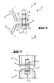
- FIGS. 4 and 5 only shown in a section pipe clamp 41 has a first clamp bracket 42 with a projecting flange 44 having an opening 47 with a circumferential collar and an internal thread for the clamping screw 6. Further, the clamp 41 has a second clamp bracket 52 with a projecting flange 54, in which a slot is provided as a passage opening 58 for the clamping screw 6.
- the passage opening 58 has a in one of the clamping screws 6 and 7 spanned plane extending dimension G, which has a diameter D of the clamping screw 6 exceeding clear width.
- the clamp 41 comprises a resilient element 61 in the form of a circumferentially closed band portion which surrounds the clamping screw 6 guided through the passage opening 58 and on the other hand, the free end of the flange 54 of the second clamp strap 52 and thereby elastically holds the clamping screw 6 in the passage opening 58 ,
- the resilient element 61 acts in the plane defined by the clamping screws 6 and 7 level E.
Landscapes
- Engineering & Computer Science (AREA)
- General Engineering & Computer Science (AREA)
- Mechanical Engineering (AREA)
- Clamps And Clips (AREA)
Description
- Die Erfindung betrifft eine Rohrschelle mit einem ersten und einem zweiten Schellenbügel, die über jeweils an ihren Enden abragende Flansche mittels zwei Spannschrauben miteinander verbindbar sind, wobei zwei Flansche eine Öffnung für die Spannschrauben aufweisen, ein einem Flansch mit der Öffnung gegenüberliegender Flansch eine seitlich offene Einführöffnung aufweist und der andere einem Flansch mit der Öffnung gegenüberliegende Flansch eine Durchführöffnung aufweist, die eine in einer von den Spannschrauben aufgespannten Ebene verlaufende Abmessung mit einer den Durchmesser der Spannschraube übersteigenden lichten Weite aufweist.
- Eine derartige Rohrschelle dient der Fixierung und Halterung von Leitungen, wie z. B. von Rohren, Kabeln oder dergleichen, an einem Untergrund oder an einem Träger mittels eines Befestigungselementes, wie beispielsweise einer Gewindestange.
- Aus der
DE 296 02 102 U1 ist eine Rohrschelle mit einem ersten und einem zweiten Schellenbügel bekannt, die über jeweils an ihren Enden abragende Flansche mittels zwei Spannschrauben miteinander verbindbar sind. Die beiden Flansche des ersten Schellenbügels weisen jeweils eine Öffnung mit Innengewinde für die Spannschrauben auf. An dem ersten Schellenbügel ist weiter ein Anschlusskopf zur Befestigung der Rohrschelle an einem Untergrund oder Träger mittels eines Befestigungselements vorgesehen. Ein Flansch des zweiten Schellenbügels weist eine seitlich offene Einführöffnung und der andere Flansch weist eine Durchführöffnung in Form eines Langlochs auf, wobei dessen Abmessung in der von den Spannschrauben aufgespannten Ebene eine den Durchmesser der Spannschraube übersteigende lichte Weite aufweist. Der zweite, nicht am Untergrund beziehungsweise am Träger festgelegte Schellenbügel ist um eine durch die Durchführöffnung hindurchgeführte Spannschraube verlaufende Längsachse seitlich verschwenkbar. - Nachteilig an der bekannten Lösung ist, dass bei einer nicht-hängenden Montage vor dem endgültigen Verspannen der Schellenbügel gegeneinander sich die geschlossene Rohrschelle ungewollt öffnen kann. Zudem ist das Handling solcher Rohrschellen insbesondere bei beengten Platzverhältnissen aufwändig.
- Aufgabe der Erfindung ist es, eine Rohrschelle zu schaffen, die in verschiedenen Ausrichtungen eine hohe Sicherheit gegen ungewolltes Öffnen aufweist und dabei einfach betätigbar ist.
- Die Aufgabe ist durch die Merkmale des unabhängigen Anspruchs gelöst. Vorteilhafte Weiterbildungen sind in den Unteransprüchen dargelegt.
- Gemäss der Erfindung ist die durch die Durchführöffnung hindurchgeführte Spannschraube von einem federelastischen Element in der Durchführöffnung elastisch gehalten.
- Beim Verschwenken oder Verschieben des einen Schellenbügels zu dem anderen Schellenbügel wird von dem federelastischen Element eine Rückstellkraft entgegen der Richtung zur Einführöffnung am anderen Flansch beziehungsweise am anderen Ende des entsprechenden Schellenbügels erzeugt. Das federelastische Element ist vorteilhaft an zumindest einem der Schellenbügel im Wesentlichen unverschieblich festgelegt. Beispielsweise ist das federelastische Element aus einem Gummi oder aus einem Federstahl gefertigt.
- Die Einführöffnung weist vorteilhaft einen innenliegenden Hinterschnitt zur Aufnahme eines Abschnitts des Schafts der als Verschlussmittel dienenden Spannschraube auf. Mit dem federelastischen Element bleibt die erforderliche Verschiebung des einen Schellenbügels zum anderen Schellenbügel entlang der von den Spannschrauben aufgespannten Ebene zur Überbrückung der Distanz zwischen der Einführachse und der Achse der Spannschraube in der hintergriffenen Position gewährleistet. Zudem ist das federelastische Element vorteilhaft derart ausgebildet, dass ein zum anderen Schellenbügel verschwenkter Schellenbügel von dem federelastischen Element in die Einschwenkstellung gezwungen wird.
- Alternativ ist das federelastische Element derart ausgebildet, dass aufgrund des federelastischen Elementes und/oder einer Reibung zwischen dem federelastischen Element und der Spannschraube der verschwenkbare Schellenbügel für die Montage der festzulegenden Leitung bis zum manuellen Verschwenken in der offenen Verschwenkstellung gehalten wird.
- Durch die von dem federelastischen Element erzeugte Kraft auf die Schellenbügel verbleibt die in die Einführöffnung eingeführte Spannschraube auch in einer ungünstigen Montageposition sowie bei einer Nachjustierung der festzulegenden Leitung im geschlossenen Zustand der Rohrschelle im Hinterschnitt. Vorteilhaft tritt beim Schliessen der Rohrschelle ein akustisches wahrnehmbares Signal auf, welches dem Anwender die korrekte Ausrichtung der Schellenbügel zueinander vor dem Verspannen derselben gegeneinander mitteilt.
- Bevorzugt ist das federelastische Element ein Bandabschnitt, der die Spannschraube und einen der Schellenbügel zumindest bereichsweise umgibt. Beispielsweise umgreifen zwei freie Enden des Bandes ein freies Ende eines Flansches, wobei der die beiden Enden verbindende Abschnitt, dem Flansch mit dem Einführschlitz zugewandt, die durch die Durchführöffnung hindurchgeführte Spannschraube umgreift. Bei einem Verschwenken oder Verschieben des bereichsweise von dem Band umfassten Schellenbügels übt das Band eine Rückstellkraft auf diesen aus. Die Durchführöffnung ist beispielsweise als Langloch ausgebildet, dessen längere Abmessung in der von den Spannschrauben aufgespannten Ebene verläuft.
- Vorzugsweise ist der Bandabschnitt umfänglich geschlossen und somit einfach herstellbar sowie montierbar.
- In einer weiteren bevorzugten Ausgestaltung der Erfindung ist das federelastische Element hülsenförmig ausgebildet und in der Durchführöffnung angeordnet. Das hülsenförmige, federelastische Element kann beispielsweise eine runde, ovale oder polygonale Aussenkontur aufweisen. Bei einem Verschwenken oder Verschieben der Schellenbügel zueinander wird das federelastische Element bereichsweise komprimiert und übt dadurch eine in der von den Spannschrauben aufgespannte Ebene wirkende Rückstellkraft auf den mit dem federelastischen Element versehenen Schellenbügel aus. Die Durchführöffnung ist beispielsweise als runde Öffnung oder als Langloch ausgebildet, wobei eine Abmessung, deren lichte Weite den Durchmesser der entsprechenden Spannschraube übersteigt, in der von den Spannschrauben aufgespannten Ebene verläuft.
- Vorzugsweise weist das federelastische Element eine radial verlaufende Nut zum zumindest bereichsweisen Umgreifen des Randes der Durchführöffnung auf, so dass dieses formschlüssig in der Durchführöffnung im Flansch festlegbar ist.
- Vorzugsweise sind die Durchführöffnung mit dem federelastischen Element und die Einführöffnung an den Flanschen eines Schellenbügels vorgesehen. Somit weist einer der Schellenbügel an beiden Flanschen beispielsweise die gleichen Öffnungen z. B. mit einem Innengewinde für die Spannschrauben auf. Der andere Schellenbügel weist die Durchführöffnung zur Anordnung des federelastischen Elementes an einem Flansch und die einseitig offene Einführöffnung am anderen Flansch auf.
- Vorteilhaft ist der Schellen bügel aus Blech in einem Stanz-/Biegeverfahren beispielsweise aus einem Flachmaterial gefertigt.
- Die Erfindung wird nachstehend anhand zweier Ausführungsbeispiele näher erläutert. Es zeigen:
- Fig. 1
- Eine Seitenansicht auf ein erstes Beispiel einer erfindungsgemässen Rohrschelle;
- Fig. 2
- einen Schnitt in vergrösserter Detaildarstellung gem. Detail II in
Fig. 1 ; - Fig. 3
- den zweiten Schellenbügel der Rohrschelle im Grundriss zum Teil geschnitten gem. Linie III-III in
Fig. 1 ; - Fig. 4
- eine Detailansicht eines zweiten Ausführungsbeispiels; und
- Fig. 5
- eine Ansicht gem. Linie V-V in
Fig. 4 . - Grundsätzlich sind in den Figuren gleiche Teile mit den gleichen Bezugszeichen versehen.
- Die in den
Figuren 1 bis 3 dargestellte Rohrschelle 11 weist einen ersten Schellenbügel 12 mit einem eine Krümmung des Schellenbügels 12 ausbildenden im Wesentlichen halbkreisförmig gebogenen Abschnitt 13 auf, an dessen Enden jeweils ein Flansch 14 und 15 krümmungsseitig beziehungsweise radial nach aussen abragt. In der Mitte des gebogenen Abschnitts 13 ist radial aussen ein Anschlusskopf 16 zur Befestigung der Rohrschelle 11 an einem Untergrund oder Träger mittels einem Befestigungselementes (hier nicht dargestellt) angeordnet. In den Flanschen 14 und 15 ist jeweils eine Öffnung 17 mit einem umlaufenden Bund und einem Innengewinde 18 für die Spannschrauben 6 und 7 vorgesehen. - Die Rohrschelle 11 weist weiter einen zweiten Schellenbügel 22 mit einem eine Krümmung ausbildenden im Wesentlichen halbkreisförmig gebogenen Abschnitt 23 auf, an dessen Enden jeweils ein Flansch 24 und 25 krümmungsseitig beziehungsweise radial nach aussen abragt. In dem Flansch 25 ist eine seitlich offene Einführöffnung 26 mit einem Hinterschnitt 27 für die Spannschraube 7 vorgesehen. In dem Flansch 24 ist eine Durchführöffnung 28 für die Spannschraube 6 vorgesehen, die einen grösseren Durchmesser als Abmessung F als der Durchmesser D der Spannschraube 6 aufweist. Die Durchführöffnung 28 weist eine in einer von den Spannschrauben 6 und 7 aufgespannten Ebene E verlaufende Abmessung F mit einer den Durchmesser D der Spannschraube 6 übersteigenden lichten Weite auf. Der zweite Schellenbügel 22 ist um eine Längsachse 8 der Spannschraube 6 sowie in einem gewissen Bereich quer zu dieser Längsachse 8 zu dem ersten Schellenbügel 12 verschwenkbar.
- In der Durchführöffnung 28 ist ein hülsenförmig ausgebildetes, federelastisches Element 31 angeordnet, das die durch die Durchführöffnung 28 hindurchgeführte Spannschraube 6 in der Durchführöffnung 28 elastisch hält. Das federelastische Element 31 wirkt unter anderem in der von den Spannschrauben 6 und 7 aufgespannten Ebene E. Das federelastische Element 31 weist eine radial verlaufende Nut 32 zum bereichsweisen Umgreifen des Randes der Durchführöffnung 28 im Flansch 24 auf.
- Zum Schliessen einer beispielsweise am Untergrund festgelegten Rohrschelle 11 wird der zweite Schellenbügel 22 um die Längsachse 8 der Spannschraube 6 verschwenkt, bis der Bereich des Flansches 25 mit der Einführöffnung 26 mit der Spannschraube 7 in Anlage kommt. Mittels Druck auf den zweiten Schellenbügel 22 in Richtung des Pfeils 33 wird das federelastische Element 31 bereichsweise komprimiert und der zweite Schellenbügel 22 maximal bis um den Betrag X in der von den Spannschrauben 6 und 7 aufgespannten Ebene E in Richtung des Pfeils 33 verschoben. Der Betrag X ist derart gewählt, dass dieser grösser oder gleich dem Betrag der Differenz Z zwischen der Einführachse 29 der Einführöffnung 26 und der Achse der Spannschraube 7 ist, wenn diese im Hinterschnitt 27 der Einführöffnung 26 liegt. Wird der Druck auf den zweiten Schellenbügel 22 aufgehoben, dehnt sich das federelastische Element 31 wieder aus und die Spannschraube 7 ist sicher in der Einführöffnung 26 gehalten.
- Die in den
Figuren 4 und 5 nur in einem Ausschnitt dargestellte Rohrschelle 41 weist einen ersten Schellenbügel 42 mit einem abragenden Flansch 44 auf, der eine Öffnung 47 mit einem umlaufenden Bund und einem Innengewinde für die Spannschraube 6 aufweist. Weiter weist die Rohrschelle 41 einen zweiten Schellenbügel 52 mit einem abragenden Flansch 54 auf, in dem ein Langloch als Durchführöffnung 58 für die Spannschraube 6 vorgesehen ist. Die Durchführöffnung 58 weist eine in einer von den Spannschrauben 6 und 7 aufgespannten Ebene verlaufende Abmessung G auf, die eine den Durchmesser D der Spannschraube 6 übersteigende lichte Weite aufweist. - Weiter umfasst die Rohrschelle 41 ein federelastisches Element 61 in Form eines umfänglich geschlossenen Bandabschnitts, das die durch die Durchführöffnung 58 hindurchgeführte Spannschraube 6 und andererseits das freie Ende des Flansches 54 des zweiten Schellenbügels 52 bereichsweise umgibt und dadurch die Spannschraube 6 elastisch in der Durchführöffnung 58 hält. Das federelastische Element 61 wirkt in der von den Spannschrauben 6 und 7 aufgespannten Ebene E.
Claims (6)
- Rohrschelle mit einem ersten (12; 42) und einem zweiten Schellenbügel (22; 52), die über jeweils an ihren Enden abragende Flansche (14, 15, 24, 25; 44, 54) mittels zwei Spannschrauben (6, 7) miteinander verbindbar sind, wobei
zwei Flansche (14, 15; 44) eine Öffnung (17; 47) für die Spannschrauben (6, 7) aufweisen, ein einem Flansch (15) mit der Öffnung (17) gegenüberliegender Flansch (25) eine seitlich offene Einführöffnung (26) aufweist und der andere einem Flansch (14) mit der Öffnung (17) gegenüberliegende Flansch (24; 54) eine Durchführöffnung (28; 58) aufweist, die eine in einer von den Spannschrauben (6, 7) aufgespannten Ebene (E) verlaufende Abmessung (F; G) mit einer den Durchmesser (D) der Spannschraube (6) übersteigenden lichten Weite aufweist, dadurch gekennzeichnet, dass
die durch die Durchführöffnung (28; 58) hindurchgeführte Spannschraube (6) von einem federelastischen Element (31; 61) in der Durchführöffnung (28; 58) elastisch gehalten ist. - Rohrschelle nach Anspruch 1, dadurch gekennzeichnet, dass das federelastische Element (61) ein Bandabschnitt ist, der die Spannschraube (6) und einen der Schellenbügel (52) zumindest bereichsweise umgibt.
- Rohrschelle nach Anspruch 2, dadurch gekennzeichnet, dass der Bandabschnitt umfänglich geschlossen ist.
- Rohrschelle nach Anspruch 1, dadurch gekennzeichnet, dass das federelastische Element (31) hülsenförmig ausgebildet und in der Durchführöffnung (28) angeordnet ist.
- Rohrschelle nach Anspruch 4, dadurch gekennzeichnet, dass das federelastische Element (31) eine radial verlaufende Nut (32) zum zumindest bereichsweisen Umgreifen des Randes der Durchführöffnung (28) aufweist.
- Rohrschelle nach Anspruch 4 oder 5, dadurch gekennzeichnet, dass die Durchführöffnung (28; 58) mit dem federelastischen Element (31; 61) und die Einführöffnung (26) an den Flanschen (24, 25; 54) eines Schellenbügels (22; 52) vorgesehen sind.
Applications Claiming Priority (1)
| Application Number | Priority Date | Filing Date | Title |
|---|---|---|---|
| DE200710000034 DE102007000034A1 (de) | 2007-01-25 | 2007-01-25 | Rohrschelle |
Publications (2)
| Publication Number | Publication Date |
|---|---|
| EP1950480A1 EP1950480A1 (de) | 2008-07-30 |
| EP1950480B1 true EP1950480B1 (de) | 2009-07-15 |
Family
ID=39315205
Family Applications (1)
| Application Number | Title | Priority Date | Filing Date |
|---|---|---|---|
| EP20080100533 Active EP1950480B1 (de) | 2007-01-25 | 2008-01-16 | Rohrschelle |
Country Status (3)
| Country | Link |
|---|---|
| EP (1) | EP1950480B1 (de) |
| DE (2) | DE102007000034A1 (de) |
| ES (1) | ES2327017T3 (de) |
Cited By (1)
| Publication number | Priority date | Publication date | Assignee | Title |
|---|---|---|---|---|
| EP3163144A1 (de) | 2015-10-27 | 2017-05-03 | HILTI Aktiengesellschaft | Vorrichtung, vorzugsweise rohrschelle, mit verschlussmechanismus mit führungskanälen |
Families Citing this family (5)
| Publication number | Priority date | Publication date | Assignee | Title |
|---|---|---|---|---|
| NL2008229C2 (en) * | 2012-02-03 | 2013-08-06 | Walraven Holding Bv J Van | Pipe clip. |
| US10393290B2 (en) | 2017-05-22 | 2019-08-27 | Erico International Corporation | Clamp for circular objects |
| US11371630B2 (en) | 2019-03-29 | 2022-06-28 | ASC Engineered Solutions, LLC | Pivot clip |
| CN113828995A (zh) * | 2021-09-23 | 2021-12-24 | 沪东中华造船(集团)有限公司 | 一种用于管子对中及固定的装置 |
| CN114263831B (zh) * | 2021-12-08 | 2024-03-22 | 杭州海康威视数字技术股份有限公司 | 用于球机吊装的安装结构 |
Family Cites Families (8)
| Publication number | Priority date | Publication date | Assignee | Title |
|---|---|---|---|---|
| DE4124122A1 (de) * | 1991-07-20 | 1993-01-21 | Wolfgang Halpaus | Vorrichtung zur verbindung zweier bauteile |
| EP0760445B1 (de) * | 1995-08-25 | 1998-09-16 | HILTI Aktiengesellschaft | Rohrschelle |
| DE29602102U1 (de) | 1996-02-02 | 1996-03-14 | Kratzer F Mefa Duebel Gmbh | Rohrschelle mit Verrastung |
| DE29818912U1 (de) * | 1998-10-23 | 1998-12-24 | Fischer Artur Werke Gmbh | Rohrschelle |
| DE19921046A1 (de) * | 1999-05-07 | 2000-11-09 | Mefa Befestigungs Und Montages | Rohrschelle |
| DE10003183A1 (de) * | 2000-01-25 | 2001-08-02 | Wolfgang Halpaus | Rohrschelle |
| DE20017277U1 (de) * | 2000-10-07 | 2001-02-22 | Sw Stanzwerk Glarus Ag Glarus | Rohrschelle |
| DE102005002235B4 (de) * | 2005-01-18 | 2020-03-26 | Secura Services Ag | Rohrschelle |
-
2007
- 2007-01-25 DE DE200710000034 patent/DE102007000034A1/de not_active Withdrawn
-
2008
- 2008-01-16 ES ES08100533T patent/ES2327017T3/es active Active
- 2008-01-16 EP EP20080100533 patent/EP1950480B1/de active Active
- 2008-01-16 DE DE200850000052 patent/DE502008000052D1/de active Active
Cited By (2)
| Publication number | Priority date | Publication date | Assignee | Title |
|---|---|---|---|---|
| EP3163144A1 (de) | 2015-10-27 | 2017-05-03 | HILTI Aktiengesellschaft | Vorrichtung, vorzugsweise rohrschelle, mit verschlussmechanismus mit führungskanälen |
| WO2017072005A1 (de) | 2015-10-27 | 2017-05-04 | Hilti Aktiengesellschaft | Vorrichtung, vorzugsweise rohrschelle, mit verschlussmechanismus mit führungskanälen |
Also Published As
| Publication number | Publication date |
|---|---|
| DE502008000052D1 (de) | 2009-08-27 |
| EP1950480A1 (de) | 2008-07-30 |
| DE102007000034A1 (de) | 2008-09-04 |
| ES2327017T3 (es) | 2009-10-22 |
Similar Documents
| Publication | Publication Date | Title |
|---|---|---|
| DE102006048336B4 (de) | Schlauchschelle | |
| DE112006001953B4 (de) | Schlauchspannschelle | |
| EP1852643B1 (de) | Schelle zum Befestigen eines rohr- oder schlauchförmigen Gegenstandes | |
| EP1950480B1 (de) | Rohrschelle | |
| EP3423742B1 (de) | Profilschelle | |
| DE202007019445U1 (de) | Schlauchklemme | |
| DE19716632A1 (de) | Rohrschelle | |
| DE102016123388B4 (de) | Profilschelle | |
| EP2839197A1 (de) | Spanngurt und rohrkupplung zum kraftschlüssigen verbinden von rohren, insbesondere von glattendigen rohren | |
| EP1950479B1 (de) | Rohrschelle | |
| EP1413817B1 (de) | Verbindung einer Schelle mit einem Schlauch zur Vorpositionierung der Schelle | |
| EP0769647B1 (de) | Spannschelle zum Befestigen einer Fluidleitung | |
| EP3500786B1 (de) | Sicherungskralle | |
| DE3346423A1 (de) | Rohrschelle | |
| EP0769649B1 (de) | Rohrverbindung mit Spannschelle | |
| EP3430301B1 (de) | Schlauchschelle | |
| EP0897079A1 (de) | Rohrschelle | |
| DE102008010902A1 (de) | Rohrschelle | |
| DE102009045484A1 (de) | Leitungsabhängeeinrichtung | |
| WO2011012191A1 (de) | Bandschelle | |
| EP2037164A2 (de) | Rohrschelle | |
| EP1407796B1 (de) | Arretiereinrichtung | |
| DE10217750B4 (de) | Schelle mit geschlitzten Bandschlaufen zum Einhängen eines Verschlusses | |
| WO2006074731A1 (de) | Vorrichtung zum halten eines losen teiles an einem gegenstand | |
| DE102006023317A1 (de) | Federstecker |
Legal Events
| Date | Code | Title | Description |
|---|---|---|---|
| PUAI | Public reference made under article 153(3) epc to a published international application that has entered the european phase |
Free format text: ORIGINAL CODE: 0009012 |
|
| AK | Designated contracting states |
Kind code of ref document: A1 Designated state(s): AT BE BG CH CY CZ DE DK EE ES FI FR GB GR HR HU IE IS IT LI LT LU LV MC MT NL NO PL PT RO SE SI SK TR |
|
| AX | Request for extension of the european patent |
Extension state: AL BA MK RS |
|
| 17P | Request for examination filed |
Effective date: 20090130 |
|
| GRAP | Despatch of communication of intention to grant a patent |
Free format text: ORIGINAL CODE: EPIDOSNIGR1 |
|
| AKX | Designation fees paid |
Designated state(s): AT BE BG CH CY CZ DE DK EE ES FI FR GB GR HR HU IE IS IT LI LT LU LV MC MT NL NO PL PT RO SE SI SK TR |
|
| GRAS | Grant fee paid |
Free format text: ORIGINAL CODE: EPIDOSNIGR3 |
|
| GRAA | (expected) grant |
Free format text: ORIGINAL CODE: 0009210 |
|
| AK | Designated contracting states |
Kind code of ref document: B1 Designated state(s): AT BE BG CH CY CZ DE DK EE ES FI FR GB GR HR HU IE IS IT LI LT LU LV MC MT NL NO PL PT RO SE SI SK TR |
|
| REG | Reference to a national code |
Ref country code: GB Ref legal event code: FG4D Free format text: NOT ENGLISH Ref country code: CH Ref legal event code: EP |
|
| REG | Reference to a national code |
Ref country code: IE Ref legal event code: FG4D |
|
| REF | Corresponds to: |
Ref document number: 502008000052 Country of ref document: DE Date of ref document: 20090827 Kind code of ref document: P |
|
| REG | Reference to a national code |
Ref country code: ES Ref legal event code: FG2A Ref document number: 2327017 Country of ref document: ES Kind code of ref document: T3 |
|
| NLV1 | Nl: lapsed or annulled due to failure to fulfill the requirements of art. 29p and 29m of the patents act | ||
| PG25 | Lapsed in a contracting state [announced via postgrant information from national office to epo] |
Ref country code: FI Free format text: LAPSE BECAUSE OF FAILURE TO SUBMIT A TRANSLATION OF THE DESCRIPTION OR TO PAY THE FEE WITHIN THE PRESCRIBED TIME-LIMIT Effective date: 20090715 Ref country code: SE Free format text: LAPSE BECAUSE OF FAILURE TO SUBMIT A TRANSLATION OF THE DESCRIPTION OR TO PAY THE FEE WITHIN THE PRESCRIBED TIME-LIMIT Effective date: 20090715 Ref country code: IS Free format text: LAPSE BECAUSE OF FAILURE TO SUBMIT A TRANSLATION OF THE DESCRIPTION OR TO PAY THE FEE WITHIN THE PRESCRIBED TIME-LIMIT Effective date: 20091115 Ref country code: NO Free format text: LAPSE BECAUSE OF FAILURE TO SUBMIT A TRANSLATION OF THE DESCRIPTION OR TO PAY THE FEE WITHIN THE PRESCRIBED TIME-LIMIT Effective date: 20091015 Ref country code: LT Free format text: LAPSE BECAUSE OF FAILURE TO SUBMIT A TRANSLATION OF THE DESCRIPTION OR TO PAY THE FEE WITHIN THE PRESCRIBED TIME-LIMIT Effective date: 20090715 |
|
| REG | Reference to a national code |
Ref country code: IE Ref legal event code: FD4D |
|
| PG25 | Lapsed in a contracting state [announced via postgrant information from national office to epo] |
Ref country code: LV Free format text: LAPSE BECAUSE OF FAILURE TO SUBMIT A TRANSLATION OF THE DESCRIPTION OR TO PAY THE FEE WITHIN THE PRESCRIBED TIME-LIMIT Effective date: 20090715 Ref country code: HR Free format text: LAPSE BECAUSE OF FAILURE TO SUBMIT A TRANSLATION OF THE DESCRIPTION OR TO PAY THE FEE WITHIN THE PRESCRIBED TIME-LIMIT Effective date: 20090715 Ref country code: SI Free format text: LAPSE BECAUSE OF FAILURE TO SUBMIT A TRANSLATION OF THE DESCRIPTION OR TO PAY THE FEE WITHIN THE PRESCRIBED TIME-LIMIT Effective date: 20090715 Ref country code: PL Free format text: LAPSE BECAUSE OF FAILURE TO SUBMIT A TRANSLATION OF THE DESCRIPTION OR TO PAY THE FEE WITHIN THE PRESCRIBED TIME-LIMIT Effective date: 20090715 Ref country code: NL Free format text: LAPSE BECAUSE OF FAILURE TO SUBMIT A TRANSLATION OF THE DESCRIPTION OR TO PAY THE FEE WITHIN THE PRESCRIBED TIME-LIMIT Effective date: 20090715 |
|
| PG25 | Lapsed in a contracting state [announced via postgrant information from national office to epo] |
Ref country code: BG Free format text: LAPSE BECAUSE OF FAILURE TO SUBMIT A TRANSLATION OF THE DESCRIPTION OR TO PAY THE FEE WITHIN THE PRESCRIBED TIME-LIMIT Effective date: 20091015 |
|
| PG25 | Lapsed in a contracting state [announced via postgrant information from national office to epo] |
Ref country code: IE Free format text: LAPSE BECAUSE OF FAILURE TO SUBMIT A TRANSLATION OF THE DESCRIPTION OR TO PAY THE FEE WITHIN THE PRESCRIBED TIME-LIMIT Effective date: 20090715 Ref country code: CZ Free format text: LAPSE BECAUSE OF FAILURE TO SUBMIT A TRANSLATION OF THE DESCRIPTION OR TO PAY THE FEE WITHIN THE PRESCRIBED TIME-LIMIT Effective date: 20090715 Ref country code: EE Free format text: LAPSE BECAUSE OF FAILURE TO SUBMIT A TRANSLATION OF THE DESCRIPTION OR TO PAY THE FEE WITHIN THE PRESCRIBED TIME-LIMIT Effective date: 20090715 Ref country code: RO Free format text: LAPSE BECAUSE OF FAILURE TO SUBMIT A TRANSLATION OF THE DESCRIPTION OR TO PAY THE FEE WITHIN THE PRESCRIBED TIME-LIMIT Effective date: 20090715 Ref country code: DK Free format text: LAPSE BECAUSE OF FAILURE TO SUBMIT A TRANSLATION OF THE DESCRIPTION OR TO PAY THE FEE WITHIN THE PRESCRIBED TIME-LIMIT Effective date: 20090715 |
|
| PLBE | No opposition filed within time limit |
Free format text: ORIGINAL CODE: 0009261 |
|
| STAA | Information on the status of an ep patent application or granted ep patent |
Free format text: STATUS: NO OPPOSITION FILED WITHIN TIME LIMIT |
|
| PG25 | Lapsed in a contracting state [announced via postgrant information from national office to epo] |
Ref country code: SK Free format text: LAPSE BECAUSE OF FAILURE TO SUBMIT A TRANSLATION OF THE DESCRIPTION OR TO PAY THE FEE WITHIN THE PRESCRIBED TIME-LIMIT Effective date: 20090715 |
|
| 26N | No opposition filed |
Effective date: 20100416 |
|
| BERE | Be: lapsed |
Owner name: HILTI AKTIENGESELLSCHAFT Effective date: 20100131 |
|
| PG25 | Lapsed in a contracting state [announced via postgrant information from national office to epo] |
Ref country code: MC Free format text: LAPSE BECAUSE OF NON-PAYMENT OF DUE FEES Effective date: 20100131 |
|
| PG25 | Lapsed in a contracting state [announced via postgrant information from national office to epo] |
Ref country code: GR Free format text: LAPSE BECAUSE OF FAILURE TO SUBMIT A TRANSLATION OF THE DESCRIPTION OR TO PAY THE FEE WITHIN THE PRESCRIBED TIME-LIMIT Effective date: 20091016 |
|
| PG25 | Lapsed in a contracting state [announced via postgrant information from national office to epo] |
Ref country code: BE Free format text: LAPSE BECAUSE OF NON-PAYMENT OF DUE FEES Effective date: 20100131 |
|
| PG25 | Lapsed in a contracting state [announced via postgrant information from national office to epo] |
Ref country code: MT Free format text: LAPSE BECAUSE OF FAILURE TO SUBMIT A TRANSLATION OF THE DESCRIPTION OR TO PAY THE FEE WITHIN THE PRESCRIBED TIME-LIMIT Effective date: 20090715 |
|
| PG25 | Lapsed in a contracting state [announced via postgrant information from national office to epo] |
Ref country code: CY Free format text: LAPSE BECAUSE OF FAILURE TO SUBMIT A TRANSLATION OF THE DESCRIPTION OR TO PAY THE FEE WITHIN THE PRESCRIBED TIME-LIMIT Effective date: 20090715 |
|
| PG25 | Lapsed in a contracting state [announced via postgrant information from national office to epo] |
Ref country code: LU Free format text: LAPSE BECAUSE OF NON-PAYMENT OF DUE FEES Effective date: 20100116 Ref country code: PT Free format text: LAPSE BECAUSE OF FAILURE TO SUBMIT A TRANSLATION OF THE DESCRIPTION OR TO PAY THE FEE WITHIN THE PRESCRIBED TIME-LIMIT Effective date: 20091215 Ref country code: HU Free format text: LAPSE BECAUSE OF FAILURE TO SUBMIT A TRANSLATION OF THE DESCRIPTION OR TO PAY THE FEE WITHIN THE PRESCRIBED TIME-LIMIT Effective date: 20100116 |
|
| PG25 | Lapsed in a contracting state [announced via postgrant information from national office to epo] |
Ref country code: TR Free format text: LAPSE BECAUSE OF FAILURE TO SUBMIT A TRANSLATION OF THE DESCRIPTION OR TO PAY THE FEE WITHIN THE PRESCRIBED TIME-LIMIT Effective date: 20090715 |
|
| REG | Reference to a national code |
Ref country code: FR Ref legal event code: PLFP Year of fee payment: 9 |
|
| REG | Reference to a national code |
Ref country code: FR Ref legal event code: PLFP Year of fee payment: 10 |
|
| REG | Reference to a national code |
Ref country code: FR Ref legal event code: PLFP Year of fee payment: 11 |
|
| PGFP | Annual fee paid to national office [announced via postgrant information from national office to epo] |
Ref country code: FR Payment date: 20230124 Year of fee payment: 16 |
|
| PGFP | Annual fee paid to national office [announced via postgrant information from national office to epo] |
Ref country code: IT Payment date: 20230120 Year of fee payment: 16 |
|
| PGFP | Annual fee paid to national office [announced via postgrant information from national office to epo] |
Ref country code: ES Payment date: 20240223 Year of fee payment: 17 |
|
| PGFP | Annual fee paid to national office [announced via postgrant information from national office to epo] |
Ref country code: AT Payment date: 20240122 Year of fee payment: 17 |
|
| PGFP | Annual fee paid to national office [announced via postgrant information from national office to epo] |
Ref country code: DE Payment date: 20240119 Year of fee payment: 17 Ref country code: GB Payment date: 20240119 Year of fee payment: 17 Ref country code: CH Payment date: 20240202 Year of fee payment: 17 |