EP3569777A1 - Sanitäres tragsystem - Google Patents
Sanitäres tragsystem Download PDFInfo
- Publication number
- EP3569777A1 EP3569777A1 EP18172684.5A EP18172684A EP3569777A1 EP 3569777 A1 EP3569777 A1 EP 3569777A1 EP 18172684 A EP18172684 A EP 18172684A EP 3569777 A1 EP3569777 A1 EP 3569777A1
- Authority
- EP
- European Patent Office
- Prior art keywords
- housing
- connection
- supports
- sanitary
- support system
- Prior art date
- Legal status (The legal status is an assumption and is not a legal conclusion. Google has not performed a legal analysis and makes no representation as to the accuracy of the status listed.)
- Granted
Links
Images




Classifications
-
- E—FIXED CONSTRUCTIONS
- E03—WATER SUPPLY; SEWERAGE
- E03C—DOMESTIC PLUMBING INSTALLATIONS FOR FRESH WATER OR WASTE WATER; SINKS
- E03C1/00—Domestic plumbing installations for fresh water or waste water; Sinks
- E03C1/12—Plumbing installations for waste water; Basins or fountains connected thereto; Sinks
- E03C1/32—Holders or supports for basins
- E03C1/322—Holders or supports for basins connected to the wall only
- E03C1/324—Holders or supports for basins connected to the wall only adjustable
-
- E—FIXED CONSTRUCTIONS
- E03—WATER SUPPLY; SEWERAGE
- E03D—WATER-CLOSETS OR URINALS WITH FLUSHING DEVICES; FLUSHING VALVES THEREFOR
- E03D11/00—Other component parts of water-closets, e.g. noise-reducing means in the flushing system, flushing pipes mounted in the bowl, seals for the bowl outlet, devices preventing overflow of the bowl contents; devices forming a water seal in the bowl after flushing, devices eliminating obstructions in the bowl outlet or preventing backflow of water and excrements from the waterpipe
- E03D11/13—Parts or details of bowls; Special adaptations of pipe joints or couplings for use with bowls, e.g. provisions in bowl construction preventing backflow of waste-water from the bowl in the flushing pipe or cistern, provisions for a secondary flushing, for noise-reducing
- E03D11/14—Means for connecting the bowl to the wall, e.g. to a wall outlet
- E03D11/143—Mounting frames for toilets and urinals
Definitions
- the present invention relates to a sanitary support system for a sanitary article, in particular a washbasin, according to claim 1.
- From the EP 0 408 500 has become known a support system for a vanity. Also reveals the EP 1 936 045 a support system for a washbasin.
- the support systems essentially provide a fixture for the sanitary article.
- the fluidic connection typically takes place through a siphon located below the washstand and in front of the support system. Exemplary is on the FIG. 1 of the EP 1 963 045 directed. This is disadvantageous because the user of the space below the vanity is not available for a base cabinet or the like.
- the invention has for its object to provide a sanitary support system, which overcomes the disadvantages of the prior art.
- a support system should be specified, which allows an improved use of the available space.
- a sanitary support system for a sanitary article in particular a washbasin, two spaced apart and fixed mountable supports, a lying between the two supports housing with an inner space bounded by side walls, a drainage unit, which firmly in the said interior can be arranged or arranged, and two cross members, each with at least one attachment point for receiving fastening elements for fastening the sanitary article to the two cross members.
- Each of the cross members is in fixed connection with one of the supports and projects transversely from the respective support on the opposite side of the housing from the support.
- the housing is arranged between the two supports, that the housing front not or only a few centimeters extends over a plane which spans through the front side of the two supports.
- the drainage unit can be fluidly connected to the sanitary article, so that water can drain from the sanitary article.
- the sanitary article is preferably exclusively mechanically connected to the two cross members. This means that the sanitary article is not directly connected to the supports, but indirectly via the cross member with the supports in connection. About this mechanically strong connection, the force is introduced into the support system.
- the housing is displaceable along an adjusting movement in its altitude relative to the fixed supports and fixed after the displacement of the fixed supports.
- the cross member are so in operative connection with the Housing, that are moved with a height adjustment of the housing relative to the fixed columns, the cross member together with the housing, so that the relative position between the cross members and the housing with the drain unit is the same at any altitude.
- the housing and the cross member are thus moved together during the adjustment movement. Due to the joint displacement, the relative position between the housing and cross member does not change, which has the advantage that the elements which are provided for the functional connection of the sanitary article to the support system, are moved together and the sanitary article regardless of the height of the housing and Cross member can always be connected to the same structure.
- connection determines the relative position or the position between the housing and the cross members. It is a connection between housing and cross member, which has at least the function of relative positioning between the housing and cross member.
- the operative connection is a mechanical connection between the housing and the cross member, which prevents a relative movement between the housing and cross member at least in the direction of the adjustment movement.
- the housing has on both sides, in particular on the side facing the supports, depending on a connection profile.
- the connection profile has fastening points for fastening the housing to the supports.
- the connection profile on receiving portions for providing the said operative connection.
- the receiving portion is preferably spaced from the housing and is located at the free end of the connection profile.
- connection profiles are preferably formed on the housing.
- the connection profiles form an integral part of the housing.
- the connection profiles can also be provided by a side wall of the housing.
- the connection profiles can also be otherwise connected to the housing.
- operative connection between the cross members and the connection profiles of the housing is designed such that at the same time the load of the sanitary article to be fastened is introduced from the cross members via the connection between the cross member and the connection profile and via the connection between the connection profile and the supports in the supports.
- the positioning is achieved by the connection between the connection profile and cross member; and achieved via the connection between the connection profile and cross member and the connection between the connection profile and supports the introduction of force from the cross members.
- the operative connection between the housing or the connection profile and the cross member only provides the connection between the housing and cross member, wherein at least one additional connecting element is provided, with which the cross member is attached to the support. That is, the operative connection is here essentially the positioning of the cross member to the housing while the force is introduced via the additional connecting element from the cross member into the support.
- the additional connecting element is preferably provided by a screw.
- the operative connection can be provided by at least one plug connection between the housing and the cross member.
- the connector may be provided by a tab and a groove which receives the tab.
- the operative connection can be provided by at least one screw between the housing and cross member. The screw preferably engages in a thread on the housing or cross member; or communicates with a mother.
- the connector is combined with the screw.
- the cross members preferably have the cross section of a profile extending along a profile axis, wherein the profile is preferably a U-profile or a hollow body profile with a rectangular cross-section. End side, the cross member may be formed elsewhere.
- the profile axis is preferably oriented at right angles to the central axis of the side supports.
- the support system comprises two further stationary support parts.
- the connection is preferably a mechanical fixed connection, via which a weight force can be introduced from the cross member into the support part.
- a screw connection is particularly preferred.
- the housing is circumferentially closed with the side walls and the back with a rear wall and front open with an access opening formed.
- the interior is accessible through the access opening.
- the access opening is preferably closed by a maintenance door or a maintenance door, with access to the interior can be created with open maintenance door or service door.
- the housing has a lower housing portion and an upper housing portion, wherein the two housing portions are connected to each other, and wherein the lower housing portion is seen with respect to its width transverse to the supports wider than the upper housing portion.
- the cross member are in installation position above the lower housing portion.
- the sanitary article is particularly preferably arranged such that it is likewise located above the lower housing section, so that this lower housing section is easily accessible for maintenance work.
- the supports have a groove extending in the direction of the center axis of the supports, in which the housing is displaceably mounted.
- the support system further comprises a dashboard with at least one connection point for an outlet fitting, which connection point is supplied via at least one water pipe with water, the water pipe preferably protrudes into the housing and is connectable in the housing to the water supply.
- the dashboard is above the housing and the cross members. Next is the dashboard with the two supports in combination. The dashboard extends, as the housing also, between the two supports.
- a sanitary connection system for a sanitary article in particular a washstand, comprises a sanitary support system as described above, a drainage unit, which is arranged in the interior of said housing and a sanitary article, in particular a washstand, which sanitary article in fluid communication with the drainage unit and in mechanical connection standing with the crossbeams.
- the drainage unit comprises an inlet nozzle, a check valve, a siphon and an outlet, wherein the inlet nozzle protrudes through the access opening from the interior of the housing from the housing, and wherein the outlet nozzle preferably through one of said side walls from the interior of the housing of the Housing protrudes.
- the siphon and the check valve each have a closed with a lid access opening, which access openings are all below the washstand.
- the elements or portions lie with the access opening in the lower housing portion.
- FIGS. 1 to 4 a first embodiment of a sanitary support system 1 for a sanitary article is shown.
- FIGS. 5 to 7 a second embodiment of a support system 1 for a sanitary article is shown.
- the same parts are provided with the same reference numerals and reference will be made to both embodiments in the following.
- the sanitary support system 1 is used according to both embodiments for storage of a sanitary article.
- the sanitary article is preferably a vanity.
- the sanitary support system 1 is preferably mounted behind a pretext in a bathroom.
- the sanitary support system 1 comprises two mutually spaced and fixed mountable supports 2.
- the supports are footrests that stand up on a floor. But it can also be supports that are mounted on a wall.
- the sanitary support system 1 comprises a between the two supports. 2 lying housing 3 with a limited by side walls 4 interior 5.
- a drain unit 6 is arranged in the interior 5 of the housing 3.
- the interior 5 thus serves to receive the drainage unit 6.
- the drainage unit 6 is brought into fluidic contact with the sanitary article and serves to carry away water from the sanitary article.
- the sanitary support system 1 comprises two laterally and substantially transversely projecting from the supports 2 cross member 7.
- the cross member 7 each have at least one attachment point 8 for receiving fasteners for attachment of the sanitary article.
- the attachment points 8 are preferably threaded openings, in which then a fastener in the form of a threaded rod or a screw can engage.
- two attachment points 8 are arranged per cross member 7. But it can also be arranged four or more attachment points 8.
- the attachment points 8 are arranged here with respect to the cross member 7 diagonally offset from each other.
- the housing 3 along an adjusting movement E in its height position relative to the fixed supports 2 is displaceable.
- the housing 3 can be at different altitudes.
- the housing 3 is higher than in the FIG. 3 ,
- the altitude is essentially determined by the desired height of the sanitary article.
- the housing 3 can be fixed to the fixed supports 2. That is, the housing 3 is mechanically firmly connected to the fixed supports 2, so that the housing 3 can not move further.
- the cross member 7 can be fixed to the supports 2.
- the cross member 7 are in operative connection with the housing 3.
- the operative connection between the cross member 7 and the housing 3 is such that when adjusting the height position of the housing 3, the cross member 7 are moved together with the housing 3.
- the relative position between the cross member 7 and the housing 3 will be the same with the drainage unit 6 at any altitude.
- the housing 3 and the cross member 7 are moved as a unit in the adjustment of the height position of the housing 3 along the adjustment movement E.
- the relative position of the housing 3 with the drainage unit 6 and the cross member 7 always remains the same, which has the advantage that the Connection structure for the sanitary article on the side of the support system 1 is the same at any altitude.
- the connection structure therefore does not have to be adapted on the side of the support system 1.
- the operative connection between the cross member 7 and the housing 3 is a mechanical connection.
- the active compound can be designed differently.
- the mechanical connection or the operative connection is formed at least such that a relative movement between the housing 3 and the cross member 7 is prevented at least in the direction of the adjustment movement E. That is, the operative connection ensures the position between the housing 3 and cross member 7 in the direction of adjustment.
- the operative connection is a fixed mechanical connection, in which the housing 3 is connected via a connection profile 11 with the cross members 7.
- appropriate screws 9 are provided.
- Pro cross member 7 two screws 9 are provided here. With the screws 9, the cross member 7 are connected via the connection profile 11 with the housing 3 accordingly.
- the connection profile 11 itself is connected via attachment points 12 with the support 2 in connection.
- the attachment point 12 is a screw connection.
- the power from the sanitary article is introduced here via the connection profile 11 in the support 2.
- a connector 10 is provided for the operative connection.
- the housing 3 has a tab 27.
- the cross member 7 has a groove 28 in which the tab 27 engages.
- the cross member 2 is here with an additional connecting means 14 with the support 2 in connection.
- the operative connection between the housing 3 and the cross member 7 has in both embodiments essentially the function that the position between the housing 3 and cross member 7 is fixed. It is not absolutely necessary that over this Operative connection also a corresponding weight, which is to be initiated by the sanitary article in the supports, can be transmitted. This would be conceivable.
- connection profiles 11 preferably form an integral part of the housing 3 and, viewed in the installed position, extend upward away from the housing 3.
- the connection profile 11 is welded to the side walls 4 on the housing 3 or firmly screwed.
- the connection profile 11 could also be provided by a side wall 4 facing the support part 2.
- the cross member 7 are then secured accordingly. That is, the cross member 7 are at a distance from the essential housing parts.
- Each connection profile 11 has fastening points 12 for fastening the housing 3 to the supports 2.
- the receiving portions 13 receive the screws 9 in the first embodiment and are provided by the tab 27 and the groove 28, respectively, in the second embodiment.
- the receiving portions 13 are located at the free end of the connection profiles eleventh
- the cross member 7 In the region of the connection point between the cross member 7 and the connection profile 11, the cross member 7 has a shoulder 31.
- the shoulder 31 and the connection profile 11 define a receiving space 32 in which the support 2 lies.
- the cross members 7 have the cross section of a profile along a profile axis P extending profile.
- the profile is in the embodiment shown a hollow body profile with a rectangular cross-section. But it can also be used other profiles.
- the formation of a profile is advantageous because appropriate forces can be taken from the sanitary article.
- the cross member 7 have in both embodiments shown at their free ends 15 relative to the supports 2 a mounting portion 16. With the attachment portion 16, the cross member 7 can in the region of their free ends 15 to mount a further support part 17.
- the fixing portions 16 are formed in the shape of slits oriented in the direction of the adjusting movement E.
- a screw 29 projects through the slots into a thread on the further support part 17.
- the further support member 17 is also fixedly fixed in a room.
- the cross member 7 are thus fixed on both sides, on the one hand directly or indirectly with the support 2 and on the other hand with the other support part 17. As a result, the storage can be improved.
- the housing 3 is closed at the back with a rear wall 18 and frontally formed with an access opening 19.
- the access opening 19 forms an access to the interior 5.
- the access opening 19 may be completely open or it may be closed with a maintenance door or a maintenance cover.
- the access opening 19 is chosen as large as possible, so that a simple access to the drainage unit 6 can be created. Through this access, appropriate maintenance can be performed.
- the housing 3 has a lower housing section 20 and an upper housing section 21.
- the lower housing portion 20 is formed larger in volume than the upper housing portion 21. It is also conceivable that only a single housing portion is present.
- the two housing sections 20, 21 are connected to one another, in particular the discharge unit 6 protrudes from the upper housing section 21 into the lower housing section 20. With regard to its width, the lower housing section 20, viewed transversely to the supports 2, is wider than the upper housing section 21 Width is indicated by the reference B.
- the two cross members 7 are arranged in the installed position such that they are above the lower housing portion 20. Depending on the shape of the sanitary article to be mounted, the cross member 7 and the upper housing section 21 are essentially covered by the sanitary article, but not the lower housing section 20, as seen from the front in that access to the lower housing section 21 can be provided.
- the supports 2 preferably have in the direction of the central axis M of the supports 2 extending grooves 22. In these grooves 22, the housing 3 is slidably mounted.
- the drainage unit 6 has an inlet connection 23, a check valve 24, a siphon 25 and an outlet connection 26.
- the inlet nozzle 23 protrudes through the access opening 19 out of the interior 5 of the housing out of the housing 3. With the inlet nozzle 23, the drain of the sanitary article can be connected.
- the inlet nozzle 23 protrudes at a right angle or at an angle at an angle inclined to the supports 2 towards the front. This means that the sanitary article can also be mounted from the front in a corresponding perpendicular or in a small angle oriented movement to the supports 2.
- the outlet port 26 protrudes through one of said side walls 4 out of the interior 5 of the housing 3 out of the housing 3 and is connected to a sewage network.
- the check valve 24 and the siphon 25 have a closed with a lid 30 access opening. Access to the interior of the drainage unit 6 can be created via this access opening. This example, with clogged siphon 25 or leaking check valve 24.
- the access openings with the lids 30 are arranged here so that they are all in the lower housing portion 20, which is ideally not covered by the sanitary article.
- an optional fitting plate 34 is disposed above the housing 2.
- the dashboard 34 includes at least one connection point 37 for an outlet fitting, which connection point 37 is supplied via at least one water line with water.
- the water pipe can also protrude into the housing 2 and can be connected in the housing 2 to the water supply.
- the two supports 2 are connected to each other via an additional cross member 36.
- the cross member 36 is arranged here at the free upper end of the supports 2. As a result, the stability of the support system is further increased.
- the two additional support member 17 are connected to each other with an optional cross member 36.
Landscapes
- Engineering & Computer Science (AREA)
- Environmental & Geological Engineering (AREA)
- Health & Medical Sciences (AREA)
- Life Sciences & Earth Sciences (AREA)
- Hydrology & Water Resources (AREA)
- Public Health (AREA)
- Water Supply & Treatment (AREA)
- Residential Or Office Buildings (AREA)
Abstract
Description
- Die vorliegende Erfindung betrifft ein sanitäres Tragsystem für einen Sanitärartikel, insbesondere einen Waschtisch, nach Anspruch 1.
- Aus der
EP 0 408 500 ist ein Tragsystem für einen Waschtisch bekannt geworden. Auch offenbart dieEP 1 936 045 ein Tragsystem für einen Waschtisch. Die Tragsysteme bieten im Wesentlichen eine Befestigung für den Sanitärartikel. Der fluidische Anschluss erfolgt typischerweise durch einen unterhalb des Waschtisches und vor dem Tragsystem liegenden Siphon. Beispielhaft wird auf dieFigur 1 derEP 1 963 045 verwiesen. Dies ist nachteilig, weil dem Benutzer der Raum unterhalb des Waschtisches nicht für einen Unterschrank oder ähnliches zur Verfügung steht. - Es ergeht also aus dem Stand der Technik der Nachteil, dass die Strukturen der bekannten Tragsysteme keine effiziente Ausnützung der Platzverhältnisse unterhalb des Waschtisches erlauben. Aufgrund der bekannten Strukturen ist dies auch nicht möglich, weil viele Teilbereiche durch das Montagegestell oder durch den Waschtisch selbst blockiert sind.
- Ausgehend von diesem Stand der Technik liegt der Erfindung eine Aufgabe zugrunde, ein sanitäres Tragsystem anzugeben, welches die Nachteile des Standes der Technik überwindet. Insbesondere soll ein Tragsystem angegeben werden, welches eine verbesserte Nutzung des vorhanden Raums erlaubt.
- Diese Aufgabe löst der Gegenstand von Anspruch 1. Demgemäss umfasst ein sanitäres Tragsystem für einen Sanitärartikel, insbesondere einen Waschtisch, zwei beabstandet zueinander liegende und feststehend montierbare Stützen, ein zwischen den beiden Stützen liegendes Gehäuse mit einem durch Seitenwände begrenzten Innenraum, eine Abflusseinheit, welche fest im besagten Innenraum anordbar bzw. angeordnet ist, und zwei Querträger mit jeweils mindestens einer Befestigungsstelle zur Aufnahme von Befestigungselementen zur Befestigung des Sanitärartikels an den beiden Querträgern. Jeder der Querträger steht in fester Verbindung mit jeweils einer der Stützen und ragt quer von der jeweiligen Stütze auf der dem Gehäuse gegenüberliegenden Seite von der Stütze ab.
- Durch die Anordnung der beiden Querträger, welche seitlich von den beiden Stützen abragen, ergeht der Vorteil, dass der Sanitäratikel ausserhalb der Lage des Gehäuses abgestützt bzw. befestigt werden kann. Der Bereich zwischen den Stützen bleibt bezüglich der Abstützung des Sanitärartikels frei und das Gehäuse kann darin angeordnet werden. Das heisst, es gibt keine Kollisionen mit dem Gehäuse und der darin platzierten Abflusseinheit.
- Vorzugsweise ist das Gehäuse derart zwischen den beiden Stützen angeordnet, dass sich das Gehäuse frontseitig nicht oder nur mit einigen Zentimetern über eine Ebene erstreckt, welche sich durch die Frontseite der beiden Stützen aufspannt.
- Die Abflusseinheit kann mit dem Sanitärartikel fluidisch verbunden werden, derart, dass Wasser aus dem Sanitärartikel abfliessen kann.
- Der Sanitärartikel steht vorzugsweise ausschliesslich mit den beiden Querträgern in mechanisch fester Verbindung. Das heisst, dass der Sanitärartikel nicht direkt mit den Stützen, sondern indirekt über die Querträger mit den Stützen in Verbindung steht. Über diese mechanisch feste Verbindung wird die Kraft in das Tragsystem eingeleitet.
- Vorzugsweise ist das Gehäuse entlang einer Einstellbewegung in seiner Höhenlage relativ zu den feststehenden Stützen verschiebbar und nach erfolgter Verschiebung an den feststehenden Stützen festsetzbar. Die Querträger stehen derart in Wirkverbindung mit dem Gehäuse, dass bei einer Höheneinstellung des Gehäuses relativ zu den feststehenden Stützen die Querträger gemeinsam mit dem Gehäuse verschoben werden, so dass die relative Lage zwischen den Querträgern und dem Gehäuse mit der Abflusseinheit in jeder Höhenlage gleich ist. Das heisst, dass das Gehäuse und die Querträger aufgrund der Wirkverbindung miteinander verschoben werden. Hierdurch ergeht der Vorteil, dass mit einer Höheneinstellung das Gehäuse und die beiden Querträger gemeinsam miteinander verschoben werden können. Es kann somit ein Anschlussbild für den Sanitärartikel auf Seiten des Tragsystems geschaffen werden, welches unabhängig von der Höhen in sich immer gleich ist.
- Das Gehäuse und die Querträger werden also bei der Einstellbewegung gemeinsam miteinander verschoben. Durch das gemeinsame Verschieben verändert sich die relative Lage zwischen Gehäuse und Querträger nicht, was den Vorteil hat, dass die Elemente, welche für den funktionalen Anschluss des Sanitärartikels an das Tragsystem vorgesehen sind, miteinander verschoben werden und der Sanitärartikel unabhängig von der Höhenlage von Gehäuse und Querträger immer an die gleiche Struktur angeschlossen werden kann.
- Die Ausdrucksweise "Wirkverbindung" ist derart zu verstehen, dass die Verbindung die relative Lage bzw. die Position zwischen Gehäuse und den Querträgern festlegt. Es handelt sich dabei um eine Verbindung zwischen Gehäuse und Querträger, welche mindestens die Funktion der relativen Positionierung zwischen Gehäuse und Querträger hat.
- Vorzugsweise ist die Wirkverbindung eine mechanische Verbindung zwischen dem Gehäuse und dem Querträger, welche eine Relativbewegung zwischen Gehäuse und Querträger mindestens in Richtung der Einstellbewegung verhindert.
- Vorzugsweise weist das Gehäuse beidseitig, insbesondere auf der den Stützen zugewandter Seite, je ein Anschlussprofil auf. Das Anschlussprofil weist Befestigungsstellen zur Befestigung des Gehäuses an den Stützen auf. Weiter weist das Anschlussprofil Aufnahmeabschnitte zur Bereitstellung der besagten Wirkverbindung auf. Der Aufnahmeabschnitt ist vorzugsweise beabstandet zum Gehäuse angeordnet und liegt am freien Ende des Anschlussprofils.
- Die Anschlussprofile sind dem Gehäuse vorzugsweise angeformt. Insbesondere bilden die Anschlussprofile einen integralen Bestandteil des Gehäuses. Die Anschlussprofile können aber auch durch eine Seitenwand des Gehäuses bereitgestellt werden. Die Anschlussprofile können auch anderweitig mit dem Gehäuse in Verbindung stehen.
- In einer ersten Ausführungsform ist Wirkverbindung zwischen den Querträgern und den Anschlussprofilen des Gehäuses derart ausgebildet, dass zugleich die Last des zu befestigenden Sanitärartikels von den Querträgern über die Verbindung zwischen Querträger und Anschlussprofil sowie über die Verbindung zwischen Anschlussprofil und den Stützen in die Stützen eingeleitet wird. In dieser Variante wird durch die Verbindung zwischen Anschlussprofil und Querträger die Positionierung erreicht; und über die Verbindung zwischen Anschlussprofil und Querträger sowie die Verbindung zwischen Anschlussprofil und Stützen die Krafteinleitung von den Querträgern erreicht.
- In einer zweiten Ausführungsform stellt die Wirkverbindung zwischen dem Gehäuse bzw. dem Anschlussprofil und dem Querträger lediglich die Verbindung zwischen Gehäuse und Querträger bereit, wobei mindestens ein zusätzliches Verbindungselement vorgesehen ist, mit welchem der Querträger zur Stütze befestigt wird. Das heisst, die Wirkverbindung dient hier im Wesentlichen der Positionierung vom Querträger zum Gehäuse während die Kraft über das zusätzliche Verbindungselement vom Querträger in die Stütze eingeleitet wird. Das zusätzliche Verbindungselement wird vorzugsweise durch eine Schraube bereitgestellt.
- In beiden Ausführungsformen kann die Wirkverbindung durch mindestens eine Steckverbindung zwischen Gehäuse und Querträger bereitgestellt werden. Beispielsweise kann die Steckverbindung durch eine Lasche und eine Nute, welche die Lasche aufnimmt, bereitgestellt werden. Alternativerweise kann die Wirkverbindung durch mindestens eine Schraube zwischen Gehäuse und Querträger bereitgestellt werden. Die Schraube greift vorzugsweise in ein Gewinde am Gehäuse oder Querträger ein; oder steht mit einer Mutter in Verbindung. In einer weiteren Alternative wird die Steckverbindung mit der Schraubverbindung kombiniert.
- Vorzugsweise weisen die Querträger den Querschnitt eines sich entlang einer Profilachse erstreckenden Profils auf, wobei das Profil vorzugsweise ein U-Profil oder ein Hohlkörperprofil mit rechteckigem Querschnitt ist. Endseitig können die Querträger anderweitig ausgebildet sein. Die Profilachse ist vorzugsweise rechtwinklig zur Mittelachse der Seitenstützen orientiert.
- Vorzugsweise weisen die Querträger an ihren freien Enden gegenüber den Stützen einen Befestigungsabschnitt auf. Weiter umfasst das Tragsystem zwei weitere ortsfeste Stützenteile. Mit dem Befestigungsabschnitt sind die Querträger zu den weiteren ortsfesten Stützenteil montierbar oder verbindbar. Die Verbindung ist vorzugsweise eine mechanische feste Verbindung, über welche eine Gewichtskraft vom Querträger in das Stützenteil einleitbar ist. Besonders bevorzugt wird eine Schraubverbindung.
- Vorzugsweise ist das Gehäuse umfangsseitig mit den Seitenwänden sowie rückseitig mit einer Rückwand verschlossen und frontseitig mit einer Zugangsöffnung offen ausgebildet. Der Innenraum ist durch die Zugangsöffnung zugänglich.
- Frontseitig ist die Zugangsöffnung vorzugsweise durch eine Wartungstüre oder eine Wartungsklappe verschlossen, wobei bei offener Wartungstüre bzw. Wartungsklappe Zugang zum Innenraum geschaffen werden kann.
- Vorzugsweise weist das Gehäuse einen unteren Gehäuseabschnitt und einen oberen Gehäuseabschnitt aufweist, wobei die beiden Gehäuseabschnitte miteinander verbunden sind, und wobei der untere Gehäuseabschnitt bezüglich seiner Breite quer zu den Stützen gesehen breiter ausgebildet ist als der obere Gehäuseabschnitt.
- Vorzugsweise liegen die Querträger in Einbaulage oberhalb des unteren Gehäuseabschnittes. Besonders bevorzugt ist zudem der Sanitärartikel derart angeordnet, dass dieser ebenfalls oberhalb des unteren Gehäuseabschnittes liegt, so dass dieser untere Gehäuseabschnitt für Wartungsarbeiten gut zugänglich ist.
- Vorzugsweise weisen die Stützen eine in Richtung der Mittelachse der Stützen verlaufende Nut auf, in welcher das Gehäuse verschiebbar gelagert ist.
- Vorzugsweise umfasst das Tragsystem weiter eine Armaturenplatte mit mindestens einer Anschlussstelle für eine Auslaufarmatur, welche Anschlussstelle über mindestens eine Wasserleitung mit Wasser versorgt wird, wobei die Wasserleitung vorzugsweise in das Gehäuse einragt und im Gehäuse an die Wasserversorgung anschliessbar ist. Die Armaturenplatte liegt oberhalb des Gehäuses und den Querträgern. Weiter steht die Armaturenplatte mit den beiden Stützen in Verbindung. Die Armaturenplatte erstreckt sich, wie das Gehäuse auch, zwischen den beiden Stützen.
- Ein sanitäres Anschlusssystem für einen Sanitärartikel, insbesondere einen Waschtisch, umfasst ein sanitäres Tragsystem nach obiger Beschreibung, eine Abflusseinheit, welche im Innenraum des besagten Gehäuses angeordnet ist sowie einen Sanitärartikel, insbesondere einen Waschtisch, welcher Sanitärartikel in fluidischer Verbindung mit der Abflusseinheit und in mechanischer Verbindung mit den Querträgern steht.
- Vorzugsweise weist die Abflusseinheit einen Einlassstutzen, ein Sperrventil, ein Siphon und einen Auslassstutzen auf, wobei der Einlassstutzen durch die Zugangsöffnung aus dem Innenraum des Gehäuses aus dem Gehäuse herausragt, und wobei der Auslassstutzen vorzugsweise durch eine der genannten Seitenwände aus dem Innenraum des Gehäuses aus dem Gehäuse herausragt.
- Vorzugsweise weist der Siphon und das Sperrventil je eine mit einem Deckel verschlossene Zugangsöffnung auf, welche Zugangsöffnungen allesamt unterhalb des Waschtisches liegen. Vorzugsweise liegen die Elemente oder Teilbereiche mit der Zugangsöffnung im unteren Gehäuseabschnitt.
- Weitere Ausführungsformen sind in den abhängigen Ansprüchen angegeben.
- Bevorzugte Ausführungsformen der Erfindung werden im Folgenden anhand der Zeichnungen beschrieben, die lediglich zur Erläuterung dienen und nicht einschränkend auszulegen sind. In den Zeichnungen zeigen:
- Fig. 1
- eine perspektivische Explosionsansicht einer ersten Ausführungsform eines erfindungsgemässen Tragsystems;
- Fig. 2
- eine perspektivische Ansicht des Tragsystems nach
Figur 1 auf einer ersten Höhenlage; - Fig. 3
- eine perspektivische Ansicht des Tragsystems nach
Figur 1 auf einer zweiten Höhenlage; - Fig. 4
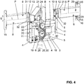
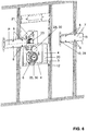
- eine perspektivische Detailansicht eines Gehäuses mit Querträgern für den Einsatz im Tragsystem nach den
Figuren 1 bis 3 ; - Fig. 5
- eine perspektivische Explosionsansicht einer zweiten Ausführungsform eines erfindungsgemässen Tragsystems;
- Fig. 6
- eine weitere perspektivische Explosionsansicht der zweiten Ausführungsform nach
Figur 5 ; und - Fig. 7
- eine perspektivische Ansicht der zweiten Ausführungsform nach der
Figur 5 und6 . - In den
Figuren 1 bis 4 wird eine erste Ausführungsform eines sanitären Tragsystems 1 für einen Sanitärartikel gezeigt. In denFiguren 5 bis 7 wird eine zweite Ausführungsform eines Tragsystems 1 für einen Sanitärartikel gezeigt. Gleiche Teile sind mit gleichen Bezugszeichen versehen und es wird in der Folge auf beide Ausführungsformen Bezug genommen. - Das sanitäre Tragsystem 1 dient gemäss beiden Ausführungsformen zur Lagerung eines Sanitärartikels. Der Sanitärartikel ist vorzugsweise ein Waschtisch. Dabei ist das sanitäre Tragsystem 1 vorzugsweise hinter einer Vorwand in einem Badezimmer montiert.
- Das sanitäre Tragsystem 1 umfasst zwei beabstandet zueinander liegende und feststehend montierbare Stützen 2. Vorzugsweise sind die Stützen Fussstützen, die auf einem Fussboden aufstehen. Es kann sich aber auch um Stützen handeln, die an einer Wand montiert sind. Weiter umfasst das sanitäre Tragsystem 1 ein zwischen den beiden Stützen 2 liegendes Gehäuse 3 mit einem durch Seitenwände 4 begrenzten Innenraum 5. Im Innenraum 5 des Gehäuses 3 ist eine Abflusseinheit 6 angeordnet. Der Innenraum 5 dient also der Aufnahme der Abflusseinheit 6. Die Abflusseinheit 6 wird in fluidischen Kontakt mit dem Sanitärartikel gebracht und dient der Wegführung von Wasser vom Sanitärartikel. Weiter umfasst das sanitäre Tragsystem 1 zwei seitlich und im Wesentlichen quer von den Stützen 2 abragende Querträger 7. Die Querträger 7 weisen jeweils mindestens eine Befestigungsstelle 8 zur Aufnahme von Befestigungselementen zur Befestigung des Sanitärartikels auf. Das heisst, über die Befestigungsstellen 8 kann der Sanitärartikel mit den Querträgern 7 verbunden werden. Die Befestigungsstellen 8 sind vorzugsweise Gewindeöffnungen, in welche dann ein Befestigungselement in der Gestalt einer Gewindestange oder einer Schraube eingreifen kann. In der gezeigten Ausführungsform sind pro Querträger 7 jeweils zwei Befestigungsstellen 8 angeordnet. Es können aber auch vier oder mehr Befestigungsstellen 8 angeordnet werden. Die Befestigungsstellen 8 sind hier bezüglich des Querträgers 7 diagonal versetzt voneinander angeordnet.
- In den
Figuren 2 und3 wird gezeigt, dass das Gehäuse 3 entlang einer Einstellbewegung E in seiner Höhenlage relativ zu den feststehenden Stützen 2 verschiebbar ist. Hierdurch kann das Gehäuse 3 auf verschiedenen Höhenlagen liegen. In derFigur 2 liegt das Gehäuse 3 höher als in derFigur 3 . Die Höhenlage wird im Wesentlichen durch die gewünschte Höhe des Sanitärartikels vorgegeben. Nach erfolgter Einstellbewegung ist das Gehäuse 3 an den feststehenden Stützen 2 festsetzbar. Das heisst, das Gehäuse 3 wird mit den feststehenden Stützen 2 mechanisch fest verbunden, so dass sich das Gehäuse 3 nicht weiter verschieben kann. Gleichermassen sind die Querträger 7 an den Stützen 2 festsetzbar. - Die Querträger 7 stehen in Wirkverbindung mit dem Gehäuse 3. Die Wirkverbindung zwischen Querträger 7 und Gehäuse 3 ist dabei derart, dass bei einer Einstellung der Höhenlage des Gehäuses 3 die Querträger 7 gemeinsam mit dem Gehäuse 3 verschoben werden. Hierdurch wird die relative Lage zwischen dem Querträger 7 und dem Gehäuse 3 mit der Abflusseinheit 6 in jeder Höhenlage gleich sein. Das Gehäuse 3 und die Querträger 7 werden als eine Einheit bei der Einstellung der Höhenlage des Gehäuses 3 entlang der Einstellbewegung E verschoben. Hierdurch bleibt die relative Lage des Gehäuses 3 mit der Abflusseinheit 6 und der Querträger 7 immer gleich, was den Vorteil hat, dass die Anschlussstruktur für den Sanitärartikel auf Seiten des Tragsystems 1 bei jeder Höhenlage gleich ist. Die Anschlussstruktur muss also auf Seiten des Tragsystems 1 nicht angepasst werden.
- In beiden Ausführungsformen ist die Wirkverbindung zwischen dem Querträger 7 und dem Gehäuse 3 eine mechanische Verbindung. Die Wirkverbindung kann unterschiedlich ausgebildet sein. Die mechanische Verbindung bzw. die Wirkverbindung ist mindestens derart ausgebildet, dass eine Relativbewegung zwischen Gehäuse 3 und Querträger 7 mindestens in Richtung der Einstellbewegung E verhindert wird. Das heisst, die Wirkverbindung stellt die Lage zwischen Gehäuse 3 und Querträger 7 in Richtung der Einstellbewegung sicher.
- In der ersten Ausführungsform, welche in der
Figur 4 bzw. denFiguren 1 bis 3 gezeigt wird, ist die Wirkverbindung eine feste mechanische Verbindung, bei der das Gehäuse 3 über ein Anschlussprofil 11 mit den Querträgern 7 verbunden wird. Hierfür sind entsprechende Schrauben 9 vorgesehen. Pro Querträger 7 sind hier zwei Schrauben 9 vorgesehen. Mit den Schrauben 9 werden die Querträger 7 über das Anschlussprofil 11 mit dem Gehäuse 3 entsprechend verbunden. Das Anschlussprofil 11 selbst steht über Befestigungsstellen 12 mit der Stütze 2 in Verbindung. Die Befestigungsstelle 12 ist eine Schraubverbindung. Die Kraft vom Sanitärartikel wird hier über das Anschlussprofil 11 in die Stütze 2 eingeleitet. - In der zweiten Ausführungsform, welche in den
Figuren 5 bis 7 gezeigt wird, ist für die Wirkverbindung eine Steckverbindung 10 vorgesehen. Für die Steckverbindung 10 weist das Gehäuse 3 eine Lasche 27 auf. Demgegenüber weist der Querträger 7 eine Nute 28 auf, in welcher die Lasche 27 eingreift. Über die Verbindung zwischen Nut und Lasche wird die Positionierung bzw. die Wirkverbindung zwischen Gehäuse 3 und Querträger 7 bereitgestellt. Der Querträger 2 steht hier mit einem zusätzlichen Verbindungsmittel 14 mit der Stütze 2 in Verbindung. - Die Wirkverbindung zwischen dem Gehäuse 3 und dem Querträger 7 hat bei beiden Ausführungsformen im Wesentlichen die Funktion, dass die Position zwischen Gehäuse 3 und Querträger 7 festgelegt wird. Es ist nicht zwingend nötig, dass über diese Wirkverbindung auch eine entsprechende Gewichtskraft, die vom Sanitärartikel her in die Stützen einzuleiten ist, übertragen werden kann. Dies wäre aber denkbar.
- In beiden gezeigten Ausführungsformen weist das Gehäuse 3, wie oben im Zusammenhang mit der ersten Ausführungsform bereits erwähnt, zwei seitlich am Gehäuse 3 angeordnete Anschlussprofile 11 auf. Die Anschlussprofile 11 bilden dabei vorzugsweise einen integralen Bestandteil des Gehäuses 3 und erstrecken sich, in Einbaulage gesehen, vom Gehäuse 3 nach oben hin weg. Beispielsweise ist das Anschlussprofil 11 an den Seitenwänden 4 am Gehäuse 3 angeschweisst oder fest verschraubt. Das Anschlussprofil 11 könnte aber auch durch eine dem Stützenteil 2 zugewandte Seitenwand 4 bereitgestellt werden. An den oberen Enden des Anschlussprofils 11 sind dann die Querträger 7 entsprechend befestigt. Das heisst, die Querträger 7 liegen mit einem Abstand zu den wesentlichen Gehäuseteilen. Jedes Anschlussprofil 11 weist Befestigungsstellen 12 zur Befestigung des Gehäuses 3 an den Stützen 2 auf. Darüber hinaus weist jedes der Anschlussprofile 11 Aufnahmeabschnitte 13 auf, welche der Bereitstellung der besagten Wirkverbindung dienen. Die Aufnahmeabschnitte 13 nehmen in der ersten Ausführungsform die Schrauben 9 auf und werden in der zweiten Ausführungsform durch die Lasche 27 bzw. die Nute 28 bereitgestellt. Die Aufnahmeabschnitte 13 liegen am freien Ende der Anschlussprofile 11.
- Im Bereich der Verbindungsstelle zwischen Querträger 7 und Anschlussprofil 11 weist der Querträger 7 einen Absatz 31 auf. Der Absatz 31 und das Anschlussprofil 11 definieren einen Aufnahmeraum 32, in welchem die Stütze 2 liegt.
- Die Querträger 7 weisen den Querschnitt eines sich entlang einer Profilachse P erstreckenden Profils auf. Das Profil ist in der gezeigten Ausführungsform ein Hohlkörperprofil mit einem rechteckigen Querschnitt. Es können aber auch andere Profile eingesetzt werden. Die Ausbildung eines Profils ist dabei vorteilhaft, weil entsprechende Kräfte von dem Sanitärartikel übernommen werden können.
- Die Querträger 7 weisen in beiden gezeigten Ausführungsformen an ihren freien Enden 15 gegenüber der Stützen 2 einen Befestigungsabschnitt 16 auf. Mit dem Befestigungsabschnitt 16 lassen sich die Querträger 7 im Bereich ihrer freien Enden 15 zu einem weiteren Stützenteil 17 montieren. Die Befestigungsabschnitte 16 sind in der Form von Schlitzen ausgebildet, welche in Richtung der Einstellbewegung E orientiert sind. Eine Schraube 29 ragt durch die Schlitze hindurch in ein Gewinde am weiteren Stützenteil 17. In beiden Ausführungsformen ist ein derartiges weiteres Stützenteil 17 vorhanden. Das weitere Stützenteil 17 wird dabei ebenfalls ortsfest in einem Raum befestigt. Die Querträger 7 sind also beidseitig befestigt, einerseits direkt oder indirekt mit der Stütze 2 und andererseits mit dem weiteren Stützenteil 17. Hierdurch kann die Lagerung verbessert werden.
- Das Gehäuse 3 ist rückseitig mit einer Rückwand 18 verschlossen und frontseitig mit einer Zugangsöffnung 19 ausgebildet. Umfangsseitig weist das Gehäuse 3 die Seitenwand 4 auf. Die Zugangsöffnung 19 bildet dabei einen Zugang zum Innenraum 5. Die Zugangsöffnung 19 kann dabei vollständig offen sein oder sie kann mit einer Wartungstüre oder einer Wartungsklappe verschlossen sein. Die Zugangsöffnung 19 ist dabei möglichst gross gewählt, so dass ein einfacher Zugang zur Abflusseinheit 6 geschaffen werden kann. Durch diesen Zugang können entsprechende Wartungsarbeiten ausgeführt werden.
- Das Gehäuse 3 weist in der gezeigten Ausführungsform einen unteren Gehäuseabschnitt 20 und einen oberen Gehäuseabschnitt 21 auf. Der untere Gehäuseabschnitt 20 ist dabei bezüglich seines Volumens grösser ausgebildet als der obere Gehäuseabschnitt 21. Es ist aber auch denkbar, dass nur ein einziger Gehäuseabschnitt vorhanden ist. Die beiden Gehäuseabschnitte 20, 21 sind miteinander verbunden, insbesondere ragt die Abflusseinheit 6 vom oberen Gehäuseabschnitt 21 in den unteren Gehäuseabschnitt 20. Bezüglich seiner Breite ist der untere Gehäuseabschnitt 20, quer zu den Stützen 2 gesehen, breiter ausgebildet als der obere Gehäuseabschnitt 21. Die Breite ist mit dem Bezugszeigen B eingezeichnet. Die beiden Querträger 7 sind in Einbaulage derart angeordnet, dass diese oberhalb des unteren Gehäuseabschnittes 20 liegen. Die Querträger liegen im Wesentlichen auf der Höhe des oberen Gehäuseabschnittes 21. Je nach Form des zu montierenden Sanitärartikels werden von vorne her gesehen im Wesentlichen die Querträger 7 und der obere Gehäuseabschnitt 21 vom Sanitärartikel überdeckt, nicht aber der untere Gehäuseabschnitt 20. Hierdurch kann sichergestellt werden, dass Zugang zum unteren Gehäuseabschnitt 21 geschaffen werden kann.
- Die Stützen 2 weisen vorzugsweise in Richtung der Mittelachse M der Stützen 2 verlaufende Nuten 22 auf. In diesen Nuten 22 ist das Gehäuse 3 verschieblich gelagert.
- Die Abflusseinheit 6 weist in der gezeigten Ausführungsform einen Einlassstutzen 23, ein Sperrventil 24, ein Siphon 25 und einen Auslassstutzen 26 auf. Der Einlassstutzen 23 ragt durch die Zugangsöffnung 19 aus dem Innenraum 5 des Gehäuses aus dem Gehäuse 3 heraus. Mit dem Einlassstutzen 23 kann der Abfluss des Sanitärartikels verbunden werden. Der Einlassstutzen 23 ragt dabei im Wesentlichen rechtwinklig oder mit einem kleinen Winkel winklig geneigt zu den Stützen 2 nach vorne hin. Das heisst, dass der Sanitärartikel ebenfalls von vorne in einer entsprechenden rechtwinklig oder in einem kleinen Winkel orientierten Bewegung zu den Stützen 2 montiert werden kann. Der Auslassstutzen 26 ragt hier durch eine der genannten Seitenwände 4 aus dem Innenraum 5 des Gehäuses 3 aus dem Gehäuse 3 heraus und wird mit einem Abwassernetz verbunden. Das Sperrventil 24 und der Siphon 25 weisen eine mit einem Deckel 30 verschlossene Zugangsöffnung auf. Über diese Zugangsöffnung kann Zugang zum Inneren der Abflusseinheit 6 geschaffen werden. Dies beispielsweise bei verstopftem Siphon 25 oder bei undichtem Sperrventil 24. Die Zugangsöffnungen mit den Deckeln 30 sind hier derart angeordnet, dass diese allesamt im unteren Gehäuseabschnitt 20 liegen, welcher idealerweise nicht vom Sanitärartikel überdeckt wird.
- Bei beiden Ausführungsformen ist oberhalb des Gehäuses 2 eine optionale Armaturenplatte 34 angeordnet. Die Armaturenplatte 34 umfasst mindestens eine Anschlussstelle 37 für eine Auslaufarmatur, welche Anschlussstelle 37 über mindestens eine Wasserleitung mit Wasser versorgt wird. Die Wasserleitung kann ebenfalls in das Gehäuse 2 einragen und kann im Gehäuse 2 an die Wasserversorgung angeschlossen werden.
- Weiter sind die beiden Stützen 2 über einen zusätzlichen Querträger 36 miteinander verbunden. Der Querträger 36 ist hier am freien oberen Ende der Stützen 2 angeordnet. Hierdurch wird die Stabilität des Tragsystems weiter erhöht. Auch sind die beiden zusätzlichen Stützenteil 17 mit einem optionalen Querträger 36 miteinander verbunden.
BEZUGSZEICHENLISTE 1 Tragsystem 24 Sperrventil 2 Stützen 25 Siphon 3 Gehäuse 26 Auslassstutzen 4 Seitenwände 27 Lasche 5 Innenraum 28 Nute 6 Abflusseinheit 29 Schraube 7 Querträger 30 Deckel 8 Befestigungsstelle 31 Absatz 9 Schraube 32 Aufnahmeraum 10 Steckverbindung 34 Armaturenplatte 11 Anschlussprofil 36 Querträger 12 Befestigungsstellen 37 Anschlussstelle 13 Aufnahmeabschnitte 14 zusätzliches Verbindungsmittel B Breite 15 freie Enden 16 Befestigungsabschnitt M Mittelachse 17 weiteres Stützenteil E Einstellbewegung 18 Rückwand P Profilachse 19 Zugangsöffnung 20 unterer Gehäuseabschnitt 21 oberer Gehäuseabschnitt 22 Nut 23 Einlassstutzen
Claims (17)
- Sanitäres Tragsystem (1) für einen Sanitärartikel, insbesondere einen Waschtisch, umfassend
zwei beabstandet zueinander liegende und feststehend montierbare Stützen (2),
ein zwischen den beiden Stützen (2) liegendes Gehäuse (3) mit einem durch Seitenwände (4) begrenzten Innenraum (5),
eine Abflusseinheit (6), welche fest im besagten Innenraum (5) anordbar bzw. angeordnet ist, und
zwei Querträger (7) mit jeweils mindestens einer Befestigungsstelle (8) zur Aufnahme von Befestigungselementen zur Befestigung des Sanitärartikels an den beiden Querträgern (7), wobei jeder der Querträger (7) in fester Verbindung mit jeweils einer der Stützen (2) steht und quer von der jeweiligen Stütze (2) auf der dem Gehäuse (3) gegenüberliegenden Seite von der Stütze (2) abragt. - Sanitäres Tragsystem (1) nach Anspruch 1, dadurch gekennzeichnet, dass das Gehäuse (3) entlang einer Einstellbewegung (E) in seiner Höhenlage relativ zu den feststehenden Stützen (2) verschiebbar ist und nach erfolgter Verschiebung an den feststehenden Stützen (2) festsetzbar ist, und
dass die Querträger (7) mit dem Gehäuse (3) derart in Wirkverbindung stehen, dass bei einer Einstellung der Höhenlage des Gehäuses (3) relativ zu den feststehenden Stützen (2) die Querträger (7) gemeinsam mit dem Gehäuse (3) verschoben werden, so dass die relative Lage zwischen den Querträgern (7) und dem Gehäuse (3) mit der Abflusseinheit (6) in jeder Höhenlage gleich ist. - Sanitäres Tragsystem (1) nach Anspruch 2, dadurch gekennzeichnet, dass die Wirkverbindung eine mechanische Verbindung ist, welche eine Relativbewegung zwischen Gehäuse (3) und Querträger (7) mindestens in Richtung der Einstellbewegung (E) verhindert.
- Sanitäres Tragsystem (1) nach einem der vorhergehenden Ansprüche 2 bis 3, dadurch gekennzeichnet, dass das Gehäuse (3) beidseitig, insbesondere auf der den Stützen (2) zugewandter Seite, je ein Anschlussprofil (11) aufweist, welches Befestigungsstellen (12) zur Befestigung des Gehäuses (3) an den Stützen (2) aufweist, und welches Aufnahmeabschnitte (13) zur Bereitstellung der besagten Wirkverbindung zwischen den Querträgern (7) und dem Gehäuse (3) aufweist.
- Sanitäres Tragsystem (1) nach Anspruch 4, dadurch gekennzeichnet, dass die Wirkverbindung zwischen den Querträgern (7) und den Anschlussprofilen (11) des Gehäuses (3) derart ausgebildet ist, dass zugleich die Last des zu befestigenden Sanitärartikels von den Querträgern (7) über die Verbindung zwischen Querträger (7) und Anschlussprofil (11) sowie über die Verbindung zwischen Anschlussprofil (11) und den Stützen (2) in die Stützen (2) eingeleitet wird.
- Sanitäres Tragsystem nach Anspruch 4, dadurch gekennzeichnet, dass die Wirkverbindung zwischen dem Anschlussprofil (11) und dem Querträger (7) lediglich die Verbindung zwischen Gehäuse (3) und Querträger (7) bereitstellt; und dass mindestens ein zusätzliches Verbindungselement (14) vorgesehen ist, mit welchem der Querträger (7) zur Stütze (2) befestigt wird.
- Sanitäres Tragsystem nach einem der vorhergehenden Ansprüche 2 bis 6, dadurch gekennzeichnet, dass die Wirkverbindung durch mindestens eine Steckverbindung (10) zwischen Gehäuse (3) und Querträger (7) bereitgestellt wird; und/oder dass die Wirkverbindung vorzugsweise durch mindestens eine Schraube (9) zwischen Gehäuse (3) und Querträger (7) bereitgestellt wird.
- Sanitäres Tragsystem (1) nach einem der vorhergehenden Ansprüche, dadurch gekennzeichnet, dass die Querträger (7) den Querschnitt eines sich entlang einer Profilachse (P) erstreckenden Profils aufweisen, wobei die Profilachse (P) vorzugsweise rechtwinklig zu den Stützen (2) orientiert ist; und/oder wobei das Profil vorzugsweise ein U-Profil oder ein Hohlkörperprofil mit rechteckigem Querschnitt ist.
- Sanitäres Tragsystem (1) nach einem der vorhergehenden Ansprüche, dadurch gekennzeichnet, dass die Querträger (7) an ihren freien Enden (15) gegenüber der Stützen (2) einen Befestigungsabschnitt (16) aufweisen, und dass das Tragsystem (1) zwei weitere ortsfeste Stützenteile (17) umfasst, wobei die Querträger mit dem Befestigungsabschnitt (16) zum weiteren ortsfesten Stützenteil (17) montierbar sind.
- Sanitäres Tragsystem (1) nach einem der vorhergehenden Ansprüche, dadurch gekennzeichnet, dass das Gehäuse (3) umfangsseitig mit den Seitenwänden (4) sowie rückseitig mit einer Rückwand (18) verschlossen ist und frontseitig mit einer Zugangsöffnung (19) offen ausgebildet ist, wobei der Innenraum (5) durch die Zugangsöffnung (19) zugänglich ist.
- Sanitäres Tragsystem (1) nach einem der vorhergehenden Ansprüche, dadurch gekennzeichnet, dass das Gehäuse (3) einen unteren Gehäuseabschnitt (20) und einen oberen Gehäuseabschnitt (21) aufweist, wobei die beiden Gehäuseabschnitte (20, 21) miteinander verbunden sind, und wobei der untere Gehäuseabschnitt (20) bezüglich seiner Breite (B) quer zu den Stützen (2) gesehen breiter ausgebildet ist als der obere Gehäuseabschnitt (21).
- Sanitäres Tragsystem (1) nach Anspruch 11, dadurch gekennzeichnet, dass die Querträger (7) in Einbaulage oberhalb des unteren Gehäuseabschnittes (20) liegen.
- Sanitäres Tragsystem (1) nach einem der vorhergehenden Ansprüche, dadurch gekennzeichnet, dass die Stützen (2) in Richtung der Mittelachse (M) der Stützen (2) verlaufende Nut (22) aufweisen, in welcher das Gehäuse (3) verschiebbar gelagert ist.
- Sanitäres Tragsystem (1) nach einem der vorhergehenden Ansprüche, dadurch gekennzeichnet, dass das Tragsystem (1) weiter eine Armaturenplatte (34) mit mindestens einer Anschlussstelle (37) für eine Auslaufarmatur umfasst, welche Anschlussstelle (37) über mindestens eine Wasserleitung mit Wasser versorgt wird, wobei die Wasserleitung vorzugsweise in das Gehäuse (2) einragt und im Gehäuse (2) an die Wasserversorgung anschliessbar ist.
- Sanitäres Anschlusssystem für einen Sanitärartikel, insbesondere einen Waschtisch, umfassend ein sanitäres Tragsystem (1) nach einem der vorhergehenden Ansprüche, eine Abflusseinheit (6), welche im Innenraum (5) des besagten Gehäuses angeordnet ist sowie einen Sanitärartikel, insbesondere einen Waschtisch, welcher Sanitärartikel in fluidischer Verbindung mit der Abflusseinheit (6) und in mechanischer Verbindung mit den Querträgern (7) steht.
- Sanitäres Anschlusssystem nach Anspruch 15, dadurch gekennzeichnet, dass die Abflusseinheit (6) einen Einlassstutzen (23), ein Sperrventil (24), ein Siphon (25) und einen Auslassstutzen (26) aufweist, wobei der Einlassstutzen (23) durch die Zugangsöffnung (19) aus dem Innenraum (5) des Gehäuses (3) aus dem Gehäuse (3) herausragt, und wobei der Auslassstutzen (26) vorzugsweise durch eine der genannten Seitenwände (4) aus dem Innenraum (5) des Gehäuses (3) aus dem Gehäuse (3) herausragt.
- Sanitäres Anschlusssystem nach Anspruch 16, dadurch gekennzeichnet, dass der Siphon (25) und das Sperrventil (24) je eine mit einem Deckel (30) verschlossene Zugangsöffnung aufweist, welche Zugangsöffnungen allesamt unterhalb des Waschtisches liegen.
Priority Applications (8)
| Application Number | Priority Date | Filing Date | Title |
|---|---|---|---|
| PL18172684T PL3569777T3 (pl) | 2018-05-16 | 2018-05-16 | Sanitarny układ nośny |
| EP18172684.5A EP3569777B1 (de) | 2018-05-16 | 2018-05-16 | Sanitäres tragsystem |
| DK18172684.5T DK3569777T3 (da) | 2018-05-16 | 2018-05-16 | Sanitært støttesystem |
| PCT/EP2019/057884 WO2019185810A1 (de) | 2018-03-29 | 2019-03-28 | Ablaufanordnung für einen waschtisch |
| CN201980023149.2A CN111936708B (zh) | 2018-03-29 | 2019-03-28 | 用于盥洗台的排放装置 |
| EP19714201.1A EP3775415B1 (de) | 2018-03-29 | 2019-03-28 | Ablaufanordnung für einen waschtisch |
| US17/042,597 US11486118B2 (en) | 2018-03-29 | 2019-03-28 | Drain arrangement for a washstand |
| AU2019240836A AU2019240836B2 (en) | 2018-03-29 | 2019-03-28 | Drain arrangement for a washstand |
Applications Claiming Priority (1)
| Application Number | Priority Date | Filing Date | Title |
|---|---|---|---|
| EP18172684.5A EP3569777B1 (de) | 2018-05-16 | 2018-05-16 | Sanitäres tragsystem |
Publications (2)
| Publication Number | Publication Date |
|---|---|
| EP3569777A1 true EP3569777A1 (de) | 2019-11-20 |
| EP3569777B1 EP3569777B1 (de) | 2020-08-12 |
Family
ID=62196370
Family Applications (1)
| Application Number | Title | Priority Date | Filing Date |
|---|---|---|---|
| EP18172684.5A Active EP3569777B1 (de) | 2018-03-29 | 2018-05-16 | Sanitäres tragsystem |
Country Status (3)
| Country | Link |
|---|---|
| EP (1) | EP3569777B1 (de) |
| DK (1) | DK3569777T3 (de) |
| PL (1) | PL3569777T3 (de) |
Cited By (1)
| Publication number | Priority date | Publication date | Assignee | Title |
|---|---|---|---|---|
| CN115126053A (zh) * | 2021-03-24 | 2022-09-30 | 吉博力国际股份公司 | 盥洗台装置 |
Citations (6)
| Publication number | Priority date | Publication date | Assignee | Title |
|---|---|---|---|---|
| DE3800840C1 (de) * | 1988-01-14 | 1989-03-30 | Mero-Werke Dr.-Ing. Max Mengeringhausen Gmbh & Co, 8700 Wuerzburg, De | |
| EP0408500A2 (de) | 1989-07-13 | 1991-01-16 | Geberit AG | Anordnung für die Vorwandmontage eines Waschtisches oder eines ähnlichen Sanitärartikels |
| EP0978597A2 (de) * | 1998-08-07 | 2000-02-09 | Friatec Aktiengesellschaft | Vorrichtung zur Befestigung eines Bauelements |
| EP1936045A1 (de) | 2006-12-19 | 2008-06-25 | Geberit Technik Ag | Installationsvorrrichtung für eine sanitäre Einrichtung und sanitäre Einrichtung mit einer solchen Installationsvorrichtung |
| EP1963045A1 (de) | 2005-12-15 | 2008-09-03 | Trumpf Werkzeugmaschinen GmbH + Co. KG | Verfahren zur zustandserkennung eines optischen elements |
| FR2942817A1 (fr) * | 2009-03-04 | 2010-09-10 | Siamp Cedap Reunies | Cuvette de toilette reglable en hauteur |
-
2018
- 2018-05-16 PL PL18172684T patent/PL3569777T3/pl unknown
- 2018-05-16 DK DK18172684.5T patent/DK3569777T3/da active
- 2018-05-16 EP EP18172684.5A patent/EP3569777B1/de active Active
Patent Citations (6)
| Publication number | Priority date | Publication date | Assignee | Title |
|---|---|---|---|---|
| DE3800840C1 (de) * | 1988-01-14 | 1989-03-30 | Mero-Werke Dr.-Ing. Max Mengeringhausen Gmbh & Co, 8700 Wuerzburg, De | |
| EP0408500A2 (de) | 1989-07-13 | 1991-01-16 | Geberit AG | Anordnung für die Vorwandmontage eines Waschtisches oder eines ähnlichen Sanitärartikels |
| EP0978597A2 (de) * | 1998-08-07 | 2000-02-09 | Friatec Aktiengesellschaft | Vorrichtung zur Befestigung eines Bauelements |
| EP1963045A1 (de) | 2005-12-15 | 2008-09-03 | Trumpf Werkzeugmaschinen GmbH + Co. KG | Verfahren zur zustandserkennung eines optischen elements |
| EP1936045A1 (de) | 2006-12-19 | 2008-06-25 | Geberit Technik Ag | Installationsvorrrichtung für eine sanitäre Einrichtung und sanitäre Einrichtung mit einer solchen Installationsvorrichtung |
| FR2942817A1 (fr) * | 2009-03-04 | 2010-09-10 | Siamp Cedap Reunies | Cuvette de toilette reglable en hauteur |
Cited By (1)
| Publication number | Priority date | Publication date | Assignee | Title |
|---|---|---|---|---|
| CN115126053A (zh) * | 2021-03-24 | 2022-09-30 | 吉博力国际股份公司 | 盥洗台装置 |
Also Published As
| Publication number | Publication date |
|---|---|
| PL3569777T3 (pl) | 2021-03-08 |
| DK3569777T3 (da) | 2020-11-16 |
| EP3569777B1 (de) | 2020-08-12 |
Similar Documents
| Publication | Publication Date | Title |
|---|---|---|
| EP3746609B1 (de) | Anschlussvorrichtung für eine toilettenschüssel | |
| EP3394353B1 (de) | Schlauchführungsvorrichtung und sanitäre auszugsschlauch-armatur | |
| EP2662502B1 (de) | Montagevorrichtung für die Befestigung eines Sanitärapparates | |
| DE102013105544A1 (de) | Wasserablaufvorrichtung für eine sanitäre Anlage, wie einen bodenebenen Duschplatz | |
| EP2876222B1 (de) | Einheit umfassend eine Befestigungsvorrichtung für ein hängendes WC und ein Halteelement. | |
| DE69919801T2 (de) | Stabilisatorstab für Senkgrube | |
| EP3569102B1 (de) | Befestigungssystem für einen waschtisch | |
| EP0386559B1 (de) | Duschabtrennung | |
| EP3149251B1 (de) | Montagevorrichtung | |
| EP3569777B1 (de) | Sanitäres tragsystem | |
| DE102022131506A1 (de) | Mobiles Hochwasserschutzsystem | |
| DE10204683B4 (de) | Becken | |
| EP0733750B1 (de) | Befestigungsvorrichtung eines Spülkastens | |
| EP3647504B1 (de) | Sanitärartikelanordnung | |
| DE102006052247B4 (de) | Wandeinbau-Spülkasten | |
| EP4063576B1 (de) | Waschtischanordnung | |
| DE3707965C2 (de) | ||
| EP2818601A1 (de) | Einstellbarer Einlauf eines Bodenablaufes | |
| EP3918952B1 (de) | Einbaugehäuse | |
| DE202022106082U1 (de) | Montagevorrichtung | |
| DE202010008840U1 (de) | Duschrinnenanordnung mit Klappenbefestigung | |
| EP3569103B1 (de) | Anordnung umfassend ein befestigungssystem für einen unterschrank | |
| EP4592464A2 (de) | Montagevorrichtung | |
| EP3763891A1 (de) | Bidetanordnung | |
| EP4063574A1 (de) | Waschtischanordnung |
Legal Events
| Date | Code | Title | Description |
|---|---|---|---|
| PUAI | Public reference made under article 153(3) epc to a published international application that has entered the european phase |
Free format text: ORIGINAL CODE: 0009012 |
|
| STAA | Information on the status of an ep patent application or granted ep patent |
Free format text: STATUS: THE APPLICATION HAS BEEN PUBLISHED |
|
| AK | Designated contracting states |
Kind code of ref document: A1 Designated state(s): AL AT BE BG CH CY CZ DE DK EE ES FI FR GB GR HR HU IE IS IT LI LT LU LV MC MK MT NL NO PL PT RO RS SE SI SK SM TR |
|
| AX | Request for extension of the european patent |
Extension state: BA ME |
|
| STAA | Information on the status of an ep patent application or granted ep patent |
Free format text: STATUS: REQUEST FOR EXAMINATION WAS MADE |
|
| 17P | Request for examination filed |
Effective date: 20191206 |
|
| RBV | Designated contracting states (corrected) |
Designated state(s): AL AT BE BG CH CY CZ DE DK EE ES FI FR GB GR HR HU IE IS IT LI LT LU LV MC MK MT NL NO PL PT RO RS SE SI SK SM TR |
|
| RIC1 | Information provided on ipc code assigned before grant |
Ipc: E03C 1/324 20060101AFI20200211BHEP |
|
| GRAP | Despatch of communication of intention to grant a patent |
Free format text: ORIGINAL CODE: EPIDOSNIGR1 |
|
| STAA | Information on the status of an ep patent application or granted ep patent |
Free format text: STATUS: GRANT OF PATENT IS INTENDED |
|
| INTG | Intention to grant announced |
Effective date: 20200323 |
|
| GRAS | Grant fee paid |
Free format text: ORIGINAL CODE: EPIDOSNIGR3 |
|
| GRAA | (expected) grant |
Free format text: ORIGINAL CODE: 0009210 |
|
| STAA | Information on the status of an ep patent application or granted ep patent |
Free format text: STATUS: THE PATENT HAS BEEN GRANTED |
|
| AK | Designated contracting states |
Kind code of ref document: B1 Designated state(s): AL AT BE BG CH CY CZ DE DK EE ES FI FR GB GR HR HU IE IS IT LI LT LU LV MC MK MT NL NO PL PT RO RS SE SI SK SM TR |
|
| REG | Reference to a national code |
Ref country code: CH Ref legal event code: EP |
|
| REG | Reference to a national code |
Ref country code: IE Ref legal event code: FG4D Free format text: LANGUAGE OF EP DOCUMENT: GERMAN |
|
| REG | Reference to a national code |
Ref country code: DE Ref legal event code: R096 Ref document number: 502018002150 Country of ref document: DE |
|
| REG | Reference to a national code |
Ref country code: AT Ref legal event code: REF Ref document number: 1301674 Country of ref document: AT Kind code of ref document: T Effective date: 20200915 Ref country code: CH Ref legal event code: NV Representative=s name: ISLER AND PEDRAZZINI AG, CH |
|
| REG | Reference to a national code |
Ref country code: SE Ref legal event code: TRGR |
|
| REG | Reference to a national code |
Ref country code: DK Ref legal event code: T3 Effective date: 20201110 |
|
| REG | Reference to a national code |
Ref country code: NL Ref legal event code: FP |
|
| REG | Reference to a national code |
Ref country code: NO Ref legal event code: T2 Effective date: 20200812 |
|
| REG | Reference to a national code |
Ref country code: LT Ref legal event code: MG4D |
|
| PG25 | Lapsed in a contracting state [announced via postgrant information from national office to epo] |
Ref country code: GR Free format text: LAPSE BECAUSE OF FAILURE TO SUBMIT A TRANSLATION OF THE DESCRIPTION OR TO PAY THE FEE WITHIN THE PRESCRIBED TIME-LIMIT Effective date: 20201113 Ref country code: BG Free format text: LAPSE BECAUSE OF FAILURE TO SUBMIT A TRANSLATION OF THE DESCRIPTION OR TO PAY THE FEE WITHIN THE PRESCRIBED TIME-LIMIT Effective date: 20201112 Ref country code: FI Free format text: LAPSE BECAUSE OF FAILURE TO SUBMIT A TRANSLATION OF THE DESCRIPTION OR TO PAY THE FEE WITHIN THE PRESCRIBED TIME-LIMIT Effective date: 20200812 Ref country code: LT Free format text: LAPSE BECAUSE OF FAILURE TO SUBMIT A TRANSLATION OF THE DESCRIPTION OR TO PAY THE FEE WITHIN THE PRESCRIBED TIME-LIMIT Effective date: 20200812 Ref country code: HR Free format text: LAPSE BECAUSE OF FAILURE TO SUBMIT A TRANSLATION OF THE DESCRIPTION OR TO PAY THE FEE WITHIN THE PRESCRIBED TIME-LIMIT Effective date: 20200812 |
|
| PG25 | Lapsed in a contracting state [announced via postgrant information from national office to epo] |
Ref country code: LV Free format text: LAPSE BECAUSE OF FAILURE TO SUBMIT A TRANSLATION OF THE DESCRIPTION OR TO PAY THE FEE WITHIN THE PRESCRIBED TIME-LIMIT Effective date: 20200812 Ref country code: RS Free format text: LAPSE BECAUSE OF FAILURE TO SUBMIT A TRANSLATION OF THE DESCRIPTION OR TO PAY THE FEE WITHIN THE PRESCRIBED TIME-LIMIT Effective date: 20200812 Ref country code: IS Free format text: LAPSE BECAUSE OF FAILURE TO SUBMIT A TRANSLATION OF THE DESCRIPTION OR TO PAY THE FEE WITHIN THE PRESCRIBED TIME-LIMIT Effective date: 20201212 |
|
| PG25 | Lapsed in a contracting state [announced via postgrant information from national office to epo] |
Ref country code: SM Free format text: LAPSE BECAUSE OF FAILURE TO SUBMIT A TRANSLATION OF THE DESCRIPTION OR TO PAY THE FEE WITHIN THE PRESCRIBED TIME-LIMIT Effective date: 20200812 Ref country code: EE Free format text: LAPSE BECAUSE OF FAILURE TO SUBMIT A TRANSLATION OF THE DESCRIPTION OR TO PAY THE FEE WITHIN THE PRESCRIBED TIME-LIMIT Effective date: 20200812 Ref country code: RO Free format text: LAPSE BECAUSE OF FAILURE TO SUBMIT A TRANSLATION OF THE DESCRIPTION OR TO PAY THE FEE WITHIN THE PRESCRIBED TIME-LIMIT Effective date: 20200812 Ref country code: CZ Free format text: LAPSE BECAUSE OF FAILURE TO SUBMIT A TRANSLATION OF THE DESCRIPTION OR TO PAY THE FEE WITHIN THE PRESCRIBED TIME-LIMIT Effective date: 20200812 |
|
| REG | Reference to a national code |
Ref country code: DE Ref legal event code: R097 Ref document number: 502018002150 Country of ref document: DE |
|
| PG25 | Lapsed in a contracting state [announced via postgrant information from national office to epo] |
Ref country code: AL Free format text: LAPSE BECAUSE OF FAILURE TO SUBMIT A TRANSLATION OF THE DESCRIPTION OR TO PAY THE FEE WITHIN THE PRESCRIBED TIME-LIMIT Effective date: 20200812 Ref country code: ES Free format text: LAPSE BECAUSE OF FAILURE TO SUBMIT A TRANSLATION OF THE DESCRIPTION OR TO PAY THE FEE WITHIN THE PRESCRIBED TIME-LIMIT Effective date: 20200812 |
|
| PLBE | No opposition filed within time limit |
Free format text: ORIGINAL CODE: 0009261 |
|
| STAA | Information on the status of an ep patent application or granted ep patent |
Free format text: STATUS: NO OPPOSITION FILED WITHIN TIME LIMIT |
|
| PG25 | Lapsed in a contracting state [announced via postgrant information from national office to epo] |
Ref country code: SK Free format text: LAPSE BECAUSE OF FAILURE TO SUBMIT A TRANSLATION OF THE DESCRIPTION OR TO PAY THE FEE WITHIN THE PRESCRIBED TIME-LIMIT Effective date: 20200812 |
|
| 26N | No opposition filed |
Effective date: 20210514 |
|
| PG25 | Lapsed in a contracting state [announced via postgrant information from national office to epo] |
Ref country code: MC Free format text: LAPSE BECAUSE OF FAILURE TO SUBMIT A TRANSLATION OF THE DESCRIPTION OR TO PAY THE FEE WITHIN THE PRESCRIBED TIME-LIMIT Effective date: 20200812 Ref country code: LU Free format text: LAPSE BECAUSE OF NON-PAYMENT OF DUE FEES Effective date: 20210516 |
|
| PG25 | Lapsed in a contracting state [announced via postgrant information from national office to epo] |
Ref country code: IE Free format text: LAPSE BECAUSE OF NON-PAYMENT OF DUE FEES Effective date: 20210516 |
|
| PG25 | Lapsed in a contracting state [announced via postgrant information from national office to epo] |
Ref country code: PT Free format text: LAPSE BECAUSE OF FAILURE TO SUBMIT A TRANSLATION OF THE DESCRIPTION OR TO PAY THE FEE WITHIN THE PRESCRIBED TIME-LIMIT Effective date: 20201214 |
|
| P01 | Opt-out of the competence of the unified patent court (upc) registered |
Effective date: 20230516 |
|
| PG25 | Lapsed in a contracting state [announced via postgrant information from national office to epo] |
Ref country code: CY Free format text: LAPSE BECAUSE OF FAILURE TO SUBMIT A TRANSLATION OF THE DESCRIPTION OR TO PAY THE FEE WITHIN THE PRESCRIBED TIME-LIMIT Effective date: 20200812 |
|
| PG25 | Lapsed in a contracting state [announced via postgrant information from national office to epo] |
Ref country code: HU Free format text: LAPSE BECAUSE OF FAILURE TO SUBMIT A TRANSLATION OF THE DESCRIPTION OR TO PAY THE FEE WITHIN THE PRESCRIBED TIME-LIMIT; INVALID AB INITIO Effective date: 20180516 |
|
| PG25 | Lapsed in a contracting state [announced via postgrant information from national office to epo] |
Ref country code: SI Free format text: LAPSE BECAUSE OF FAILURE TO SUBMIT A TRANSLATION OF THE DESCRIPTION OR TO PAY THE FEE WITHIN THE PRESCRIBED TIME-LIMIT Effective date: 20200812 |
|
| PG25 | Lapsed in a contracting state [announced via postgrant information from national office to epo] |
Ref country code: MK Free format text: LAPSE BECAUSE OF FAILURE TO SUBMIT A TRANSLATION OF THE DESCRIPTION OR TO PAY THE FEE WITHIN THE PRESCRIBED TIME-LIMIT Effective date: 20200812 |
|
| REG | Reference to a national code |
Ref country code: NL Ref legal event code: PD Owner name: GEBERIT HOLDING AG; CH Free format text: DETAILS ASSIGNMENT: CHANGE OF OWNER(S), MERGE; FORMER OWNER NAME: GEBERIT INTERNATIONAL AG Effective date: 20240604 Ref country code: NL Ref legal event code: HC Owner name: GEBERIT INTERNATIONAL AG; CH Free format text: DETAILS ASSIGNMENT: CHANGE OF OWNER(S), CHANGE OF OWNER(S) NAME; FORMER OWNER NAME: GEBERIT HOLDING AG Effective date: 20240604 |
|
| PGFP | Annual fee paid to national office [announced via postgrant information from national office to epo] |
Ref country code: NL Payment date: 20240521 Year of fee payment: 7 |
|
| PGFP | Annual fee paid to national office [announced via postgrant information from national office to epo] |
Ref country code: GB Payment date: 20240521 Year of fee payment: 7 |
|
| PGFP | Annual fee paid to national office [announced via postgrant information from national office to epo] |
Ref country code: DK Payment date: 20240527 Year of fee payment: 7 |
|
| PGFP | Annual fee paid to national office [announced via postgrant information from national office to epo] |
Ref country code: NO Payment date: 20240528 Year of fee payment: 7 Ref country code: FR Payment date: 20240528 Year of fee payment: 7 |
|
| PGFP | Annual fee paid to national office [announced via postgrant information from national office to epo] |
Ref country code: PL Payment date: 20240424 Year of fee payment: 7 |
|
| REG | Reference to a national code |
Ref country code: BE Ref legal event code: PD Owner name: GEBERIT HOLDING AG; CH Free format text: DETAILS ASSIGNMENT: CHANGE OF OWNER(S), MERGE; FORMER OWNER NAME: GEBERIT INTERNATIONAL AG Effective date: 20240528 Ref country code: BE Ref legal event code: HC Owner name: GEBERIT INTERNATIONAL AG; CH Free format text: DETAILS ASSIGNMENT: CHANGE OF OWNER(S), CHANGE OF OWNER(S) NAME; FORMER OWNER NAME: GEBERIT HOLDING AG Effective date: 20240528 |
|
| PGFP | Annual fee paid to national office [announced via postgrant information from national office to epo] |
Ref country code: SE Payment date: 20240521 Year of fee payment: 7 Ref country code: BE Payment date: 20240521 Year of fee payment: 7 |
|
| PG25 | Lapsed in a contracting state [announced via postgrant information from national office to epo] |
Ref country code: MT Free format text: LAPSE BECAUSE OF FAILURE TO SUBMIT A TRANSLATION OF THE DESCRIPTION OR TO PAY THE FEE WITHIN THE PRESCRIBED TIME-LIMIT Effective date: 20200812 |
|
| PGFP | Annual fee paid to national office [announced via postgrant information from national office to epo] |
Ref country code: IT Payment date: 20240522 Year of fee payment: 7 |
|
| REG | Reference to a national code |
Ref country code: AT Ref legal event code: PC Ref document number: 1301674 Country of ref document: AT Kind code of ref document: T Owner name: GEBERIT INTERNATIONAL AG, CH Effective date: 20241118 |
|
| PGFP | Annual fee paid to national office [announced via postgrant information from national office to epo] |
Ref country code: DE Payment date: 20250521 Year of fee payment: 8 |
|
| PGFP | Annual fee paid to national office [announced via postgrant information from national office to epo] |
Ref country code: CH Payment date: 20250601 Year of fee payment: 8 |
|
| PGFP | Annual fee paid to national office [announced via postgrant information from national office to epo] |
Ref country code: AT Payment date: 20250522 Year of fee payment: 8 |
|
| PG25 | Lapsed in a contracting state [announced via postgrant information from national office to epo] |
Ref country code: TR Free format text: LAPSE BECAUSE OF FAILURE TO SUBMIT A TRANSLATION OF THE DESCRIPTION OR TO PAY THE FEE WITHIN THE PRESCRIBED TIME-LIMIT Effective date: 20200812 |
|
| REG | Reference to a national code |
Ref country code: DK Ref legal event code: EBP Effective date: 20250531 |
|
| REG | Reference to a national code |
Ref country code: NL Ref legal event code: MM Effective date: 20250601 |
|
| PG25 | Lapsed in a contracting state [announced via postgrant information from national office to epo] |
Ref country code: NO Free format text: LAPSE BECAUSE OF NON-PAYMENT OF DUE FEES Effective date: 20250531 |
|
| PG25 | Lapsed in a contracting state [announced via postgrant information from national office to epo] |
Ref country code: SE Free format text: LAPSE BECAUSE OF NON-PAYMENT OF DUE FEES Effective date: 20250517 |
|
| REG | Reference to a national code |
Ref country code: SE Ref legal event code: EUG |
|
| GBPC | Gb: european patent ceased through non-payment of renewal fee |
Effective date: 20250516 |
|
| REG | Reference to a national code |
Ref country code: BE Ref legal event code: MM Effective date: 20250531 |
|
| PG25 | Lapsed in a contracting state [announced via postgrant information from national office to epo] |
Ref country code: NL Free format text: LAPSE BECAUSE OF NON-PAYMENT OF DUE FEES Effective date: 20250601 |
|
| PG25 | Lapsed in a contracting state [announced via postgrant information from national office to epo] |
Ref country code: GB Free format text: LAPSE BECAUSE OF NON-PAYMENT OF DUE FEES Effective date: 20250516 |
|
| PG25 | Lapsed in a contracting state [announced via postgrant information from national office to epo] |
Ref country code: DK Free format text: LAPSE BECAUSE OF NON-PAYMENT OF DUE FEES Effective date: 20250531 |
|
| PG25 | Lapsed in a contracting state [announced via postgrant information from national office to epo] |
Ref country code: BE Free format text: LAPSE BECAUSE OF NON-PAYMENT OF DUE FEES Effective date: 20250531 Ref country code: IT Free format text: LAPSE BECAUSE OF NON-PAYMENT OF DUE FEES Effective date: 20250516 |
|
| PG25 | Lapsed in a contracting state [announced via postgrant information from national office to epo] |
Ref country code: FR Free format text: LAPSE BECAUSE OF NON-PAYMENT OF DUE FEES Effective date: 20250531 |