EP3569755B1 - Waschmaschine und steuerungsverfahren dafür - Google Patents
Waschmaschine und steuerungsverfahren dafür Download PDFInfo
- Publication number
- EP3569755B1 EP3569755B1 EP19170523.5A EP19170523A EP3569755B1 EP 3569755 B1 EP3569755 B1 EP 3569755B1 EP 19170523 A EP19170523 A EP 19170523A EP 3569755 B1 EP3569755 B1 EP 3569755B1
- Authority
- EP
- European Patent Office
- Prior art keywords
- water
- drum
- nozzles
- rotation speed
- pump motor
- Prior art date
- Legal status (The legal status is an assumption and is not a legal conclusion. Google has not performed a legal analysis and makes no representation as to the accuracy of the status listed.)
- Active
Links
Images


Classifications
-
- D—TEXTILES; PAPER
- D06—TREATMENT OF TEXTILES OR THE LIKE; LAUNDERING; FLEXIBLE MATERIALS NOT OTHERWISE PROVIDED FOR
- D06F—LAUNDERING, DRYING, IRONING, PRESSING OR FOLDING TEXTILE ARTICLES
- D06F33/00—Control of operations performed in washing machines or washer-dryers
- D06F33/30—Control of washing machines characterised by the purpose or target of the control
- D06F33/46—Control of the energy or water consumption
-
- D—TEXTILES; PAPER
- D06—TREATMENT OF TEXTILES OR THE LIKE; LAUNDERING; FLEXIBLE MATERIALS NOT OTHERWISE PROVIDED FOR
- D06F—LAUNDERING, DRYING, IRONING, PRESSING OR FOLDING TEXTILE ARTICLES
- D06F33/00—Control of operations performed in washing machines or washer-dryers
-
- D—TEXTILES; PAPER
- D06—TREATMENT OF TEXTILES OR THE LIKE; LAUNDERING; FLEXIBLE MATERIALS NOT OTHERWISE PROVIDED FOR
- D06F—LAUNDERING, DRYING, IRONING, PRESSING OR FOLDING TEXTILE ARTICLES
- D06F34/00—Details of control systems for washing machines, washer-dryers or laundry dryers
- D06F34/14—Arrangements for detecting or measuring specific parameters
- D06F34/18—Condition of the laundry, e.g. nature or weight
-
- D—TEXTILES; PAPER
- D06—TREATMENT OF TEXTILES OR THE LIKE; LAUNDERING; FLEXIBLE MATERIALS NOT OTHERWISE PROVIDED FOR
- D06F—LAUNDERING, DRYING, IRONING, PRESSING OR FOLDING TEXTILE ARTICLES
- D06F37/00—Details specific to washing machines covered by groups D06F21/00 - D06F25/00
- D06F37/02—Rotary receptacles, e.g. drums
- D06F37/04—Rotary receptacles, e.g. drums adapted for rotation or oscillation about a horizontal or inclined axis
-
- D—TEXTILES; PAPER
- D06—TREATMENT OF TEXTILES OR THE LIKE; LAUNDERING; FLEXIBLE MATERIALS NOT OTHERWISE PROVIDED FOR
- D06F—LAUNDERING, DRYING, IRONING, PRESSING OR FOLDING TEXTILE ARTICLES
- D06F37/00—Details specific to washing machines covered by groups D06F21/00 - D06F25/00
- D06F37/26—Casings; Tubs
- D06F37/266—Gaskets mounted between tub and casing around the loading opening
-
- D—TEXTILES; PAPER
- D06—TREATMENT OF TEXTILES OR THE LIKE; LAUNDERING; FLEXIBLE MATERIALS NOT OTHERWISE PROVIDED FOR
- D06F—LAUNDERING, DRYING, IRONING, PRESSING OR FOLDING TEXTILE ARTICLES
- D06F39/00—Details of washing machines not specific to a single type of machines covered by groups D06F9/00 - D06F27/00
- D06F39/08—Liquid supply or discharge arrangements
- D06F39/083—Liquid discharge or recirculation arrangements
- D06F39/085—Arrangements or adaptations of pumps
-
- D—TEXTILES; PAPER
- D06—TREATMENT OF TEXTILES OR THE LIKE; LAUNDERING; FLEXIBLE MATERIALS NOT OTHERWISE PROVIDED FOR
- D06F—LAUNDERING, DRYING, IRONING, PRESSING OR FOLDING TEXTILE ARTICLES
- D06F39/00—Details of washing machines not specific to a single type of machines covered by groups D06F9/00 - D06F27/00
- D06F39/08—Liquid supply or discharge arrangements
- D06F39/087—Water level measuring or regulating devices
-
- D—TEXTILES; PAPER
- D06—TREATMENT OF TEXTILES OR THE LIKE; LAUNDERING; FLEXIBLE MATERIALS NOT OTHERWISE PROVIDED FOR
- D06F—LAUNDERING, DRYING, IRONING, PRESSING OR FOLDING TEXTILE ARTICLES
- D06F39/00—Details of washing machines not specific to a single type of machines covered by groups D06F9/00 - D06F27/00
- D06F39/08—Liquid supply or discharge arrangements
- D06F39/088—Liquid supply arrangements
-
- D—TEXTILES; PAPER
- D06—TREATMENT OF TEXTILES OR THE LIKE; LAUNDERING; FLEXIBLE MATERIALS NOT OTHERWISE PROVIDED FOR
- D06F—LAUNDERING, DRYING, IRONING, PRESSING OR FOLDING TEXTILE ARTICLES
- D06F2101/00—User input for the control of domestic laundry washing machines, washer-dryers or laundry dryers
- D06F2101/10—Spin speed
-
- D—TEXTILES; PAPER
- D06—TREATMENT OF TEXTILES OR THE LIKE; LAUNDERING; FLEXIBLE MATERIALS NOT OTHERWISE PROVIDED FOR
- D06F—LAUNDERING, DRYING, IRONING, PRESSING OR FOLDING TEXTILE ARTICLES
- D06F2101/00—User input for the control of domestic laundry washing machines, washer-dryers or laundry dryers
- D06F2101/14—Time settings
-
- D—TEXTILES; PAPER
- D06—TREATMENT OF TEXTILES OR THE LIKE; LAUNDERING; FLEXIBLE MATERIALS NOT OTHERWISE PROVIDED FOR
- D06F—LAUNDERING, DRYING, IRONING, PRESSING OR FOLDING TEXTILE ARTICLES
- D06F2101/00—User input for the control of domestic laundry washing machines, washer-dryers or laundry dryers
- D06F2101/20—Operation modes, e.g. delicate laundry washing programs, service modes or refreshment cycles
-
- D—TEXTILES; PAPER
- D06—TREATMENT OF TEXTILES OR THE LIKE; LAUNDERING; FLEXIBLE MATERIALS NOT OTHERWISE PROVIDED FOR
- D06F—LAUNDERING, DRYING, IRONING, PRESSING OR FOLDING TEXTILE ARTICLES
- D06F2103/00—Parameters monitored or detected for the control of domestic laundry washing machines, washer-dryers or laundry dryers
- D06F2103/02—Characteristics of laundry or load
- D06F2103/04—Quantity, e.g. weight or variation of weight
-
- D—TEXTILES; PAPER
- D06—TREATMENT OF TEXTILES OR THE LIKE; LAUNDERING; FLEXIBLE MATERIALS NOT OTHERWISE PROVIDED FOR
- D06F—LAUNDERING, DRYING, IRONING, PRESSING OR FOLDING TEXTILE ARTICLES
- D06F2103/00—Parameters monitored or detected for the control of domestic laundry washing machines, washer-dryers or laundry dryers
- D06F2103/18—Washing liquid level
-
- D—TEXTILES; PAPER
- D06—TREATMENT OF TEXTILES OR THE LIKE; LAUNDERING; FLEXIBLE MATERIALS NOT OTHERWISE PROVIDED FOR
- D06F—LAUNDERING, DRYING, IRONING, PRESSING OR FOLDING TEXTILE ARTICLES
- D06F2105/00—Systems or parameters controlled or affected by the control systems of washing machines, washer-dryers or laundry dryers
- D06F2105/02—Water supply
-
- D—TEXTILES; PAPER
- D06—TREATMENT OF TEXTILES OR THE LIKE; LAUNDERING; FLEXIBLE MATERIALS NOT OTHERWISE PROVIDED FOR
- D06F—LAUNDERING, DRYING, IRONING, PRESSING OR FOLDING TEXTILE ARTICLES
- D06F2105/00—Systems or parameters controlled or affected by the control systems of washing machines, washer-dryers or laundry dryers
- D06F2105/06—Recirculation of washing liquids, e.g. by pumps or diverting valves
-
- D—TEXTILES; PAPER
- D06—TREATMENT OF TEXTILES OR THE LIKE; LAUNDERING; FLEXIBLE MATERIALS NOT OTHERWISE PROVIDED FOR
- D06F—LAUNDERING, DRYING, IRONING, PRESSING OR FOLDING TEXTILE ARTICLES
- D06F2105/00—Systems or parameters controlled or affected by the control systems of washing machines, washer-dryers or laundry dryers
- D06F2105/46—Drum speed; Actuation of motors, e.g. starting or interrupting
- D06F2105/48—Drum speed
Definitions
- the present invention relates to a control method of a washing machine having a circulation pump circulating wash water.
- a washing machine is an apparatus that separates contaminants from clothes, bedding, and the like (hereinafter, referred to as "laundry”) by using chemical decomposition of water and detergent and physical action such as friction between water and laundry.
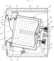
- Such a washing machine includes a tub containing water and a drum rotatably provided in the tub to accommodate the laundry.
- Recent washing machines are configured to circulate water discharged from the tub by using a circulation pump, and to spray the circulated water into the drum through a nozzle.
- EP 2 698 462 A2 relates to a washing machine.
- a method of the washing machine comprises the wash supply including laundry quantity sensing, initial water supply, laundry wetting and additional water supply.
- Related technology is shown in EP 3 214 219 A1 or WO 2014/037840 A1 .
- the present invention has been made in view of the above problems, and provides a control method of a washing machine for performing a highly concentrated washing process in the early stage of washing and performing a strong spray washing process in the middle and late stages of washing.
- the present invention further provides a control method of a washing machine which can actively perform water supply and circulation spraying in accordance with a quantity of a waste and a porosity.
- a method of controlling a washing machine according to claim 1 is provided.
- a reach range of water stream sprayed through the at least one nozzle is gradually moved from a front surface of the drum toward a rear surface.
- the rotation speed increase range of the pump motor due to the re-supply of water increases, as the sensed laundry amount becomes larger.
- the rotation speed of the pump motor is uniformly maintained while the re-supply of water is achieved.
- the water stream that is sprayed as the rotation speed of the pump motor increases reaches from a side surface portion of the drum to a rear surface portion thereof.
- the nozzle water pipe includes: a circulation pipe connection port connected to the pump to supply the pumped water; and a transfer conduit connected to the circulation pipe connection port and guiding the water introduced through the circulation pipe connection port to the nozzle.
- the transfer conduit is formed in an annular shape where a part of an upper end of a circumference is incised, and the plurality of nozzles includes: a pair of intermediate nozzles, which is disposed above a center of the gasket, for spraying the water stream downward; and a pair of lower nozzles, which is disposed below the center of the gasket, for spraying the water stream upward.
- the portion of the gasket 601 defining the inside of the cylindrical shape is referred to as the inner circumferential portion (or the inner circumferential surface) of the gasket 601, and the opposite portion is referred to as the outer circumferential portion (or the outer side surface) of the gasket 601.
- a plurality of lifters 32a may be provided on the inner side surface of the drum 32.
- the plurality of lifters 32a may be disposed at a certain angle with respect to the center of the drum 32. When the drum 32 rotates, the laundry is lifted up by the lifter 32a and then dropped repeatedly.
- the driving unit 38 includes a direct-connection type washing motor.
- the washing motor may include a stator fixed to the rear of the tub 31, and a rotor rotated by magnetic force acting between the stator and the rotor.
- the driving shaft 38a may be rotated integrally with the rotor.
- the tub 31 may be supported by a damper 16 provided in the base.
- the vibration of the tub 31 caused by the rotation of the drum 32 is attenuated by the damper 16.
- a hanger e.g., a spring for hanging the tub 31 in the casing 10 may be further provided.
- a dispenser 35 for supplying an additive such as a detergent, a fabric softening agent or the like into the tub 31 or the drum 32 may be provided.
- the additives may be separately accommodated according to their types.
- the dispenser 35 may include a detergent accommodating portion (not shown) for accommodating the detergent and a softening agent accommodating portion (not shown) for accommodating the fabric softening agent.
- At least one water supply pipe 34a, 34b, 34c for selectively guiding the water supplied through the water supply unit 33 to the respective accommodating portions of the dispenser 35 may be provided.
- the water supply unit 33 may include at least one water supply valve 94 for interrupting at least one water supply pipe 34a, 34b and 34c, respectively.
- the at least one water supply pipe 34a, 34b, 34c may include a first water supply pipe 34a for supplying cold water supplied through a cold water supply hose to the detergent accommodating portion, a second water supply pipe 34b for supplying cold water supplied through the cold water supply hose to the softening agent accommodating portion, and a third water supply pipe 34c for supplying hot water supplied through a hot water supply hose to the detergent accommodating portion.
- the gasket 601 may be provided with a direct water nozzle 42 for spraying water into the drum 32, and a direct water supply pipe 39 for guiding the water supplied through the water supply unit 33 to the direct water nozzle 42.
- the direct water nozzle 42 may be a vortex nozzle or a spray nozzle, but is not necessarily limited thereto.
- the direct water nozzle 42 may be disposed on a vertical line passing through the center of the drum 32, when viewed from the front.
- the water discharged from the dispenser 35 is supplied to the tub 31 through a water supply bellows 37.
- a water supply port (not shown) connected to the water supply bellows 37 may be formed on a side surface of the tub 31.
- the tub 31 is formed with a drainage port for discharging water, and a drainage bellows 17 may be connected to the drainage port.
- a pump 36 for pumping water discharged from the tub 31 through the drainage bellows 17 may be provided.
- a drainage valve 96 for interrupting the drainage bellows 17 may be further provided.
- the pump 36 may selectively perform the function of pumping the water discharged through the drainage bellows 17 to a drainage pipe 19, and to a circulation pipe 18 selectively.
- 'circulating water' the water which is pumped by the pump 36 and guided along the circulation pipe 18 is referred to as 'circulating water'.
- the pump 36 may include a first pump motor 92 and a second pump motor 93.
- the first pump motor 92 may be a circulation pump motor that pumps the circulating water discharged from the tub 32 to a plurality of nozzles 610b, 610c, 610d, and 610e.
- the second pump motor 93 may be a drainage pump motor for draining water from the tub 32.
- the pump 36 may vary the flow rate (or the discharge water pressure).
- the pump motors 92 and 93 may be a variable speed motor capable of controlling the rotation speed.
- Each of the pump motors 92 and 93 may be a Brushless Direct Current (BLDC) motor, but is not necessarily limited thereto.
- a driver for controlling the speed of the pump motor 92, 93 may be further provided, and the driver may be an inverter driver.
- the inverter driver converts AC power to DC power, and inputs to the motor at a target frequency.
- a controller 91 for controlling the pump motors 92 and 93 may be further provided.
- the controller may include a proportional-integral (PI) controller, a proportional-integral-derivative (PID) controller, and the like.
- the controller receives the output value (e.g., output current) of the pump motor as an input, and may control the output value of the driver so that the number of rotation of the pump motor follows a preset target number of rotation.
- the controller 91 may control not only the rotation speed of the pump motors 92 and 93 but also the rotation direction. Particularly, since the induction motor used in the conventional pump cannot control the rotation direction at the time of starting, it is difficult to control the rotation of each impeller in a set direction, and there is a problem that the flow rate discharged from a discharge port varies depending on the rotation direction of the impeller. However, since the present invention can control the rotation direction of the pump motor 92, 93 at the time of starting, the conventional problem does not occur, and the flow rate discharged through the discharge port can be uniformly controlled.
- controller 91 can control not only the pump motor 92, 93 but also the entire operation of the washing machine, and that the control of each part mentioned below is performed by the controller.
- At least one balancer 81, 82, 83, 84 may be provided on the front surface of the tub 31 along the opening of the tub 31.
- the balancer 81, 82, 83, and 84 is used to reduce the vibration of the tub 31, and is a weight body having a certain weight.
- a plurality of balancers 81, 82, 83, and 84 may be provided.
- a first upper balancer 81 and a second upper balancer 82 may be provided in the left and right sides of the upper part of the front surface of the tub 31, and a first lower balancer 83 and a second lower balancer 84 may be provided in the left and right sides of the lower part of the front surface of the tub 31.
- FIG. 4 shows an assembly of a gasket and a nozzle water pipe.
- FIG. 5 is a view of the assembly shown in FIG. 4 from a different angle.
- the gasket 601 may include a casing coupling part 61 coupled to the periphery of the loading port 12h of the casing 10, a tub coupling part 62 coupled to the periphery of the opening of the tub 31, and an extension part 63 extended between the casing coupling part 61 and the tub coupling part 62.
- the casing coupling part 61 and the tub coupling part 62 are formed in an annular shape respectively.
- the extension part 63 has an annular front end portion connected to the casing coupling part 61 and an annular rear end portion connected to the tub coupling part 62, and has a cylindrical shape extended from the front end portion to the rear end portion.
- the front panel 12 is curled outward around the loading port 12h and the casing coupling part 61 may be fitted in the concave portion formed by the curled portion.
- the casing coupling part 61 may be formed with an annular groove through which a wire is wound. After the wire is wound along the groove, both ends of the wire are bounded so that the casing coupling part 61 is firmly fixed to the periphery of the loading port 12h.
- the tub 31 is curled outward around the opening, and the tub coupling part 62 may be fitted in the concave portion formed by the curled portion.
- the tub coupling part 62 may be formed with an annular groove through which a wire is wound. After the wire is wound along the groove, the both ends of the wire are bounded, so that the tub coupling part 62 is firmly coupled to the periphery of the opening of the tub 31.
- a folding part 65 which folded as it is moved in the direction (or radial direction) in which the tub 31 is moved due to eccentricity, may be formed in a section (or the extension part 63) between the casing coupling part 61 and the tub coupling part 62.
- the drum 32 is vibrated (i.e., the rotation center line C of the drum 32 is moved) during the rotation process.
- the center line of the tub 31 (approximately, the same as the rotation center line C of the drum 32) is also moved, and at this time, the moving direction (hereinafter, referred to as "eccentric direction") has a radial component.
- the folding part 65 has a substantially Z-shaped cross section, and is folded or unfolded when the tub 31 is moved in the eccentric direction.
- a nozzle water pipe 71 guides the circulating water pumped by the pump 36 to the plurality of nozzles 610b, 610c, 610d and 610e and is fixed to the gasket 601.
- the nozzle water pipe 71 may include a circulation pipe connection port 75 connected to a circulation pipe 18a, and a transfer conduit 71c for guiding the water introduced through the circulation pipe connection port 75.
- the transfer conduit 71c is formed in an annular shape on the whole, but it may also be a shape in which a part of the circumference is cut. The portion cut on the circumference corresponds to the upper end of the first conduit part 71c1 and the upper end of the second conduit part 71c2.
- the circulation pipe connection port 75 protrudes from the transfer conduit 71c and is connected to the circulation pipe 18.
- the circulation pipe connection port 75 may protrude outward along the radial direction from the transfer conduit 71c.
- the plurality of nozzles 610b, 610c, 610d and 610e may include a pair of intermediate nozzles 610b and 610e which are disposed closer to the upper end of the gasket 601 than the lower end and spray the circulating water downward, and a pair of lower nozzles 610c and 610d which are disposed below the pair of intermediate nozzles 610b and 610e and spray the circulating water upward.
- the plurality of nozzles 610b, 610c, 610d, and 610e may further include an upper nozzle 610a (see FIG. 8 ) disposed above the pair of intermediate nozzles 610b and 610e.
- the upper nozzle 610a sprays water into the drum 32, and may spray water closer to the front surface of the drum 32 than the pair of intermediate nozzles 610b and 610e.
- the direct water nozzle 42 corresponds to the upper nozzle 610a.
- a separate upper nozzle which is connected to the nozzle water pipe 71 and sprays the circulating water pumped by the pump 36 may be provided.
- the upper nozzle is the direct water nozzle 42 (see FIG. 8 )
- the direct water nozzle 42 see FIG. 8
- the circulation pipe connection port 75 may be connected to the transfer conduit 71c from below any one of the plurality of nozzles 610b, 610c, 610d, and 610e. Preferably, the circulation pipe connection port 75 is connected to the lowermost point of the transfer conduit 71c.
- an inlet through which the water is introduced from the circulation pipe connection port 75 may be positioned at the lowermost point of the transfer conduit 71c.
- the pair of intermediate nozzles 610b and 610e may be formed above the inlet, and may be disposed in the left and right sides, respectively, based on the inlet.
- the pair of intermediate nozzles 610b and 610e are disposed symmetrically with respect to the left and right symmetry lines of the transfer conduit 71c. Accordingly, the spray directions of the respective intermediate nozzles 610b and 610e are also symmetrical with respect to the symmetry line.
- the pair of intermediate nozzles 610b and 610e may be positioned at a middle height of the nozzle water pipe 71 or above the center C of the drum 32. Since the intermediate nozzles 610b and 610e spray the circulating water downward, when the drum 32 is viewed from the front, the circulating water passes through the area above the center C of the drum 32 at the inlet side of the drum 32, and is sprayed into the drum 32 in a downwardly inclined manner.
- the pair of lower nozzles 610c and 610d are disposed above the inlet, but below the pair of intermediate nozzles 610b and 610e.
- the pair of lower nozzles 610c and 610d may be disposed in both the left and right sides based on the inlet, and are preferably disposed symmetrically with respect to a vertical line.
- the spray directions of the lower nozzles 610c and 610d are symmetric with respect to the vertical line.
- the pair of lower nozzles 610c and 610d may be positioned at a middle height of the nozzle water pipe 71c or below the center C of the drum 32. Since the lower nozzles 610c and 610d spray the circulating water upward, when the drum 32 is viewed from the front, the circulating water passes through the area below the center C of the drum 32 at the inlet side of the drum 32, and is sprayed into the drum 32 in an upwardly inclined manner.
- the controller may vary the spray pressure of the plurality of nozzles 610b, 610c, 610d, and 610e by controlling the speed of the first pump motor 92.
- the gasket 601 may be formed symmetrically with respect to a certain straight line when viewed from the front, and the upper nozzle 610a may be positioned on the straight line. Since the first nozzles 610b and 610c are disposed symmetrically with the second nozzles 610d and 610e based on the straight line, when spray is performed simultaneously through the plurality of nozzles 610b, 610c, 610d, and 610e and the upper nozzle 610a, the overall shape of the water streams sprayed through these nozzles 610a, 610b, 610c, 610d, 610e is balanced with a bilateral symmetry when viewed from the front. Therefore, when these nozzles 610a, 610b, 610c, 610d, and 610e spray simultaneously, a star-shaped spray may be implemented.
- a butterfly-shaped spray can be implemented.
- the controller varies the rotation speed of the pump motor 92 to vary the spray pressure of the plurality of nozzles 610b, 610c, 610d, and 610e.
- the spray may be implemented with a shape in which butterfly wings flutter, and thus water can be uniformly sprayed into the drum 32.
- the gasket 601 may be provided with a steam spray nozzle 47.
- the washing machine may include a steam generator (not shown) for generating steam.
- the steam spray nozzle 47 sprays steam generated by the steam generator into the drum 32.
- the nozzle water pipe 71 may be formed in an annular shape other than the above-described "Y" shape.
- the upper nozzle 610a is configured to spray the circulating water that is pumped from the pump 36, so that the plurality of nozzles 610a, 610b, 610c, 610d, and 610e can simultaneously spray the circulating water.
- FIG. 6 is a block diagram showing a control relationship between the washing machine configurations according to an embodiment of the present invention
- a user when a user inputs settings (e.g., washing course, washing, rinsing, dehydrating time, dehydrating speed, etc.) through an input unit provided on the control panel 14, and controls the washing machine to operate according to the inputted settings.
- settings e.g., washing course, washing, rinsing, dehydrating time, dehydrating speed, etc.
- a control algorithm for a water supply valve 94, a washing motor 95, a circulation pump motor 92, a drainage valve 96, and the like for each course that can be selected through the input unit may be stored in a memory (not shown), and the controller 91 may control the washing machine to operate according to an algorithm corresponding to the setting inputted through the input unit.
- the controller 91 may control not only the circulation pump motor 92 but also the drainage pump motor 93, and furthermore, may control the overall operation of the washing machine. It can be understood that the control of each part is performed under the control of the controller 91 although not mentioned.
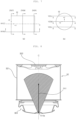
- FIG. 7A schematically shows a drum viewed from the top downward
- FIG. 7B schematically shows a drum viewed from the front.
- FIG. 7 shows that the rear direction, the upper direction, and the left direction are indicated by +Y, +X, and +Z, respectively, based on the front view of the drum 32, ZX(F) indicates the ZX plane approximately at the front surface of the drum 32, ZX(M) indicates the ZX plane approximately at the middle depth of the drum 32, and ZX(R) indicates the ZX plane approximately in the vicinity of a rear surface portion 322 of the drum 32.
- XY(R) represents the XY plane positioned at the right end of the drum 32
- XY(C) indicates the XY plane (or vertical plane) to which the center C of the drum 32 belongs.
- YZ(M) indicates the YZ plane of approximately the middle height of the drum 32
- YZ(U) indicates the YZ plane positioned above the YZ(M)
- YZ(L) indicates the YZ plane positioned below the YZ(M).
- FIG. 8 is a view showing a spray pattern of an upper nozzle taken along YZ(U) shown in FIG. 7 .
- FIG. 9A is a view of a spray pattern of an upper nozzle taken along XY(R) shown in FIG. 7
- FIG. 9B is a view taken along ZX(M) shown in FIG. 7 .
- the water stream sprayed through the upper nozzle 610a is sprayed in the form of a water film having a certain thickness, and the thickness of the water film may be defined between an upper boundary (UDL) and a lower boundary (LDL).
- UDL upper boundary
- LDL lower boundary
- the water stream shown by a dotted line in FIG. 9A indicates a case in which the water pressure becomes lower (i.e., a case in which the rotation speed of the pump motor is decreased) than that in the case where it is indicated by a solid line (in the case of the maximum water pressure).
- the intensity of the water flow also weakens.
- the area that the water stream reaches is shifted to the inlet side of the drum 32.
- the window 22 is protruded toward the drum 32 than the upper nozzle 610a. Accordingly, when the number of rotations of the pump motor becomes lower than a certain level, the water stream sprayed through the upper nozzle 610a may reach the window 22. In this case, there is an effect of cleaning the window 22.
- the water stream sprayed through the upper nozzle 610a is symmetrical with respect to XY(C), and does not reach the rear surface portion 322 of the drum 32.
- the spray direction of the upper nozzle 610a is determined according to the shape of the nozzle, even if the water pressure is continuously increased, the sprayed area cannot be deviated from a certain area.
- the water streams represented by the solid lines in FIGS. 8 to 13 show the states where the water streams are sprayed at the maximum intensity through the respective nozzles.
- the upper nozzle 610a may be configured to spray circulating water toward a side surface portion 321 of the drum 32. Specifically, the upper nozzle 610a sprays the circulating water downward toward the inside of the drum 32. At this time, the sprayed circulating water arrives at the side surface portion 321, but does not reach the rear surface portion 322. Preferably, the water stream sprayed through the upper nozzle 610a reaches the side surface portion 321 of the drum 32 in an area exceeding half the depth of the drum 32 (see FIG. 9A ).
- the spray direction of the upper nozzle 610a is represented by a vector FV1.
- the vector FV1 indicates the flow direction at the center of the water stream sprayed in the form of a water film, and is indicated based on the outlet of the upper nozzle 610a.
- the vector FV1 is oriented as shown in FIG. 8 , in the same direction as the rotation center line C when viewed from above, and as shown in FIG. 9 , when viewed from the side, forms an angle ⁇ a with respect to the rotation center line C.
- the ⁇ a is approximately 35 to 45 degrees, preferably 40 degrees.
- FIG. 10 is a view showing a spray pattern of intermediate nozzles taken along YZ(U) shown in FIG. 7 .
- FIG. 11A is a view of a first intermediate nozzle taken along XY(R) shown in FIG. 7
- FIG. 11B is a view of a spray pattern of intermediate nozzles taken along ZX(F) shown in FIG. 7
- FIG. 11C is a view taken along ZX(M)
- FIG. 11D is a view taken along ZX(R).
- the pair of intermediate nozzles 610b and 610e may include a first intermediate nozzle disposed in one side (or a first area) of the left and right sides based on the XY(C) plane and spraying the circulating water toward the other side (or a second area), and a second intermediate nozzle disposed in the other side based on the XY(C) plane and spraying the circulating water toward the one side.
- the first intermediate nozzle 610b and the second intermediate nozzle 610e are disposed symmetrically with respect to the XY(C) plane, and the spray directions of the respective intermediate nozzles are also symmetrical to each other.
- the water stream sprayed through each intermediate nozzle has a width defined between one side boundary NSL adjacent to the side where the nozzle is disposed and the other side boundary FSL opposite to the one side boundary NSL.
- the one side boundary NSL may be positioned below the other side FSL, and preferably, the one side boundary NSL meets the side surface portion 321 of the drum 32 while the other side boundary FSL meets the side surface portion 321 of the drum 32 at a higher position than the one side boundary NSL. That is, the water stream sprayed by the intermediate nozzle 610b and 610e constitutes a tilted water film which is downwardly directed to one side from the other side.
- the water stream sprayed through each of the intermediate nozzles 610b and 610e reaches an area formed between a point where one side boundary NSL meets the side surface portion 321 of the drum 32 and a point where the other side boundary FSL meets the side surface portion 321 of the drum, and the area includes an area meeting the rear surface portion 322 of the drum 32. That is, a section where the water stream meets the drum 32 passes by the rear surface portion 322 of the drum 32 while proceeding downward toward the point where one side boundary NSL meets the side surface portion 321 of the drum 32 from the point where the other side boundary FSL meets the side surface portion 321 of the drum.
- first intermediate nozzle 610b is disposed in the left side (hereinafter, referred to as "left area”) based on the XY(C) plane
- second intermediate nozzle 610e is disposed in the right side (hereinafter, referred to as "right area”) based on the XY(C) plane
- spray pattern of the intermediate nozzles 610b and 610e will be described in more detail.
- the first intermediate nozzle 610b sprays the circulating water toward the right area. That is, the water stream sprayed through the first intermediate nozzle 610b is not symmetrical with respect to the XY(C) plane but is deflected to the right side.
- the left boundary NSL (one side boundary NSL) of the water stream FL sprayed through the first intermediate nozzle 610b is positioned below the right boundary FSL (or the other side boundary FSL), and meets the side surface portion 321 of the drum 32.
- the right boundary FSL (or the other side boundary FSL) of the water stream FL sprayed through the first intermediate nozzle 610b also meets the side surface portion 321 of the drum 32.
- the right boundary FSL of the water stream FL sprayed through the first intermediate nozzle 610b meets the side surface portion 321 of the drum 32, preferably, in a position higher than the center C of the drum 32.
- the second intermediate nozzle 610e sprays the circulating water toward the left area. That is, the water stream sprayed through the second intermediate nozzle 610e is not symmetrical with respect to the XY(C) plane but is deflected to the right.
- the right boundary NSL (one side boundary NSL) of the water stream FL sprayed through the second intermediate nozzle 610e is positioned below the left boundary FSL (or the other side boundary FSL), and meets the side surface portion 321 of the drum 32.
- the left boundary FSL (or the other side boundary FSL) of the water stream FL sprayed through the second intermediate nozzle 610e also meets the side surface portion 321 of the drum 32.
- the left boundary FSL of the water stream FL sprayed through the second intermediate nozzle 610e meets the side surface portion 321 of the drum 32, preferably, in a position higher than the center C of the drum 32.
- the section where the water stream FL sprayed through the second intermediate nozzle 610e meets the drum 32 meets the rear surface portion 322 of the drum 32 while proceeding downwardly to the right from the point where the left boundary FSL meets the side surface portion 321 of the drum 32, meets again the side surface portion 321 of the drum 32 and then reaches the point where the right boundary NSL meets the side surface portion 321 of the drum 32.
- intersection section a portion (hereinafter, referred to as "intersection section") where the water stream FL sprayed from the first intermediate nozzle 610b intersects with the water stream FR sprayed from the second intermediate nozzle 610e is indicated as ISS.
- the intersection section ISS starts from the front side than the middle depth of the drum 32 and proceeds rearward and then is terminated before reaching the rear surface portion 322 of the drum 32.
- the intersection section ISS forms a line segment progressing downward from the front end to the rear end when viewed from the side (see FIG. 11A ).
- the intersection section ISS is terminated, preferably, at a depth deeper than the intermediate depth of the drum 32 (see FIG. 11C ).
- the spraying direction of the intermediate nozzle 610b, 610e is indicated by a vector FV2.
- the vector FV2 indicates the direction of flow at the center of the water stream sprayed in a water film form, based on the outlet of the intermediate nozzle 610b, 610e.
- the vector FV2 forms an angle ⁇ b1 with respect to the rotation center line C when viewed from above as shown in FIG. 10 , and forms an angle ⁇ b2 with respect to the rotation center line C when viewed from the side as shown in FIG. 39.
- the angle ⁇ b1 is approximately 5 to 15 degrees, preferably 10 degrees.
- the angle ⁇ b2 is approximately 30 to 40 degrees, preferably 34 to 35 degrees.
- the controller 91 may control the circulation pump motor 92 at a set speed so that the water stream sprayed from the pair of intermediate nozzles 610b and 610e reaches the inner side surface of the window 22, thereby cleaning the window 22.
- FIG. 12 is a view showing a spray pattern of lower nozzles taken along YZ(U) shown in FIG. 7 .
- FIG. 13A is a view of a first lower nozzle taken along XY(R) shown in FIG. 7
- FIG. 13B is a view of a spray pattern of lower nozzles taken along ZX(F) shown in FIG. 7
- FIG. 13C is a view taken along ZX(M)
- FIG. 13D is a view taken along ZX(R).
- a pair of lower nozzles 610c and 610d may include a first lower nozzle 610c which is disposed in one side (or a first area) of the left and right sides based on the XY(C) plane and sprays the circulating water toward the other side (or a second area) and a second lower nozzle 610d which is disposed in the other side based on the XY(C) plane and sprays the circulating water toward the one side.
- the first lower nozzle 610c and the second lower nozzle 610d are disposed symmetrically with respect to the XY(C) plane, and the spraying directions of the respective lower nozzles are also symmetrical to each other.
- the water stream sprayed through each lower nozzle has a width defined between one side boundary NSL near the nozzle side and the other side boundary FSL opposite to the one side boundary NSL.
- first lower nozzle 610c is disposed in the left side (hereinafter, referred to as "left area”) based on the XY(C) plane
- second lower nozzle 610d is disposed in the right side (hereinafter, referred to as "right area”) based on the XY(C) plane
- spray pattern of the lower nozzles 610c and 610d will be described in more detail.
- the first lower nozzle 610c sprays the circulating water toward the right area. That is, the water stream sprayed through the first lower nozzle 610c is not symmetrical with respect to the XY(C) plane but is deflected to the right side.
- the left boundary NSL (one side boundary NSL) of the water stream FL sprayed through the first lower nozzle 610c is positioned above the right boundary FSL (or the other side boundary FSL), and meets the rear surface portion 322 of the drum 32.
- the right boundary FSL (or the other side boundary FSL) of the water stream FL sprayed through the first lower nozzle 610c also meets the rear surface portion 322 of the drum 32.
- the left boundary NSL of the water stream FL sprayed through the first lower nozzle 610c meets the rear surface portion 322 of the drum 32, preferably, in a position higher than the center C of the drum 32.
- the right boundary FSL of the water stream FL sprayed through the first lower nozzle 610c meets the rear surface portion 322 of the drum 32, preferably, in a position lower than the center C of the drum 32.
- the section where the water stream FL sprayed through the first lower nozzle 610c reaches the point where the right boundary FSL meets the rear surface portion 322 of the drum 32 while proceeding downwardly to the right from the point where the left boundary NSL meets the rear surface portion 322 of the drum 32.
- the second lower nozzle 610d sprays the circulating water toward the right area. That is, the water stream sprayed through the second lower nozzle 610d is not symmetrical with respect to the XY(C) plane but is deflected to the right.
- the right boundary NSL (one side boundary NSL) of the water stream FL sprayed through the second lower nozzle 610d is positioned above the left boundary FSL (or the other side boundary FSL), and meets the rear surface portion 322 of the drum 32.
- the left boundary FSL (or the other side boundary FSL) of the water stream FL sprayed through the second lower nozzle 610d also meets the rear surface portion 322 of the drum 32.
- the right boundary NSL of the water stream FL sprayed through the second lower nozzle 610d meets the rear surface portion 322 of the drum 32, preferably, in a position higher than the center C of the drum 32.
- the left boundary NSL of the water stream FL sprayed through the first lower nozzle 610c meets the rear surface portion 322 of the drum 32, preferably, in a position lower than the center C of the drum 32.
- the section where the water stream FL sprayed through the second lower nozzle 610d meets the drum 32 reaches the point where the left boundary FSL meets the rear surface portion 322 of the drum 32, while proceeding downwardly to the left from the point where the left boundary NSL meets the rear surface portion 322 of the drum 32.
- intersection section a portion (hereinafter, referred to as "intersection section") where the water stream FL sprayed from the first lower nozzle 610c intersects with the water stream FR sprayed from the second lower nozzle 610d is indicated as ISS.
- the intersection section (ISS) forms a line segment upward from the front end to the rear end when viewed from the side (see FIG. 13A ).
- the intersection section ISS preferably is terminated at a depth deeper than the middle depth of the drum 32 (preferably, closer to the rear surface portion 322 than the middle depth of the drum 32) (see FIG. 13D ).
- the spraying direction of the lower nozzle 610c, 610d is indicated by a vector FV3.
- the vector FV3 indicates the direction of flow at the center of the water stream sprayed in a water film form, based on the outlet of the intermediate nozzle 610c, 610d.
- the vector FV3 forms an angle ⁇ c1 with respect to the rotation center line C when viewed from above as shown in FIG. 12 , and forms an angle ⁇ c2 with respect to the rotation center line C when viewed from the side as shown in FIG. 13 .
- the angle ⁇ c1 is approximately 15 to 25 degrees, preferably 20 degrees.
- the angle ⁇ c2 is approximately 20 to 30 degrees, preferably 25 to 26 degrees.
- FIG. 14 is a view for explaining a spray range of a nozzle according to a rotation speed of a circulation pump motor according to an embodiment of the present invention.
- FIG. 14 shows the spray range of the water stream sprayed from the intermediate nozzle 610b, 610e and the lower nozzle 610c, 610d that spray water into the drum 32 as the circulation pump motor 92 rotates.
- the water stream sprayed from the nozzle 610b, 610c, 610d, 610e reaches the first area of the side surface portion 321 of the drum 32.
- the water stream sprayed from the intermediate nozzle 610b, 610e reaches the second area
- the water stream sprayed from the lower nozzle 610c, 610d reaches the second area.
- the water stream sprayed from the nozzle 610b, 610c, 610d, 610e reaches the third area.
- the water stream reaches the rear surface portion 322 of the drum 32.
- the water stream reaches 1/3 of the height H of the drum 32.
- the water stream reaches 2/3 of the height H of the drum 32.
- the rotation speed of the circulation pump motor 92 reaches 3500 rpm, the height of the water stream becomes the maximum and, structurally, the spraying height of the nozzle 610b, 610c, 610d, 610e can not be increased any more, but only the intensity of the water stream can be strengthened.
- the rotation speed value Rpm of the circulation pump motor 92 in FIG. 15 is a value according to an embodiment of the present invention, which may vary depending on the size and shape of the water supply pipe, and the specification of the pump. However, as the rotation speed of the circulation pump motor 92 is increased as shown in FIG. 14 , the tendency of the water stream reaching the upper side of the rear surface portion 322 from the front of the drum 32 may be the same.
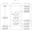
- FIG. 15 is a flowchart showing a change of the pump RPM due to re-supply of water.
- FIG. 16 is a graph showing the relationship between the driving of washing motor, the pump motor RPM, and the point of re-supply of water.
- the water supply is performed in such a manner that the minimum amount of residual water that may be circulated by the pump 36 is added to the minimum amount of laundry wetting water that can completely wet the laundry.
- Such a high-concentration washing has an advantage, even in the heating process, in that as the amount of washing water becomes smaller, the temperature of the washing water can be raised faster, and the amount of power consumed for heating can be reduced.
- the minimum level at which the heater can be completely sunk must be maintained to prevent breakage and safety accidents due to overheating of the heater.
- the early stage of the washing cycle is a preparation process for the main washing, and a high-concentration washing process is suitable for this stage.
- more powerful spraying and circulating of washing water is required. This is because the purpose of the main washing process is to clean the laundry by removing contaminants attached to the laundry. Therefore, preferably, a small amount of residual water (the water that is not absorbed by the laundry and remained in the tub) is maintained in the early stage of the washing process, and then a larger amount of washing water is circulated through the re-supply of water while progressing to the later stage of the washing process, and at the same time, the pump RPM is increased to strengthen the mechanical force, so that the intensive spray washing is performed.
- the present invention proposes a method for automatically controlling the re-supply of water, the number of times of the re-supply of water, and the increase of pump RPM due to the re-supply of water.
- the intensity of the water sprayed through the circulation nozzle is adjusted in response to the change in the water level in the drum, the water level in the drum is maintained at a low level in the early stage of washing process and the washing is performed with the high concentration washing water. Then, in the later stage of the washing, the washing effect can be improved by performing washing by gradually raising a water level
- the rotation speed of the pump motor when the rotation speed of the pump motor is uniformly maintained at a high speed, the water level in the drum is lowered and re-supply of water is required. In this case, the amount of water used for washing may increase and the concentration of the detergent water may also be lowered. According to the embodiment of the present invention, by changing the rotation speed of the pump motor according to the water level in the drum, the amount of water used for washing can be reduced, and the high concentration washing can be performed at a low water level in the early stage of washing.
- the water pressure sprayed through the nozzle may be improved, and the washing effect may be enhanced by the physical impact due to the water pressure.
- the laundry amount may be determined based on the principle that the rotation inertia of the drum 32 varies depending on the amount of the laundry loaded into the drum 32. For example, in the process of accelerating the washing motor 95, the amount of the laundry may be obtained based on the time taken to reach a preset target speed, obtained based on the acceleration slope of the washing motor 95, obtained based on the deceleration slope, or obtained based on the counter electromotive force in braking power generation.
- various methods for obtaining the laundry amount have been known in the field of washing machine technology. Accordingly, it is obvious that those known technologies can be applied.
- the controller 91 supplies the washing water into the drum 32 (S3).
- the water supply is performed by opening the water supply valve 94, and the water supply may be performed up to a set water level.
- the set water level may be set according to the laundry amount sensed in step S2.
- the set water level may be set in proportion to the laundry amount.
- the set water level may be a value obtained by substituting the laundry amount into a preset table or an equation.
- the initial rotation speed may be determined by the laundry amount, and the initial rotation speed in the case of a large laundry amount may be set higher than that in the case of a small laundry amount. Particularly, in the case of a small laundry amount, since most of the laundry moves at the front portion of the drum 32, the water stream sprayed from the nozzle does not need to reach the rear surface of the drum 32.
- the washing water is circulated through the circulation pump motor 92.
- washing water is sprayed into the drum 32 through at least one nozzle 610b, 610c, 610d, and 610e.
- the drum is also rotated by the washing motor 95, the laundry positioned in the drum is moved.
- the drum is driven by the combination of the rotation direction and the rotation speed of the washing motor 95, and the various driving motions of the drum are determined by the variety of rotation direction and rotation speed.
- the movement of the laundry inside the drum varies depending on the type of the drum driving motion.
- the controller 91 may control the water supply valve 94 to be opened to perform the re-supply of water.
- the washing water supplied through the water supply valve 94 may be sprayed through the direct water nozzle 42.
- the amount of washing water may be gradually increased through the re-supply of water.
- a preset water amount may be re-supplied every time, and the preset water amount may not be limited to a specific value but may be a value adjusted according to various conditions (e.g., laundry amount).
- the rotation speed rpm of the circulation pump motor 92 is raised by the controller 91 that sensed the re-supply of water (S9). Not only the washing water amount is increased due to the re-supply of water, but also the rotation speed of the circulation pump motor 92 is increased, so that the circulating flow rate is increased and the intensity of the water stream or the spraying intensity sprayed through at least one of the nozzles 610b, 610c, 610d, and 610e is also increased.
- the mechanical force for the laundry may be increased stepwise.
- the timing and the number of times of the re-supply of water and the increase of the rotation speed of the circulation pump motor 92 are not performed at a specific point of time and a specific number of times, but the timing and the number of times of the re-supply of water are automatically determined through determination of the water level, and thus, the increase of the rotation speed of the pump motor may be performed flexibly depending on the re-supply of water.
- the re-supply of water is not performed any more, and the rpm increase of the circulation pump motor 92 due to the re-supply of water is not performed.
- the washing process may be performed without any further re-supply of water. Accordingly, the rotation speed (rpm) of the circulation pump motor 92 is also maintained at a constant speed.
- the present invention has an algorithm for changing the high-concentration washing process in the early and mid stages of the washing to a mechanical power washing process through the re-supply of water and the increase of the pump rpm while progressing toward the later stage of the washing, and thus has to maximize the washing effect by performing the washing process through the strong spray of washing water in the later stage of the washing.
- the rotation speed of the circulation pump motor 92 may increase stepwise by the number of times of the re-supply of water to approach the maximum rotation speed.
- the pump motor may be rotated at a preset maximum rotation speed in the later stage of washing. This is because in some cases, it is not necessary to perform the re-supply of water, and sometimes the re-supply of water is required several times, and thus it is necessary to be able to perform the strong spay washing while the rotation speed of the pump motor in the later stage of the washing is maintained at the maximum rotation speed irrespective of the re-supply of water.
- the rotation of the circulation pump motor 92 due to the re-supply of water is intermittently repeated. Therefore, the circulation of the washing water due to the re-supply of water may occur periodically.
- the pump motor may also be stopped (S13).
Landscapes
- Engineering & Computer Science (AREA)
- Textile Engineering (AREA)
- Detail Structures Of Washing Machines And Dryers (AREA)
Claims (18)
- Verfahren zum Steuern einer Waschmaschine, die aufweist: einen Bottich (31), der in einem Gehäuse (10) angeordnet ist und eine Öffnung aufweist, die an einer Vorderseite desselben ausgebildet ist, so dass Wäsche geladen werden kann, eine Trommel (32), die drehbar in dem Bottich (31) vorgesehen ist und konfiguriert ist, Wäsche darin aufzunehmen, mehrere Düsen (610b, 610c, 610d, 610e), die konfiguriert sind, zirkulierendes Wasser in den Bottich (31) zu sprühen, eine Pumpe (36), die mindestens einen Pumpenmotor (92) aufweist, wobei die Pumpe (36) konfiguriert ist, das aus dem Bottich (31) abgegebene zirkulierende Wasser zu den mehreren Düsen (610b, 610c, 610d, 610e) zu fördern, wobei das Verfahren aufweist:einen Schritt (S2) des Erfassens einer in der Trommel (32) aufgenommenen Wäschemenge;einen Schritt (S3) des Durchführens einer Wasserzufuhr in die Trommel (32) entsprechend der erfassten Wäschemenge;einen Schritt (S4) des Drehens des Pumpenmotors (92) mit einer bestimmten anfänglichen Drehzahl und des Transferierens von aus der Trommel (32) abgegebenem Waschwasser zu den mehreren Düsen (610b, 610c, 610d, 610e) zum Sprühen von Wasser in die Trommel (32);einen Schritt (S6) des Erfassens eines Wasserstands in der Trommel (32); undeinen Schritt (S8) des Durchführens einer erneuten Wasserzufuhr mindestens einmal, bis der erfasste Wasserstand einen eingestellten Wasserstand erreicht;dadurch gekennzeichnet, dass das Verfahren ferner einen Schritt (S9) des Erhöhens der Drehzahl des Pumpenmotors (92) aufweist, wann immer die erneute Wasserzufuhr durchgeführt wird.
- Verfahren nach Anspruch 1, das ferner aufweist:nach dem Drehen (S9) des Pumpenmotors (92) mit der ersten Drehzahl, Erfassen (S6) des Wasserstands in der Trommel (32);Durchführen (S8) einer erneuten Wasserzufuhr, wenn der erfasste Wasserstand nicht den eingestellten Wasserstand erreicht; undDrehen (S9) des Pumpenmotors (92) mit einer zweiten Drehzahl, die höher ist als die erste Drehzahl.
- Verfahren nach Anspruch 1 oder 2, wobei, wenn die Drehzahl des Pumpenmotors (92) zunimmt, eine Reichweite des durch die mehreren Düsen (610b, 610c, 610d, 610e) gesprühten Wasserstroms allmählich von einer Vorderseite der Trommel (32) zu einer Rückseite bewegt wird.
- Verfahren nach einem der Ansprüche 1 bis 3, das ferner das Drehen (S10) des Pumpenmotors (92) mit einer eingestellten maximalen Drehzahl aufweist, nachdem der Wasserstand des Waschwassers den eingestellten Wasserstand erreicht hat.
- Verfahren nach Anspruch 4, wobei die maximale Drehzahl höher eingestellt wird, wenn die erfasste Wäschemenge größer wird.
- Verfahren nach einem der Ansprüche 1 bis 5, wobei ein Drehzahl-Zunahmebereich des Pumpenmotors (92) aufgrund der erneuten Wasserzufuhr zunimmt, wenn die erfasste Wäschemenge größer wird.
- Verfahren nach einem der Ansprüche 1 bis 6, wobei die anfängliche Drehzahl des Pumpenmotors (92) höher eingestellt wird, wenn die erfasste Wäschemenge größer wird.
- Verfahren nach einem der Ansprüche 1 bis 7, wobei der eingestellte Wasserstand höher eingestellt wird, wenn die erfasste Wäschemenge größer wird.
- Verfahren nach einem der Ansprüche 1 bis 8, wobei der Wasserstand in der Trommel (92) in einem Zustand erfasst wird (S6), in dem ein Waschmotor zum Drehen der Trommel (32) ausgeschaltet ist.
- Verfahren nach einem der Ansprüche 1 bis 9, das ferner das Durchführen einer zusätzlichen Wasserzufuhr aufweist, wenn der Wasserstand in der Trommel (32) unter einen bestimmten Wasserstand abgesenkt wird, nachdem die erneute Wasserzufuhr durchgeführt wurde und der Wasserstand den eingestellten Wasserstand erreicht.
- Verfahren nach einem der Ansprüche 1 bis 10, wobei die Drehung des Pumpenmotors (92) wiederholt intermittierend durchgeführt wird.
- Verfahren nach einem der Ansprüche 1 bis 9, wobei die Drehzahl des Pumpenmotors (92) gleichmäßig aufrechterhalten wird, während die erneute Wasserzufuhr ausgeführt wird.
- Verfahren nach einem der Ansprüche 1 bis 12, wobei in dem Wasserstrom, der durch die mehreren Düsen gesprüht wird, der Wasserstrom, der gesprüht wird, wenn die Drehzahl des Pumpenmotors (92) zunimmt, von einem Seitenflächenabschnitt der Trommel (32) zu einem hinteren Oberflächenabschnitt derselben reicht.
- Verfahren nach einem der Ansprüche 1 bis 13, wobei die Waschmaschine aufweist:eine ringförmige Dichtung (601), die das Gehäuse (10) und die Öffnung des Bottichs (31) verbindet; undein Düsenwasserrohr (71), das an der Dichtung (601) befestigt ist, um von der Pumpe (36) gepumptes Wasser zu den mehreren Düsen (610b, 610c, 610d, 610e) zu leiten, wobei das Düsenwasserrohr (71) aufweist:eine Zirkulationsrohr-Verbindungsanschluss (75), der mit der Pumpe (36) verbunden ist, um das gepumpte Wasser zuzuführen; undeine Transferleitung (71c), die mit dem Zirkulationsrohr-Verbindungsanschluss (75) verbunden ist und das durch den Zirkulationsrohr-Verbindungsanschluss (75) eingeleitete Wasser zu den mehreren Düsen (610b, 610c, 610d, 610e) leitet.
- Verfahren nach Anspruch 14, wobei die Transferleitung (71c) ringförmig ausgebildet ist, wobei ein Teil eines oberen Endes eines Umfangs eingeschnitten ist, und das Wasser, das zu dem Zirkulationsrohr-Verbindungsanschluss (75) gepumpt wird, der an dem unteren Ende der Transferleitung (71c) angeordnet ist, verzweigt und in beide Richtungen durch die Transferleitung (71c) geführt wird.
- Verfahren nach Anspruch 14, wobei die Transferleitung (71c) ringförmig ausgebildet ist, wobei ein Teil eines oberen Endes eines Umfangs eingeschnitten ist, wobei die mehreren Düsen (610b, 610c, 610d, 610e) aufweisen:ein Paar Zwischendüsen (610b, 610e), das über einer Mitte der Dichtung (601) angeordnet ist, um den Wasserstrom nach unten zu sprühen; undein Paar untere Düsen (610c, 610d), das unter der Mitte der Dichtung (601) angeordnet ist, um den Wasserstrom nach oben zu sprühen.
- Verfahren nach Anspruch 16, wobei das Paar Zwischendüsen (610b, 610e) und das Paar untere Düsen (610c, 610d) mit der linken und rechten Seite der Transferleitung (71c) verbunden sind, so dass in die Transferleitung (71c) eingeleitetes Wasser durch das Paar Zwischendüsen (610b, 610e) und das Paar untere Düsen (610c, 610d) in die Trommel (32) gesprüht wird.
- Verfahren nach Anspruch 16 oder 17, wobei der Zirkulationsrohr-Verbindungsanschluss (75) an einem unteren Ende der Transferleitung (71c) angeordnet ist und das zu dem Zirkulationsrohr-Verbindungsanschluss (75) gepumpte Wasser abgezweigt und in beide Richtungen durch die Transferleitung (71c) geleitet wird.
Applications Claiming Priority (1)
| Application Number | Priority Date | Filing Date | Title |
|---|---|---|---|
| KR1020180047041A KR102577756B1 (ko) | 2018-04-24 | 2018-04-24 | 세탁기의 제어방법 |
Publications (2)
| Publication Number | Publication Date |
|---|---|
| EP3569755A1 EP3569755A1 (de) | 2019-11-20 |
| EP3569755B1 true EP3569755B1 (de) | 2025-03-26 |
Family
ID=66248578
Family Applications (1)
| Application Number | Title | Priority Date | Filing Date |
|---|---|---|---|
| EP19170523.5A Active EP3569755B1 (de) | 2018-04-24 | 2019-04-23 | Waschmaschine und steuerungsverfahren dafür |
Country Status (5)
| Country | Link |
|---|---|
| US (1) | US11421366B2 (de) |
| EP (1) | EP3569755B1 (de) |
| KR (1) | KR102577756B1 (de) |
| AU (1) | AU2019261205B2 (de) |
| WO (1) | WO2019209024A1 (de) |
Families Citing this family (7)
| Publication number | Priority date | Publication date | Assignee | Title |
|---|---|---|---|---|
| KR102771771B1 (ko) * | 2019-06-28 | 2025-02-20 | 엘지전자 주식회사 | 세탁기의 제어방법 |
| KR102887255B1 (ko) | 2019-10-04 | 2025-11-14 | 주식회사 엘지에너지솔루션 | 배터리 진단 시스템 및 방법 |
| KR20210122718A (ko) * | 2020-04-01 | 2021-10-12 | 엘지전자 주식회사 | 의류처리장치 |
| US12473683B2 (en) * | 2020-04-01 | 2025-11-18 | Lg Electronics Inc. | Clothing treatment apparatus |
| DE102020212699A1 (de) * | 2020-10-08 | 2022-04-14 | BSH Hausgeräte GmbH | Wäschebehandlungsgerät mit bedampfungsfunktion und verfahren zum bedampfen von wäsche |
| CN113514382B (zh) * | 2021-04-25 | 2024-04-05 | 西南石油大学 | 评价含膨胀粘土气藏岩石水相渗吸返排后水膜厚度的方法 |
| US12410552B2 (en) * | 2021-05-17 | 2025-09-09 | Whirlpool Corporation | Three-dimensional steam generating system for performing a steam cycle within a laundry appliance |
Family Cites Families (14)
| Publication number | Priority date | Publication date | Assignee | Title |
|---|---|---|---|---|
| KR100505255B1 (ko) | 2003-05-02 | 2005-08-02 | 엘지전자 주식회사 | 드럼세탁기의 수위감지방법 |
| KR20050012526A (ko) * | 2003-07-25 | 2005-02-02 | 엘지전자 주식회사 | 드럼세탁기의 제어방법 |
| KR101073505B1 (ko) * | 2006-08-14 | 2011-10-17 | 삼성전자주식회사 | 세탁기 및 그 수위제어방법 |
| JP2009006081A (ja) | 2007-06-29 | 2009-01-15 | Toshiba Corp | 洗濯機 |
| JP5142838B2 (ja) * | 2008-06-11 | 2013-02-13 | 株式会社東芝 | 洗濯機 |
| US8776297B2 (en) | 2009-10-13 | 2014-07-15 | Lg Electronics Inc. | Laundry treating apparatus and method |
| US9045853B2 (en) | 2009-10-13 | 2015-06-02 | Lg Electronics Inc. | Laundry treating apparatus |
| CN103547726B (zh) * | 2011-04-14 | 2016-07-13 | Lg电子株式会社 | 洗衣机 |
| JP5873968B2 (ja) * | 2011-09-05 | 2016-03-01 | パナソニックIpマネジメント株式会社 | 洗濯機 |
| ES2446115B1 (es) | 2012-09-06 | 2015-03-06 | Bsh Electrodomesticos Espana | Junta anular de embocadura para una máquina lavadora de carga frontal con sistema de remojado de colada y máquina lavadora de carga frontal que comprende la junta |
| EP2961879A1 (de) | 2013-02-28 | 2016-01-06 | Arçelik Anonim Sirketi | Wasch- und spülsystem für eine waschmaschine mit verbesserter effizienz |
| KR102196182B1 (ko) * | 2014-10-27 | 2020-12-29 | 엘지전자 주식회사 | 세탁기 |
| KR101708665B1 (ko) * | 2015-10-02 | 2017-02-21 | 엘지전자 주식회사 | 세탁기의 제어방법 |
| KR102127844B1 (ko) | 2015-10-02 | 2020-06-29 | 엘지전자 주식회사 | 세탁기 |
-
2018
- 2018-04-24 KR KR1020180047041A patent/KR102577756B1/ko active Active
-
2019
- 2019-04-23 US US16/392,197 patent/US11421366B2/en active Active
- 2019-04-23 EP EP19170523.5A patent/EP3569755B1/de active Active
- 2019-04-24 AU AU2019261205A patent/AU2019261205B2/en active Active
- 2019-04-24 WO PCT/KR2019/004948 patent/WO2019209024A1/en not_active Ceased
Also Published As
| Publication number | Publication date |
|---|---|
| US11421366B2 (en) | 2022-08-23 |
| AU2019261205B2 (en) | 2022-07-07 |
| KR102577756B1 (ko) | 2023-09-11 |
| US20190323161A1 (en) | 2019-10-24 |
| AU2019261205A1 (en) | 2020-12-24 |
| WO2019209024A1 (en) | 2019-10-31 |
| KR20190123392A (ko) | 2019-11-01 |
| EP3569755A1 (de) | 2019-11-20 |
Similar Documents
| Publication | Publication Date | Title |
|---|---|---|
| EP3569755B1 (de) | Waschmaschine und steuerungsverfahren dafür | |
| US12215453B2 (en) | Washing machine | |
| AU2022204628B2 (en) | Washing machine and method for controlling the same | |
| KR102513380B1 (ko) | 세탁기의 제어방법 | |
| KR102230689B1 (ko) | 세탁기의 제어방법 | |
| KR20180076565A (ko) | 세탁기의 제어방법 | |
| CN114051545B (zh) | 洗衣机及洗衣机的控制方法 | |
| CN114041000B (zh) | 洗衣机及洗衣机的控制方法 | |
| KR20190001844A (ko) | 세탁기의 제어방법 | |
| KR20180076561A (ko) | 세탁기의 제어방법 | |
| KR102367613B1 (ko) | 세탁기 | |
| EP3842581B1 (de) | Waschmaschine | |
| KR20180076563A (ko) | 세탁기의 제어방법 | |
| KR20180076562A (ko) | 세탁기의 제어방법 |
Legal Events
| Date | Code | Title | Description |
|---|---|---|---|
| PUAI | Public reference made under article 153(3) epc to a published international application that has entered the european phase |
Free format text: ORIGINAL CODE: 0009012 |
|
| STAA | Information on the status of an ep patent application or granted ep patent |
Free format text: STATUS: REQUEST FOR EXAMINATION WAS MADE |
|
| 17P | Request for examination filed |
Effective date: 20190523 |
|
| AK | Designated contracting states |
Kind code of ref document: A1 Designated state(s): AL AT BE BG CH CY CZ DE DK EE ES FI FR GB GR HR HU IE IS IT LI LT LU LV MC MK MT NL NO PL PT RO RS SE SI SK SM TR |
|
| AX | Request for extension of the european patent |
Extension state: BA ME |
|
| RBV | Designated contracting states (corrected) |
Designated state(s): AL AT BE BG CH CY CZ DE DK EE ES FI FR GB GR HR HU IE IS IT LI LT LU LV MC MK MT NL NO PL PT RO RS SE SI SK SM TR |
|
| STAA | Information on the status of an ep patent application or granted ep patent |
Free format text: STATUS: EXAMINATION IS IN PROGRESS |
|
| 17Q | First examination report despatched |
Effective date: 20211027 |
|
| REG | Reference to a national code |
Ref country code: DE Ref legal event code: R079 Free format text: PREVIOUS MAIN CLASS: D06F0033020000 Ipc: D06F0033460000 Ref country code: DE Ref legal event code: R079 Ref document number: 602019067677 Country of ref document: DE Free format text: PREVIOUS MAIN CLASS: D06F0033020000 Ipc: D06F0033460000 |
|
| RIC1 | Information provided on ipc code assigned before grant |
Ipc: D06F 103/18 20200101ALN20241024BHEP Ipc: D06F 105/48 20200101ALN20241024BHEP Ipc: D06F 105/06 20200101ALN20241024BHEP Ipc: D06F 105/02 20200101ALN20241024BHEP Ipc: D06F 103/04 20200101ALN20241024BHEP Ipc: D06F 101/20 20200101ALN20241024BHEP Ipc: D06F 101/14 20200101ALN20241024BHEP Ipc: D06F 101/10 20200101ALN20241024BHEP Ipc: D06F 35/00 20060101ALN20241024BHEP Ipc: D06F 37/26 20060101ALN20241024BHEP Ipc: D06F 33/46 20200101AFI20241024BHEP |
|
| GRAP | Despatch of communication of intention to grant a patent |
Free format text: ORIGINAL CODE: EPIDOSNIGR1 |
|
| STAA | Information on the status of an ep patent application or granted ep patent |
Free format text: STATUS: GRANT OF PATENT IS INTENDED |
|
| INTG | Intention to grant announced |
Effective date: 20241202 |
|
| GRAS | Grant fee paid |
Free format text: ORIGINAL CODE: EPIDOSNIGR3 |
|
| GRAA | (expected) grant |
Free format text: ORIGINAL CODE: 0009210 |
|
| STAA | Information on the status of an ep patent application or granted ep patent |
Free format text: STATUS: THE PATENT HAS BEEN GRANTED |
|
| AK | Designated contracting states |
Kind code of ref document: B1 Designated state(s): AL AT BE BG CH CY CZ DE DK EE ES FI FR GB GR HR HU IE IS IT LI LT LU LV MC MK MT NL NO PL PT RO RS SE SI SK SM TR |
|
| REG | Reference to a national code |
Ref country code: GB Ref legal event code: FG4D |
|
| REG | Reference to a national code |
Ref country code: CH Ref legal event code: EP |
|
| REG | Reference to a national code |
Ref country code: DE Ref legal event code: R096 Ref document number: 602019067677 Country of ref document: DE |
|
| REG | Reference to a national code |
Ref country code: IE Ref legal event code: FG4D |
|
| PG25 | Lapsed in a contracting state [announced via postgrant information from national office to epo] |
Ref country code: RS Free format text: LAPSE BECAUSE OF FAILURE TO SUBMIT A TRANSLATION OF THE DESCRIPTION OR TO PAY THE FEE WITHIN THE PRESCRIBED TIME-LIMIT Effective date: 20250626 |
|
| PG25 | Lapsed in a contracting state [announced via postgrant information from national office to epo] |
Ref country code: FI Free format text: LAPSE BECAUSE OF FAILURE TO SUBMIT A TRANSLATION OF THE DESCRIPTION OR TO PAY THE FEE WITHIN THE PRESCRIBED TIME-LIMIT Effective date: 20250326 |
|
| PGFP | Annual fee paid to national office [announced via postgrant information from national office to epo] |
Ref country code: DE Payment date: 20250407 Year of fee payment: 7 |
|
| REG | Reference to a national code |
Ref country code: LT Ref legal event code: MG9D |
|
| PG25 | Lapsed in a contracting state [announced via postgrant information from national office to epo] |
Ref country code: NO Free format text: LAPSE BECAUSE OF FAILURE TO SUBMIT A TRANSLATION OF THE DESCRIPTION OR TO PAY THE FEE WITHIN THE PRESCRIBED TIME-LIMIT Effective date: 20250626 |
|
| PG25 | Lapsed in a contracting state [announced via postgrant information from national office to epo] |
Ref country code: HR Free format text: LAPSE BECAUSE OF FAILURE TO SUBMIT A TRANSLATION OF THE DESCRIPTION OR TO PAY THE FEE WITHIN THE PRESCRIBED TIME-LIMIT Effective date: 20250326 |
|
| PG25 | Lapsed in a contracting state [announced via postgrant information from national office to epo] |
Ref country code: LV Free format text: LAPSE BECAUSE OF FAILURE TO SUBMIT A TRANSLATION OF THE DESCRIPTION OR TO PAY THE FEE WITHIN THE PRESCRIBED TIME-LIMIT Effective date: 20250326 |
|
| PG25 | Lapsed in a contracting state [announced via postgrant information from national office to epo] |
Ref country code: GR Free format text: LAPSE BECAUSE OF FAILURE TO SUBMIT A TRANSLATION OF THE DESCRIPTION OR TO PAY THE FEE WITHIN THE PRESCRIBED TIME-LIMIT Effective date: 20250627 Ref country code: BG Free format text: LAPSE BECAUSE OF FAILURE TO SUBMIT A TRANSLATION OF THE DESCRIPTION OR TO PAY THE FEE WITHIN THE PRESCRIBED TIME-LIMIT Effective date: 20250326 |
|
| REG | Reference to a national code |
Ref country code: NL Ref legal event code: MP Effective date: 20250326 |
|
| PG25 | Lapsed in a contracting state [announced via postgrant information from national office to epo] |
Ref country code: NL Free format text: LAPSE BECAUSE OF FAILURE TO SUBMIT A TRANSLATION OF THE DESCRIPTION OR TO PAY THE FEE WITHIN THE PRESCRIBED TIME-LIMIT Effective date: 20250326 |
|
| PG25 | Lapsed in a contracting state [announced via postgrant information from national office to epo] |
Ref country code: SE Free format text: LAPSE BECAUSE OF FAILURE TO SUBMIT A TRANSLATION OF THE DESCRIPTION OR TO PAY THE FEE WITHIN THE PRESCRIBED TIME-LIMIT Effective date: 20250326 |
|
| REG | Reference to a national code |
Ref country code: AT Ref legal event code: MK05 Ref document number: 1779069 Country of ref document: AT Kind code of ref document: T Effective date: 20250326 |
|
| PG25 | Lapsed in a contracting state [announced via postgrant information from national office to epo] |
Ref country code: SM Free format text: LAPSE BECAUSE OF FAILURE TO SUBMIT A TRANSLATION OF THE DESCRIPTION OR TO PAY THE FEE WITHIN THE PRESCRIBED TIME-LIMIT Effective date: 20250326 |
|
| PG25 | Lapsed in a contracting state [announced via postgrant information from national office to epo] |
Ref country code: PT Free format text: LAPSE BECAUSE OF FAILURE TO SUBMIT A TRANSLATION OF THE DESCRIPTION OR TO PAY THE FEE WITHIN THE PRESCRIBED TIME-LIMIT Effective date: 20250728 Ref country code: ES Free format text: LAPSE BECAUSE OF FAILURE TO SUBMIT A TRANSLATION OF THE DESCRIPTION OR TO PAY THE FEE WITHIN THE PRESCRIBED TIME-LIMIT Effective date: 20250326 |
|
| PG25 | Lapsed in a contracting state [announced via postgrant information from national office to epo] |
Ref country code: PL Free format text: LAPSE BECAUSE OF FAILURE TO SUBMIT A TRANSLATION OF THE DESCRIPTION OR TO PAY THE FEE WITHIN THE PRESCRIBED TIME-LIMIT Effective date: 20250326 Ref country code: IT Free format text: LAPSE BECAUSE OF FAILURE TO SUBMIT A TRANSLATION OF THE DESCRIPTION OR TO PAY THE FEE WITHIN THE PRESCRIBED TIME-LIMIT Effective date: 20250326 |
|
| PG25 | Lapsed in a contracting state [announced via postgrant information from national office to epo] |
Ref country code: AT Free format text: LAPSE BECAUSE OF FAILURE TO SUBMIT A TRANSLATION OF THE DESCRIPTION OR TO PAY THE FEE WITHIN THE PRESCRIBED TIME-LIMIT Effective date: 20250326 |
|
| PG25 | Lapsed in a contracting state [announced via postgrant information from national office to epo] |
Ref country code: EE Free format text: LAPSE BECAUSE OF FAILURE TO SUBMIT A TRANSLATION OF THE DESCRIPTION OR TO PAY THE FEE WITHIN THE PRESCRIBED TIME-LIMIT Effective date: 20250326 |
|
| PG25 | Lapsed in a contracting state [announced via postgrant information from national office to epo] |
Ref country code: RO Free format text: LAPSE BECAUSE OF FAILURE TO SUBMIT A TRANSLATION OF THE DESCRIPTION OR TO PAY THE FEE WITHIN THE PRESCRIBED TIME-LIMIT Effective date: 20250326 |
|
| PG25 | Lapsed in a contracting state [announced via postgrant information from national office to epo] |
Ref country code: SK Free format text: LAPSE BECAUSE OF FAILURE TO SUBMIT A TRANSLATION OF THE DESCRIPTION OR TO PAY THE FEE WITHIN THE PRESCRIBED TIME-LIMIT Effective date: 20250326 |
|
| PG25 | Lapsed in a contracting state [announced via postgrant information from national office to epo] |
Ref country code: IS Free format text: LAPSE BECAUSE OF FAILURE TO SUBMIT A TRANSLATION OF THE DESCRIPTION OR TO PAY THE FEE WITHIN THE PRESCRIBED TIME-LIMIT Effective date: 20250726 |
|
| REG | Reference to a national code |
Ref country code: CH Ref legal event code: H13 Free format text: ST27 STATUS EVENT CODE: U-0-0-H10-H13 (AS PROVIDED BY THE NATIONAL OFFICE) Effective date: 20251125 |
|
| PG25 | Lapsed in a contracting state [announced via postgrant information from national office to epo] |
Ref country code: LU Free format text: LAPSE BECAUSE OF NON-PAYMENT OF DUE FEES Effective date: 20250423 |
|
| PG25 | Lapsed in a contracting state [announced via postgrant information from national office to epo] |
Ref country code: MC Free format text: LAPSE BECAUSE OF FAILURE TO SUBMIT A TRANSLATION OF THE DESCRIPTION OR TO PAY THE FEE WITHIN THE PRESCRIBED TIME-LIMIT Effective date: 20250326 |
|
| REG | Reference to a national code |
Ref country code: BE Ref legal event code: MM Effective date: 20250430 |
|
| REG | Reference to a national code |
Ref country code: DE Ref legal event code: R097 Ref document number: 602019067677 Country of ref document: DE |
|
| PG25 | Lapsed in a contracting state [announced via postgrant information from national office to epo] |
Ref country code: DK Free format text: LAPSE BECAUSE OF FAILURE TO SUBMIT A TRANSLATION OF THE DESCRIPTION OR TO PAY THE FEE WITHIN THE PRESCRIBED TIME-LIMIT Effective date: 20250326 |
|
| PG25 | Lapsed in a contracting state [announced via postgrant information from national office to epo] |
Ref country code: BE Free format text: LAPSE BECAUSE OF NON-PAYMENT OF DUE FEES Effective date: 20250430 |
|
| PG25 | Lapsed in a contracting state [announced via postgrant information from national office to epo] |
Ref country code: CH Free format text: LAPSE BECAUSE OF NON-PAYMENT OF DUE FEES Effective date: 20250430 |
|
| PG25 | Lapsed in a contracting state [announced via postgrant information from national office to epo] |
Ref country code: CZ Free format text: LAPSE BECAUSE OF FAILURE TO SUBMIT A TRANSLATION OF THE DESCRIPTION OR TO PAY THE FEE WITHIN THE PRESCRIBED TIME-LIMIT Effective date: 20250326 |
|
| PLBE | No opposition filed within time limit |
Free format text: ORIGINAL CODE: 0009261 |
|
| STAA | Information on the status of an ep patent application or granted ep patent |
Free format text: STATUS: NO OPPOSITION FILED WITHIN TIME LIMIT |
|
| REG | Reference to a national code |
Ref country code: CH Ref legal event code: L10 Free format text: ST27 STATUS EVENT CODE: U-0-0-L10-L00 (AS PROVIDED BY THE NATIONAL OFFICE) Effective date: 20260211 |
|
| GBPC | Gb: european patent ceased through non-payment of renewal fee |
Effective date: 20250626 |
|
| 26N | No opposition filed |
Effective date: 20260105 |
|
| PG25 | Lapsed in a contracting state [announced via postgrant information from national office to epo] |
Ref country code: GB Free format text: LAPSE BECAUSE OF NON-PAYMENT OF DUE FEES Effective date: 20250626 |
|
| PG25 | Lapsed in a contracting state [announced via postgrant information from national office to epo] |
Ref country code: IE Free format text: LAPSE BECAUSE OF NON-PAYMENT OF DUE FEES Effective date: 20250423 |
|
| PG25 | Lapsed in a contracting state [announced via postgrant information from national office to epo] |
Ref country code: FR Free format text: LAPSE BECAUSE OF NON-PAYMENT OF DUE FEES Effective date: 20250526 |