EP3569356B1 - Auf roboterarm montiertes schleifpaket - Google Patents
Auf roboterarm montiertes schleifpaket Download PDFInfo
- Publication number
- EP3569356B1 EP3569356B1 EP18173271.0A EP18173271A EP3569356B1 EP 3569356 B1 EP3569356 B1 EP 3569356B1 EP 18173271 A EP18173271 A EP 18173271A EP 3569356 B1 EP3569356 B1 EP 3569356B1
- Authority
- EP
- European Patent Office
- Prior art keywords
- space
- grinding
- robotic arm
- main body
- hole
- Prior art date
- Legal status (The legal status is an assumption and is not a legal conclusion. Google has not performed a legal analysis and makes no representation as to the accuracy of the status listed.)
- Active
Links
Images





Classifications
-
- B—PERFORMING OPERATIONS; TRANSPORTING
- B24—GRINDING; POLISHING
- B24B—MACHINES, DEVICES, OR PROCESSES FOR GRINDING OR POLISHING; DRESSING OR CONDITIONING OF ABRADING SURFACES; FEEDING OF GRINDING, POLISHING, OR LAPPING AGENTS
- B24B41/00—Component parts such as frames, beds, carriages, headstocks
- B24B41/04—Headstocks; Working-spindles; Features relating thereto
- B24B41/047—Grinding heads for working on plane surfaces
-
- B—PERFORMING OPERATIONS; TRANSPORTING
- B24—GRINDING; POLISHING
- B24B—MACHINES, DEVICES, OR PROCESSES FOR GRINDING OR POLISHING; DRESSING OR CONDITIONING OF ABRADING SURFACES; FEEDING OF GRINDING, POLISHING, OR LAPPING AGENTS
- B24B27/00—Other grinding machines or devices
- B24B27/0038—Other grinding machines or devices with the grinding tool mounted at the end of a set of bars
-
- B—PERFORMING OPERATIONS; TRANSPORTING
- B24—GRINDING; POLISHING
- B24B—MACHINES, DEVICES, OR PROCESSES FOR GRINDING OR POLISHING; DRESSING OR CONDITIONING OF ABRADING SURFACES; FEEDING OF GRINDING, POLISHING, OR LAPPING AGENTS
- B24B41/00—Component parts such as frames, beds, carriages, headstocks
- B24B41/002—Grinding heads
-
- B—PERFORMING OPERATIONS; TRANSPORTING
- B24—GRINDING; POLISHING
- B24B—MACHINES, DEVICES, OR PROCESSES FOR GRINDING OR POLISHING; DRESSING OR CONDITIONING OF ABRADING SURFACES; FEEDING OF GRINDING, POLISHING, OR LAPPING AGENTS
- B24B47/00—Drives or gearings; Equipment therefor
- B24B47/10—Drives or gearings; Equipment therefor for rotating or reciprocating working-spindles carrying grinding wheels or workpieces
- B24B47/14—Drives or gearings; Equipment therefor for rotating or reciprocating working-spindles carrying grinding wheels or workpieces by liquid or gas pressure
-
- B—PERFORMING OPERATIONS; TRANSPORTING
- B25—HAND TOOLS; PORTABLE POWER-DRIVEN TOOLS; MANIPULATORS
- B25J—MANIPULATORS; CHAMBERS PROVIDED WITH MANIPULATION DEVICES
- B25J11/00—Manipulators not otherwise provided for
- B25J11/005—Manipulators for mechanical processing tasks
- B25J11/0065—Polishing or grinding
-
- B—PERFORMING OPERATIONS; TRANSPORTING
- B24—GRINDING; POLISHING
- B24B—MACHINES, DEVICES, OR PROCESSES FOR GRINDING OR POLISHING; DRESSING OR CONDITIONING OF ABRADING SURFACES; FEEDING OF GRINDING, POLISHING, OR LAPPING AGENTS
- B24B23/00—Portable grinding machines, e.g. hand-guided; Accessories therefor
- B24B23/02—Portable grinding machines, e.g. hand-guided; Accessories therefor with rotating grinding tools; Accessories therefor
- B24B23/026—Fluid driven
Definitions
- the present invention is related to an application component of a robotic arm, particularly to a grinding package fitted on a robotic arm.
- grinding machine tools on robotic arms are generally implemented by electric motors, such as those disclosed in Pat Nos. JP2000-216124A , JP2007-152502A , JP2007-260850A , JP2018-001328A , JP2012-121133A , JP05-016065A(1993 ) and CN 204195518U , and seldom implemented by pneumatic motors.
- CN 206 383 026 U discloses a grinding package suitable to be fitted on a robotic arm, comprising: a main body formed with a first space, a second space, a communicating hole communicating the first space to the second space, an intake channel, an exhaust channel, an opening of the first space and an opening of the second space being respectively located on each of two parallel sides of the main body; a pneumatic motor including a motor body provided within the working region, and a transmission shaft connected to the motor body while extended from the second space through the communicating hole; and a grinding tool facing the second space and being joined to the transmission shaft, the grinding tool being turned by the transmission shaft, which is turned by impelling the motor body by the working gas.
- CN206383026U forms the basis for the preamble of claim 1.
- the present invention provides a grinding package according to claim 1.
- Advantageous embodiments are the subject-matter of the dependent claims.
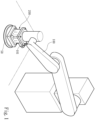
- the present invention provides a grinding package 200 fitted on a robotic arm 100, the grinding package 200 being an application package for the robotic arm 100.
- the grinding package 200 is arranged at the end of the robotic arm 100, and controlled by an electric control module (not shown in the figures) of the robotic arm 100.
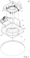
- the grinding package 200 includes a main body 20, a pneumatic motor 30, a bridging part 40 and a grinding tool 50.
- the main body 20 is formed with a first space 21 and a second space 22, the first space 21 and the second space 22 being in the form of a trough, respectively.
- An opening 211 of the first space 21 and an opening 221 of the second space 22 are respectively located on each of two parallel sides (as indicated by 201, 202 in Figs. 3 and 4 ) of the main body 20; that is to say, the opening 211 of the first space 21 and the opening 221 of the second space 22 are directed toward opposed directions. Further, the first space 21 and the second space 22 are located on the same axis.
- the main body 20 is further formed with a communicating hole 23 communicating the first space 21 to the second space 22, a connecting wall 24 provided within the first space 21, an intake channel 25 communicated to the first space 21, and an exhaust channel 26 communicated to the second space 22.
- the hole diameter of the communicating hole 23 is significantly smaller than the aperture of each of the openings 211, 221 of the first space 21 and the second space 22.
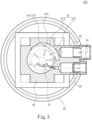
- the connecting wall 24 and the main body 20 are integrally formed, and the connecting wall 24 is placed within the first space 21, such that the first space 21 is separated into an intake region 212 and a working region 213, the intake channel 25 corresponding to the intake region 212, while the exhaust channel 26 corresponding to the working region 213.
- the connecting wall 24 is not provided at the center of the first space 21, in such a way that the intake region 212 is smaller than the working region 213, with the working region 213 approaching a circle more. Further, the height of the connecting wall 24 is not equated with the depth of the first space 21; that is to say, the top end of the connecting wall 24 is not flush with one of the sides 201 of the main body 20.
- the connecting wall 24 may be provided in the form of a circular ring, in which one portion 241 of the connecting wall 24 is placed within the first space 21, while another portion 242 may be provided along an inner wall 214 of the first space 21.
- the connecting wall 24 is further provided thereon with a ventilation hole 243, the ventilation hole 243 communicating the intake region 212 to the working region 213.
- the ventilation hole 243 may be an oblong hole.
- the pneumatic motor 30 includes a motor body 31 provided within the working region 213, and a transmission shaft 32 connected to the motor body 31.
- the motor body 31 is placed into and then located in the working region 213 through the opening 211 of the first space 21, while the transmission shaft 32 is extended from the second space 22 through the communicating hole 23 when the pneumatic motor 30 is put into the working region 213.
- the pneumatic motor 30 is provided with an eccentric block 33 combined with the transmission shaft 32 and located within the second space 22, the eccentric block 33 being joined to the grinding tool 50 while a shaft center 92 of the grinding tool 50 deviating from the center of the transmission shaft 32.
- the bridging part 40 may be provided in the form of a plate.
- the bridging part 40 is combined with the main body 20 and the robotic arm 100.
- the bridging part 40 is mounted on the one side 201, having the opening 211 of the first space 21, of the main body 20, and the bridging part 40 is allowed to close off the first space 21, in such a way that a working gas 91 from the intake channel 25 is only discharged from the exhaust channel 26 through the intake region 212 and the working region 213.
- the bridging part 40 is combined with a joining holder 101 of the robotic arm 100.
- the grinding tool 50 may be a grinding disc or other elements allowed for carrying out grinding. The grinding tool 50, facing the second space 22 and being joined to the transmission shaft 32, is turned by the transmission shaft 32, which is turned by impelling the motor body 31 by the working gas 91.
- the grinding operation is performed on an object (not shown in the figure) in accordance with the movement of the robotic arm 100 after the grinding package 200 and the robotic arm 100 are combined together.
- the exhaust channel 26 is connected to an air extracting module (not shown in the figure) before grinding.
- the air extracting module is started to extract gas within the first space 21 through the exhaust channel 26, so as to form a negative pressure in the first space 21.
- the working gas 91 originally located outside the main body 20 is drawn into the intake region 212 and the working region 213 in turn through the intake channel 25.
- the motor body 31 is impelled by the working gas 91 to turn, and then drive the transmission shaft 32 to rotate, when the working gas 91 enters the working region 213. Further, the grinding tool 50 is driven to rotate so as to perform the grinding operation when the transmission shaft 32 is turned. Next, after impelling the motor body 31, the working gas 91 is expelled from the first space 21 through the exhaust channel 26 toward the air extracting module.
- the main body 20 of the present invention may be formed integrally or composed of several parts in accordance with the practical needs.
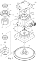
- the main body 20 includes a first part 27 and a second part 28, which may be dismantled selectively.
- the first part 27 is formed with the first space 21, the connecting wall 24, the intake channel 25 and the exhaust channel 26, while the second part 28 is formed thereon with the second space 22 and the communicating hole 23.
- the first part 27 is provided with at least one first threaded hole 271, while the second part 28 is provided with a second threaded hole 281 facing the first threaded hole 271 after the second part 28 and the first part 27 are joined to each other.
- a screwed-connection element 80 is jointly provided in the first threaded hole 271 and the second threaded hole 281, so as to fix the first part 27 to the second part 28.
- the second part 28 is provided with an assembling bump 282 being mounted within the first space 21 and having the communicating hole 23.
- the assembling bump 282 is formed at one side, without the opening 221 of the second space 22, of the second part 28.
- the rising extent of the assembling bump 282 is dependent on the depth of the second space 22, and the shape of the assembling bump 282 is in correspondence with the first space 21.
- the main body 20 is provided with a bearing mounting groove 222 being located within the second space 22 and corresponding to the communicating hole 23.
- the grinding package 200 is provided with a first bearing 60 being located in the bearing mounting groove 222 and allowing the transmission shaft 32 passing therethrough.
- the first bearing 60 is further used for fixing the pneumatic motor 30. More specifically, the hole diameter of the communicating hole 23 should be larger than the diameter of the transmission shaft 32, so as to avoid the effect on work due to excessive friction force generated between the transmission shaft 32 and the communicating hole 23.
- the pneumatic motor 30 may be then supported by the first bearing 60, such that the bottom edge of the motor body 31 is not in contact with the bottom of the first space 21. Additionally, the pneumatic motor 30 is provided with a cover plate 34, which is located at one side, facing the bridging part 40, of the motor body 31.
- the cover plate 34 is provided with a plate body 341 constrained by the main body 20 and the bridging part 40 cooperatively, a through-hole 342 being provided with the plate body 341 and allowing the transmission shaft 32 passing therethrough, and a first annular wall 343 located on the plate body 341 and centered at the through-hole 342, the first annular wall 343 not adjoining the through-hole 342 while surrounding the through-hole 342 at a distance away therefrom.
- the grinding package 200 is provided with a second bearing 61 located within a space encircled by the first annular wall 343 and joined to the transmission shaft 32.
- the pneumatic motor 30 is supported by the second bearing 61 and the first bearing 60 cooperatively, so as to enable stable rotation of the pneumatic motor 30.
- the bridging part 40 is provided with a second annular wall 401 protruding in a direction toward the first space 21 and fastening the first annular wall 343.
- the inner diameter of the second annular wall 401 is equivalent to the outer diameter of the first annular wall 343, and a height 402 of the second annular wall 401 is larger than a height 344 of the first annular wall 343.
- the bridging part 40 in one embodiment is provided with a vent hole 403 located within a region encircled by the second annular wall 401. Convective heat transfer between the second bearing 61, located within the region encircled by the second annular wall 401, and outside air is possible due to the provision of the vent hole 403, so as to avoid heat excessively accumulated on the second bearing 61.
- the main body 20 is provided with at least one third threaded hole 203, while the bridging part 40 is provided with a fourth threaded hole 404 facing the third threaded hole 203 after the bridging part 40 and the main body 20 are joined to each other.
- Another screwed-connection element 81 is jointly provided in the third threaded hole 203 and the fourth threaded hole 404, so as to fix the bridging part 40 to the main body 20.
- the bridging part 40 is provided with a plurality of fifth threaded holes 405 used for connecting the robotic arm 100, respectively.
- a screwed-connection element (not shown in the figures) may be also provided to be joined to each of the plurality of fifth threaded holes 405.
Landscapes
- Engineering & Computer Science (AREA)
- Mechanical Engineering (AREA)
- Robotics (AREA)
- Manipulator (AREA)
Claims (11)
- Auf Roboterarm (100) montiertes Schleifpaket (200), umfassend:einen Hauptkörper (20), der mit einem ersten Raum (21), einem zweiten Raum (22), einem Verbindungsloch (23), das den ersten Raum (21) mit dem zweiten Raum (22) verbindet, einem Einlasskanal (25), einem Auslasskanal (26), einer Öffnung (211) des ersten Raums (21) und einer Öffnung (221) des zweiten Raums (22) ausgebildet ist, die jeweils auf jeder von zwei parallelen Seiten des Hauptkörpers (20) angeordnet sind;einen pneumatischen Motor (30) mit einem Motorkörper (31), der in einem Arbeitsbereich (213) des ersten Raums vorgesehen ist, und einer Übertragungswelle (32), die mit dem Motorkörper (31) verbunden ist, während sie sich aus dem zweiten Raum (22) durch das Verbindungsloch (23) erstreckt; undein Schleifwerkzeug (50), das dem zweiten Raum (22) zugewandt und mit der Übertragungswelle (32) verbunden ist, wobei das Schleifwerkzeug (50) durch die Übertragungswelle (32) gedreht wird, die durch den Antrieb des Motorkörpers (31) durch das Arbeitsgas (91) gedreht wird;wobei das Schleifpaket (200) dadurch gekennzeichnet ist, dass:der Hauptkörper (20) ferner eine Verbindungswand (24) umfasst, die in dem ersten Raum (21) vorgesehen ist, wobei die Verbindungswand (24) den ersten Raum (21) in einen Einlassbereich (212), der mit dem Einlasskanal (25) in Verbindung steht, und den Arbeitsbereich (213), der mit dem Auslasskanal (26) in Verbindung steht, unterteilt, wobei die Verbindungswand (24) nicht in der Mitte des ersten Raums (21) vorgesehen ist und der Ansaugbereich (212) kleiner ist als der Arbeitsbereich (213), und wobei die Verbindungswand (24) mit einer Belüftungsöffnung (243) versehen ist, die den Ansaugbereich (212) mit dem Arbeitsbereich (213) verbindet; unddas Schleifpaket (200) ferner ein Überbrückungsteil (40) umfasst, das mit dem Hauptkörper (20) und dem Roboterarm (100) kombiniert ist, wobei das Überbrückungsteil (40) den ersten Raum (21) verschließt, um ein Arbeitsgas (91) aus dem Einlasskanal (25) zu begrenzen, das aus dem Auslasskanal (26) durch den Einlassbereich (212) und den Arbeitsbereich (213) abgeleitet wird.
- Auf Roboterarm (100) montiertes Schleifpaket (200) nach Anspruch 1, wobei der Hauptkörper (20) einen ersten Teil (27) und einen zweiten Teil (28) umfasst, die selektiv demontiert werden können, wobei der erste Teil (27) mit dem ersten Raum (21), der Verbindungswand (24), dem Einlasskanal (25) und dem Auslasskanal (26) ausgebildet ist, während der zweite Teil (28) mit dem zweiten Raum (22) und dem Verbindungsloch (23) daran ausgebildet ist.
- Auf Roboterarm (100) montiertes Schleifpaket (200) nach Anspruch 2, wobei das erste Teil (27) mit mindestens einem ersten Gewindeloch (271) versehen ist, während das zweite Teil (28) mit einem zweiten Gewindeloch (281) versehen ist, das dem ersten Gewindeloch (271) gegenüberliegt, nachdem das zweite Teil (28) und das erste Teil (27) miteinander verbunden sind.
- Auf Roboterarm (100) montiertes Schleifpaket (200) nach Anspruch 3, wobei das zweite Teil (28) mit einem Montagehöcker (282) versehen ist, der in dem ersten Raum (21) montiert ist und das Verbindungsloch (23) enthält.
- Auf Roboterarm (100) montiertes Schleifpaket (200) nach Anspruch 1, wobei der Hauptkörper (20) mit einer Lagermontagenut (222) versehen ist, die sich in dem zweiten Raum (22) befindet und dem Verbindungsloch (23) entspricht, wobei das Schleifpaket (200) mit einem ersten Lager (60) versehen ist, das sich in der Lagermontagenut (222) befindet und den Durchgang der Übertragungswelle (32) ermöglicht.
- Auf Roboterarm (100) montiertes Schleifpaket (200) nach Anspruch 5, wobei der pneumatische Motor (30) mit einer Abdeckplatte (34) versehen ist, wobei die Abdeckplatte (34) einen Plattenkörper (341) umfasst, der durch den Hauptkörper (20) und das Brückenteil (40) zusammenwirkend eingespannt ist, wobei ein Durchgangsloch (342) mit dem Plattenkörper (341) versehen ist und den Durchgang der Übertragungswelle (32) ermöglicht, und eine erste ringförmige Wand (343), die an dem Plattenkörper (341) angeordnet und an dem Durchgangsloch (342) zentriert ist, wobei das Schleifpaket (200) mit einem zweiten Lager (61) versehen ist, das innerhalb eines Raums angeordnet ist, der von der ersten ringförmigen Wand (343) umgeben und mit der Übertragungswelle (32) verbunden ist.
- Auf Roboterarm (100) montiertes Schleifpaket (200) nach Anspruch 6, wobei das Überbrückungsteil (40) mit einer zweiten ringförmigen Wand (401) versehen ist, die in Richtung des ersten Raums (21) vorsteht und die erste ringförmige Wand (343) befestigt.
- Schleifpaket auf einem Roboterarm nach Anspruch 7, wobei das Brückenteil (40) mit einer Entlüftungsöffnung (403) versehen ist, die sich in einem Bereich befindet, der von der zweiten ringförmigen Wand (401) umgeben ist.
- Auf Roboterarm (100) montiertes Schleifpaket (200) nach Anspruch 1, wobei der Druckluftmotor (30) mit einem Exzenterblock (33) versehen ist, der mit der Übertragungswelle (32) kombiniert und in dem zweiten Raum (22) angeordnet ist, wobei der Exzenterblock (33) mit dem Schleifwerkzeug (50) verbunden ist, während eine Wellenmitte (92) des Schleifwerkzeugs (50) von der Übertragungswelle (32) abweicht.
- Auf Roboterarm (100) montiertes Schleifpaket (200) nach Anspruch 1, wobei der Hauptkörper (20) mit mindestens einem dritten Gewindeloch (203) versehen ist, während das Brückenteil (40) mit einem vierten Gewindeloch (404) versehen ist, das dem dritten Gewindeloch (203) gegenüberliegt, nachdem das Brückenteil (40) und der Hauptkörper (20) miteinander verbunden sind.
- Auf Roboterarm (100) montiertes Schleifpaket (200) nach Anspruch 10, wobei das Brückenteil (40) mit einer Vielzahl von fünften Gewindelöchern (405) versehen ist, die jeweils zur Verbindung mit dem Roboterarm (100) dienen.
Priority Applications (1)
| Application Number | Priority Date | Filing Date | Title |
|---|---|---|---|
| EP18173271.0A EP3569356B1 (de) | 2018-05-18 | 2018-05-18 | Auf roboterarm montiertes schleifpaket |
Applications Claiming Priority (1)
| Application Number | Priority Date | Filing Date | Title |
|---|---|---|---|
| EP18173271.0A EP3569356B1 (de) | 2018-05-18 | 2018-05-18 | Auf roboterarm montiertes schleifpaket |
Publications (2)
| Publication Number | Publication Date |
|---|---|
| EP3569356A1 EP3569356A1 (de) | 2019-11-20 |
| EP3569356B1 true EP3569356B1 (de) | 2023-10-25 |
Family
ID=62245161
Family Applications (1)
| Application Number | Title | Priority Date | Filing Date |
|---|---|---|---|
| EP18173271.0A Active EP3569356B1 (de) | 2018-05-18 | 2018-05-18 | Auf roboterarm montiertes schleifpaket |
Country Status (1)
| Country | Link |
|---|---|
| EP (1) | EP3569356B1 (de) |
Families Citing this family (1)
| Publication number | Priority date | Publication date | Assignee | Title |
|---|---|---|---|---|
| CN114536177B (zh) * | 2022-04-06 | 2024-02-23 | 金溪县金港实业有限公司 | 一种玩具制造用零部件打磨机 |
Family Cites Families (14)
| Publication number | Priority date | Publication date | Assignee | Title |
|---|---|---|---|---|
| JPH0516065A (ja) | 1991-07-12 | 1993-01-26 | Mitsubishi Electric Corp | 研磨装置 |
| JP2000216124A (ja) | 1999-01-26 | 2000-08-04 | Okamoto Machine Tool Works Ltd | 研削装置およびウエハの研削方法 |
| JP2007152502A (ja) | 2005-12-06 | 2007-06-21 | Hokkaido | 自動加工システム |
| JP4838614B2 (ja) | 2006-03-29 | 2011-12-14 | 株式会社岡本工作機械製作所 | 半導体基板の平坦化装置および平坦化方法 |
| US8517799B2 (en) | 2010-12-07 | 2013-08-27 | The Boeing Company | Robotic surface preparation by a random orbital device |
| CN103302563B (zh) * | 2012-03-14 | 2015-11-25 | 富泰华工业(深圳)有限公司 | 打磨装置及使用该打磨装置的机械手 |
| US20130273818A1 (en) * | 2012-04-13 | 2013-10-17 | Hon Hai Precision Industry Co., Ltd. | Manipulator and polishing mechanism thereof |
| CN204195518U (zh) | 2014-10-16 | 2015-03-11 | 中芯国际集成电路制造(北京)有限公司 | 一种研磨装置 |
| JP6730595B2 (ja) | 2016-06-30 | 2020-07-29 | キョーラク株式会社 | クッションパッド及びそれを用いたロボットアーム |
| CN206382997U (zh) * | 2017-01-19 | 2017-08-08 | 东莞市凯保精密机械有限公司 | 偏心式高速大面积打磨机 |
| CN206383026U (zh) * | 2017-01-19 | 2017-08-08 | 东莞市凯保精密机械有限公司 | 偏心式高速小面积打磨机 |
| CN206632836U (zh) | 2017-03-20 | 2017-11-14 | 蓝德工业股份有限公司 | 研磨吸震垫 |
| CN206825119U (zh) * | 2017-04-12 | 2018-01-02 | 深圳市拍档科技有限公司 | 风磨机 |
| CN107738185B (zh) * | 2017-10-20 | 2019-06-07 | 广东天机机器人有限公司 | 打磨头安装机构和三头打磨装置 |
-
2018
- 2018-05-18 EP EP18173271.0A patent/EP3569356B1/de active Active
Also Published As
| Publication number | Publication date |
|---|---|
| EP3569356A1 (de) | 2019-11-20 |
Similar Documents
| Publication | Publication Date | Title |
|---|---|---|
| CN207879571U (zh) | 带电动机的泵 | |
| EP2243962B1 (de) | Motorkühlgebläseeinheit | |
| CN110315482B (zh) | 电动工具 | |
| EP2609844A2 (de) | Motoranordnung für einen Staubsauger | |
| US20170218933A1 (en) | Reciprocating compressor | |
| US11548163B2 (en) | Grinding package fitted on robotic arm | |
| EP3569356B1 (de) | Auf roboterarm montiertes schleifpaket | |
| KR101530568B1 (ko) | 소음 감소를 위한 전동 진공 펌프 | |
| US6942558B2 (en) | Hand-held machine tool | |
| WO2005100815A1 (ja) | 防振装置 | |
| DK2372166T3 (en) | Motor fan unit for a heating, ventilation and / or air conditioning device in a motor vehicle | |
| US20110135523A1 (en) | Sealed compressor with motor standard spacer providing bearing mount | |
| US8662197B2 (en) | Method of assembling a hand machine tool | |
| US20210095664A1 (en) | Cartridge vane pump and pump device | |
| KR20160103820A (ko) | 연료전지 차량용 공기 블로어 | |
| US11780071B2 (en) | Power tool | |
| CN110385637B (zh) | 装配于机械手臂上的研磨套件 | |
| US20210355955A1 (en) | Rotor mounting unit | |
| CN207634328U (zh) | 挡油结构及压缩机 | |
| KR101988446B1 (ko) | 토크 컨버터의 블레이드 자동 조립장치 | |
| KR20070033869A (ko) | 배수펌프 | |
| KR20200068224A (ko) | 토크컨버터 | |
| JPS6240158Y2 (de) | ||
| CN206738235U (zh) | 叶轮和具有其的驱动装置 | |
| JP2024053989A5 (de) |
Legal Events
| Date | Code | Title | Description |
|---|---|---|---|
| PUAI | Public reference made under article 153(3) epc to a published international application that has entered the european phase |
Free format text: ORIGINAL CODE: 0009012 |
|
| STAA | Information on the status of an ep patent application or granted ep patent |
Free format text: STATUS: THE APPLICATION HAS BEEN PUBLISHED |
|
| AK | Designated contracting states |
Kind code of ref document: A1 Designated state(s): AL AT BE BG CH CY CZ DE DK EE ES FI FR GB GR HR HU IE IS IT LI LT LU LV MC MK MT NL NO PL PT RO RS SE SI SK SM TR |
|
| AX | Request for extension of the european patent |
Extension state: BA ME |
|
| STAA | Information on the status of an ep patent application or granted ep patent |
Free format text: STATUS: REQUEST FOR EXAMINATION WAS MADE |
|
| 17P | Request for examination filed |
Effective date: 20200305 |
|
| RBV | Designated contracting states (corrected) |
Designated state(s): AL AT BE BG CH CY CZ DE DK EE ES FI FR GB GR HR HU IE IS IT LI LT LU LV MC MK MT NL NO PL PT RO RS SE SI SK SM TR |
|
| STAA | Information on the status of an ep patent application or granted ep patent |
Free format text: STATUS: EXAMINATION IS IN PROGRESS |
|
| 17Q | First examination report despatched |
Effective date: 20220311 |
|
| GRAP | Despatch of communication of intention to grant a patent |
Free format text: ORIGINAL CODE: EPIDOSNIGR1 |
|
| STAA | Information on the status of an ep patent application or granted ep patent |
Free format text: STATUS: GRANT OF PATENT IS INTENDED |
|
| INTG | Intention to grant announced |
Effective date: 20230526 |
|
| GRAS | Grant fee paid |
Free format text: ORIGINAL CODE: EPIDOSNIGR3 |
|
| GRAA | (expected) grant |
Free format text: ORIGINAL CODE: 0009210 |
|
| STAA | Information on the status of an ep patent application or granted ep patent |
Free format text: STATUS: THE PATENT HAS BEEN GRANTED |
|
| AK | Designated contracting states |
Kind code of ref document: B1 Designated state(s): AL AT BE BG CH CY CZ DE DK EE ES FI FR GB GR HR HU IE IS IT LI LT LU LV MC MK MT NL NO PL PT RO RS SE SI SK SM TR |
|
| REG | Reference to a national code |
Ref country code: GB Ref legal event code: FG4D |
|
| REG | Reference to a national code |
Ref country code: CH Ref legal event code: EP |
|
| REG | Reference to a national code |
Ref country code: DE Ref legal event code: R096 Ref document number: 602018059835 Country of ref document: DE |
|
| REG | Reference to a national code |
Ref country code: IE Ref legal event code: FG4D |
|
| REG | Reference to a national code |
Ref country code: LT Ref legal event code: MG9D |
|
| REG | Reference to a national code |
Ref country code: NL Ref legal event code: MP Effective date: 20231025 |
|
| REG | Reference to a national code |
Ref country code: AT Ref legal event code: MK05 Ref document number: 1624204 Country of ref document: AT Kind code of ref document: T Effective date: 20231025 |
|
| PG25 | Lapsed in a contracting state [announced via postgrant information from national office to epo] |
Ref country code: NL Free format text: LAPSE BECAUSE OF FAILURE TO SUBMIT A TRANSLATION OF THE DESCRIPTION OR TO PAY THE FEE WITHIN THE PRESCRIBED TIME-LIMIT Effective date: 20231025 |
|
| PG25 | Lapsed in a contracting state [announced via postgrant information from national office to epo] |
Ref country code: GR Free format text: LAPSE BECAUSE OF FAILURE TO SUBMIT A TRANSLATION OF THE DESCRIPTION OR TO PAY THE FEE WITHIN THE PRESCRIBED TIME-LIMIT Effective date: 20240126 |
|
| PG25 | Lapsed in a contracting state [announced via postgrant information from national office to epo] |
Ref country code: IS Free format text: LAPSE BECAUSE OF FAILURE TO SUBMIT A TRANSLATION OF THE DESCRIPTION OR TO PAY THE FEE WITHIN THE PRESCRIBED TIME-LIMIT Effective date: 20240225 |
|
| PG25 | Lapsed in a contracting state [announced via postgrant information from national office to epo] |
Ref country code: LT Free format text: LAPSE BECAUSE OF FAILURE TO SUBMIT A TRANSLATION OF THE DESCRIPTION OR TO PAY THE FEE WITHIN THE PRESCRIBED TIME-LIMIT Effective date: 20231025 |
|
| PG25 | Lapsed in a contracting state [announced via postgrant information from national office to epo] |
Ref country code: AT Free format text: LAPSE BECAUSE OF FAILURE TO SUBMIT A TRANSLATION OF THE DESCRIPTION OR TO PAY THE FEE WITHIN THE PRESCRIBED TIME-LIMIT Effective date: 20231025 |
|
| PG25 | Lapsed in a contracting state [announced via postgrant information from national office to epo] |
Ref country code: ES Free format text: LAPSE BECAUSE OF FAILURE TO SUBMIT A TRANSLATION OF THE DESCRIPTION OR TO PAY THE FEE WITHIN THE PRESCRIBED TIME-LIMIT Effective date: 20231025 |
|
| PG25 | Lapsed in a contracting state [announced via postgrant information from national office to epo] |
Ref country code: LT Free format text: LAPSE BECAUSE OF FAILURE TO SUBMIT A TRANSLATION OF THE DESCRIPTION OR TO PAY THE FEE WITHIN THE PRESCRIBED TIME-LIMIT Effective date: 20231025 Ref country code: IS Free format text: LAPSE BECAUSE OF FAILURE TO SUBMIT A TRANSLATION OF THE DESCRIPTION OR TO PAY THE FEE WITHIN THE PRESCRIBED TIME-LIMIT Effective date: 20240225 Ref country code: GR Free format text: LAPSE BECAUSE OF FAILURE TO SUBMIT A TRANSLATION OF THE DESCRIPTION OR TO PAY THE FEE WITHIN THE PRESCRIBED TIME-LIMIT Effective date: 20240126 Ref country code: ES Free format text: LAPSE BECAUSE OF FAILURE TO SUBMIT A TRANSLATION OF THE DESCRIPTION OR TO PAY THE FEE WITHIN THE PRESCRIBED TIME-LIMIT Effective date: 20231025 Ref country code: BG Free format text: LAPSE BECAUSE OF FAILURE TO SUBMIT A TRANSLATION OF THE DESCRIPTION OR TO PAY THE FEE WITHIN THE PRESCRIBED TIME-LIMIT Effective date: 20240125 Ref country code: AT Free format text: LAPSE BECAUSE OF FAILURE TO SUBMIT A TRANSLATION OF THE DESCRIPTION OR TO PAY THE FEE WITHIN THE PRESCRIBED TIME-LIMIT Effective date: 20231025 Ref country code: PT Free format text: LAPSE BECAUSE OF FAILURE TO SUBMIT A TRANSLATION OF THE DESCRIPTION OR TO PAY THE FEE WITHIN THE PRESCRIBED TIME-LIMIT Effective date: 20240226 |
|
| PG25 | Lapsed in a contracting state [announced via postgrant information from national office to epo] |
Ref country code: SE Free format text: LAPSE BECAUSE OF FAILURE TO SUBMIT A TRANSLATION OF THE DESCRIPTION OR TO PAY THE FEE WITHIN THE PRESCRIBED TIME-LIMIT Effective date: 20231025 Ref country code: RS Free format text: LAPSE BECAUSE OF FAILURE TO SUBMIT A TRANSLATION OF THE DESCRIPTION OR TO PAY THE FEE WITHIN THE PRESCRIBED TIME-LIMIT Effective date: 20231025 Ref country code: PL Free format text: LAPSE BECAUSE OF FAILURE TO SUBMIT A TRANSLATION OF THE DESCRIPTION OR TO PAY THE FEE WITHIN THE PRESCRIBED TIME-LIMIT Effective date: 20231025 Ref country code: NO Free format text: LAPSE BECAUSE OF FAILURE TO SUBMIT A TRANSLATION OF THE DESCRIPTION OR TO PAY THE FEE WITHIN THE PRESCRIBED TIME-LIMIT Effective date: 20240125 Ref country code: LV Free format text: LAPSE BECAUSE OF FAILURE TO SUBMIT A TRANSLATION OF THE DESCRIPTION OR TO PAY THE FEE WITHIN THE PRESCRIBED TIME-LIMIT Effective date: 20231025 Ref country code: HR Free format text: LAPSE BECAUSE OF FAILURE TO SUBMIT A TRANSLATION OF THE DESCRIPTION OR TO PAY THE FEE WITHIN THE PRESCRIBED TIME-LIMIT Effective date: 20231025 |
|
| PG25 | Lapsed in a contracting state [announced via postgrant information from national office to epo] |
Ref country code: DK Free format text: LAPSE BECAUSE OF FAILURE TO SUBMIT A TRANSLATION OF THE DESCRIPTION OR TO PAY THE FEE WITHIN THE PRESCRIBED TIME-LIMIT Effective date: 20231025 |
|
| PG25 | Lapsed in a contracting state [announced via postgrant information from national office to epo] |
Ref country code: CZ Free format text: LAPSE BECAUSE OF FAILURE TO SUBMIT A TRANSLATION OF THE DESCRIPTION OR TO PAY THE FEE WITHIN THE PRESCRIBED TIME-LIMIT Effective date: 20231025 |
|
| REG | Reference to a national code |
Ref country code: DE Ref legal event code: R097 Ref document number: 602018059835 Country of ref document: DE |
|
| PG25 | Lapsed in a contracting state [announced via postgrant information from national office to epo] |
Ref country code: SK Free format text: LAPSE BECAUSE OF FAILURE TO SUBMIT A TRANSLATION OF THE DESCRIPTION OR TO PAY THE FEE WITHIN THE PRESCRIBED TIME-LIMIT Effective date: 20231025 |
|
| PG25 | Lapsed in a contracting state [announced via postgrant information from national office to epo] |
Ref country code: SM Free format text: LAPSE BECAUSE OF FAILURE TO SUBMIT A TRANSLATION OF THE DESCRIPTION OR TO PAY THE FEE WITHIN THE PRESCRIBED TIME-LIMIT Effective date: 20231025 Ref country code: SK Free format text: LAPSE BECAUSE OF FAILURE TO SUBMIT A TRANSLATION OF THE DESCRIPTION OR TO PAY THE FEE WITHIN THE PRESCRIBED TIME-LIMIT Effective date: 20231025 Ref country code: RO Free format text: LAPSE BECAUSE OF FAILURE TO SUBMIT A TRANSLATION OF THE DESCRIPTION OR TO PAY THE FEE WITHIN THE PRESCRIBED TIME-LIMIT Effective date: 20231025 Ref country code: EE Free format text: LAPSE BECAUSE OF FAILURE TO SUBMIT A TRANSLATION OF THE DESCRIPTION OR TO PAY THE FEE WITHIN THE PRESCRIBED TIME-LIMIT Effective date: 20231025 Ref country code: DK Free format text: LAPSE BECAUSE OF FAILURE TO SUBMIT A TRANSLATION OF THE DESCRIPTION OR TO PAY THE FEE WITHIN THE PRESCRIBED TIME-LIMIT Effective date: 20231025 Ref country code: CZ Free format text: LAPSE BECAUSE OF FAILURE TO SUBMIT A TRANSLATION OF THE DESCRIPTION OR TO PAY THE FEE WITHIN THE PRESCRIBED TIME-LIMIT Effective date: 20231025 |
|
| PLBE | No opposition filed within time limit |
Free format text: ORIGINAL CODE: 0009261 |
|
| STAA | Information on the status of an ep patent application or granted ep patent |
Free format text: STATUS: NO OPPOSITION FILED WITHIN TIME LIMIT |
|
| 26N | No opposition filed |
Effective date: 20240726 |
|
| PG25 | Lapsed in a contracting state [announced via postgrant information from national office to epo] |
Ref country code: SI Free format text: LAPSE BECAUSE OF FAILURE TO SUBMIT A TRANSLATION OF THE DESCRIPTION OR TO PAY THE FEE WITHIN THE PRESCRIBED TIME-LIMIT Effective date: 20231025 |
|
| PG25 | Lapsed in a contracting state [announced via postgrant information from national office to epo] |
Ref country code: SI Free format text: LAPSE BECAUSE OF FAILURE TO SUBMIT A TRANSLATION OF THE DESCRIPTION OR TO PAY THE FEE WITHIN THE PRESCRIBED TIME-LIMIT Effective date: 20231025 |
|
| REG | Reference to a national code |
Ref country code: CH Ref legal event code: PL |
|
| PG25 | Lapsed in a contracting state [announced via postgrant information from national office to epo] |
Ref country code: MC Free format text: LAPSE BECAUSE OF FAILURE TO SUBMIT A TRANSLATION OF THE DESCRIPTION OR TO PAY THE FEE WITHIN THE PRESCRIBED TIME-LIMIT Effective date: 20231025 |
|
| PG25 | Lapsed in a contracting state [announced via postgrant information from national office to epo] |
Ref country code: LU Free format text: LAPSE BECAUSE OF NON-PAYMENT OF DUE FEES Effective date: 20240518 |
|
| PG25 | Lapsed in a contracting state [announced via postgrant information from national office to epo] |
Ref country code: MC Free format text: LAPSE BECAUSE OF FAILURE TO SUBMIT A TRANSLATION OF THE DESCRIPTION OR TO PAY THE FEE WITHIN THE PRESCRIBED TIME-LIMIT Effective date: 20231025 Ref country code: LU Free format text: LAPSE BECAUSE OF NON-PAYMENT OF DUE FEES Effective date: 20240518 Ref country code: CH Free format text: LAPSE BECAUSE OF NON-PAYMENT OF DUE FEES Effective date: 20240531 |
|
| REG | Reference to a national code |
Ref country code: BE Ref legal event code: MM Effective date: 20240531 |
|
| PG25 | Lapsed in a contracting state [announced via postgrant information from national office to epo] |
Ref country code: IE Free format text: LAPSE BECAUSE OF NON-PAYMENT OF DUE FEES Effective date: 20240518 |
|
| PG25 | Lapsed in a contracting state [announced via postgrant information from national office to epo] |
Ref country code: BE Free format text: LAPSE BECAUSE OF NON-PAYMENT OF DUE FEES Effective date: 20240531 |
|
| PGFP | Annual fee paid to national office [announced via postgrant information from national office to epo] |
Ref country code: DE Payment date: 20250530 Year of fee payment: 8 |
|
| PGFP | Annual fee paid to national office [announced via postgrant information from national office to epo] |
Ref country code: GB Payment date: 20250530 Year of fee payment: 8 |
|
| PGFP | Annual fee paid to national office [announced via postgrant information from national office to epo] |
Ref country code: IT Payment date: 20250530 Year of fee payment: 8 |
|
| PGFP | Annual fee paid to national office [announced via postgrant information from national office to epo] |
Ref country code: FR Payment date: 20250530 Year of fee payment: 8 |
|
| PG25 | Lapsed in a contracting state [announced via postgrant information from national office to epo] |
Ref country code: CY Free format text: LAPSE BECAUSE OF FAILURE TO SUBMIT A TRANSLATION OF THE DESCRIPTION OR TO PAY THE FEE WITHIN THE PRESCRIBED TIME-LIMIT; INVALID AB INITIO Effective date: 20180518 |
|
| PG25 | Lapsed in a contracting state [announced via postgrant information from national office to epo] |
Ref country code: HU Free format text: LAPSE BECAUSE OF FAILURE TO SUBMIT A TRANSLATION OF THE DESCRIPTION OR TO PAY THE FEE WITHIN THE PRESCRIBED TIME-LIMIT; INVALID AB INITIO Effective date: 20180518 |
|
| PG25 | Lapsed in a contracting state [announced via postgrant information from national office to epo] |
Ref country code: FI Free format text: LAPSE BECAUSE OF FAILURE TO SUBMIT A TRANSLATION OF THE DESCRIPTION OR TO PAY THE FEE WITHIN THE PRESCRIBED TIME-LIMIT Effective date: 20231025 |