EP3568977B1 - Behälterinspektionssystem mit hellfeld-beleuchtung - Google Patents
Behälterinspektionssystem mit hellfeld-beleuchtung Download PDFInfo
- Publication number
- EP3568977B1 EP3568977B1 EP18738516.6A EP18738516A EP3568977B1 EP 3568977 B1 EP3568977 B1 EP 3568977B1 EP 18738516 A EP18738516 A EP 18738516A EP 3568977 B1 EP3568977 B1 EP 3568977B1
- Authority
- EP
- European Patent Office
- Prior art keywords
- container
- image
- inspection
- camera
- sidewall
- Prior art date
- Legal status (The legal status is an assumption and is not a legal conclusion. Google has not performed a legal analysis and makes no representation as to the accuracy of the status listed.)
- Active
Links
Images


Classifications
-
- G—PHYSICS
- G01—MEASURING; TESTING
- G01N—INVESTIGATING OR ANALYSING MATERIALS BY DETERMINING THEIR CHEMICAL OR PHYSICAL PROPERTIES
- G01N21/00—Investigating or analysing materials by the use of optical means, i.e. using sub-millimetre waves, infrared, visible or ultraviolet light
- G01N21/84—Systems specially adapted for particular applications
- G01N21/88—Investigating the presence of flaws or contamination
- G01N21/90—Investigating the presence of flaws or contamination in a container or its contents
-
- G—PHYSICS
- G01—MEASURING; TESTING
- G01N—INVESTIGATING OR ANALYSING MATERIALS BY DETERMINING THEIR CHEMICAL OR PHYSICAL PROPERTIES
- G01N21/00—Investigating or analysing materials by the use of optical means, i.e. using sub-millimetre waves, infrared, visible or ultraviolet light
- G01N21/17—Systems in which incident light is modified in accordance with the properties of the material investigated
- G01N21/25—Colour; Spectral properties, i.e. comparison of effect of material on the light at two or more different wavelengths or wavelength bands
- G01N21/251—Colorimeters; Construction thereof
-
- G—PHYSICS
- G01—MEASURING; TESTING
- G01N—INVESTIGATING OR ANALYSING MATERIALS BY DETERMINING THEIR CHEMICAL OR PHYSICAL PROPERTIES
- G01N21/00—Investigating or analysing materials by the use of optical means, i.e. using sub-millimetre waves, infrared, visible or ultraviolet light
- G01N21/84—Systems specially adapted for particular applications
- G01N21/88—Investigating the presence of flaws or contamination
- G01N21/8806—Specially adapted optical and illumination features
-
- G—PHYSICS
- G01—MEASURING; TESTING
- G01N—INVESTIGATING OR ANALYSING MATERIALS BY DETERMINING THEIR CHEMICAL OR PHYSICAL PROPERTIES
- G01N21/00—Investigating or analysing materials by the use of optical means, i.e. using sub-millimetre waves, infrared, visible or ultraviolet light
- G01N21/84—Systems specially adapted for particular applications
- G01N21/88—Investigating the presence of flaws or contamination
- G01N21/90—Investigating the presence of flaws or contamination in a container or its contents
- G01N21/9036—Investigating the presence of flaws or contamination in a container or its contents using arrays of emitters or receivers
-
- G—PHYSICS
- G01—MEASURING; TESTING
- G01N—INVESTIGATING OR ANALYSING MATERIALS BY DETERMINING THEIR CHEMICAL OR PHYSICAL PROPERTIES
- G01N21/00—Investigating or analysing materials by the use of optical means, i.e. using sub-millimetre waves, infrared, visible or ultraviolet light
- G01N21/84—Systems specially adapted for particular applications
- G01N21/88—Investigating the presence of flaws or contamination
- G01N21/90—Investigating the presence of flaws or contamination in a container or its contents
- G01N21/909—Investigating the presence of flaws or contamination in a container or its contents in opaque containers or opaque container parts, e.g. cans, tins, caps, labels
-
- G—PHYSICS
- G01—MEASURING; TESTING
- G01N—INVESTIGATING OR ANALYSING MATERIALS BY DETERMINING THEIR CHEMICAL OR PHYSICAL PROPERTIES
- G01N21/00—Investigating or analysing materials by the use of optical means, i.e. using sub-millimetre waves, infrared, visible or ultraviolet light
- G01N21/84—Systems specially adapted for particular applications
- G01N21/88—Investigating the presence of flaws or contamination
- G01N21/95—Investigating the presence of flaws or contamination characterised by the material or shape of the object to be examined
- G01N21/952—Inspecting the exterior surface of cylindrical bodies or wires
-
- G—PHYSICS
- G06—COMPUTING OR CALCULATING; COUNTING
- G06T—IMAGE DATA PROCESSING OR GENERATION, IN GENERAL
- G06T7/00—Image analysis
- G06T7/0002—Inspection of images, e.g. flaw detection
- G06T7/0004—Industrial image inspection
- G06T7/001—Industrial image inspection using an image reference approach
-
- G—PHYSICS
- G06—COMPUTING OR CALCULATING; COUNTING
- G06T—IMAGE DATA PROCESSING OR GENERATION, IN GENERAL
- G06T7/00—Image analysis
- G06T7/90—Determination of colour characteristics
-
- H—ELECTRICITY
- H04—ELECTRIC COMMUNICATION TECHNIQUE
- H04N—PICTORIAL COMMUNICATION, e.g. TELEVISION
- H04N23/00—Cameras or camera modules comprising electronic image sensors; Control thereof
- H04N23/56—Cameras or camera modules comprising electronic image sensors; Control thereof provided with illuminating means
-
- H—ELECTRICITY
- H04—ELECTRIC COMMUNICATION TECHNIQUE
- H04N—PICTORIAL COMMUNICATION, e.g. TELEVISION
- H04N23/00—Cameras or camera modules comprising electronic image sensors; Control thereof
- H04N23/90—Arrangement of cameras or camera modules, e.g. multiple cameras in TV studios or sports stadiums
-
- H—ELECTRICITY
- H04—ELECTRIC COMMUNICATION TECHNIQUE
- H04N—PICTORIAL COMMUNICATION, e.g. TELEVISION
- H04N23/00—Cameras or camera modules comprising electronic image sensors; Control thereof
- H04N23/95—Computational photography systems, e.g. light-field imaging systems
- H04N23/957—Light-field or plenoptic cameras or camera modules
-
- H—ELECTRICITY
- H04—ELECTRIC COMMUNICATION TECHNIQUE
- H04N—PICTORIAL COMMUNICATION, e.g. TELEVISION
- H04N7/00—Television systems
- H04N7/18—Closed-circuit television [CCTV] systems, i.e. systems in which the video signal is not broadcast
- H04N7/181—Closed-circuit television [CCTV] systems, i.e. systems in which the video signal is not broadcast for receiving images from a plurality of remote sources
-
- G—PHYSICS
- G01—MEASURING; TESTING
- G01N—INVESTIGATING OR ANALYSING MATERIALS BY DETERMINING THEIR CHEMICAL OR PHYSICAL PROPERTIES
- G01N21/00—Investigating or analysing materials by the use of optical means, i.e. using sub-millimetre waves, infrared, visible or ultraviolet light
- G01N21/84—Systems specially adapted for particular applications
- G01N21/88—Investigating the presence of flaws or contamination
- G01N21/8806—Specially adapted optical and illumination features
- G01N2021/8812—Diffuse illumination, e.g. "sky"
- G01N2021/8816—Diffuse illumination, e.g. "sky" by using multiple sources, e.g. LEDs
-
- G—PHYSICS
- G01—MEASURING; TESTING
- G01N—INVESTIGATING OR ANALYSING MATERIALS BY DETERMINING THEIR CHEMICAL OR PHYSICAL PROPERTIES
- G01N21/00—Investigating or analysing materials by the use of optical means, i.e. using sub-millimetre waves, infrared, visible or ultraviolet light
- G01N21/84—Systems specially adapted for particular applications
- G01N21/88—Investigating the presence of flaws or contamination
- G01N21/8806—Specially adapted optical and illumination features
- G01N2021/8812—Diffuse illumination, e.g. "sky"
- G01N2021/8819—Diffuse illumination, e.g. "sky" by using retroreflecting screen
-
- G—PHYSICS
- G01—MEASURING; TESTING
- G01N—INVESTIGATING OR ANALYSING MATERIALS BY DETERMINING THEIR CHEMICAL OR PHYSICAL PROPERTIES
- G01N21/00—Investigating or analysing materials by the use of optical means, i.e. using sub-millimetre waves, infrared, visible or ultraviolet light
- G01N21/84—Systems specially adapted for particular applications
- G01N21/88—Investigating the presence of flaws or contamination
- G01N21/8806—Specially adapted optical and illumination features
- G01N2021/8822—Dark field detection
-
- G—PHYSICS
- G01—MEASURING; TESTING
- G01N—INVESTIGATING OR ANALYSING MATERIALS BY DETERMINING THEIR CHEMICAL OR PHYSICAL PROPERTIES
- G01N2201/00—Features of devices classified in G01N21/00
- G01N2201/06—Illumination; Optics
- G01N2201/062—LED's
-
- G—PHYSICS
- G01—MEASURING; TESTING
- G01N—INVESTIGATING OR ANALYSING MATERIALS BY DETERMINING THEIR CHEMICAL OR PHYSICAL PROPERTIES
- G01N2201/00—Features of devices classified in G01N21/00
- G01N2201/12—Circuits of general importance; Signal processing
-
- G—PHYSICS
- G06—COMPUTING OR CALCULATING; COUNTING
- G06T—IMAGE DATA PROCESSING OR GENERATION, IN GENERAL
- G06T2207/00—Indexing scheme for image analysis or image enhancement
- G06T2207/10—Image acquisition modality
- G06T2207/10024—Color image
-
- G—PHYSICS
- G06—COMPUTING OR CALCULATING; COUNTING
- G06T—IMAGE DATA PROCESSING OR GENERATION, IN GENERAL
- G06T2207/00—Indexing scheme for image analysis or image enhancement
- G06T2207/10—Image acquisition modality
- G06T2207/10141—Special mode during image acquisition
- G06T2207/10152—Varying illumination
-
- G—PHYSICS
- G06—COMPUTING OR CALCULATING; COUNTING
- G06T—IMAGE DATA PROCESSING OR GENERATION, IN GENERAL
- G06T2207/00—Indexing scheme for image analysis or image enhancement
- G06T2207/30—Subject of image; Context of image processing
- G06T2207/30108—Industrial image inspection
- G06T2207/30116—Casting
-
- G—PHYSICS
- G06—COMPUTING OR CALCULATING; COUNTING
- G06T—IMAGE DATA PROCESSING OR GENERATION, IN GENERAL
- G06T2207/00—Indexing scheme for image analysis or image enhancement
- G06T2207/30—Subject of image; Context of image processing
- G06T2207/30108—Industrial image inspection
- G06T2207/30144—Printing quality
Definitions
- Production plants for manufacturing containers can produce a very large number of containers, with sophisticated (multicolor) decoration thereon, in a relatively short amount of time. For instance, a conventional decorator in a container production plant can decorate 2,000 containers per minute.
- Container decorations have intrinsic value, as consumers tend to attach perceptions of quality to a product based upon the design on the container that holds the product.
- a known process for container inspection is tasking an operator at the plant with periodically pulling containers from a conveyor for visual inspection. For instance, every so often (e.g., every 15 minutes), the operator may be tasked with pulling a small number of containers from the conveyor and visually inspecting the containers to ensure that the exterior surfaces of the containers are free of readily apparent defects (e.g., to ensure that proper colors are applied to the exterior surfaces of the containers, to ensure that the exterior surfaces of the containers are free of smears, etc.).
- thousands of defective containers may be manufactured prior to the operator noticing a defect on the exterior surface of one or more of the sampled containers. In practice, these (completed) containers must be scrapped, resulting in significant cost to the container manufacturer.
- a container inspection system as defined in claim 1, that is configured to ascertain whether a container being transported on a conveyor includes a defect on an exterior surface of a sidewall of the container.
- the container inspection system can detect defects that may occur in a design or label on an exterior surface of the container, such as an improper color being printed on the exterior surface of the container (e.g., a color shade is incorrect), smearing, and so forth, such that the design or label does not appear as desired.
- the container inspection system can detect various defects on exterior surfaces of containers, including physical defects (e.g., scratches, dents, etc.) or voids in decorations (e.g., where a portion of a container should be covered by ink but instead is bare metal).
- Described herein are features pertaining to identifying defects in a sidewall of a container, wherein an exterior surface of the sidewall of the container is at least somewhat reflective. Further, when reference is made to detecting defects in the sidewall of the container, such action is also intended to encompass detecting defects in labels applied to the sidewall of the container (such as a shrink-wrap label or paper label).
- the container may be decorated with ink and/or comprise a highly reflective material (such as bare metal).
- the system further comprises a computing system 124 that receives the signal output by the sensor 122.
- the computing system 124 can receive the signal from the sensor 122 by way of a wireless or wireline connection.
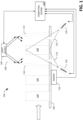
- the system further comprises a light source 126 that is configured to cause a sidewall of the first container 106 to be illuminated when it is within the inspection region of the inspection dome 108.
- the light source 126 can include an array of light emitting diodes (LEDs), wherein each LED emits white light. More particularly, the light source 126 diffusely emits light, resulting in a relatively uniform light field throughout the interior of the inspection dome 108 (such that the first container 106 is illuminated by way of light field illumination, rather than dark field illumination).
- the light source 126 diffusely emits light, the light reflects off the reflective interior wall of the inspection dome 108, resulting in a relatively uniform light field throughout the inspection dome 108 (e.g., light is incident upon the exterior surface of the sidewall of the first container 106 at various angles due to the light being diffusely emitted from the light source 126 and "bouncing around" in the inspection dome 108).
- the computing system 124 controls the light source 126, such that the light source 126 strobes responsive to the computing system 124 ascertaining that the first container 106 is in the inspection region in the inspection dome 108.
- Fig. 1 depicts the first container 106 as being the only container in the inspection dome 108
- the computing system 124 can be configured to process images captured by the cameras 118 and 120 to remove regions of the images that include unwanted reflections and replace such regions with regions of images captured by other cameras, where the replacement regions do not include unwanted reflections (and where the replacement regions map to the same physical locations on the exterior sidewall of the first container 106 as the replaced regions).
- FIG. 2 an overhead view of the exemplary light field illumination container inspection 100 is illustrated, wherein the first container 106 is in the inspection region of the inspection dome 108.
- a first reflection 202 of the first camera aperture 114 is captured in an image of the exterior sidewall of the first container 106 taken by the first camera 118.
- a second reflection 204 of the first camera aperture 114 is captured in an image of the exterior sidewall of the first container 106 taken by the second camera 120.
- the reflections 202 and 204 in the different images, map to different physical locations on the exterior surface of the first container 106 (due to the cameras capturing the images of the first container 106 from different perspectives). Moreover, the reflections 202 and 204 appear at different locations in the images captured by the cameras 118 and 120. It can also be ascertained that since relative positions between the cameras 118 and 120 and the apertures 110-116 (as well as adjacent containers, if any) are known, regions in images captured by the cameras 118-120 that include reflections can be known a priori.
- the computing system 124 receives the image captured by the first camera 118 and the image captured by the second camera 120 and determines whether the exterior surface of the sidewall of the container 106 includes a defect based upon the images. As will be described in greater detail below, the computing system 124 can process each image, such that the portion of the exterior surface of the sidewall of the first container 106 captured in each image is "flattened". Subsequently, the computing system 124 can define, in a first image of the exterior surface of the sidewall of the first container 106 (captured by the first camera 118), a first region that includes the first reflection 202 (and other regions that include other reflections that may be captured in the first image).
- the computing system 124 can replace the first region in the first image with a second region in a second image of the exterior surface of the sidewall of the first container (captured by the second camera 120), where the first region and the second region map to a same physical region of the exterior surface of the sidewall of the first container 106. It can be ascertained that the second region of the second image does not depict the reflections found in the first region of the first image, since the first and second images are captured by cameras at different positions relative to the first container 106. This process can be repeated for every region in the first image that depict reflections, such that these regions are replaced with regions of other images that do not depict the reflections.
- regions in the images can be identified before the images are captured based upon geometries of the container inspection system 100.
- regions in the first image (captured by the first camera 118) can be replaced with regions of several images captured by several different cameras (including the second camera 120).
- the first image becomes a reflection-free image of the sidewall of the first container 106.
- the computing system 124 performs this process for each image captured by each camera, thereby creating several reflection-free images.
- the computing system 124 can optionally stitch the reflection-free images together, thereby creating an image of the first container 106 as if the first container 106 were unwrapped (referred to as an unwrapped image).
- the computing system 124. can then align the unwrapped image of the first container 106 with a statistical model that represents a container that is free of defects.
- a defect may include an improper color hue, a bare metal defect, etc.
- colorimetric analysis can be undertaken on the resultant unwrapped image. Therefore, in addition to identifying physical defects, the computing system 124 can identify color-related defects on the exterior sidewall of the first container 106.
- the computing system 124 can output a signal that causes, for instance, the first container 106 to be removed from the conveyor 102, such that the first container 106 is prevented from being populated with content and further prevented from being made available to a consumer.
- the inspection system 100 may include multiple cameras (and respective camera apertures in the inspection dome 108) positioned around the inspection dome 108.
- the system 100 can include six cameras (and six respective camera apertures) directed radially inwards towards the center axis of the inspection dome 108.
- the six cameras can be symmetrically arranged about the center axis.
- the six cameras each capture images of the first container 106 when the center axis of the first container 106 is aligned with the center axis of the inspection dome 108, which is also when the first container 106 is illuminated by way of light field illumination.
- the captured images 1) each depict portions of the sidewall of the first container 106; and 2) may include reflections of conveyor apertures or camera apertures.
- the inspection system 100 can be configured to perform both light field and dark field inspection of containers.
- the inspection system 100 can include a second light source (not shown), where the second light source can be configured to direct collimated light towards the exterior surface of the sidewall of the first container 106 (at a steep angle relative to the exterior surface of the sidewall of the first container 106).
- the second light source can be used to illuminate the exterior surface of the sidewall of the container 106, the exterior surface of the sidewall of the container 106 is illuminated by way of dark field illumination.
- the cameras 118 and 120 can each capture two images: a first image when the exterior surface of the sidewall of the first container 106 is illuminated by way of light field illumination, and a second image when the exterior surface of the sidewall of the first container 106 is illuminated by way of dark field illumination. These images can be captured closely in time (within milliseconds), wherein the container 106 is in the inspection region of the inspection dome 108 for both images.
- separate sets of cameras can be used to capture images when the container is illuminated using light field illumination and dark field illumination, respectively (where, optionally, a set of cameras used with light field illumination includes more cameras than a set of cameras used with dark field illumination).
- images of the sidewall of the first container 106 taken under dark field illumination are well-suited for use when identifying spatial defects, three-dimensional defects (e.g., dents, scuffs, contamination, etc.), and subtle color shifts in opaque inks on the first container 106.
- the computing system 124 can be further configured to identify these defects when the first container 106 is illuminated under dark field illumination using conventional approaches.
- the container inspection system 300 comprises six cameras 302-312, arranged around the exterior of the inspection dome 108, and configured to simultaneously capture images of the container 106 when the container is illuminated in the inspection dome 108. While not shown, it is understood that the inspection dome 108 in this example includes entry and exit apertures, as well as six camera apertures. While examples set forth herein refer to the inspection system including two cameras, it has been found to be beneficial for the inspection system to have six cameras to allow for sufficient overlap between regions of the container 106 captured in images generated by adjacent cameras in the inspection system 300.
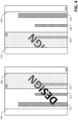
- exemplary images 402-404 captured, for instance, by the first camera 118 and the second camera 120 when the first container 106 is in the inspection region of the inspection dome 108 are illustrated.
- the first image 402, captured by the first camera 118 depicts a portion of the exterior surface of the sidewall of the first container 106, where lines 406 and 408 depict boundaries of the first container 106 in the first image 402.
- the first image 402 depicts the word "DESIGN" printed on the exterior surface of the sidewall of the first container 106.
- the computing system 124 can identify a band 410 in the first image 402, where the band 410 includes a reflection of the entry aperture 110 visible in the first image 402.
- the computing system 124 can identify bands 412 and 414 in the first image 402, where the bands 412-414 include reflections of the first camera aperture 114 and the second camera aperture 116, respectively, which are visible in the first image 402.
- the second image 404 depicts another portion of the exterior surface of the sidewall of the first container 106, where lines 416-418 depict boundaries of the first container 106 in the second image 404.
- the first image 402 includes a first region 420 that depicts a portion of the sidewall of the first container 106
- the second image 404 includes a second region 422 that depicts the same portion of the sidewall of the first container 106.
- the regions 420 and 422 map to a same physical region of the exterior sidewall of the first container 106 (due to the cameras 118 and 120 having overlapping fields of view).
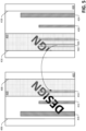
- the second image 404 includes a portion of the word "DESIGN". Similar to what has been described above with respect to the first image 402, the computing system 124 can identify bands 424-428 in the second image 404, where the bands 424-428 comprise reflections of exit aperture 112 and other camera apertures.
- the second image 404 can include a band 502, wherein the band 502 is free of reflections. Further, the band 502 corresponds to the same physical region of the exterior sidewall of the first container 106 as the band 414 of the first image 402 (which depicts a reflection).
- the computing system 124 can be programmed to identify that the band 414 of the first image 402 can be replaced with the band 502 of the second image 404 based upon known geometries of the inspection system 100, and can further be programmed to replace the band 414 in the first image 402 with the band 502 in the second image.
- the bands 410 and 412 in the first image can be replaced with bands from other images that are free of reflections, in a manner similar to what has been described above with respect to the band 502 from the second image 404 replacing the band 414 in the first image 402.
- Fig. 5 is set forth to illustrate replacement of a band in one image with a band in another image
- the computing system 124 can have knowledge of locations of the bands 410-414 in the first image 402.
- the computing system 124 instead of replacing the bands 410-414, can filter the bands 410-414 from the first image 402 when determining whether there is a defect in the sidewall of the first container 106. More specifically, the computing system 124 can receive the first image 402 from the first camera 118, perform image processing on the first image 118 to "flatten" the first container 106 in the first image 402 (such that the first image appears as shown in Fig.
- the computing system 124 can filter the bands 410-414 from the first image 402, such that pixels in the bands 410-414 are not considered by the computing system 124 when determining whether the exterior surface of the sidewall of the first container 106 is defective.
- This process can be repeated for each image captured by cameras of the container inspection system 100, thus, even though a band that includes a region of the exterior surface of the sidewall of the first container 106 is filtered in one of the images, due to the overlapping fields of view of the cameras of the system 100, a portion of a second image that depicts a same region of the exterior sidewall of the first container 106 will be considered by the computing system 124 when determining whether the exterior sidewall of the first container 106 is defective.
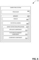
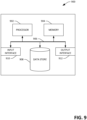
- the computing system 124 includes a processor 602 and memory 604.
- the memory has images 606 (generated by the cameras of the inspection system 100) loaded therein.
- the images 606 can comprise: 1) the image 402 captured by the first camera 118; and 2) the image 404 captured by the second camera 120, wherein the images are of the exterior surface of the sidewall of the first container 106 when illuminated by way of light field illumination.
- the memory has a statistical model 608 of a defect-free (and unwrapped) container loaded therein.
- the statistical model can comprise a plurality of pixels, and each pixel can have a distribution assigned thereto, where the distribution is indicative of values of the pixel that correspond to a non-defective container.
- the computing system 124 generates the statistical model 608 based upon images of a number of non-defective containers.
- the system 100 prior to inspecting containers, processes a preselected number of non-defective containers.
- the first camera 118 and the second camera 120 capture images of non-defective containers as such containers pass through the inspection dome 108 of the system 100.
- the computing system 124 forms unwrapped images of these containers as described above, and aligns the unwrapped images with one another.
- the computing system 124 can perform any suitable image processing technique to create a pixel-by-pixel correspondence between unwrapped images, where each pixel has a value assigned thereto, with the value being indicative of color of the pixel.
- the computing system 124 can form the statistical model 608 of a container that is to be inspected, where the statistical model includes, for instance, a distribution of values for each pixel.
- the computing system 124 can receive a template spectrophotometer measurement of a graphic and/or text that is on the exterior surface of the sidewall of the first container 106. The computing system 124 can generate the statistical model 608 based upon the spectrophotometer measurement.
- the memory 604 additionally has a defect detection application 610 loaded therein.
- the defect detection application 610 is generally configured to ascertain whether the exterior surface of the sidewall of the first container 106 has a defect therein based upon the images 606 and the statistical model 608.
- the defect detection application 610 can be configured to identify color defects, scratches, or voids in decorations (particularly decorations with ink of dark colors).
- the defect detection application 610 comprises a replacer component 612, which is configured to process each image, such that the portion of the exterior sidewall of the container captured in each image is "flattened".
- the replacer component 612 is configured to identify, for each image in the images, bands that depict reflections in the exterior surface of the sidewall of the first container 106 and bands that do not depict reflections in the exterior surface of the sidewall of the first container 106 (but that can be used to replace "reflective" bands from other images). Since the geometries of the system 100 are static (with the possible exception of distance between containers being somewhat variable), the locations of the bands in images captured by cameras of the inspection system 100 are likewise static. Responsive to identifying these bands, the replacer component 612 replaces bands in images that depicts reflections with corresponding bands from other images (as illustrated in Fig. 4 ), thereby forming several "reflection-free" images.
- the defect detection application 610 additionally comprises a comparer component 616.
- the comparer component 616 is configured to compare reflection-free images of a sidewall of a container (partial or complete) with the statistical model 608.
- the comparer component 616 can compare the value of each pixel in the reflection-free image with the corresponding statistics in the statistical model, and can output signal as to whether the container 106 is defective based upon such comparison. For instance, if values of the pixels of the unwrapped image correspond to the statistics in the statistical model, the comparer component 616 can output an indication that the container 106 is not defective. Contrarily, if values of the pixels of the unwrapped image do not correspond to the statistics in the statistical model, the comparer component 616 can output a signal that the container 106 is defective.
- Figs. 7 and 8 depict exemplary methodologies pertaining to inspection of containers. While the methodologies are shown and described as being a series of acts that are performed in a sequence, it is to be understood and appreciated that the methodologies are not limited by the order of the sequence. For example, some acts can occur in a different order than what is described herein. In addition, an act can occur concurrently with another act. Further, in some instances, not all acts may be required to implement a methodology described herein.
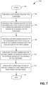
- FIG. 7 an exemplary methodology 700 for configuring a container inspection system that illuminates containers by way of light field illumination is illustrated.
- the exemplary methodology 700 starts at 702, and at 704 a light source is positioned relative to an inspection dome, such that the light source causes an exterior surface of a sidewall of a container that passes through the inspection dome to be illuminated by light field illumination.
- a first camera is positioned relative to the inspection dome, such that a field of view of the first camera encompasses the exterior surface of the sidewall of the container when the external surface is illuminated by the light field illumination.
- the first camera is configured to capture an image of the exterior surface of the sidewall of the container when the container is being transported by a conveyor through the inspection dome of the container inspection system.
- a second camera is positioned relative to the inspection dome, such that a field of view of the second camera partially overlaps with the field of view of the first camera.
- the second camera is configured to capture an image of the exterior surface of the sidewall of the container when the container is being transported by a conveyor through the inspection dome of the container inspection system.
- the first camera and the second camera are configured to generate images of the exterior surface of the sidewall of the container when the exterior surface of the sidewall of the container is illuminated by light field illumination.
- a computing system is configured to: receive the images generated by the first and the second cameras; replace a band in the first image with a band from the second image; and generate an indication as to whether or not the container is defective based upon the band in the first image being replaced with the band from the second image.
- the methodology 700 completes at 714.
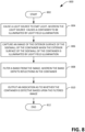
- the methodology 800 starts at 802, and at 804, a light source is caused to emit light such that exterior surface of a sidewall of the container is illuminated by light field illumination. As described previously, this is performed while the container is being transported at a relatively high rate of speed along a conveyor.
- an image of the exterior surface of the sidewall of the container is captured by a camera while the exterior surface of the sidewall of the container is illuminated by light field illumination.
- a band of the image that comprises reflections is filtered from the image, thereby creating a filtered image.
- the container is labeled as being either defective or non-defective based upon the filtered image.
- the methodology 800 completes at 812.
- the computing device 900 may be used in a system that detects color defects in containers that have been decorated with ink.
- the computing device 900 can be used in a system that detects scratches or voids in decorations (particularly decorations with ink of dark colors) in containers.
- the computing device 900 includes at least one processor 902 that executes instructions that are stored in a memory 904.
- the instructions may be, for instance, instructions for implementing functionality described as being carried out by one or more components discussed above or instructions for implementing one or more of the methods described above.
- the processor 902 may access the memory 904 by way of a system bus 906.
- the memory 904 may also store images, defect signatures, etc.
- the computing device 900 additionally includes a data store 908 that is accessible by the processor 902 by way of the system bus 906.
- the data store 908 may include executable instructions, images, etc.
- the computing device 900 also includes an input interface 910 that allows external devices to communicate with the computing device 900. For instance, the input interface 910 may be used to receive instructions from an external computer device, from a user, etc.
- the computing device 900 also includes an output interface 912 that interfaces the computing device 900 with one or more external devices. For example, the computing device 900 may display text, images, etc. by way of the output interface 912.
- the external devices that communicate with the computing device 900 via the input interface 910 and the output interface 912 can be included in an environment that provides substantially any type of user interface with which a user can interact.
- user interface types include graphical user interfaces, natural user interfaces, and so forth.
- a graphical user interface may accept input from a user employing input device(s) such as a keyboard, mouse, remote control, or the like and provide output on an output device such as a display.
- a natural user interface may enable a user to interact with the computing device 900 in a manner free from constraints imposed by input devices such as keyboards, mice, remote controls, and the like. Rather, a natural user interface can rely on speech recognition, touch and stylus recognition, gesture recognition both on screen and adjacent to the screen, air gestures, head and eye tracking, voice and speech, vision, touch, gestures, machine intelligence, and so forth.
- the computing device 900 may be a distributed system. Thus, for instance, several devices may be in communication by way of a network connection and may collectively perform tasks described as being performed by the computing device 900.
- Computer-readable media includes computer-readable storage media.
- a computer-readable storage media can be any available storage media that can be accessed by a computer.
- such computer-readable storage media can comprise RAM, ROM, EEPROM, CD-ROM or other optical disk storage, magnetic disk storage or other magnetic storage devices, or any other medium that can be used to carry or store desired program code in the form of instructions or data structures and that can be accessed by a computer.
- Disk and disc include compact disc (CD), laser disc, optical disc, digital versatile disc (DVD), floppy disk, and Blu-ray disc (BD), where disks usually reproduce data magnetically and discs usually reproduce data optically with lasers. Further, a propagated signal is not included within the scope of computer-readable storage media.
- Computer-readable media also includes communication media including any medium that facilitates transfer of a computer program from one place to another. A connection, for instance, can be a communication medium.
- the software is transmitted from a website, server, or other remote source using a coaxial cable, fiber optic cable, twisted pair, digital subscriber line (DSL), or wireless technologies such as infrared, radio, and microwave
- coaxial cable, fiber optic cable, twisted pair, DSL, or wireless technologies such as infrared, radio and microwave
- the coaxial cable, fiber optic cable, twisted pair, DSL, or wireless technologies such as infrared, radio and microwave
- the functionally described herein can be performed, at least in part, by one or more hardware logic components.
- illustrative types of hardware logic components include Field-programmable Gate Arrays (FPGAs), Program-specific Integrated Circuits (ASICs), Program-specific Standard Products (ASSPs), System-on-a-chip systems (SOCs), Complex Programmable Logic Devices (CPLDs), etc.
Landscapes
- Engineering & Computer Science (AREA)
- Physics & Mathematics (AREA)
- General Physics & Mathematics (AREA)
- Immunology (AREA)
- Health & Medical Sciences (AREA)
- Biochemistry (AREA)
- General Health & Medical Sciences (AREA)
- Chemical & Material Sciences (AREA)
- Life Sciences & Earth Sciences (AREA)
- Pathology (AREA)
- Analytical Chemistry (AREA)
- Multimedia (AREA)
- Signal Processing (AREA)
- Theoretical Computer Science (AREA)
- Computer Vision & Pattern Recognition (AREA)
- Quality & Reliability (AREA)
- Computing Systems (AREA)
- Spectroscopy & Molecular Physics (AREA)
- Investigating Materials By The Use Of Optical Means Adapted For Particular Applications (AREA)
Claims (8)
- Behälterinspektionssystem (100), umfassend:eine Inspektionskuppel (108), wobei eine Innenfläche der Inspektionskuppel reflektierend ist, und wobei die Inspektionskuppel ferner eine Eingangsöffnung (110) und eine Ausgangsöffnung (112) umfasst, wobei eine Fördervorrichtung (102) konfiguriert ist, einen Behälter durch die Eingangsöffnung in die Inspektionskuppel zu transportieren, und wobei die Fördervorrichtung ferner konfiguriert ist, den Behälter durch die Ausgangsöffnung aus der Inspektionskuppel herauszutransportieren;eine Lichtquelle (126), die konfiguriert ist, Licht in die Inspektionskuppel diffus zu emittieren, sodass eine Außenfläche einer Seitenwand des Behälters durch Lichtfeldbeleuchtung beleuchtet wird, wenn sich der Behälter in der Inspektionskuppel befindet;eine erste Kamera, die konfiguriert ist, ein erstes Bild der Außenfläche der Seitenwand des Behälters zu erzeugen, wenn die Außenfläche durch Lichtfeldbeleuchtung beleuchtet wird;eine zweite Kamera, die konfiguriert ist, ein zweites Bild der Außenfläche der Seitenwand des Behälters aufzunehmen, wenn die Außenfläche durch Lichtfeldbeleuchtung beleuchtet wird; undein Computersystem (124) in Kommunikation mit der Kamera, wobei das Computersystem konfiguriert ist zum:Identifizieren eines ersten Bandes des ersten Bildes basierend auf einer Position der ersten Kamera relativ zu dem Behälter, wenn das Bild des Behälters durch die erste Kamera erzeugt wurde, wobei das erste Band eine Reflexion in der Außenfläche der Seitenwand des Behälters darstellt;Ersetzen des ersten Bandes des ersten Bildes durch ein zweites Band von dem zweiten Bild, wobei das zweite Bild gleichzeitig mit dem ersten Bild erzeugt wird; undAusgeben eines Hinweises, ob der Behälter defekt ist, basierend auf dem ersten Band des ersten Bildes, das durch das zweite Band des zweiten Bildes ersetzt wurde.
- Behälterinspektionssystem nach Anspruch 1, wobei das zweite Band von dem zweiten Bild basierend auf einer Position der zweiten Kamera relativ zu dem Behälter identifiziert wird, wenn das zweite Bild der Außenfläche der Seitenwand des Behälters von der zweiten Kamera erzeugt wurde.
- Behälterinspektionssystem nach Anspruch 1, wobei das Computersystem ferner konfiguriert ist zum:Ausführen einer kolorimetrischen Messung an mindestens einem Abschnitt des ersten Bildes; undAusgeben des Hinweises, ob der Behälter defekt ist, basierend auf der kolorimetrischen Messung.
- Behälterinspektionssystem nach Anspruch 1, wobei das Computersystem konfiguriert ist, den Hinweis basierend auf dem zweiten Bild auszugeben.
- Behälterinspektionssystem nach Anspruch 1, ferner umfassend:
mehrere Kameras, die symmetrisch um die Inspektionskuppel herum angeordnet sind, wobei die erste Kamera und die zweite Kamera in den mehreren Kameras enthalten sind. - Behälterinspektionssystem nach Anspruch 1, ferner umfassend eine zweite Lichtquelle, die konfiguriert ist, kollimiertes Licht zu emittieren, wobei die zweite Lichtquelle konfiguriert ist, die Außenfläche der Seitenwand des Behälters mittels Dunkelfeldbeleuchtung zu beleuchten.
- Behälterinspektionssystem nach Anspruch 6, wobei das Computersystem konfiguriert ist, die Lichtquelle, die zweite Lichtquelle und die erste Kamera derart zu steuern, dass die erste Kamera zusätzlich konfiguriert ist, ein drittes Bild der Außenfläche der Seitenwand des Behälters aufzunehmen, wenn die Außenfläche der Seitenwand des Behälters durch die zweite Lichtquelle beleuchtet wird.
- Behälterinspektionssystem nach Anspruch 1, wobei das Computersystem ferner konfiguriert ist zum:Erzeugen eines abgewickelten Bildes des Behälters basierend auf mehreren Bildern des Behälters, wobei die mehreren Bilder des Behälters gleichzeitig aufgenommen werden, wenn sich der Behälter in der Inspektionskuppel befindet;Abgleichen des abgewickelten Bildes des Behälters mit einem statistischen Modell, wobei das statistische Modell ein Modell eines nichtdefekten Behälters ist;Vergleichen des abgewickelten Bildes mit dem statistischen Modell; undAusgeben eines Hinweises, ob der Behälter defekt ist, basierend auf dem Vergleich.
Priority Applications (1)
| Application Number | Priority Date | Filing Date | Title |
|---|---|---|---|
| RS20250499A RS66818B1 (sr) | 2017-01-11 | 2018-01-04 | Sistem za inspekciju kontejnera sa osvetljenjem svetlog polja |
Applications Claiming Priority (2)
| Application Number | Priority Date | Filing Date | Title |
|---|---|---|---|
| US15/404,148 US10309908B2 (en) | 2017-01-11 | 2017-01-11 | Light field illumination container inspection system |
| PCT/US2018/012328 WO2018132294A1 (en) | 2017-01-11 | 2018-01-04 | Light field illumination container inspection system |
Publications (4)
| Publication Number | Publication Date |
|---|---|
| EP3568977A1 EP3568977A1 (de) | 2019-11-20 |
| EP3568977A4 EP3568977A4 (de) | 2020-12-02 |
| EP3568977B1 true EP3568977B1 (de) | 2025-03-05 |
| EP3568977C0 EP3568977C0 (de) | 2025-03-05 |
Family
ID=62782960
Family Applications (1)
| Application Number | Title | Priority Date | Filing Date |
|---|---|---|---|
| EP18738516.6A Active EP3568977B1 (de) | 2017-01-11 | 2018-01-04 | Behälterinspektionssystem mit hellfeld-beleuchtung |
Country Status (7)
| Country | Link |
|---|---|
| US (1) | US10309908B2 (de) |
| EP (1) | EP3568977B1 (de) |
| ES (1) | ES3029746T3 (de) |
| HU (1) | HUE071638T2 (de) |
| PL (1) | PL3568977T3 (de) |
| RS (1) | RS66818B1 (de) |
| WO (1) | WO2018132294A1 (de) |
Families Citing this family (14)
| Publication number | Priority date | Publication date | Assignee | Title |
|---|---|---|---|---|
| EP3459007B1 (de) * | 2016-08-31 | 2024-05-08 | Abbott Laboratories | Systeme, vorrichtung und zugehörige verfahren zur beurteilung der integrität einer biologischen probe |
| US10645959B2 (en) * | 2016-09-19 | 2020-05-12 | Red Bull Gmbh | Method and device for treating and monitoring the quality of objects comprising metal materials |
| US10899138B2 (en) | 2017-01-11 | 2021-01-26 | Applied Vision Corporation | Container inspection system controlling printheads to correct for detected ink thickness errors |
| DE102017004358A1 (de) * | 2017-05-04 | 2018-11-08 | QuISS Qualitäts-lnspektionssysteme und Service AG | Vorrichtung und Verfahren zum Selektieren von mit hoher Geschwindigkeit bewegten Gebinden |
| DE102018111638A1 (de) * | 2018-05-15 | 2019-11-21 | Krones Ag | Verfahren zum Inspizieren von Behältnissen mit Petitionsbestimmung |
| CN108776808A (zh) * | 2018-05-25 | 2018-11-09 | 北京百度网讯科技有限公司 | 一种用于检测钢包溶蚀缺陷的方法和装置 |
| CH716479A1 (de) * | 2019-08-02 | 2021-02-15 | Finatec Holding Ag | Verfahren und Vorrichtung zur optischen Prüfung von Hohlkörpern. |
| US11536655B1 (en) | 2020-02-18 | 2022-12-27 | Path AI, Inc. | Imaging systems with angled sensors and related methods |
| JP7416231B2 (ja) * | 2020-05-21 | 2024-01-17 | 日本電気株式会社 | 設置支援装置、設置支援方法、およびプログラム |
| EP3916379B1 (de) * | 2020-05-29 | 2025-04-09 | Becton Dickinson France | Verfahren zur inspektion eines medizinischen behälters und dafür verwendetes system |
| US12254383B2 (en) * | 2021-03-30 | 2025-03-18 | Accenture Global Solutions Limited | Intelligent real-time defect prediction, detection, and AI driven automated correction solution |
| JP7136271B1 (ja) | 2021-05-13 | 2022-09-13 | 東洋製罐株式会社 | 検査装置及び検査方法 |
| US12517006B2 (en) * | 2021-08-10 | 2026-01-06 | Johnson & Johnson Vision Care, Inc. | Quality control for sealed lens packages |
| JP7493541B2 (ja) * | 2022-01-31 | 2024-05-31 | アンリツ株式会社 | 検査装置 |
Family Cites Families (35)
| Publication number | Priority date | Publication date | Assignee | Title |
|---|---|---|---|---|
| JPS61100604A (ja) * | 1984-10-24 | 1986-05-19 | Hajime Sangyo Kk | 表面検査装置 |
| US4691231A (en) | 1985-10-01 | 1987-09-01 | Vistech Corporation | Bottle inspection system |
| US5095204A (en) * | 1990-08-30 | 1992-03-10 | Ball Corporation | Machine vision inspection system and method for transparent containers |
| US5495429A (en) * | 1993-02-12 | 1996-02-27 | West Virginia University | Method and apparatus for measuring the color of three dimensional objects |
| US5987161A (en) * | 1994-06-30 | 1999-11-16 | Texas Instruments Incorporated | Apparatus and method for identifying defective objects |
| US5510610A (en) * | 1994-10-07 | 1996-04-23 | Emhart Glass Machinery Investments Inc. | Apparatus for detecting defects on the bottom of bottles by manipulating an image to remove knurls |
| NO316962B1 (no) * | 1996-07-12 | 2004-07-12 | Tomra Systems Asa | Anordning for handtering av beholdere |
| EP0873510B1 (de) * | 1996-10-30 | 2006-02-01 | Krones Aktiengesellschaft | Inspektionsvorrichtung für flaschen oder dgl. |
| US5982941A (en) * | 1997-02-07 | 1999-11-09 | Eastman Kodak Company | Method of producing digital image with improved performance characteristic |
| US6404516B1 (en) * | 1999-02-22 | 2002-06-11 | Applied Science Fiction, Inc. | Parametric image stitching |
| US6781620B1 (en) | 1999-03-16 | 2004-08-24 | Eastman Kodak Company | Mixed-element stitching and noise reduction system |
| US6549647B1 (en) * | 2000-01-07 | 2003-04-15 | Cyberoptics Corporation | Inspection system with vibration resistant video capture |
| FR2806478B1 (fr) * | 2000-03-14 | 2002-05-10 | Optomachines | Dispositif et procede de controle optique de pieces de vaisselle comme des assiettes emaillees ou tout produit ceramique emaille |
| US6621569B2 (en) | 2000-05-26 | 2003-09-16 | Applied Vision Company Llc | Illuminator for machine vision |
| GB2372391A (en) * | 2001-02-16 | 2002-08-21 | Hewlett Packard Co | Removal of specular reflection |
| FR2846424B1 (fr) | 2002-10-25 | 2006-02-03 | Bsn Glasspack | Procede et dispositif d'eclairage pour detecter des defaut et/ou de manque de matiere sur la bague d'un recipient transparent ou translucide |
| US20040150815A1 (en) * | 2003-02-05 | 2004-08-05 | Applied Vision Company, Llc | Flaw detection in objects and surfaces |
| US7187797B2 (en) | 2003-04-01 | 2007-03-06 | Applied Vision Company, Llc | Color machine vision system for colorimetry |
| DE102004040164A1 (de) * | 2004-08-19 | 2006-03-02 | Khs Maschinen- Und Anlagenbau Ag | Vorrichtung zur Erfassung von Strukturen, wie Profilierungen oder Prägungen an Körpern von Flaschen oder dergl. Behälter |
| US7751602B2 (en) | 2004-11-18 | 2010-07-06 | Mcgill University | Systems and methods of classification utilizing intensity and spatial data |
| FR2884317B1 (fr) * | 2005-04-06 | 2007-06-22 | Tiama Sa | Procede et dispositif pour supprimer les reflets parasites lors de l'inspection a chaud d'objets creux translucides ou transparents |
| US7626158B2 (en) | 2006-10-23 | 2009-12-01 | Emhart Glass S.A. | Machine for inspecting glass containers |
| DE102007054657A1 (de) * | 2006-11-15 | 2008-07-03 | Loell Industry Solutions Gmbh | Optische Erfassungseinrichtung, insbesondere zur Inspektion von Flaschen, sowie entsprechendes Visualisierungsverfahren |
| US8135206B2 (en) * | 2007-05-02 | 2012-03-13 | Emhart Glass S.A. | Machine for inspecting glass containers |
| US8179434B2 (en) * | 2008-05-09 | 2012-05-15 | Mettler-Toledo, LLC | System and method for imaging of curved surfaces |
| JP4900377B2 (ja) * | 2008-12-16 | 2012-03-21 | 株式会社デンソー | 画像処理装置 |
| DE102010032166B4 (de) * | 2010-07-23 | 2016-03-10 | Khs Gmbh | Erfassungssystem und Inspektionsverfahren zur Flaschennaht- und Embossingausrichtung |
| DE102011083377A1 (de) * | 2011-09-26 | 2013-03-28 | Krones Aktiengesellschaft | Vorrichtung und Verfahren zum Ausrichten von Behältern |
| JP6111730B2 (ja) | 2012-03-28 | 2017-04-12 | 株式会社リコー | 測色装置、画像形成装置、測色システムおよび測色方法 |
| NL2009980C2 (en) * | 2012-12-13 | 2014-06-16 | Ct Voor Tech Informatica B V | A method of producing glass products from glass product material and an assembly for performing said method. |
| DE102014002582B4 (de) * | 2014-02-26 | 2018-10-11 | Heye International Gmbh | Verfahren zur Erkennung von Rissen in den Wandungen von Hohlglasartikeln |
| CN103888689B (zh) * | 2014-03-13 | 2017-10-31 | 北京智谷睿拓技术服务有限公司 | 图像采集方法及图像采集装置 |
| US9367895B2 (en) * | 2014-03-19 | 2016-06-14 | Digitalglobe, Inc. | Automated sliver removal in orthomosaic generation |
| US11308601B2 (en) | 2015-04-29 | 2022-04-19 | Emhart Glass S.A. | Container inspection system with individual light control |
| US11828712B2 (en) * | 2015-06-03 | 2023-11-28 | Industrial Dynamic Company, Ltd | System and method for inspecting containers using multiple radiation sources |
-
2017
- 2017-01-11 US US15/404,148 patent/US10309908B2/en active Active
-
2018
- 2018-01-04 EP EP18738516.6A patent/EP3568977B1/de active Active
- 2018-01-04 ES ES18738516T patent/ES3029746T3/es active Active
- 2018-01-04 HU HUE18738516A patent/HUE071638T2/hu unknown
- 2018-01-04 PL PL18738516.6T patent/PL3568977T3/pl unknown
- 2018-01-04 WO PCT/US2018/012328 patent/WO2018132294A1/en not_active Ceased
- 2018-01-04 RS RS20250499A patent/RS66818B1/sr unknown
Also Published As
| Publication number | Publication date |
|---|---|
| US20180195974A1 (en) | 2018-07-12 |
| EP3568977A4 (de) | 2020-12-02 |
| HUE071638T2 (hu) | 2025-09-28 |
| RS66818B1 (sr) | 2025-06-30 |
| EP3568977A1 (de) | 2019-11-20 |
| WO2018132294A1 (en) | 2018-07-19 |
| PL3568977T3 (pl) | 2025-08-18 |
| ES3029746T3 (en) | 2025-06-25 |
| EP3568977C0 (de) | 2025-03-05 |
| US10309908B2 (en) | 2019-06-04 |
Similar Documents
| Publication | Publication Date | Title |
|---|---|---|
| EP3568977B1 (de) | Behälterinspektionssystem mit hellfeld-beleuchtung | |
| US10899138B2 (en) | Container inspection system controlling printheads to correct for detected ink thickness errors | |
| US10147176B1 (en) | Automated container inspection system | |
| US10794838B2 (en) | Method and device for detecting defect of cover lens in laser welding system on automobile production line | |
| US5095204A (en) | Machine vision inspection system and method for transparent containers | |
| EP3583397B1 (de) | Vorrichtung zur erkennung und überprüfung von defekten eines reifens am ende eines produktionsprozesses | |
| US10422755B2 (en) | Identifying defects in transparent containers | |
| US12288390B2 (en) | System and method of object detection using AI deep learning models | |
| US20060251315A1 (en) | Defect inspection method and defect inspection system using the method | |
| RU2310828C2 (ru) | Способ и устройство, предназначенные, в том числе, для отбора контейнера | |
| JPH05232030A (ja) | カラーラベルの無接触型鑑定・検査装置及び方法 | |
| JP2011133496A (ja) | 容器の汚染を検出する装置および方法 | |
| US10885621B2 (en) | Contact lens inspection in a plastic shell | |
| US20030179920A1 (en) | Inspection system for determining object orientation and defects | |
| JP2017198612A (ja) | 検査装置、検査システム、および物品製造方法 | |
| CN115428015A (zh) | 用于光学检查饮料处理系统中的容器的方法和设备 | |
| US10393670B1 (en) | Container inspection system | |
| KR101936974B1 (ko) | 보틀캔의 구금부 검사 방법 및 검사 장치 | |
| JPH0736004B2 (ja) | 検査方法及び装置 | |
| CN111426693A (zh) | 一种质量缺陷检测系统及其检测方法 | |
| Laucka et al. | Research of the defects in anesthetic masks | |
| EP4591053A2 (de) | Inspektionssystem für glasbehälter | |
| Zeuch | Understanding and applying machine vision, revised and expanded | |
| US20260011035A1 (en) | Inspecting colors of containers after printing | |
| Bračun et al. | A visual inspection system for KTL coatings |
Legal Events
| Date | Code | Title | Description |
|---|---|---|---|
| STAA | Information on the status of an ep patent application or granted ep patent |
Free format text: STATUS: THE INTERNATIONAL PUBLICATION HAS BEEN MADE |
|
| PUAI | Public reference made under article 153(3) epc to a published international application that has entered the european phase |
Free format text: ORIGINAL CODE: 0009012 |
|
| STAA | Information on the status of an ep patent application or granted ep patent |
Free format text: STATUS: REQUEST FOR EXAMINATION WAS MADE |
|
| 17P | Request for examination filed |
Effective date: 20190626 |
|
| AK | Designated contracting states |
Kind code of ref document: A1 Designated state(s): AL AT BE BG CH CY CZ DE DK EE ES FI FR GB GR HR HU IE IS IT LI LT LU LV MC MK MT NL NO PL PT RO RS SE SI SK SM TR |
|
| AX | Request for extension of the european patent |
Extension state: BA ME |
|
| RIN1 | Information on inventor provided before grant (corrected) |
Inventor name: MURDOCH, BRYAN Inventor name: KRESS, MICHAEL LEO |
|
| DAV | Request for validation of the european patent (deleted) | ||
| DAX | Request for extension of the european patent (deleted) | ||
| RIC1 | Information provided on ipc code assigned before grant |
Ipc: G01N 21/90 20060101ALI20200729BHEP Ipc: G01N 21/88 20060101ALI20200729BHEP Ipc: G06T 7/00 20170101ALI20200729BHEP Ipc: G06K 9/00 20060101ALI20200729BHEP Ipc: H04N 5/225 20060101ALI20200729BHEP Ipc: H04N 5/247 20060101ALI20200729BHEP Ipc: H04N 7/18 20060101AFI20200729BHEP |
|
| A4 | Supplementary search report drawn up and despatched |
Effective date: 20201104 |
|
| RIC1 | Information provided on ipc code assigned before grant |
Ipc: G01N 21/88 20060101ALI20201029BHEP Ipc: G06K 9/00 20060101ALI20201029BHEP Ipc: G06T 7/00 20170101ALI20201029BHEP Ipc: H04N 5/247 20060101ALI20201029BHEP Ipc: G01N 21/90 20060101ALI20201029BHEP Ipc: H04N 5/225 20060101ALI20201029BHEP Ipc: H04N 7/18 20060101AFI20201029BHEP |
|
| STAA | Information on the status of an ep patent application or granted ep patent |
Free format text: STATUS: EXAMINATION IS IN PROGRESS |
|
| 17Q | First examination report despatched |
Effective date: 20220929 |
|
| REG | Reference to a national code |
Ref country code: DE Ref legal event code: R079 Free format text: PREVIOUS MAIN CLASS: H04N0007180000 Ipc: H04N0023560000 Ref document number: 602018079799 Country of ref document: DE |
|
| GRAP | Despatch of communication of intention to grant a patent |
Free format text: ORIGINAL CODE: EPIDOSNIGR1 |
|
| STAA | Information on the status of an ep patent application or granted ep patent |
Free format text: STATUS: GRANT OF PATENT IS INTENDED |
|
| RIC1 | Information provided on ipc code assigned before grant |
Ipc: H04N 23/90 20230101ALI20240906BHEP Ipc: H04N 7/18 20060101ALI20240906BHEP Ipc: G06T 7/00 20170101ALI20240906BHEP Ipc: G01N 21/88 20060101ALI20240906BHEP Ipc: G01N 21/90 20060101ALI20240906BHEP Ipc: H04N 23/957 20230101ALI20240906BHEP Ipc: H04N 23/56 20230101AFI20240906BHEP |
|
| INTG | Intention to grant announced |
Effective date: 20240920 |
|
| GRAS | Grant fee paid |
Free format text: ORIGINAL CODE: EPIDOSNIGR3 |
|
| GRAA | (expected) grant |
Free format text: ORIGINAL CODE: 0009210 |
|
| STAA | Information on the status of an ep patent application or granted ep patent |
Free format text: STATUS: THE PATENT HAS BEEN GRANTED |
|
| AK | Designated contracting states |
Kind code of ref document: B1 Designated state(s): AL AT BE BG CH CY CZ DE DK EE ES FI FR GB GR HR HU IE IS IT LI LT LU LV MC MK MT NL NO PL PT RO RS SE SI SK SM TR |
|
| REG | Reference to a national code |
Ref country code: GB Ref legal event code: FG4D |
|
| REG | Reference to a national code |
Ref country code: CH Ref legal event code: EP |
|
| REG | Reference to a national code |
Ref country code: DE Ref legal event code: R096 Ref document number: 602018079799 Country of ref document: DE |
|
| REG | Reference to a national code |
Ref country code: IE Ref legal event code: FG4D |
|
| U01 | Request for unitary effect filed |
Effective date: 20250325 |
|
| U07 | Unitary effect registered |
Designated state(s): AT BE BG DE DK EE FI FR IT LT LU LV MT NL PT RO SE SI Effective date: 20250401 |
|
| REG | Reference to a national code |
Ref country code: ES Ref legal event code: FG2A Ref document number: 3029746 Country of ref document: ES Kind code of ref document: T3 Effective date: 20250625 |
|
| PG25 | Lapsed in a contracting state [announced via postgrant information from national office to epo] |
Ref country code: NO Free format text: LAPSE BECAUSE OF FAILURE TO SUBMIT A TRANSLATION OF THE DESCRIPTION OR TO PAY THE FEE WITHIN THE PRESCRIBED TIME-LIMIT Effective date: 20250605 |
|
| PG25 | Lapsed in a contracting state [announced via postgrant information from national office to epo] |
Ref country code: HR Free format text: LAPSE BECAUSE OF FAILURE TO SUBMIT A TRANSLATION OF THE DESCRIPTION OR TO PAY THE FEE WITHIN THE PRESCRIBED TIME-LIMIT Effective date: 20250305 |
|
| REG | Reference to a national code |
Ref country code: SK Ref legal event code: T3 Ref document number: E 46474 Country of ref document: SK |
|
| REG | Reference to a national code |
Ref country code: GR Ref legal event code: EP Ref document number: 20250401061 Country of ref document: GR Effective date: 20250613 |
|
| REG | Reference to a national code |
Ref country code: HU Ref legal event code: AG4A Ref document number: E071638 Country of ref document: HU |
|
| PG25 | Lapsed in a contracting state [announced via postgrant information from national office to epo] |
Ref country code: SM Free format text: LAPSE BECAUSE OF FAILURE TO SUBMIT A TRANSLATION OF THE DESCRIPTION OR TO PAY THE FEE WITHIN THE PRESCRIBED TIME-LIMIT Effective date: 20250305 |
|
| PG25 | Lapsed in a contracting state [announced via postgrant information from national office to epo] |
Ref country code: IS Free format text: LAPSE BECAUSE OF FAILURE TO SUBMIT A TRANSLATION OF THE DESCRIPTION OR TO PAY THE FEE WITHIN THE PRESCRIBED TIME-LIMIT Effective date: 20250705 |
|
| PLBE | No opposition filed within time limit |
Free format text: ORIGINAL CODE: 0009261 |
|
| STAA | Information on the status of an ep patent application or granted ep patent |
Free format text: STATUS: NO OPPOSITION FILED WITHIN TIME LIMIT |
|
| REG | Reference to a national code |
Ref country code: CH Ref legal event code: L10 Free format text: ST27 STATUS EVENT CODE: U-0-0-L10-L00 (AS PROVIDED BY THE NATIONAL OFFICE) Effective date: 20260114 |
|
| PGFP | Annual fee paid to national office [announced via postgrant information from national office to epo] |
Ref country code: CZ Payment date: 20251219 Year of fee payment: 9 |
|
| PGFP | Annual fee paid to national office [announced via postgrant information from national office to epo] |
Ref country code: SK Payment date: 20251223 Year of fee payment: 9 |
|
| PGFP | Annual fee paid to national office [announced via postgrant information from national office to epo] |
Ref country code: RS Payment date: 20251218 Year of fee payment: 9 |
|
| REG | Reference to a national code |
Ref country code: CH Ref legal event code: U11 Free format text: ST27 STATUS EVENT CODE: U-0-0-U10-U11 (AS PROVIDED BY THE NATIONAL OFFICE) Effective date: 20260201 |