EP3583397B1 - Vorrichtung zur erkennung und überprüfung von defekten eines reifens am ende eines produktionsprozesses - Google Patents
Vorrichtung zur erkennung und überprüfung von defekten eines reifens am ende eines produktionsprozesses Download PDFInfo
- Publication number
- EP3583397B1 EP3583397B1 EP18722715.2A EP18722715A EP3583397B1 EP 3583397 B1 EP3583397 B1 EP 3583397B1 EP 18722715 A EP18722715 A EP 18722715A EP 3583397 B1 EP3583397 B1 EP 3583397B1
- Authority
- EP
- European Patent Office
- Prior art keywords
- tire
- defects
- profilometer
- laser
- laser profilometer
- Prior art date
- Legal status (The legal status is an assumption and is not a legal conclusion. Google has not performed a legal analysis and makes no representation as to the accuracy of the status listed.)
- Active
Links
Images


Classifications
-
- B—PERFORMING OPERATIONS; TRANSPORTING
- B60—VEHICLES IN GENERAL
- B60C—VEHICLE TYRES; TYRE INFLATION; TYRE CHANGING; CONNECTING VALVES TO INFLATABLE ELASTIC BODIES IN GENERAL; DEVICES OR ARRANGEMENTS RELATED TO TYRES
- B60C25/00—Apparatus or tools adapted for mounting, removing or inspecting tyres
- B60C25/002—Inspecting tyres
-
- B—PERFORMING OPERATIONS; TRANSPORTING
- B29—WORKING OF PLASTICS; WORKING OF SUBSTANCES IN A PLASTIC STATE IN GENERAL
- B29D—PRODUCING PARTICULAR ARTICLES FROM PLASTICS OR FROM SUBSTANCES IN A PLASTIC STATE
- B29D30/00—Producing pneumatic or solid tyres or parts thereof
- B29D30/06—Pneumatic tyres or parts thereof (e.g. produced by casting, moulding, compression moulding, injection moulding, centrifugal casting)
- B29D30/0601—Vulcanising tyres; Vulcanising presses for tyres
- B29D30/0633—After-treatment specially adapted for vulcanising tyres
-
- B—PERFORMING OPERATIONS; TRANSPORTING
- B60—VEHICLES IN GENERAL
- B60C—VEHICLE TYRES; TYRE INFLATION; TYRE CHANGING; CONNECTING VALVES TO INFLATABLE ELASTIC BODIES IN GENERAL; DEVICES OR ARRANGEMENTS RELATED TO TYRES
- B60C25/00—Apparatus or tools adapted for mounting, removing or inspecting tyres
- B60C25/002—Inspecting tyres
- B60C25/005—Inspecting tyres inside surface
-
- G—PHYSICS
- G01—MEASURING; TESTING
- G01M—TESTING STATIC OR DYNAMIC BALANCE OF MACHINES OR STRUCTURES; TESTING OF STRUCTURES OR APPARATUS, NOT OTHERWISE PROVIDED FOR
- G01M17/00—Testing of vehicles
- G01M17/007—Wheeled or endless-tracked vehicles
- G01M17/02—Tyres
- G01M17/021—Tyre supporting devices, e.g. chucks
-
- G—PHYSICS
- G01—MEASURING; TESTING
- G01M—TESTING STATIC OR DYNAMIC BALANCE OF MACHINES OR STRUCTURES; TESTING OF STRUCTURES OR APPARATUS, NOT OTHERWISE PROVIDED FOR
- G01M17/00—Testing of vehicles
- G01M17/007—Wheeled or endless-tracked vehicles
- G01M17/02—Tyres
- G01M17/027—Tyres using light, e.g. infrared, ultraviolet or holographic techniques
-
- B—PERFORMING OPERATIONS; TRANSPORTING
- B29—WORKING OF PLASTICS; WORKING OF SUBSTANCES IN A PLASTIC STATE IN GENERAL
- B29D—PRODUCING PARTICULAR ARTICLES FROM PLASTICS OR FROM SUBSTANCES IN A PLASTIC STATE
- B29D30/00—Producing pneumatic or solid tyres or parts thereof
- B29D30/06—Pneumatic tyres or parts thereof (e.g. produced by casting, moulding, compression moulding, injection moulding, centrifugal casting)
- B29D30/0601—Vulcanising tyres; Vulcanising presses for tyres
- B29D30/0633—After-treatment specially adapted for vulcanising tyres
- B29D2030/0634—Measuring, calculating, correcting tyre uniformity, e.g. correcting RFV
- B29D2030/0635—Measuring and calculating tyre uniformity, e.g. using mathematical methods
Definitions
- the present invention relates to the field of the systems for the automation of the industrial production process of tires.
- the present invention relates to an apparatus and respective process for detecting the possible presence of defects on all surfaces of a tire at the end of the production process.
- Tire, or pneumatics are the elements which are mounted on the wheels and which allow the grip of the vehicle on the road.
- the production process of a tire is based on the following main steps:
- Tire quality control is one of the most sensitive processes and the check for absence of defects on the product, which may have been occurred during the production process before marketing, is essential and must be performed on all manufactured tires; installing a machine which efficiently checks the absence of defects on the manufactured tires, positively improves the quality on tires production line.
- defects means any deviation from a desired condition, independently from whether such a deviation causes a degradation in performance of the tire (which can thus be rejected or declassed) or may be a simple defect (e.g. concerning appearance), which does not cause the rejecting or declassing of the tire. Defects can be:
- This type of "human” visual check has criticalities due to the repeatability of the operation, to the complexity of the parts to be analyzed and to the short and fast times imposed by the industrial production, and further does not provide an objective test of the tire because it is related to the conditions of the operators who are subject to many factors, such as fatigue, stress, physical state and other contingent factors, performing their task.
- the technology progresses such as the tire automation production processes, may make it possible to reduce said criticalities and costs to benefit result objectivity.
- Tire manufacturers are also seeking automated solutions for the defect checking activities which until now have been performed solely by operators who, because of long working shifts, wrongly release to the market many defective products, recurrent false negatives which at the end may damage corporate image reputation and customer retention, discarded products and environmental waste of raw materials and resources, and, ultimately, risks to the safety of drivers on the roads.
- Patents relating to systems and methods for testing tires are known in the prior art; some of the most relevant patents are listed below.
- Patent document EP1148328 illustrates a method consisting in varying the pressure of a tire, causing consequent changes in the shape of the tire and of the structural features/defects; the light projected in particular points on the surface of the tire by means of triangulation is observed and acquired by a camera, the images are sent to a processing system and a model of the tire is processed, the process is repeated and the various models are compared for various tire pressures.
- Patent document WO2013/045594 describes a rapid analysis method of elements in relief on the inner surface of a tire, comprising the steps of: capturing a three-dimensional image of the surface by assigning to each pixel of the image a grayscale value proportional to the topographical elevation of that point, in order to obtain a starting image; transforming the captured image into an orthogonal reference system, in which the abscissa axis represents the circumferential values, and the ordinate axis represents the radial values; assigning to each pixel of the surface a value of height gradient by comparing its elevation with the elevation of a discrete and reduced number of points disposed on a straight line passing through the respective pixel and oriented in the circumferential direction.
- Patent document IT102015000028956 illustrates a "Method and apparatus for detecting defects on the surface of tires" comprising the following steps: preparing the tire; acquiring a digital image, comprising a structure which comprises representative stretches of linear elements of a mesh in a surface portion and representative of possible elongated defects, said stretch of the structure having a respective orientation; providing a model of the mesh in the surface portion, in which each pixel is associated with a first index representing whether the pixel belongs to a mesh portion or not and a second index representative of an orientation at least local of the mesh stretch passing through said pixel; calculating for each pixel of the structure a third index representative of the orientation of the stretch of structure passing through said pixel; and determining, for each pixel of the structure having a corresponding pixel in the mesh pattern belonging to the mesh, if said pixel of the structure belongs to a predetermined defect on the basis of the comparison of the third index and the second index associated with the corresponding pixel in the mesh model.
- Patent document US2016320265 illustrates a method for detecting defects on tires in a tire production process and includes the following steps: providing a tire; acquiring a three-dimensional image of a surface portion of the tire; generating, as a function of the acquired image, a plurality of values which indicate the measure of a profile height of the tire surface portion to be tested; processing, as a function of the plurality of acquired values and according to an interpolation of a plurality of values which indicate an estimation of the tire surface portion to be tested with respect to a reference profile; calculating, as a function of said measured values respect to those of a reference profile, and comparing the values obtained in order to detect possible defects on the tire surface portion.
- the technology underlying said method uses matrix cameras detecting defects only on surface portions of a tire and not on the entire tire; the method does not detect defects by means of techniques based on RGB color detection.
- Patent document WO2016103131 illustrates a method and an apparatus for detecting defects on tires based on a comparison between a reference image of a defect-free portion of the surface of a tire and a sample image of a portion of the surface of the tire to be tested, illuminated by a sidelight source in order to detect possible defects.
- the method according to the said document uses a specific apparatus and is not a complete machine; it tests portions of the surface of the tire and not the entire tire; in order to detect the defects, it uses a technology which is based on the use of sidelight to highlight protrusions or defects of the tire to be tested and to provide a model of it by acquiring two-dimensional images and not provide a three-dimensional model.
- differential expansion (or contraction) of s of a tire sidewall is measured by constructing height profiles of the tire at each of at least two different static pressures to detect defects in the tire; light sources project a plurality of illuminated lines onto a tire and cameras are used to record the position of the lines to construct the height profiles of a rotationally fixed position tire.
- the method is based on the detection of macroscopic defects by inflating the tire at different pressures and consequently examining the variation of the positions of the light lines projected onto the tire and acquired by a camera; it does not perform any detection 3D and cannot examine for small deformations and defects on the surface of the tire to be tested.
- the method is used to detect large structural defects of the tire which are highlighted by inflating the tire at different pressures and plotting the profile of the tire as a function of the position of the projected lines. In all cases, as the tire must be inflated, it must be mounted on a rim and the apparatus is designed to test off-line. Furthermore, said method cannot be applied to the inner sections of the tire.
- the surface of the tire to be analyzed is irradiated with polarized light, the polarized light reflected by the tire surface is detected by a camera which measures its intensity and identifies irregularities; the camera is preferably equipped with a polarizer having at least three or more different directions.
- the aforesaid apparatus employs polarized light and a camera which allows to detect and highlight a tire defect but does not allow its characterization.
- the present patent document by using light as a significant element for detecting defects, does not allow the detection of minor defects as a result of the different reflection due to the different conformation of the tire, to its variable light absorption features as a function of the angle of incidence, of the curvature of the tire and of various sizes that the tire assumes in space at the end of the vulcanization step, when the tire is not inflated and mounted on a rim. Furthermore, said method cannot be applied to the inner sections of the tire.
- US Patent Application published as US 2001/024279 A1 discloses a method and an apparatus for inspecting appearance and shape of a subject body is provided.
- the apparatus allows to inspect defects in a portion of an inner surface of a tire.
- a first picture taking means takes a picture of a linear portion of a subject body lighted by a first slit light to obtain appearance data
- a second picture taking means takes a picture of the same linear portion lighted by a second slit light to obtain shape data
- quality of appearance and shape of the subject body is judged based on the appearance data and the shape data.
- EP 2799848 A1 discloses an appearance inspection apparatus and an appearance inspection method capable of detecting a shape, minute unevenness on the surface, shine or changes in color tone on the surface of a sample under inspection.
- the method includes the steps of acquiring reflected luminance data on the sample surface by casting a slit light having an intermediate wavelength of three types of lights having different wavelengths from each other and receiving reflected light of the slit light, acquiring surface data on the sample surface by casting two lights of different wavelengths other than the intermediate wavelength at a position other than the position illuminated by the slit light on the sample surface from two different directions so as to overlap the two lights with each other and receiving the reflected light, and detecting surface unevenness from a ratio between the intensities of the two lights, changes in color tone by combining the reflected luminance data and the surface data, and gloss on the sample surface based on the presence or absence of surface unevenness and the changes in color tone.
- the main object of the present invention is to overcome most of the drawbacks of the prior art technologies for detecting the defects of a tire by means of a complete quality control apparatus which is fully integrated and autonomous to be inserted as-is at the end of the production process.
- the present invention provides a method according to claim 5 and respective apparatus according to claim 1 for detecting the presence of defects on all the surfaces of a tire at the end of its production process by using advanced digital detection instruments, which provide high-resolution viewing.
- the amount of data collected by said digital detection means is processed by appropriate processing means, which, by means of complex specially developed algorithms, test every surface and portion of the tire, identifying possible defects and providing useful data to define the tires to be rejected or to be repaired and informations upstream of the production process to implement appropriate corrective measures to reduce rejects.
- the invention provides a method and apparatus for three-dimensional viewing and color analysis which automatically detects any defect present on the tire at the end of the production cycle.
- the apparatus uses "laser profilometry” technology to identify and recognize the defects present on the surface of a tire.
- Said products using software algorithms present onboard, enable to perform the three-dimensional analysis of small objects, measure of height, length, width, inclination and volume referred to individual surfaces.
- Said technology by means of reconstructing and the successive processing of a three-dimensional model of the entire tire, allows to detect the presence, automatically recognize and classify all types of structural defects or surface defects with high efficiency and a considerable saving in terms of time and costs. Furthermore, by using RGB color cameras, the apparatus recognizes color defects on the outer surfaces, tread and shoulder, of any tire, regardless of manufacturer and size.
- the apparatus uses five laser-camera assemblies, which enables to test all inner and outer sections of any tire, regardless of manufacturer and sizes of the tire, and three high-resolution RGB camera-illuminator assemblies, which enables to test the outer sections, tread and shoulders.
- the laser-camera assemblies and the RGB camera-illuminator assemblies mounted on automated guides with axes, are automatically positioned in programmed positions, as a function of the size of the tire to be tested in order to scan every millimeter of it.
- the three-dimensional images of all its sections and the color images of the tread and of the outer shoulders are then processed by a defect analysis software, having identified the specific portions which will be processed in case of differences with respect to the model of the tire being tested; if defects are identified, the tire will be scraped or repaired.
- the scans performed simultaneously by the profilometers and by the RGB cameras are obtained by turning at controlled speed the rotating table 17 on which the tire 21 is placed, while the detection, characterization and classification of one or more defects are performed univocally by the software by means of algorithmic matching between the detection zone of the tire sample to test, which is scanned, and the corresponding one of the defect-free reference tire sample.
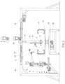
- the apparatus according to the present invention shown in some layout with a single test station ( figure 1 ) enables to check and detect the defects of the tires by means of laser profilometry technology for the acquiring the individual profiles of the surfaces to test.
- the laser profilometers 1, 2, 3, 4, 5, use triangulation method in order to detect the profile of the surfaces and perform measurements on the surfaces themselves.
- the technique is that of projecting a laser line on the surface to be tested and to continuously acquire, by means of a linear camera positioned at an angle of 25-45° with respect to the laser, the profile drawn by the light and thereby recording the dimensions along the two axes X and Z.
- the laser device performs a relative movement also along the Y axis, whereby continuously acquiring the profiles shown by the camera; said movement is obtained by rotating at controlled speed the table 17 on which the tire is placed.
- a software specifically developed for the application, performs the assembly of the single profiles acquired along the Y axis and thus allows the 3D reconstruction of the scanned surface.
- Each profilometer is provided with linear camera and independent laser, with the technical features required for the section of the tire to be analyzed (acquisition speed of the camera, resolution, optics, filters, laser power, distances between the laser and camera, framed portions, etc.).
- the apparatus requires the use of hi-tech products, selected on the market as a function of the required features and their application and integration in the system.
- the reconstruction of the three-dimensional image of the single surface is obtained starting from the primitive function obtained by means of the cameras in form of software data, or clouds of points in space of the single profiles; said primitive function are integrated in a high-level software which creates the 3D model of the entire scanned surface (tread, shoulder, bead portion).
- a suitably dimensioned laser unit-camera is installed for each of the surfaces which form the tire, inner surface 21.4 and outer surface 21.3 of the tread, inner surface 21.2 and outer surface 21.1 of the shoulder, rim-tire coupling bead portion surface 21.5, for a total of five, each of which provides the 3D image of the surface associated with it.
- All acquired images, obtained by creating a relative movement between tire and laser-camera system, are processed to obtain the 3D model of the complete tire that will be processed by the defect processing software installed on the apparatus.
- the apparatus For analyzing the defects of specific and small size portions of tire, or for small size tires, such as for example tires for motorcycles, which require less stringent technical features than those of standard products available on the market, the apparatus according to the present invention uses, for some sections of the tire, standard profilometers instead of the laser unit-camera, integrating them in the apparatus as smart sensors.
- Each profilometer acquires therefore in sequence the profiles of the section of the rotating tire, constituted by clouds of points in space, with which it is associated (tread, shoulder, etc.).
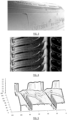
- the three-dimensional image of the surface of the tire to test, see figure 3 obtained by using the software of the apparatus, starting from the software primitive function of the cameras, contains the X-Y-Z coordinates for each point in the space of the tire itself; for example, the tread shown in fig. 4 containing an abrasion defect, shows the X-Y-Z coordinates of each point in the 3D reconstruction of the same section, see figure 5 .
- a model is created starting from a defect-free reference tire sample: all tire surfaces are scanned to create the model.
- the model creation software requires the presence of the production engineer who, by means of the user-friendly interface with which the apparatus is equipped, interacts with the system to select the portions for defining the parameters of acceptability of the tire in all its portions and for setting the parameters of each defect.
- the creation step of the 3D model it is stored in the database, matching it with the commercial code of the tire.
- the tire is tested by automatic scanning, reconstructing the 3D image and comparing the areas and portions of the tire with the corresponding default 3D model.
- the portions on which are found differences with respect to those of the default model are subjected to a successive analysis for identifying the defect: the processing is performed specifically for each classified portion in which the defect is present, according to parameters set during the model creation step.
- Figures 6 and 7 show two 3D images obtained after scanning the section of the outer shoulder of a tire: the first is the one related to the section of the shoulder of the model of the reference tire sample and the second is the same section of the tire to test, which has a defect in the highlighted portion on the inside of the rim; as can be seen, the two images are identical with the exception of the defect present inside the highlighted circle.
- the apparatus according to the present invention also allows analyzing color defects, which are very important because tire manufacturers use color for different purposes during the production step.
- the cycle described above relates to the single test station apparatus (illustrated in figure 1 ) provided with a single rotating table on which the scanning of the tread, inner and outer surface, of an outer shoulder and, after overturning of the tire, also of the other one, of an inner shoulder and, after overturning of the tire, also of the other one and of the rim-tire coupling bead portion.
- the cycle time required for analyzing a tire according to said process is about 60 seconds.
- the apparatus is equipped with two stations, which are mechanically perfectly identical and each equipped with the profilometers and RGB cameras needed for scanning the assigned surfaces.
- the operation and the defect scanning and analysis software is perfectly equal to the one installed on the single station apparatus, and the stations are duplicated only to allow scanning two tires at the same time, with an evident reduction of the cycle time, enabling to obtain cycle times of about 40 seconds for each tire during a complete test.
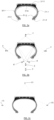
- Figures 8, 9 , 10, 11 show, as an example, some structural and surface defects which may appear on the tires; three images are associated with each defect:
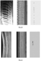
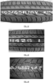
- Figures 12, 13, 14 show, as an example, some defects that may appear on the tread of a tire relative to the barcodes, lettering and commercial reference codes: incorrect positioning of lines ( figure 12 ), distorted letters ( figure 13 ), incorrect lettering positioning ( figure 14 ).
- the apparatus and the method according to the present invention allow the following improvements compared to current technologies:
- the defect detection apparatus according to the present invention is modular and is susceptible to numerous modifications and variants according to manufacturing demands, the operating principle remaining unchanged. In some manufacturing processes, it could be necessary, for example, to vary the number and the position of the detection devices (profilometers and RGB cameras) or in other cases the presence of some of them or not.
- the need may arise that the detection of color defects of the tires is not needed, or the installation of RGB cameras for detecting color defects inside the tire is needed (defects due to contamination of the rubber or escape of steam from the balloon of the vulcanization press).
- profilometers and/or additional axes in the apparatus in order to be able to scan specific parts of the tire.
- the apparatus performs the 3D reconstruction of all surfaces of a tire, also of the surfaces of the shoulders on which reference letters and commercial codes are printed; this is necessary in cases in which said codes are not supplied by the production line before setting the apparatus.
- the apparatus For recognizing said lettering and codes, the apparatus is equipped with specific software, which uses OCR (Optical Character Recognition) algorithms.
- OCR Optical Character Recognition
- the apparatus according to the present invention is also applied to maintenance checks and examinations of the state of tires outside the production process.
Landscapes
- Physics & Mathematics (AREA)
- General Physics & Mathematics (AREA)
- Engineering & Computer Science (AREA)
- Mechanical Engineering (AREA)
- Length Measuring Devices By Optical Means (AREA)
- Tyre Moulding (AREA)
- Investigating Materials By The Use Of Optical Means Adapted For Particular Applications (AREA)
- Tires In General (AREA)
- Length Measuring Devices With Unspecified Measuring Means (AREA)
Claims (5)
- Vorrichtung zum Erkennen und Prüfen von Defekten an einem Reifen am Ende eines Produktionsprozesses, bestehend aus einer Arbeitsstation, ausgestattet mit:- eine Werkbank (19), einschließlich eines Drehtisches (17) und einer automatischen Umdreheinrichtung, um einen Reifen (21) zu stützen und ihn auf dem Drehtisch (17) während der gleichen Prüfung umzudrehen,- Laser-Profilometermittel (1, 2, 3, 4, 5), konfiguriert zum Scannen und Erfassen einer Bildfolge, die sich auf das Profil der Innen- und Außenflächen des Reifens bezieht,- hochauflösende RGB-Farbkameramittel (22, 23), um die Außenflächen der Lauffläche und der Schultern des zu prüfenden Reifens abzutasten,- mechanische Mittel (7, 9, 11, 12, 13, 15, 20), die die Laserprofilometermittel (1, 2, 3, 4, 5) bzw. die Farbkameramittel (22, 23) tragen und handhaben,- Mittel (6, 8, 10, 14, 16, 18) für die elektromechanische Automatisierung (Motoren, bürstenlose Motoren, Sensoren) bzw. elektronische Geräte (programmierbare Logiksteuerung, Wechselrichter, bürstenlose Antriebsmotoren und gesteuerte Achsen), die die elektromechanischen Automatisierungsmittel verwalten und betreiben,- Prozessormittel, mit Softwaremitteln implementiert, zum Speichern und Verarbeiten der von den Laserprofilometermitteln (1, 2, 3, 4, 5) bzw. von den Farbkameramitteln (22, 23) erfassten Parameter, um ein dreidimensionales Muster des zu prüfenden Reifens als Muster der zugehörigen Größen- und Oberflächeneigenschaften, bereitzustellen und zur Verwaltung einer Datenbank mit Parametern, die sich auf die Oberflächeneigenschaften der jeweiligen Reifentypen beziehen, nach Kategorien geordnet, unter der Bedingung, dass keine Oberflächenfehler vorliegen, sowie zur Einstellung der Parameter der genannten elektronischen und elektromechanischen Automatisierungsmittel sowie die Parameter zur Überprüfung von Defekten auf derselben Reifenoberfläche,- eine auf dem Prozessormittel bereitgestellte Schnittstelle für die Interaktion zwischen dem Bediener und dem Gerät,wobei die Laserprofilometermittel (1, 2, 3, 4, 5) bzw. die Farbkameramittel (22, 23) so konfiguriert sind, dass sie eventuell vorhandene Defekte prüfen, wobei der Reifen mit kontrollierter Geschwindigkeit auf dem Drehtisch (17) rotieren kann und wobei die Softwaremittel für die anschließende Definition und Klassifizierung der Oberflächendefekte, falls erkannt, durch den algorithmischen Abgleich zwischen den von den Laserprofilometermitteln (1, 2, 3, 4, 5) bzw. den Farbkameramitteln erfassten Parametern (22, 23) konfiguriert sind, die sich auf den zu prüfenden Reifen beziehen, und mindestens einen entsprechenden Parameter, der sich auf einen Reifen derselben Kategorie bezieht, jedoch unter der Bedingung, dass keine Oberflächenfehler vorliegen,dadurch gekennzeichnet, dass die Laserprofilometermittel (1, 2, 3, 4, 5) und die hochauflösenden linearen RGB-Farbkameramittel (22, 23) für den gleichzeitigen Betrieb so konfiguriert sind, dass sie durch die elektromechanischen Automatisierungsmittel abhängig von der Größe des zu testenden Reifens automatisch in vorprogrammierten Positionen positioniert werden und einen vollständigen Scan aller Profile der Innen- und Außenflächen des zu testenden Reifens durchführenund dass
jedes der Laserprofilometermittel (1, 2, 3, 4, 5) umfasst: eine Laservorrichtung, die zum Erfassen des Profils des Reifens eingerichtet ist, und eine lineare Kamera auf dem Laserprofilometer, die in einer Neigung zwischen 25° und 45° zur Laservorrichtung orientiert ist, und für die kontinuierliche Erfassung der von der Laservorrichtung erfassten Parameter eingestellt ist. - Vorrichtung nach Anspruch 1, dadurch gekennzeichnet, dass die Profilometermittel fünf Laserprofilometermittel (1, 2, 3, 4, 5) umfassen und die Farbkameramittel zwei hochauflösende Farbkameramittel (22, 23) umfassen.
- Vorrichtung nach einem der vorhergehenden Ansprüche, dadurch gekennzeichnet, dass die Laserprofilometermittel Folgendes umfassen: mindestens ein Laserprofilometer (1) zum Abtasten der Außenfläche der Lauffläche, mindestens ein Laserprofilometer (2) zum Abtasten der Außenfläche der Lauffläche einer Schulter des Reifens und der Außenfläche der gegenüberliegenden Schulter, mindestens ein Laserprofilometer (3) zum Abtasten der Innenfläche der Lauffläche, mindestens ein Laserprofilometer (4) zum Abtasten der Innenfläche einer Schulter des Reifens und der Innenfläche der gegenüberliegenden Schulter und mindestens ein Laserprofilometer (5) zum Abtasten der Oberfläche des Reifenwulstes, und wobei die Farbkameramittel mindestens eine Farbkamera (22) umfassen zum Abtasten der Außenfläche der Lauffläche und mindestens eine Farbkamera (23) umfassen zum Abtasten der Außenfläche einer Schulter des Reifens und der Oberfläche der gegenüberliegenden Schulter.
- Vorrichtung nach einem der vorhergehenden Ansprüche, dadurch gekennzeichnet, dass die Linearkamera am Laserprofilometer und an der Laservorrichtung angebracht ist, wobei sich jedes Laserprofilometer (1, 2, 3, 4, 5) auf den jeweiligen relevanten Abschnitt des zu prüfenden Reifens bezieht, wobei verschiedene vordefinierte Parameter wie Erfassungsgeschwindigkeit, Auflösung, Optik und Filter in Bezug auf die Linearkamera auf dem Laserprofilometer bzw. Leistung, Entfernung von der Profilometer-Linearkamera und erfassten Bereichen in Bezug auf der Laservorrichtung ermittelt werden.
- Verfahren zur Prüfung und Erkennung von Oberflächenfehlern eines Reifens am Ende eines Produktionsprozesses mittels der Vorrichtung nach Anspruch 1, dadurch gekennzeichnet, dass es die folgenden Schritte umfasst:a. Entfernen des zu testenden Reifens aus einer Produktionslinie und Positionieren desselben auf einem Drehtisch (17) einer Werkbank (19);b. Betreiben der Laserprofilometermittel (1, 2, 3, 4, 5) bzw. einer Farbkameramittel (22, 23) durch mechanische Mittel zum Halten und Bewegen der Laserprofilometermittel bzw. der Farbkameramittel zum Einstellen ihrer Position in Bezug auf die Eigenschaften von dem zu prüfenden Reifen, um den Scanvorgang zu starten;c. Starten der Drehung des Drehtisches, auf dem der Reifen platziert ist, um einen vollständigen 360°-Scan durchzuführen und gleichzeitig um die Profile und Farbfehler entlang des gesamten Umfangs, innen und außen, des Reifens zu erfassen;d. Verarbeiten der von den Laserprofilometermitteln (1, 2, 3, 4, 5) bzw. von den Farbkameramitteln (22, 23) erfassten Parameter und Bereitstellen eines dreidimensionalen Musters des zu prüfenden Reifens auf der Grundlage von den Laserprofilometermitteln (1, 2, 3, 4, 5) bzw. aus von den Farbkameramitteln (22, 23) erfassten Informationen;e. Durchführen der Charakterisierung und Klassifizierung der Oberflächenfehler, falls erkannt, durch den algorithmischen Abgleich zwischen den erfassten Parametern, die sich auf den zu prüfenden Reifen beziehen, und mindestens einem entsprechenden Parameter, der sich auf einen Reifen derselben Kategorie bezieht, jedoch unter der Bedingung, dass keine Oberflächenfehler vorliegen;f. Anhalten und Neupositionieren der Laserprofilometermittel (1, 2, 3, 4, 5) bzw. der Farbkameraeinrichtung (22, 23) in den Ausgangszuständen;g. Durchführen des automatischen Umdrehens des Reifens auf diesem Drehtisch (17), um das Scannen der verbleibenden Oberflächen des Reifens zu ermöglichen, was bisher nicht möglich war;h. Wiederholen der Schritte b, c, d, e, f;i. Entfernen des Reifens am Ende der Prüfvorgänge und Neupositionieren desselben an einer entsprechenden Position in der Produktionslinie, abhängig von den Ergebnissen der durchgeführten Prüf-und Erkennungsvorgänge für Oberflächenfehler.
Applications Claiming Priority (2)
| Application Number | Priority Date | Filing Date | Title |
|---|---|---|---|
| IT102017000016046A IT201700016046A1 (it) | 2017-02-14 | 2017-02-14 | Apparato per il rilevamento e la verifica di difetti superficiali di un pneumatico al termine di un processo di produzione |
| PCT/IB2018/000106 WO2018150256A1 (en) | 2017-02-14 | 2018-02-14 | Apparatus for detecting and checking defects on a tire at the end of a production process |
Publications (3)
| Publication Number | Publication Date |
|---|---|
| EP3583397A1 EP3583397A1 (de) | 2019-12-25 |
| EP3583397B1 true EP3583397B1 (de) | 2024-10-23 |
| EP3583397C0 EP3583397C0 (de) | 2024-10-23 |
Family
ID=59337759
Family Applications (1)
| Application Number | Title | Priority Date | Filing Date |
|---|---|---|---|
| EP18722715.2A Active EP3583397B1 (de) | 2017-02-14 | 2018-02-14 | Vorrichtung zur erkennung und überprüfung von defekten eines reifens am ende eines produktionsprozesses |
Country Status (7)
| Country | Link |
|---|---|
| US (1) | US11198339B2 (de) |
| EP (1) | EP3583397B1 (de) |
| JP (1) | JP7248362B2 (de) |
| KR (1) | KR102603141B1 (de) |
| CN (1) | CN110291376A (de) |
| IT (1) | IT201700016046A1 (de) |
| WO (1) | WO2018150256A1 (de) |
Families Citing this family (32)
| Publication number | Priority date | Publication date | Assignee | Title |
|---|---|---|---|---|
| US11472234B2 (en) * | 2016-03-04 | 2022-10-18 | TIREAUDIT.COM, Inc. | Mesh registration system and method for diagnosing tread wear |
| EP3727816B1 (de) | 2017-12-20 | 2021-06-02 | Bridgestone Europe NV/SA | Verfahren und system zum aufbringen eines dichtmittels auf die oberfläche eines innenhohlraums eines luftreifens |
| WO2019123275A1 (en) * | 2017-12-20 | 2019-06-27 | Bridgestone Europe Nv/Sa | Method and system for applying a sealing agent to the surface of an internal cavity of a pneumatic tyre |
| IT201800003276A1 (it) * | 2018-03-05 | 2019-09-05 | Bridgestone Europe Nv Sa | Apparato per l'analisi del comportamento di uno pneumatico all'interfaccia con il suolo |
| DE102018121435A1 (de) * | 2018-09-03 | 2020-03-05 | Bernhard Brain | Vorrichtung zur Zustandserfassung von Altreifen |
| JP7462386B2 (ja) * | 2019-06-14 | 2024-04-05 | 株式会社シマノ | 検出装置、検出方法、生成方法、コンピュータプログラムおよび記憶媒体 |
| US11945182B2 (en) | 2019-06-27 | 2024-04-02 | Compagnie Generale Des Etablissements Michelin | Assembly for placement of sensors within tire |
| FR3103555B1 (fr) * | 2019-11-27 | 2021-12-24 | Michelin & Cie | Système d’évaluation de l’état de la surface d’un pneumatique |
| WO2021158406A1 (en) | 2020-02-06 | 2021-08-12 | The Steelastic Company, Llc | Systems and methods for three-hundred sixty degree inspection of an object |
| CN111413277B (zh) * | 2020-04-17 | 2023-01-17 | 宁波积微速成智能科技有限公司 | 一种轮胎表面缺陷检测系统及方法 |
| CN111536903B (zh) * | 2020-04-29 | 2024-07-02 | 浙江大学 | 一种多个线激光传感器拼接测量轮胎形貌的装置及方法 |
| CN112277535A (zh) * | 2020-11-23 | 2021-01-29 | 攀枝花学院 | 轮胎多侧胎面缺陷检测装置 |
| CN112816495A (zh) * | 2021-01-06 | 2021-05-18 | 武汉车城物流有限公司 | 汽车轮胎缺陷检测系统及方法 |
| KR102536019B1 (ko) * | 2021-01-19 | 2023-05-26 | 주식회사 한성시스코 | 2차원 및 3차원 이미지를 이용한 ai 딥러닝을 통한 자동차 타이어 외관 자동검사장치 |
| KR102589480B1 (ko) * | 2021-01-19 | 2023-10-18 | 주식회사 한성시스코 | Ai 딥러닝을 이용한 자동차 타이어 외관 자동검사방법 |
| CN113188403B (zh) * | 2021-05-08 | 2022-04-26 | 赛轮集团股份有限公司 | 一种轮胎断面测量工作台 |
| CN117178163B (zh) * | 2021-05-28 | 2024-08-06 | 横滨橡胶株式会社 | 轮胎的形状测定装置及方法 |
| CN113916561A (zh) * | 2021-12-13 | 2022-01-11 | 东营嘉信机械有限公司 | 一种新能源汽车轮胎自检装置 |
| CN114324600B (zh) * | 2022-03-03 | 2022-06-17 | 季华实验室 | 一种用于检测酒瓶表面孔径缺陷的无损检测方法及装置 |
| CN115684177B (zh) * | 2022-10-20 | 2024-12-20 | 吉林大学 | 汽车轮胎缺陷自动检测系统与方法 |
| KR102746738B1 (ko) | 2022-12-29 | 2025-01-23 | (주)체인브리지 | 타이어 검사장치 및 이를 이용한 타이어 검사공정 시스템 |
| KR102883069B1 (ko) | 2023-01-12 | 2025-11-07 | 주식회사 한성시스코 | 타이어 반전장치 및 이를 이용한 타이어 검사공정 시스템 |
| NL2034216B1 (en) | 2023-02-23 | 2024-09-05 | Vmi Holland Bv | Method, inspection unit and computer program product for inspecting an inner surface of a tire, and tire processing assembly comprising the inspection unit |
| CN116026280B (zh) * | 2023-03-29 | 2023-07-04 | 中策橡胶集团股份有限公司 | 一种轮胎胎侧应力应变自动化检测设备和检测方法 |
| EP4481361A1 (de) * | 2023-06-23 | 2024-12-25 | Bridgestone Europe NV/SA | Detectieren von defekten von einer oberfläche einer buffreifenkarkasse |
| EP4481678A1 (de) * | 2023-06-23 | 2024-12-25 | Bridgestone Europe NV/SA | Entfernung von defekten von einer oberfläche einer buffreifenkarkasse |
| WO2025024919A1 (en) * | 2023-07-28 | 2025-02-06 | 3Dm Devices Inc. | Apparatus for tire scanning and methods of using same |
| CN117056686B (zh) * | 2023-08-14 | 2024-02-02 | 嘉兴市安得特种设备科技有限公司 | 一种检测压力容器表面缺陷的告警方法及系统 |
| CN117233171B (zh) * | 2023-10-31 | 2024-09-06 | 中国科学院力学研究所 | 一种航空轮胎健康现场检测及评价方法 |
| CN118031817B (zh) * | 2023-12-20 | 2024-08-27 | 钛玛科(北京)工业科技有限公司 | 轮胎视觉3d相机测宽的机械装置 |
| CN118275140B (zh) * | 2024-03-06 | 2024-10-22 | 山东奇妙智能科技有限公司 | 一种轮胎缺陷检测装置及其使用方法 |
| CN120765639A (zh) * | 2025-09-02 | 2025-10-10 | 济南大学 | 一种基于视觉多特征的轮毂缺陷检测方法及系统 |
Family Cites Families (23)
| Publication number | Priority date | Publication date | Assignee | Title |
|---|---|---|---|---|
| JP3949796B2 (ja) * | 1997-11-06 | 2007-07-25 | 株式会社ブリヂストン | タイヤ形状判定装置 |
| JP4514007B2 (ja) | 1999-12-28 | 2010-07-28 | 株式会社ブリヂストン | 被検体の外観形状検査方法及び装置 |
| DE10019386C2 (de) | 2000-04-19 | 2003-04-03 | Bernward Maehner | Verfahren und Vorrichtung zur Prüfung von Reifen |
| US7436504B2 (en) * | 2003-09-10 | 2008-10-14 | Shear Graphics, Llc | Non-destructive testing and imaging |
| DE102007009040C5 (de) | 2007-02-16 | 2013-05-08 | Bernward Mähner | Vorrichtung und Verfahren zum Prüfen eines Reifens, insbesondere mittels eines interferometrischen Messverfahrens |
| FR2925706B1 (fr) * | 2007-12-19 | 2010-01-15 | Soc Tech Michelin | Dispositif d'evaluation de la surface d'un pneumatique. |
| US7805987B1 (en) | 2008-08-19 | 2010-10-05 | Smith Bradley R | System and method for pneumatic tire defect detection |
| MX2011002160A (es) * | 2008-08-26 | 2011-04-05 | Bridgestone Corp | Metodo y aparato para detectar la irregularidad superficial de un objeto bajo inspeccion. |
| CN201555569U (zh) * | 2009-12-25 | 2010-08-18 | 长安大学 | 基于线激光和单台相机的轮胎检测装置 |
| JP5837283B2 (ja) | 2010-03-18 | 2015-12-24 | 株式会社ブリヂストン | タイヤの外観検査方法および外観検査装置 |
| JP5620139B2 (ja) * | 2010-04-02 | 2014-11-05 | 株式会社ブリヂストン | タイヤの外観検査方法及び外観検査装置 |
| JP5555049B2 (ja) | 2010-05-24 | 2014-07-23 | 株式会社ブリヂストン | タイヤ検査装置 |
| FR2980896B1 (fr) | 2011-09-30 | 2016-07-01 | Soc Tech Michelin | Methode d'analyse rapide des elements en relief figurant sur la surface interne d'un pneumatique |
| JP5882730B2 (ja) * | 2011-12-28 | 2016-03-09 | 株式会社ブリヂストン | 外観検査装置及び外観検査方法 |
| ITMI20131157A1 (it) * | 2013-07-10 | 2015-01-11 | Pirelli | Metodo e apparato per controllare pneumatici in una linea di produzione |
| FR3011079B1 (fr) | 2013-09-26 | 2015-09-25 | Michelin & Cie | Procede d'inspection et ligne d'inspection de pneumatiques |
| CN106030275A (zh) | 2013-12-23 | 2016-10-12 | 倍耐力轮胎股份公司 | 用于在轮胎生产工艺中检测轮胎上的缺陷的方法和设备 |
| RU2709152C2 (ru) * | 2014-12-05 | 2019-12-16 | Пирелли Тайр С.П.А. | Способ и устройство для контроля шин в технологическом процессе и в установке для изготовления шин для колес транспортных средств |
| WO2016103131A1 (en) | 2014-12-22 | 2016-06-30 | Pirelli Tyre | Method and apparatus for detecting defects on tyres in a tyre production process |
| CN108337900B (zh) * | 2015-06-30 | 2020-04-07 | 倍耐力轮胎股份公司 | 用于检测轮胎的表面上的缺陷的方法和设备 |
| EP3391011B1 (de) * | 2015-12-16 | 2020-02-19 | Pirelli Tyre S.p.A. | Verfahren und vorrichtung zur prüfung von reifen |
| CN108369159B (zh) * | 2015-12-16 | 2021-05-25 | 倍耐力轮胎股份公司 | 用于分析轮胎的装置和方法 |
| US11119008B2 (en) * | 2017-06-12 | 2021-09-14 | Pirelli Tyre S.P.A. | Method for checking tires |
-
2017
- 2017-02-14 IT IT102017000016046A patent/IT201700016046A1/it unknown
-
2018
- 2018-02-14 JP JP2019542194A patent/JP7248362B2/ja active Active
- 2018-02-14 WO PCT/IB2018/000106 patent/WO2018150256A1/en not_active Ceased
- 2018-02-14 KR KR1020197026783A patent/KR102603141B1/ko active Active
- 2018-02-14 EP EP18722715.2A patent/EP3583397B1/de active Active
- 2018-02-14 CN CN201880011564.1A patent/CN110291376A/zh active Pending
- 2018-02-14 US US16/485,647 patent/US11198339B2/en active Active
Also Published As
| Publication number | Publication date |
|---|---|
| WO2018150256A1 (en) | 2018-08-23 |
| EP3583397A1 (de) | 2019-12-25 |
| JP2020510814A (ja) | 2020-04-09 |
| KR102603141B1 (ko) | 2023-11-15 |
| US11198339B2 (en) | 2021-12-14 |
| KR20190118614A (ko) | 2019-10-18 |
| IT201700016046A1 (it) | 2018-08-14 |
| JP7248362B2 (ja) | 2023-03-29 |
| EP3583397C0 (de) | 2024-10-23 |
| CN110291376A (zh) | 2019-09-27 |
| US20200047569A1 (en) | 2020-02-13 |
Similar Documents
| Publication | Publication Date | Title |
|---|---|---|
| EP3583397B1 (de) | Vorrichtung zur erkennung und überprüfung von defekten eines reifens am ende eines produktionsprozesses | |
| US8050486B2 (en) | System and method for identifying a feature of a workpiece | |
| EP3458826B1 (de) | Verfahren und leitung zum prüfen von reifen für fahrzeugräder | |
| JP6789292B2 (ja) | タイヤを検査する方法および装置 | |
| US10775273B2 (en) | Method and line for checking tyres for vehicle wheels | |
| EP2880415B1 (de) | Verfahren zur segmentierung der fläche eines reifens und nach diesem verfahren betriebene vorrichtung | |
| JP5371848B2 (ja) | タイヤ形状検査方法、及びタイヤ形状検査装置 | |
| US10845271B2 (en) | Method and apparatus for analyzing a surface of a tyre | |
| EP3237876B1 (de) | Verfahren und vorrichtung zur defektdetektion auf reifen in einer reifenherstellung | |
| US20180189939A1 (en) | Method and apparatus for detecting defects on the surface of tyres | |
| US10899138B2 (en) | Container inspection system controlling printheads to correct for detected ink thickness errors | |
| CN107278261B (zh) | 用于检查生产线中的轮胎的方法和设备 | |
| US20150227804A1 (en) | Character reader and container inspection system using character reader | |
| EP3317635A1 (de) | Verfahren und vorrichtung zur detektion von defekten auf der oberfläche von reifen | |
| JP7058170B2 (ja) | タイヤ金型サイドプレートの検査方法 | |
| EP3875893A1 (de) | Verfahren und vorrichtung zur berührungslosen vermessung geometrischer objekte |
Legal Events
| Date | Code | Title | Description |
|---|---|---|---|
| STAA | Information on the status of an ep patent application or granted ep patent |
Free format text: STATUS: UNKNOWN |
|
| STAA | Information on the status of an ep patent application or granted ep patent |
Free format text: STATUS: THE INTERNATIONAL PUBLICATION HAS BEEN MADE |
|
| PUAI | Public reference made under article 153(3) epc to a published international application that has entered the european phase |
Free format text: ORIGINAL CODE: 0009012 |
|
| STAA | Information on the status of an ep patent application or granted ep patent |
Free format text: STATUS: REQUEST FOR EXAMINATION WAS MADE |
|
| 17P | Request for examination filed |
Effective date: 20190912 |
|
| AK | Designated contracting states |
Kind code of ref document: A1 Designated state(s): AL AT BE BG CH CY CZ DE DK EE ES FI FR GB GR HR HU IE IS IT LI LT LU LV MC MK MT NL NO PL PT RO RS SE SI SK SM TR |
|
| AX | Request for extension of the european patent |
Extension state: BA ME |
|
| RIN1 | Information on inventor provided before grant (corrected) |
Inventor name: PAGLIUSO, ANGELO Inventor name: DE STASIO, MICHELE Inventor name: ROMANO, SALVATORE |
|
| DAV | Request for validation of the european patent (deleted) | ||
| DAX | Request for extension of the european patent (deleted) | ||
| STAA | Information on the status of an ep patent application or granted ep patent |
Free format text: STATUS: EXAMINATION IS IN PROGRESS |
|
| 17Q | First examination report despatched |
Effective date: 20220124 |
|
| GRAP | Despatch of communication of intention to grant a patent |
Free format text: ORIGINAL CODE: EPIDOSNIGR1 |
|
| STAA | Information on the status of an ep patent application or granted ep patent |
Free format text: STATUS: GRANT OF PATENT IS INTENDED |
|
| INTG | Intention to grant announced |
Effective date: 20240318 |
|
| RIC1 | Information provided on ipc code assigned before grant |
Ipc: B60C 25/00 20060101ALI20240301BHEP Ipc: B29D 30/06 20060101ALI20240301BHEP Ipc: G01M 17/02 20060101AFI20240301BHEP |
|
| GRAJ | Information related to disapproval of communication of intention to grant by the applicant or resumption of examination proceedings by the epo deleted |
Free format text: ORIGINAL CODE: EPIDOSDIGR1 |
|
| STAA | Information on the status of an ep patent application or granted ep patent |
Free format text: STATUS: EXAMINATION IS IN PROGRESS |
|
| GRAP | Despatch of communication of intention to grant a patent |
Free format text: ORIGINAL CODE: EPIDOSNIGR1 |
|
| STAA | Information on the status of an ep patent application or granted ep patent |
Free format text: STATUS: GRANT OF PATENT IS INTENDED |
|
| INTC | Intention to grant announced (deleted) | ||
| INTG | Intention to grant announced |
Effective date: 20240719 |
|
| GRAS | Grant fee paid |
Free format text: ORIGINAL CODE: EPIDOSNIGR3 |
|
| GRAA | (expected) grant |
Free format text: ORIGINAL CODE: 0009210 |
|
| STAA | Information on the status of an ep patent application or granted ep patent |
Free format text: STATUS: THE PATENT HAS BEEN GRANTED |
|
| AK | Designated contracting states |
Kind code of ref document: B1 Designated state(s): AL AT BE BG CH CY CZ DE DK EE ES FI FR GB GR HR HU IE IS IT LI LT LU LV MC MK MT NL NO PL PT RO RS SE SI SK SM TR |
|
| REG | Reference to a national code |
Ref country code: GB Ref legal event code: FG4D |
|
| REG | Reference to a national code |
Ref country code: CH Ref legal event code: EP |
|
| REG | Reference to a national code |
Ref country code: DE Ref legal event code: R096 Ref document number: 602018075701 Country of ref document: DE |
|
| REG | Reference to a national code |
Ref country code: IE Ref legal event code: FG4D |
|
| U01 | Request for unitary effect filed |
Effective date: 20241104 |
|
| U07 | Unitary effect registered |
Designated state(s): AT BE BG DE DK EE FI FR IT LT LU LV MT NL PT RO SE SI Effective date: 20241113 |
|
| U20 | Renewal fee for the european patent with unitary effect paid |
Year of fee payment: 8 Effective date: 20250225 |
|
| PG25 | Lapsed in a contracting state [announced via postgrant information from national office to epo] |
Ref country code: HR Free format text: LAPSE BECAUSE OF FAILURE TO SUBMIT A TRANSLATION OF THE DESCRIPTION OR TO PAY THE FEE WITHIN THE PRESCRIBED TIME-LIMIT Effective date: 20241023 Ref country code: IS Free format text: LAPSE BECAUSE OF FAILURE TO SUBMIT A TRANSLATION OF THE DESCRIPTION OR TO PAY THE FEE WITHIN THE PRESCRIBED TIME-LIMIT Effective date: 20250223 |
|
| PG25 | Lapsed in a contracting state [announced via postgrant information from national office to epo] |
Ref country code: ES Free format text: LAPSE BECAUSE OF FAILURE TO SUBMIT A TRANSLATION OF THE DESCRIPTION OR TO PAY THE FEE WITHIN THE PRESCRIBED TIME-LIMIT Effective date: 20241023 |
|
| PG25 | Lapsed in a contracting state [announced via postgrant information from national office to epo] |
Ref country code: NO Free format text: LAPSE BECAUSE OF FAILURE TO SUBMIT A TRANSLATION OF THE DESCRIPTION OR TO PAY THE FEE WITHIN THE PRESCRIBED TIME-LIMIT Effective date: 20250123 |
|
| PG25 | Lapsed in a contracting state [announced via postgrant information from national office to epo] |
Ref country code: GR Free format text: LAPSE BECAUSE OF FAILURE TO SUBMIT A TRANSLATION OF THE DESCRIPTION OR TO PAY THE FEE WITHIN THE PRESCRIBED TIME-LIMIT Effective date: 20250124 |
|
| PG25 | Lapsed in a contracting state [announced via postgrant information from national office to epo] |
Ref country code: PL Free format text: LAPSE BECAUSE OF FAILURE TO SUBMIT A TRANSLATION OF THE DESCRIPTION OR TO PAY THE FEE WITHIN THE PRESCRIBED TIME-LIMIT Effective date: 20241023 |
|
| PG25 | Lapsed in a contracting state [announced via postgrant information from national office to epo] |
Ref country code: RS Free format text: LAPSE BECAUSE OF FAILURE TO SUBMIT A TRANSLATION OF THE DESCRIPTION OR TO PAY THE FEE WITHIN THE PRESCRIBED TIME-LIMIT Effective date: 20250123 |
|
| PG25 | Lapsed in a contracting state [announced via postgrant information from national office to epo] |
Ref country code: SM Free format text: LAPSE BECAUSE OF FAILURE TO SUBMIT A TRANSLATION OF THE DESCRIPTION OR TO PAY THE FEE WITHIN THE PRESCRIBED TIME-LIMIT Effective date: 20241023 |
|
| PG25 | Lapsed in a contracting state [announced via postgrant information from national office to epo] |
Ref country code: SK Free format text: LAPSE BECAUSE OF FAILURE TO SUBMIT A TRANSLATION OF THE DESCRIPTION OR TO PAY THE FEE WITHIN THE PRESCRIBED TIME-LIMIT Effective date: 20241023 |
|
| PG25 | Lapsed in a contracting state [announced via postgrant information from national office to epo] |
Ref country code: CZ Free format text: LAPSE BECAUSE OF FAILURE TO SUBMIT A TRANSLATION OF THE DESCRIPTION OR TO PAY THE FEE WITHIN THE PRESCRIBED TIME-LIMIT Effective date: 20241023 |
|
| PLBE | No opposition filed within time limit |
Free format text: ORIGINAL CODE: 0009261 |
|
| STAA | Information on the status of an ep patent application or granted ep patent |
Free format text: STATUS: NO OPPOSITION FILED WITHIN TIME LIMIT |
|
| PG25 | Lapsed in a contracting state [announced via postgrant information from national office to epo] |
Ref country code: MC Free format text: LAPSE BECAUSE OF FAILURE TO SUBMIT A TRANSLATION OF THE DESCRIPTION OR TO PAY THE FEE WITHIN THE PRESCRIBED TIME-LIMIT Effective date: 20241023 |
|
| REG | Reference to a national code |
Ref country code: CH Ref legal event code: PL |
|
| 26N | No opposition filed |
Effective date: 20250724 |
|
| PG25 | Lapsed in a contracting state [announced via postgrant information from national office to epo] |
Ref country code: CH Free format text: LAPSE BECAUSE OF NON-PAYMENT OF DUE FEES Effective date: 20250228 |
|
| GBPC | Gb: european patent ceased through non-payment of renewal fee |
Effective date: 20250214 |
|
| PG25 | Lapsed in a contracting state [announced via postgrant information from national office to epo] |
Ref country code: GB Free format text: LAPSE BECAUSE OF NON-PAYMENT OF DUE FEES Effective date: 20250214 |
|
| PG25 | Lapsed in a contracting state [announced via postgrant information from national office to epo] |
Ref country code: IE Free format text: LAPSE BECAUSE OF NON-PAYMENT OF DUE FEES Effective date: 20250214 |