EP3567161A1 - Stecker für die installation von kabelverbindern für gleissensoren - Google Patents
Stecker für die installation von kabelverbindern für gleissensoren Download PDFInfo
- Publication number
- EP3567161A1 EP3567161A1 EP18460045.0A EP18460045A EP3567161A1 EP 3567161 A1 EP3567161 A1 EP 3567161A1 EP 18460045 A EP18460045 A EP 18460045A EP 3567161 A1 EP3567161 A1 EP 3567161A1
- Authority
- EP
- European Patent Office
- Prior art keywords
- plug
- load
- guides
- bearing plate
- centering element
- Prior art date
- Legal status (The legal status is an assumption and is not a legal conclusion. Google has not performed a legal analysis and makes no representation as to the accuracy of the status listed.)
- Granted
Links
- 238000009434 installation Methods 0.000 title claims abstract description 6
- 230000000284 resting effect Effects 0.000 claims abstract description 7
- 239000007858 starting material Substances 0.000 claims abstract description 7
- 238000012544 monitoring process Methods 0.000 claims description 4
- 238000012423 maintenance Methods 0.000 description 3
- 230000001012 protector Effects 0.000 description 2
- 230000009286 beneficial effect Effects 0.000 description 1
- 238000011109 contamination Methods 0.000 description 1
- 230000007797 corrosion Effects 0.000 description 1
- 238000005260 corrosion Methods 0.000 description 1
- 238000010586 diagram Methods 0.000 description 1
- 230000007613 environmental effect Effects 0.000 description 1
- 230000008054 signal transmission Effects 0.000 description 1
- 239000007787 solid Substances 0.000 description 1
Images


Classifications
-
- E—FIXED CONSTRUCTIONS
- E01—CONSTRUCTION OF ROADS, RAILWAYS, OR BRIDGES
- E01B—PERMANENT WAY; PERMANENT-WAY TOOLS; MACHINES FOR MAKING RAILWAYS OF ALL KINDS
- E01B26/00—Tracks or track components not covered by any one of the preceding groups
-
- B—PERFORMING OPERATIONS; TRANSPORTING
- B61—RAILWAYS
- B61L—GUIDING RAILWAY TRAFFIC; ENSURING THE SAFETY OF RAILWAY TRAFFIC
- B61L1/00—Devices along the route controlled by interaction with the vehicle or train
- B61L1/02—Electric devices associated with track, e.g. rail contacts
-
- E—FIXED CONSTRUCTIONS
- E01—CONSTRUCTION OF ROADS, RAILWAYS, OR BRIDGES
- E01B—PERMANENT WAY; PERMANENT-WAY TOOLS; MACHINES FOR MAKING RAILWAYS OF ALL KINDS
- E01B29/00—Laying, rebuilding, or taking-up tracks; Tools or machines therefor
- E01B29/32—Installing or removing track components, not covered by the preceding groups, e.g. sole-plates, rail anchors
Definitions
- This invention is related to a plug intended for installation of cable connectors of track sensors.
- Plugs are made of two durable, rigid and detachable plug elements. Their drawback is that even though they provide a good pin-based connections, is that in fact during longer periods of use they are difficult to detach during maintenance works because of corrosion, contamination or local damage.
- Patent disclosure EP 1808531 B1 provides a solution in which a sensor plug is located in a recess within a sensor housing, partially accepting a connecting plug in the connected position.
- a shield is provided for the connecting plug, which fixes the plug in the connected position in which the shield is installed on the housing.
- a plug for connecting cable connectors of track sensor comprising of a through-body, preferably with an internal assembly compartment, with a plug socket provided with at least four connectors for sensor interior systems according to the invention is characterised in that the plug body, provided with a base, is placed in a detachable manner on a centering element provided as an angled profile including a load-bearing plate and an adjusting plate placed perpendicularly to the load-bearing plate.
- the front wall of the body has a formed frame protrusion, while parallel, first guides are provided at the base of the body, on both sides of the body.
- a semi-circular cable conduit is formed in the load-bearing plate of the centering element, centrally on the side of the body, with second parallel guides formed on both sides of the conduit.
- the adjusting plate is provided with a setting cut-out with a shape matching that of the frame protrusion.
- a sliding depression is preferably formed on the load-bearing plate, with its shape adapted to that of the body base.
- First guides are preferably provided as ducts, and second guides are provided as battens, optionally, the first guides may be provided as battens and the second guides are provided as ducts.
- the body with the adjusting plate of the centering element is preferably connected with at least two screw connections, while at least two parallel, longitudinal openings are provided on the load-bearing plates, on both sides of the sliding depression.
- the plug socket is preferably provided with additional connectors for external monitoring of the environment of track sensors, installed in an internal assembly compartment.
- the solution according to the invention is characterised by good operational characteristics, such as: durability, reliability and solid connections between sensor elements and receivers. Plugs according to the invention installed in working conditions also enable easy and safe maintenance works.
- a particularly beneficial characteristic of the solution according to the invention lies in the fact that the plug has a robust design, ensuring effective protection of delicate electronic elements.
- the plug design also allows usage of various cable shield types and installation of additional elements connected to the sensor in the internal compartment of the body, such as overvoltage protectors, sensors adapted to the given working conditions.
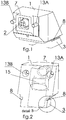
- Fig. 1 presents a front axonometric view of the plug body
- Fig. 2 presents a rear view of the plug body
- Fig. 3 presents the centering element
- Fig. 4 presents the plug body connected to the centering element
- Fig. 5 presents the plug body connected to the centering element
- Fig. 5 presents a block diagram of an example arrangement of the interior of an assembly compartment
- Fig. 10 presents an axonometric view of the track with a track sensor installed with a cable using a plug according to the invention connected to the sensor.
- the through body 1 and the base 3 are provided with a plug socket 2.
- a frame protrusion 7 is formed in the front wall of the body 1 and first, parallel guides 9 are provided on both sides of base 3.
- body 1 is placed in a detachable manner on the centering element 3 presented in Fig. 3 in the form of an angled profile made of a load-bearing plate 5 and an adjusting plate 6 placed perpendicular to the load-bearing plate.
- a semi-circular cable conduit 10 is formed in the middle of the load-bearing plate 5, on the side of the body 1.
- Second parallel guides 9 are formed on both sides of the cable conduit 10.
- An adjusting cut-out 11 is made in the adjusting plate 6, with a shape adapted to the frame protrusion 7.
- a sliding depression 12 is formed in the load-bearing plate 5, with its shape adapted to base 3 of the body 1.
- Two parallel, longitudinal openings 14 are provided in the load-bearing plate 5, on both sides of the sliding depression 12.
- body 1 When the plug is connected to the track sensor, body 1 is inserted onto the resting guides 9 formed in the load-bearing plate 5 using starter guides 8, while the frame protrusion 7 is pressed into the adjusting cut-out 11 in the load-bearing plate 6.
- the load-bearing plate 6 of the centering element 4 is connected with the body 1 using two screws 13A and 13B.
- starter guides 8 are provided as battens
- resting gides 9 are provided as ducts.
- Fig. 10 presents the plug in its working position.
- a track sensor with a plug socket inside a housing O is installed on track S.
- a plug centering element W is attached to the housing O using two screws P.
- the plug W provided with a plug socket 2 is installed on a fixing element M using screw connections placed in longitudinal openings 14A and 14B.
- the fixing element M is attached to the track S. Cable K placed inside a rubber screen is connected to the plug W.
- the plug is provided as in Example 1 with the exception that starter guides 8 are provided as ducts and resting guides 9 are provided as battens, as shown in Fig. 7 .
- external environment monitoring sensors 19 are installed in the internal assembly compartment 15 placed inside the body 1 and connected to an additional connector 16 installed in the plug socket 2 next to the main connector 17.
- External environment monitoring sensors 19 include overvoltage protectors and sensors of various types, installed according to local needs.
Landscapes
- Engineering & Computer Science (AREA)
- Architecture (AREA)
- Civil Engineering (AREA)
- Structural Engineering (AREA)
- Automation & Control Theory (AREA)
- Mechanical Engineering (AREA)
- Details Of Connecting Devices For Male And Female Coupling (AREA)
Priority Applications (1)
| Application Number | Priority Date | Filing Date | Title |
|---|---|---|---|
| RS20210840A RS62065B1 (sr) | 2018-05-08 | 2018-07-19 | Uređaj za ugradnju senzora koloseka |
Applications Claiming Priority (1)
| Application Number | Priority Date | Filing Date | Title |
|---|---|---|---|
| PL425461A PL234683B1 (pl) | 2018-05-08 | 2018-05-08 | Wtyczka do mocowania przyłączy kablowych czujników torowych |
Publications (2)
| Publication Number | Publication Date |
|---|---|
| EP3567161A1 true EP3567161A1 (de) | 2019-11-13 |
| EP3567161B1 EP3567161B1 (de) | 2021-04-07 |
Family
ID=64331993
Family Applications (1)
| Application Number | Title | Priority Date | Filing Date |
|---|---|---|---|
| EP18460045.0A Active EP3567161B1 (de) | 2018-05-08 | 2018-07-19 | Vorrichtung zur installation von gleissensoren |
Country Status (4)
| Country | Link |
|---|---|
| EP (1) | EP3567161B1 (de) |
| ES (1) | ES2880254T3 (de) |
| PL (1) | PL234683B1 (de) |
| RS (1) | RS62065B1 (de) |
Cited By (4)
| Publication number | Priority date | Publication date | Assignee | Title |
|---|---|---|---|---|
| EP3620346B1 (de) | 2018-09-06 | 2021-01-13 | Frauscher Sensortechnik GmbH | Sensoranordnung |
| RU206432U1 (ru) * | 2020-01-20 | 2021-09-13 | Акционерное Общество "Научно-Производственный Центр "Промэлектроника" | Устройство для крепления рельсового датчика на рельсах |
| RU2766622C1 (ru) * | 2021-10-12 | 2022-03-15 | Ренат Мазгарович Шарипов | Устройство для крепления путевого датчика к рельсу |
| KR102426835B1 (ko) * | 2022-04-05 | 2022-07-29 | (주)중흥테크놀러지 | 차축 카운터 센서 고정장치 |
Families Citing this family (1)
| Publication number | Priority date | Publication date | Assignee | Title |
|---|---|---|---|---|
| PL245120B1 (pl) | 2021-09-10 | 2024-05-20 | Voestalpine Signaling Poland Spółka Z Ograniczoną Odpowiedzialnością | Układ czujnika torowego |
Citations (6)
| Publication number | Priority date | Publication date | Assignee | Title |
|---|---|---|---|---|
| US20050072252A1 (en) * | 2003-10-03 | 2005-04-07 | Sudhir Kumar | Wheel sensor assembly for rail base mounting |
| EP1808531B1 (de) | 2005-12-14 | 2009-01-07 | Frauscher Holding GmbH | Vorrichtung zur Anbringung von Sensoren bzw. Schaltmitteln in Gleisanlagen |
| ES2319062A1 (es) * | 2007-09-19 | 2009-05-01 | Linea Y Cables, S.A. | Pedal ferroviario. |
| CN107191446A (zh) * | 2017-06-27 | 2017-09-22 | 北京康拓红外技术股份有限公司 | 一种应用于车辆运行安全监控系统的磁钢卡轨器 |
| CN206902483U (zh) * | 2017-05-22 | 2018-01-19 | 广州地铁集团有限公司 | 一种用于安装轨道传感器的夹具 |
| DE102017103243B3 (de) * | 2017-02-16 | 2018-02-22 | Zöllner Signal GmbH | Halterung für Zugdetektor zur werkzeuglosen Montage |
-
2018
- 2018-05-08 PL PL425461A patent/PL234683B1/pl unknown
- 2018-07-19 RS RS20210840A patent/RS62065B1/sr unknown
- 2018-07-19 EP EP18460045.0A patent/EP3567161B1/de active Active
- 2018-07-19 ES ES18460045T patent/ES2880254T3/es active Active
Patent Citations (6)
| Publication number | Priority date | Publication date | Assignee | Title |
|---|---|---|---|---|
| US20050072252A1 (en) * | 2003-10-03 | 2005-04-07 | Sudhir Kumar | Wheel sensor assembly for rail base mounting |
| EP1808531B1 (de) | 2005-12-14 | 2009-01-07 | Frauscher Holding GmbH | Vorrichtung zur Anbringung von Sensoren bzw. Schaltmitteln in Gleisanlagen |
| ES2319062A1 (es) * | 2007-09-19 | 2009-05-01 | Linea Y Cables, S.A. | Pedal ferroviario. |
| DE102017103243B3 (de) * | 2017-02-16 | 2018-02-22 | Zöllner Signal GmbH | Halterung für Zugdetektor zur werkzeuglosen Montage |
| CN206902483U (zh) * | 2017-05-22 | 2018-01-19 | 广州地铁集团有限公司 | 一种用于安装轨道传感器的夹具 |
| CN107191446A (zh) * | 2017-06-27 | 2017-09-22 | 北京康拓红外技术股份有限公司 | 一种应用于车辆运行安全监控系统的磁钢卡轨器 |
Cited By (5)
| Publication number | Priority date | Publication date | Assignee | Title |
|---|---|---|---|---|
| EP3620346B1 (de) | 2018-09-06 | 2021-01-13 | Frauscher Sensortechnik GmbH | Sensoranordnung |
| US20210347395A1 (en) * | 2018-09-06 | 2021-11-11 | Frauscher Sensortechnik GmbH | Sensor arrangement |
| RU206432U1 (ru) * | 2020-01-20 | 2021-09-13 | Акционерное Общество "Научно-Производственный Центр "Промэлектроника" | Устройство для крепления рельсового датчика на рельсах |
| RU2766622C1 (ru) * | 2021-10-12 | 2022-03-15 | Ренат Мазгарович Шарипов | Устройство для крепления путевого датчика к рельсу |
| KR102426835B1 (ko) * | 2022-04-05 | 2022-07-29 | (주)중흥테크놀러지 | 차축 카운터 센서 고정장치 |
Also Published As
| Publication number | Publication date |
|---|---|
| RS62065B1 (sr) | 2021-07-30 |
| PL425461A1 (pl) | 2019-11-18 |
| PL234683B1 (pl) | 2020-03-31 |
| ES2880254T3 (es) | 2021-11-24 |
| EP3567161B1 (de) | 2021-04-07 |
Similar Documents
| Publication | Publication Date | Title |
|---|---|---|
| EP3567161B1 (de) | Vorrichtung zur installation von gleissensoren | |
| BR112016028302A2 (pt) | backplane e dispositivo de comunicações | |
| US4928530A (en) | Pressure transducer | |
| MX2022003227A (es) | Conector de enchufe electrico. | |
| CA2290927C (en) | Transmitter housing | |
| EP3109954A1 (de) | Stimmensplitter | |
| US20080097718A1 (en) | Interfacing apparatus and method for mounting sensors on the same | |
| CN102951102A (zh) | 一种线束连接安装结构 | |
| JP2014106952A (ja) | プログラマブルコントロールユニットの配線変換装置 | |
| CN110120609B (zh) | 在插接连接器壳体中的线缆减轻张力和屏蔽附接 | |
| US10928264B2 (en) | Sensor assembly and liquid level detection device | |
| JP7196065B2 (ja) | 電圧インジケータ表示モジュール | |
| RU2541507C2 (ru) | Система соединения однорядного корпуса с соединительным элементом | |
| CN214204191U (zh) | 地址模块机箱 | |
| US20190353510A1 (en) | Electronics unit for a flow meter | |
| US6354857B1 (en) | Transmitter housing | |
| ITPD20120373A1 (it) | Trasduttore di pressione | |
| US9288926B2 (en) | Structure for holding electric/electronic component with electric wire | |
| EP3000663B1 (de) | System zur erfassung und überwachung elektrischer und pneumatischer signale aus lüftungseinrichtungen | |
| EP3591905B1 (de) | Kommunikationseinheit und sicherheitssystem | |
| DE20215283U1 (de) | Baugruppe eines Kraftfahrzeugs | |
| JP6576572B2 (ja) | 流量測定器用の駆動兼制御装置 | |
| KR20070002938A (ko) | 차량 도어 그로멧의 체결 감지 장치 | |
| AU2011205067B2 (en) | An External Power Point Arrangement | |
| CN116918184A (zh) | 接地连接端子 |
Legal Events
| Date | Code | Title | Description |
|---|---|---|---|
| PUAI | Public reference made under article 153(3) epc to a published international application that has entered the european phase |
Free format text: ORIGINAL CODE: 0009012 |
|
| STAA | Information on the status of an ep patent application or granted ep patent |
Free format text: STATUS: THE APPLICATION HAS BEEN PUBLISHED |
|
| AK | Designated contracting states |
Kind code of ref document: A1 Designated state(s): AL AT BE BG CH CY CZ DE DK EE ES FI FR GB GR HR HU IE IS IT LI LT LU LV MC MK MT NL NO PL PT RO RS SE SI SK SM TR |
|
| AX | Request for extension of the european patent |
Extension state: BA ME |
|
| STAA | Information on the status of an ep patent application or granted ep patent |
Free format text: STATUS: REQUEST FOR EXAMINATION WAS MADE |
|
| 17P | Request for examination filed |
Effective date: 20200513 |
|
| RAP1 | Party data changed (applicant data changed or rights of an application transferred) |
Owner name: VOESTALPINE SIGNALING POLAND SP. Z O.O. |
|
| RBV | Designated contracting states (corrected) |
Designated state(s): AL AT BE BG CH CY CZ DE DK EE ES FI FR GB GR HR HU IE IS IT LI LT LU LV MC MK MT NL NO PL PT RO RS SE SI SK SM TR |
|
| GRAP | Despatch of communication of intention to grant a patent |
Free format text: ORIGINAL CODE: EPIDOSNIGR1 |
|
| STAA | Information on the status of an ep patent application or granted ep patent |
Free format text: STATUS: GRANT OF PATENT IS INTENDED |
|
| GRAS | Grant fee paid |
Free format text: ORIGINAL CODE: EPIDOSNIGR3 |
|
| INTG | Intention to grant announced |
Effective date: 20210201 |
|
| GRAA | (expected) grant |
Free format text: ORIGINAL CODE: 0009210 |
|
| STAA | Information on the status of an ep patent application or granted ep patent |
Free format text: STATUS: THE PATENT HAS BEEN GRANTED |
|
| AK | Designated contracting states |
Kind code of ref document: B1 Designated state(s): AL AT BE BG CH CY CZ DE DK EE ES FI FR GB GR HR HU IE IS IT LI LT LU LV MC MK MT NL NO PL PT RO RS SE SI SK SM TR |
|
| REG | Reference to a national code |
Ref country code: GB Ref legal event code: FG4D |
|
| REG | Reference to a national code |
Ref country code: AT Ref legal event code: REF Ref document number: 1379835 Country of ref document: AT Kind code of ref document: T Effective date: 20210415 Ref country code: CH Ref legal event code: EP |
|
| REG | Reference to a national code |
Ref country code: DE Ref legal event code: R096 Ref document number: 602018015128 Country of ref document: DE |
|
| REG | Reference to a national code |
Ref country code: IE Ref legal event code: FG4D |
|
| REG | Reference to a national code |
Ref country code: LT Ref legal event code: MG9D |
|
| REG | Reference to a national code |
Ref country code: NO Ref legal event code: T2 Effective date: 20210407 |
|
| REG | Reference to a national code |
Ref country code: NL Ref legal event code: MP Effective date: 20210407 Ref country code: AT Ref legal event code: MK05 Ref document number: 1379835 Country of ref document: AT Kind code of ref document: T Effective date: 20210407 |
|
| PG25 | Lapsed in a contracting state [announced via postgrant information from national office to epo] |
Ref country code: NL Free format text: LAPSE BECAUSE OF FAILURE TO SUBMIT A TRANSLATION OF THE DESCRIPTION OR TO PAY THE FEE WITHIN THE PRESCRIBED TIME-LIMIT Effective date: 20210407 Ref country code: BG Free format text: LAPSE BECAUSE OF FAILURE TO SUBMIT A TRANSLATION OF THE DESCRIPTION OR TO PAY THE FEE WITHIN THE PRESCRIBED TIME-LIMIT Effective date: 20210707 Ref country code: AT Free format text: LAPSE BECAUSE OF FAILURE TO SUBMIT A TRANSLATION OF THE DESCRIPTION OR TO PAY THE FEE WITHIN THE PRESCRIBED TIME-LIMIT Effective date: 20210407 Ref country code: FI Free format text: LAPSE BECAUSE OF FAILURE TO SUBMIT A TRANSLATION OF THE DESCRIPTION OR TO PAY THE FEE WITHIN THE PRESCRIBED TIME-LIMIT Effective date: 20210407 Ref country code: HR Free format text: LAPSE BECAUSE OF FAILURE TO SUBMIT A TRANSLATION OF THE DESCRIPTION OR TO PAY THE FEE WITHIN THE PRESCRIBED TIME-LIMIT Effective date: 20210407 Ref country code: LT Free format text: LAPSE BECAUSE OF FAILURE TO SUBMIT A TRANSLATION OF THE DESCRIPTION OR TO PAY THE FEE WITHIN THE PRESCRIBED TIME-LIMIT Effective date: 20210407 |
|
| REG | Reference to a national code |
Ref country code: ES Ref legal event code: FG2A Ref document number: 2880254 Country of ref document: ES Kind code of ref document: T3 Effective date: 20211124 |
|
| PG25 | Lapsed in a contracting state [announced via postgrant information from national office to epo] |
Ref country code: GR Free format text: LAPSE BECAUSE OF FAILURE TO SUBMIT A TRANSLATION OF THE DESCRIPTION OR TO PAY THE FEE WITHIN THE PRESCRIBED TIME-LIMIT Effective date: 20210708 Ref country code: IS Free format text: LAPSE BECAUSE OF FAILURE TO SUBMIT A TRANSLATION OF THE DESCRIPTION OR TO PAY THE FEE WITHIN THE PRESCRIBED TIME-LIMIT Effective date: 20210807 Ref country code: PT Free format text: LAPSE BECAUSE OF FAILURE TO SUBMIT A TRANSLATION OF THE DESCRIPTION OR TO PAY THE FEE WITHIN THE PRESCRIBED TIME-LIMIT Effective date: 20210809 Ref country code: LV Free format text: LAPSE BECAUSE OF FAILURE TO SUBMIT A TRANSLATION OF THE DESCRIPTION OR TO PAY THE FEE WITHIN THE PRESCRIBED TIME-LIMIT Effective date: 20210407 Ref country code: PL Free format text: LAPSE BECAUSE OF FAILURE TO SUBMIT A TRANSLATION OF THE DESCRIPTION OR TO PAY THE FEE WITHIN THE PRESCRIBED TIME-LIMIT Effective date: 20210407 Ref country code: SE Free format text: LAPSE BECAUSE OF FAILURE TO SUBMIT A TRANSLATION OF THE DESCRIPTION OR TO PAY THE FEE WITHIN THE PRESCRIBED TIME-LIMIT Effective date: 20210407 |
|
| REG | Reference to a national code |
Ref country code: DE Ref legal event code: R097 Ref document number: 602018015128 Country of ref document: DE |
|
| PG25 | Lapsed in a contracting state [announced via postgrant information from national office to epo] |
Ref country code: EE Free format text: LAPSE BECAUSE OF FAILURE TO SUBMIT A TRANSLATION OF THE DESCRIPTION OR TO PAY THE FEE WITHIN THE PRESCRIBED TIME-LIMIT Effective date: 20210407 Ref country code: SK Free format text: LAPSE BECAUSE OF FAILURE TO SUBMIT A TRANSLATION OF THE DESCRIPTION OR TO PAY THE FEE WITHIN THE PRESCRIBED TIME-LIMIT Effective date: 20210407 Ref country code: SM Free format text: LAPSE BECAUSE OF FAILURE TO SUBMIT A TRANSLATION OF THE DESCRIPTION OR TO PAY THE FEE WITHIN THE PRESCRIBED TIME-LIMIT Effective date: 20210407 Ref country code: RO Free format text: LAPSE BECAUSE OF FAILURE TO SUBMIT A TRANSLATION OF THE DESCRIPTION OR TO PAY THE FEE WITHIN THE PRESCRIBED TIME-LIMIT Effective date: 20210407 Ref country code: DK Free format text: LAPSE BECAUSE OF FAILURE TO SUBMIT A TRANSLATION OF THE DESCRIPTION OR TO PAY THE FEE WITHIN THE PRESCRIBED TIME-LIMIT Effective date: 20210407 |
|
| PLBE | No opposition filed within time limit |
Free format text: ORIGINAL CODE: 0009261 |
|
| STAA | Information on the status of an ep patent application or granted ep patent |
Free format text: STATUS: NO OPPOSITION FILED WITHIN TIME LIMIT |
|
| REG | Reference to a national code |
Ref country code: CH Ref legal event code: PL |
|
| 26N | No opposition filed |
Effective date: 20220110 |
|
| PG25 | Lapsed in a contracting state [announced via postgrant information from national office to epo] |
Ref country code: MC Free format text: LAPSE BECAUSE OF FAILURE TO SUBMIT A TRANSLATION OF THE DESCRIPTION OR TO PAY THE FEE WITHIN THE PRESCRIBED TIME-LIMIT Effective date: 20210407 |
|
| PG25 | Lapsed in a contracting state [announced via postgrant information from national office to epo] |
Ref country code: LI Free format text: LAPSE BECAUSE OF NON-PAYMENT OF DUE FEES Effective date: 20210731 Ref country code: CH Free format text: LAPSE BECAUSE OF NON-PAYMENT OF DUE FEES Effective date: 20210731 |
|
| PG25 | Lapsed in a contracting state [announced via postgrant information from national office to epo] |
Ref country code: IS Free format text: LAPSE BECAUSE OF FAILURE TO SUBMIT A TRANSLATION OF THE DESCRIPTION OR TO PAY THE FEE WITHIN THE PRESCRIBED TIME-LIMIT Effective date: 20210807 Ref country code: LU Free format text: LAPSE BECAUSE OF NON-PAYMENT OF DUE FEES Effective date: 20210719 Ref country code: AL Free format text: LAPSE BECAUSE OF FAILURE TO SUBMIT A TRANSLATION OF THE DESCRIPTION OR TO PAY THE FEE WITHIN THE PRESCRIBED TIME-LIMIT Effective date: 20210407 |
|
| PG25 | Lapsed in a contracting state [announced via postgrant information from national office to epo] |
Ref country code: IE Free format text: LAPSE BECAUSE OF NON-PAYMENT OF DUE FEES Effective date: 20210719 |
|
| PG25 | Lapsed in a contracting state [announced via postgrant information from national office to epo] |
Ref country code: CY Free format text: LAPSE BECAUSE OF FAILURE TO SUBMIT A TRANSLATION OF THE DESCRIPTION OR TO PAY THE FEE WITHIN THE PRESCRIBED TIME-LIMIT Effective date: 20210407 |
|
| P01 | Opt-out of the competence of the unified patent court (upc) registered |
Effective date: 20230526 |
|
| PG25 | Lapsed in a contracting state [announced via postgrant information from national office to epo] |
Ref country code: HU Free format text: LAPSE BECAUSE OF FAILURE TO SUBMIT A TRANSLATION OF THE DESCRIPTION OR TO PAY THE FEE WITHIN THE PRESCRIBED TIME-LIMIT; INVALID AB INITIO Effective date: 20180719 |
|
| PGFP | Annual fee paid to national office [announced via postgrant information from national office to epo] |
Ref country code: TR Payment date: 20230717 Year of fee payment: 6 Ref country code: NO Payment date: 20230721 Year of fee payment: 6 Ref country code: IT Payment date: 20230724 Year of fee payment: 6 Ref country code: GB Payment date: 20230721 Year of fee payment: 6 Ref country code: ES Payment date: 20230927 Year of fee payment: 6 Ref country code: CZ Payment date: 20230711 Year of fee payment: 6 |
|
| PGFP | Annual fee paid to national office [announced via postgrant information from national office to epo] |
Ref country code: RS Payment date: 20230706 Year of fee payment: 6 Ref country code: FR Payment date: 20230726 Year of fee payment: 6 Ref country code: DE Payment date: 20230719 Year of fee payment: 6 Ref country code: BE Payment date: 20230719 Year of fee payment: 6 |
|
| PG25 | Lapsed in a contracting state [announced via postgrant information from national office to epo] |
Ref country code: MK Free format text: LAPSE BECAUSE OF FAILURE TO SUBMIT A TRANSLATION OF THE DESCRIPTION OR TO PAY THE FEE WITHIN THE PRESCRIBED TIME-LIMIT Effective date: 20210407 |