EP3566657A1 - Vorrichtung und verfahren zum ablängen von chirurgischem nahtmaterial - Google Patents
Vorrichtung und verfahren zum ablängen von chirurgischem nahtmaterial Download PDFInfo
- Publication number
- EP3566657A1 EP3566657A1 EP18171314.0A EP18171314A EP3566657A1 EP 3566657 A1 EP3566657 A1 EP 3566657A1 EP 18171314 A EP18171314 A EP 18171314A EP 3566657 A1 EP3566657 A1 EP 3566657A1
- Authority
- EP
- European Patent Office
- Prior art keywords
- thread
- surgical suture
- deflection
- cutting
- length
- Prior art date
- Legal status (The legal status is an assumption and is not a legal conclusion. Google has not performed a legal analysis and makes no representation as to the accuracy of the status listed.)
- Granted
Links
Images


Classifications
-
- B—PERFORMING OPERATIONS; TRANSPORTING
- B26—HAND CUTTING TOOLS; CUTTING; SEVERING
- B26D—CUTTING; DETAILS COMMON TO MACHINES FOR PERFORATING, PUNCHING, CUTTING-OUT, STAMPING-OUT OR SEVERING
- B26D5/00—Arrangements for operating and controlling machines or devices for cutting, cutting-out, stamping-out, punching, perforating, or severing by means other than cutting
- B26D5/20—Arrangements for operating and controlling machines or devices for cutting, cutting-out, stamping-out, punching, perforating, or severing by means other than cutting with interrelated action between the cutting member and work feed
- B26D5/22—Arrangements for operating and controlling machines or devices for cutting, cutting-out, stamping-out, punching, perforating, or severing by means other than cutting with interrelated action between the cutting member and work feed having the cutting member and work feed mechanically connected
- B26D5/24—Arrangements for operating and controlling machines or devices for cutting, cutting-out, stamping-out, punching, perforating, or severing by means other than cutting with interrelated action between the cutting member and work feed having the cutting member and work feed mechanically connected including a metering device
-
- A—HUMAN NECESSITIES
- A61—MEDICAL OR VETERINARY SCIENCE; HYGIENE
- A61B—DIAGNOSIS; SURGERY; IDENTIFICATION
- A61B17/00—Surgical instruments, devices or methods
- A61B17/04—Surgical instruments, devices or methods for suturing wounds; Holders or packages for needles or suture materials
- A61B17/0467—Instruments for cutting sutures
-
- B—PERFORMING OPERATIONS; TRANSPORTING
- B65—CONVEYING; PACKING; STORING; HANDLING THIN OR FILAMENTARY MATERIAL
- B65H—HANDLING THIN OR FILAMENTARY MATERIAL, e.g. SHEETS, WEBS, CABLES
- B65H54/00—Winding, coiling, or depositing filamentary material
- B65H54/70—Other constructional features of yarn-winding machines
- B65H54/71—Arrangements for severing filamentary materials
-
- A—HUMAN NECESSITIES
- A61—MEDICAL OR VETERINARY SCIENCE; HYGIENE
- A61B—DIAGNOSIS; SURGERY; IDENTIFICATION
- A61B17/00—Surgical instruments, devices or methods
- A61B17/04—Surgical instruments, devices or methods for suturing wounds; Holders or packages for needles or suture materials
- A61B17/06—Needles ; Sutures; Needle-suture combinations; Holders or packages for needles or suture materials
- A61B17/06004—Means for attaching suture to needle
-
- A—HUMAN NECESSITIES
- A61—MEDICAL OR VETERINARY SCIENCE; HYGIENE
- A61B—DIAGNOSIS; SURGERY; IDENTIFICATION
- A61B17/00—Surgical instruments, devices or methods
- A61B17/04—Surgical instruments, devices or methods for suturing wounds; Holders or packages for needles or suture materials
- A61B17/06—Needles ; Sutures; Needle-suture combinations; Holders or packages for needles or suture materials
- A61B17/06166—Sutures
-
- A—HUMAN NECESSITIES
- A61—MEDICAL OR VETERINARY SCIENCE; HYGIENE
- A61B—DIAGNOSIS; SURGERY; IDENTIFICATION
- A61B17/00—Surgical instruments, devices or methods
- A61B2017/00526—Methods of manufacturing
-
- A—HUMAN NECESSITIES
- A61—MEDICAL OR VETERINARY SCIENCE; HYGIENE
- A61B—DIAGNOSIS; SURGERY; IDENTIFICATION
- A61B90/00—Instruments, implements or accessories specially adapted for surgery or diagnosis and not covered by any of the groups A61B1/00 - A61B50/00, e.g. for luxation treatment or for protecting wound edges
- A61B90/06—Measuring instruments not otherwise provided for
- A61B2090/061—Measuring instruments not otherwise provided for for measuring dimensions, e.g. length
-
- B—PERFORMING OPERATIONS; TRANSPORTING
- B26—HAND CUTTING TOOLS; CUTTING; SEVERING
- B26D—CUTTING; DETAILS COMMON TO MACHINES FOR PERFORATING, PUNCHING, CUTTING-OUT, STAMPING-OUT OR SEVERING
- B26D7/00—Details of apparatus for cutting, cutting-out, stamping-out, punching, perforating, or severing by means other than cutting
- B26D7/08—Means for treating work or cutting member to facilitate cutting
- B26D7/10—Means for treating work or cutting member to facilitate cutting by heating
Definitions
- the invention relates to an apparatus and method for cutting surgical sutures to reproducibly position the beginning of a surgical suture strand and flexibly bring it to a defined cut-off length.
- an endless thread of suture material is thus shortened to a desired length.
- the surgical suture can be attached to a surgical needle or be present as a loose thread.
- Devices for cutting surgical sutures are known. They usually have a thread roll with a continuous thread of surgical suture. By means of a linear preferred in a (horizontal or vertical) transport direction yarn preferred gripper, the desired length of surgical suture is withdrawn from the thread roll. This removal from the thread roll is partially controlled by a so-called dancer. Subsequently, the surgical suture is cut at the desired location by means of a cutting unit.
- the leading suture end of the surgical suture must be pulled forward to a fixed position because the connection of the anterior suture end to the suture needle can only occur at that defined position.
- An adaptation of this joining position to different thread lengths is not technically possible. Therefore, the rule is always the maximum possible length of suture material before free suture length.
- the adaptation of the device to different thread lengths is then carried out by a displacement of the cutting unit in the longitudinal direction of the free thread.
- the travel range of the thread-preferred gripper is adapted with regard to its starting position.
- the surgical suture is then cut at a certain distance from the thread roller.
- Such cutting machines build accordingly long.
- the free thread length is relatively large, so that it can lead to significant vibrations in the area of the unrolled surgical suture. This can complicate both the threading of the thread into the needle and the actual cutting of the thread.
- the present invention seeks to provide an improved device for cutting surgical suture material to different lengths of thread that allows the most compact design possible.
- the inventive device for cutting surgical suture is given by the features of the main claim 1.
- the inventive method is given by the features of the independent claim 7.
- the surgical suture cutting device of the present invention has a suture roll with an endless suture of the surgical suture and a suture gripper for withdrawing a defined length of surgical suture.
- a cutting unit for cutting the surgical suture is present.
- a deflection device is provided, through which the surgical suture material along a secondary axis at an angle to the primary transport direction can be placed in at least one open loop. The length of this open loop can be variably adjusted.
- the cutting unit is positioned between the deflecting device and the thread roller for the endless thread.
- the deflection device Due to the presence of the deflection device, it is no longer necessary to make the cutting unit displaceable in the longitudinal direction. Rather, it allows the diverter to unroll and cut different lengths of surgical suture.
- the different lengths are determined by the length of the open loop.
- the free thread length of the surgical suture therefore no longer has to correspond to the maximum possible thread length, but only to the minimum required thread length. In this way, the device can be reduced to about one third of the previously required length.
- the device according to the invention can therefore be significantly shorter and thus also significantly more compact.
- the surgical suture can be placed by the deflecting device perpendicular to the primary transport direction in at least one open loop.
- the open loop can therefore be optimally integrated into the device, so that it can build compact.
- the deflection device may have a front and a rear deflection unit, which are each designed to be stationary. Between the two stationary deflection units, one or more movable compensating rollers may be present.
- the at least one compensating roller determines the loop length of the surgical suture by the length of its travel.
- the travel of the compensating roller surgical suture.
- the travel of the compensating roller can in particular be input to a control unit, so that in the apparatus according to the invention a simple and precise adjustment of the desired thread length is possible.
- the front deflection unit can preferably be designed as a stationary thread deflection.
- further surgical suture material is withdrawn via the rear deflection unit as soon as the compensating roller is moved from its initial position.
- the rear deflection unit may therefore preferably be designed as a stationary deflection roller.
- the deflection device can be designed to be height-adjustable in an advantageous embodiment. Since the cutting of the surgical suture always takes place behind the deflection device as seen in the transport direction, the thread-preferred gripper has to pass the point of the deflection device in order to transport the new front thread end forward again. If the deflection device is designed to be height-adjustable, the individual components of the deflection device can move upwards or downwards in order to make room for the thread-preferred gripper. The thread-preferred gripper can be moved faster in particular on the way to the new front end of the thread, moreover, the thread of the surgical suture is thereby spared.
- the thread-preferred gripper can describe an arc around the deflecting device during retraction without transport of the surgical suture material and / or during ancestral transport of the surgical suture material.
- the thread-preferred gripper could therefore pass, for example, laterally or above the deflection device.
- the surgical suture is first withdrawn from a thread roll with an endless thread by means of a thread-preferred gripper.
- the thread-preferred gripper advances to a predetermined end position.
- the surgical suture is placed by a deflecting device in at least one open loop running at an angle to the primary transport direction of the withdrawn surgical suture.
- a deflecting device in at least one open loop running at an angle to the primary transport direction of the withdrawn surgical suture.
- further surgical suture material is withdrawn from the thread roll without the thread-preferred gripper moving on.
- the withdrawn from the thread roll surgical suture is cut by a cutting unit.
- the cutting unit is positioned between the thread roller and the deflection.
- the cutting unit is located in the vicinity of the deflection.
- the rear end of the thread can fall down after the severing of the endless thread by the deflection device and does not remain completely on the deflection device. This facilitates the further transport of the cut pieces of thread.
- the travel path of the thread-preferred gripper is always identical regardless of the length of the actually cut surgical suture.
- the travel can be chosen relatively short, so that this process step correspondingly requires little time.
- the front thread end is already fixed in position, so that further processing steps can be carried out on the front thread end.
- the thread-preferred gripper can travel to a joint for connecting the surgical suture with a corresponding needle. In this case, a fixation of the front end of the surgical suture in the needle can already take place during the further removal of the surgical suture.
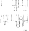
- a first embodiment of the inventive device 10 for cutting suture material 12 is in the Fig. 1 to 3 shown schematically.
- the device 10 has a thread roller 20 with an endless thread of the surgical suture material 12. From this thread roller 20, the surgical suture 12 can be withdrawn by means of a thread preferred gripper 22. For this purpose, the thread-preferred gripper 22 advances to a defined end position 24.
- the thread roller 20 rotates about its axis 26 and the surgical suture 12 is rolled in the present example in the horizontal direction (primary transport direction 14).
- a connection of the front end of the surgical suture 12 with a needle takes place.
- the front end of the surgical suture 12 is inserted a little way into the hollow end of the needle.
- the hollow end of the needle is compressed to fix the surgical suture 12 in the needle.
- the process of attaching the surgical suture 12 into the needle immediately after reaching the end position 24 may be started.
- a deflection device 30 is present between the thread roller 20 and the end position 24, a deflection device 30 is present.
- a single movable compensating roller 34 is present behind the stationary thread deflection 32.
- Behind a stationary deflection roller 36 is arranged.
- the surgical suture 12 is guided above the stationary thread deflection 32 and the stationary deflection roller 36; on the other hand, the surgical suture 12 is below the traveling compensating roller 34.
- a process of the balancing roller 34 see FIG Fig. 2
- further surgical suture 12 are withdrawn from the thread roll 20.
- a longer piece of surgical suture material 12 can be cut off without the thread-preferred gripper 22 having to be moved further.
- the surgical suture 12 is placed in an approximately U-shaped open loop 40.
- the length of the loop 40 is determined by the travel distance of the compensating roller 34. This travel distance can be input individually to a control unit of the device 10. Thereby, the total length of the cut surgical suture 12 can be easily varied and adapted to different needs.
- the surgical suture 12 can be cut.
- a cutting unit 50 is arranged between the deflection device 30 and the thread roller 20.
- the cutting unit 50 has in the present example an upper cutting blade 52 and a lower cutting blade 54.
- the cutting unit 50 is stationary aligned, since an adjustment of the suture length of the surgical suture 12 can be done by the deflecting device 30. This simplifies the structural design of the cutting unit 50 and thus also of the device 10.
- the cutting unit may comprise a single cutting blade which may be disposed laterally of the surgical suture 12. Due to the tension in the thread, a single cutting knife can be sufficient to ensure a clean and precise cut.
- the design of the cutting unit is basically irrelevant in this context for the invention.
- the suture back end of the surgical suture 12 must again be held by the suture gripper 22.
- the thread-preferred gripper 22 is retracted after fixing the front end of the surgical suture 12 in the needle back to its original position behind the cutting unit 50 (see Fig. 3 ).
- a second, rear suture gripper may also be employed to fix the anterior suture end of the subsequent surgical suture 12.
- This rear thread gripper may be provided stationarily immediately behind the cutting unit 50. After cutting the thread, the actual thread-preferred gripper 22 can then release the front thread end and retract to take over the subsequent front thread end of the rear thread gripper.
- FIG. 5 A second embodiment of the device 10.2 according to the invention with such a dancer 60 for removing the surgical suture 12 from a thread roll 20 is in Fig. 5 shown schematically.
- the dancer 60 is adjustable in height and can be moved with a fixed thread-preferred gripper, to withdraw additional surgical suture 12 from the thread roll 20. If the thread-preferred gripper is then moved with the front end of the thread, the dancer 60 is again successively returned to its starting position in order to release the correspondingly required thread length.
- the dancer 60 is regularly arranged between the cutting unit 50 and the thread roller 20 with the endless thread; Ideally, the dancer 60 is in the immediate vicinity of the thread roll 20th
- the surgical suture 12 may be fused at the later interface by means of a heating element 62.
- the heating element 62 is arranged between the dancer 60 and the cutting unit 50. Basically, the surgical suture is not welded over the entire length of the thread, but only at the later interface. For this purpose, a whole multiple of the desired suture length of the surgical suture material 12 must run between the cutting unit 50 and the heating element 62.
- the heating element 62 was therefore regularly designed as well as the cutting unit 50 adjustable.
- a movable guide roller 64 is formed between the heating element 62 and the cutting unit, by which a compensation of the thread length can be done. In this way, the heating element 62 may be formed stationary.
- a third embodiment of the inventive device 10.3 for cutting suture material 12 is in the Fig. 6 to 8 shown schematically.
- the device 10.3, like the device 10, has a thread roller 20 with an endless thread of the surgical suture 12 and a thread-preferred gripper 22.
- the deflection device 30.3 has in the present embodiment, a stationary thread deflection 32nd
- a first movable compensating roller 34 and a second movable compensating roller 38 is present. Behind a stationary deflection roller 36 is arranged.
- the surgical suture 12 is guided above the stationary suture deflector 32 and the second balancing roller 38; on the other hand, the surgical suture material 12 is below the first movable compensating roller 34 and the stationary deflecting roller 36.
- the two balancing rollers 34, 38 can be as in FIGS. 7 and 8 be shown simultaneously. Alternatively, it would also be possible to first only one of the two balancing rollers 34, 38 to proceed. Only when the maximum travel of this compensating roller 34, 38 is reached, the process of the other balancing roller 34, 38 would be started.
- the surgical suture 12 is placed in two open loops 40.3, 42.
- the length of the two open loops 40.3, 42 is determined by the travel distance of the corresponding compensating roller 34, 38. Thereby, the total length of the cut surgical suture 12 can be easily varied and adapted to different needs.
Landscapes
- Health & Medical Sciences (AREA)
- Life Sciences & Earth Sciences (AREA)
- Surgery (AREA)
- Engineering & Computer Science (AREA)
- Molecular Biology (AREA)
- Public Health (AREA)
- Heart & Thoracic Surgery (AREA)
- Medical Informatics (AREA)
- Nuclear Medicine, Radiotherapy & Molecular Imaging (AREA)
- Animal Behavior & Ethology (AREA)
- General Health & Medical Sciences (AREA)
- Biomedical Technology (AREA)
- Veterinary Medicine (AREA)
- Textile Engineering (AREA)
- Forests & Forestry (AREA)
- Mechanical Engineering (AREA)
- Surgical Instruments (AREA)
- Sewing Machines And Sewing (AREA)
Abstract
Description
- Die Erfindung betrifft eine Vorrichtung und ein Verfahren zum Ablängen von chirurgischem Nahtmaterial, um den Anfang eines Fadens aus chirurgischem Nahtmaterial reproduzierbar zu positionieren und flexibel auf eine definierte Abschneidelänge zu bringen. Mittels einer derartigen Vorrichtung wird somit ein Endlosfaden an chirurgischem Nahtmaterial auf eine gewünschte Länge gekürzt. Das chirurgische Nahtmaterial kann dabei an einer chirurgischen Nadel befestigt werden oder auch als loser Faden vorliegen.
- Vorrichtungen zum Ablängen von chirurgischem Nahtmaterial sind bekannt. Sie besitzen in der Regel eine Fadenrolle mit einem Endlosfaden an chirurgischem Nahtmaterial. Mittels eines linear in einer (horizontalen oder vertikalen) Transportrichtung geführten Fadenvorzugsgreifers wird die gewünschte Länge an chirurgischem Nahtmaterial von der Fadenrolle abgezogen. Dieses Abziehen von der Fadenrolle wird teilweise über einen sogenannten Tänzer gesteuert. Anschließend wird das chirurgische Nahtmaterial an der gewünschten Stelle mittels einer Schneideinheit geschnitten.
- In der Regel muss das vordere Fadenende des chirurgischen Nahtmaterials zu einer festen Position vorgezogen werden, da die Verbindung des vorderen Fadenendes mit der chirurgischen Nadel ausschließlich an dieser definierten Position erfolgen kann. Eine Anpassung dieser Fügeposition an unterschiedliche Fadenlängen ist maschinentechnisch nicht möglich. Daher liegt in der Regel immer die maximal mögliche Länge an chirurgischem Nahtmaterial als freie Fadenlänge vor. Die Anpassung der Vorrichtung an unterschiedliche Fadenlängen erfolgt dann durch eine Verschiebung der Schneideinheit in Längsrichtung des freien Fadens. Entsprechend wird auch der Verfahrbereich des Fadenvorzugsgreifers hinsichtlich dessen Startposition angepasst. Abhängig von der Position der Schneideinheit wird das chirurgische Nahtmaterial dann in einem bestimmten Abstand von der Fadenrolle geschnitten. Derartige Schneidmaschinen bauen daher entsprechend lang. Darüber hinaus ist die freie Fadenlänge verhältnismäßig groß, so dass es zu deutlichen Schwingungen im Bereich des abgerollten chirurgischen Nahtmaterials kommen kann. Dies kann sowohl das Einfädeln des Fadens in die Nadel als auch das eigentliche Schneiden des Fadens erschweren.
- Ausgehend von diesem vorbekannten Stand der Technik liegt der Erfindung die Aufgabe zugrunde, eine verbesserte Vorrichtung zum Ablängen von chirurgischem Nahtmaterial auf unterschiedliche Fadenlängen anzugeben, die eine möglichst kompakte Bauweise ermöglicht.
- Die erfindungsgemäße Vorrichtung zum Schneiden von chirurgischem Nahtmaterial ist durch die Merkmale des Hauptanspruchs 1 gegeben. Das erfindungsgemäße Verfahren ist durch die Merkmale des nebengeordneten Anspruchs 7 gegeben. Sinnvolle Weiterbildungen der Erfindung sind Gegenstand von sich an diese Ansprüche anschließenden weiteren Ansprüchen.
- Die erfindungsgemäße Vorrichtung zum Schneiden von chirurgischem Nahtmaterial besitzt eine Fadenrolle mit einem Endlosfaden des chirurgischen Nahtmaterials sowie einen Fadenvorzugsgreifer zum Abziehen einer definierten Länge an chirurgischem Nahtmaterial. Darüber hinaus ist eine Schneideinheit zum Schneiden des chirurgischen Nahtmaterials vorhanden. Erfindungsgemäß ist eine Umlenkeinrichtung vorgesehen, durch die das chirurgische Nahtmaterial entlang einer sekundären Achse winkelig zur primären Transportrichtung in zumindest eine offene Schlaufe gelegt werden kann. Die Länge dieser offenen Schlaufe kann dabei variabel eingestellt werden. Die Schneideinheit ist dabei zwischen der Umlenkeinrichtung und der Fadenrolle für den Endlosfaden positioniert.
- Durch das Vorhandensein der Umlenkeinrichtung ist es nicht länger erforderlich, die Schneideinheit in Längsrichtung verschiebbar auszubilden. Vielmehr ermöglicht es die Umlenkeinrichtung, unterschiedliche Längen an chirurgischem Nahtmaterial abzurollen und abzuschneiden. Die unterschiedlichen Längen werden dabei durch die Länge der offenen Schlaufe bestimmt. Die freie Fadenlänge des chirurgischen Nahtmaterials muss daher auch nicht mehr der maximal möglichen Fadenlänge entsprechend, sondern lediglich noch der minimal erforderlichen Fadenlänge. Auf diese Weise kann die Vorrichtung etwa auf ein Drittel der bisher erforderlichen Länge reduziert werden. Die erfindungsgemäße Vorrichtung kann daher deutlich kürzer und somit auch deutlich kompakter bauen.
- Vorzugsweise kann das chirurgische Nahtmaterial durch die Umlenkeinrichtung senkrecht zur primären Transportrichtung in zumindest eine offene Schlaufe gelegt werden. Regelmäßig ist senkrecht zur Längsachse des abgerollten Fadens ausreichend Platz vorhanden, so dass eine solche offene Schlaufe innerhalb der erfindungsgemäßen Vorrichtung ausgebildet werden kann. Die offene Schlaufe kann daher optimal in die Vorrichtung integriert werden, so dass diese kompakt bauen kann.
- In einer konstruktiv besonders bevorzugten Ausführungsform kann die Umlenkeinrichtung eine vordere und eine hintere Umlenkeinheit aufweisen, die jeweils stationär ausgebildet sind. Zwischen den beiden stationären Umlenkeinheiten können eine oder mehrere verfahrbare Ausgleichsrollen vorhanden sein. Die zumindest eine Ausgleichsrolle bestimmt dabei durch die Länge ihres Verfahrweges die Schlaufenlänge des chirurgischen Nahtmaterials. Der Verfahrweg der Ausgleichsrolle des chirurgischen Nahtmaterials. Der Verfahrweg der Ausgleichsrolle kann insbesondere an einer Steuereinheit eingegeben werden, so dass bei der erfindungsgemäßen Vorrichtung eine einfache und präzise Einstellung der gewünschten Fadenlänge möglich ist.
- Da über die vordere Umlenkeinheit kein Abziehen von chirurgischem Nahtmaterial erfolgt, kann die vordere Umlenkeinheit vorzugsweise als stationäre Fadenumlenkung ausgebildet sein. Dagegen wird über die hintere Umlenkeinheit weiteres chirurgisches Nahtmaterial abgezogen, sobald die Ausgleichsrolle aus ihrer Ausgangsposition verfahren wird. Um ein schonendes Abziehen des chirurgischen Nahtmaterials zu ermöglichen, kann die hintere Umlenkeinheit daher vorzugsweise als stationäre Umlenkrolle ausgebildet sein.
- Die Umlenkeinrichtung kann in einer vorteilhaften Ausführungsform höhenverstellbar ausgebildet sein. Da das Abschneiden des chirurgischen Nahtmaterials immer in Transportrichtung gesehen hinter der Umlenkeinrichtung stattfindet, muss der Fadenvorzugsgreifer die Stelle der Umlenkeinrichtung passieren, um das neue vordere Fadenende wieder nach vorne zu transportieren. Ist die Umlenkeinrichtung höhenverstellbar ausgebildet, können die einzelnen Bauteile der Umlenkeinrichtung nach oben oder nach unten ausweichen, um dem Fadenvorzugsgreifer Platz zu machen. Der Fadenvorzugsgreifer kann dadurch insbesondere auf dem Weg zum neuen vorderen Fadenende schneller verfahren werden, darüber hinaus wird dadurch der Faden des chirurgischen Nahtmaterials geschont.
- Alternativ oder zusätzlich dazu kann der Fadenvorzugsgreifer beim Zurückfahren ohne Transport des chirurgischen Nahtmaterials und/ oder beim Vorfahren mit Transport des chirurgischen Nahtmaterials einen Bogen um die Umlenkeinrichtung beschreiben. Der Fadenvorzugsgreifer könnte also beispielsweise seitlich oder oberhalb an der Umlenkeinrichtung vorbeifahren.
- Bei dem erfindungsgemäßen Verfahren zum Ablängen von chirurgischem Nahtmaterial wird zunächst das chirurgische Nahtmaterial mittels eines Fadenvorzugsgreifers von einer Fadenrolle mit einem Endlosfaden abgezogen. Der Fadenvorzugsgreifer fährt bis zu einer vorbestimmten Endposition vor. Anschließend wird das chirurgische Nahtmaterial durch eine Umlenkeinrichtung in zumindest eine winkelig zur primären Transportrichtung des abgezogenen chirurgischen Nahtmaterials verlaufende offene Schlaufe gelegt. Dadurch wird weiteres chirurgisches Nahtmaterial von der Fadenrolle abgezogen, ohne dass der Fadenvorzugsgreifer weiterfahren würde. Anschließend wird das von der Fadenrolle abgezogene chirurgische Nahtmaterial von einer Schneideinheit abgeschnitten. Die Schneideinheit ist dabei zwischen der Fadenrolle und der Umlenkeinrichtung positioniert.
- Vorzugsweise befindet sich die Schneideinheit in der Nähe der Umlenkeinrichtung. Dadurch kann das hintere Fadenende nach dem Durchtrennen des Endlosfadens durch die Umlenkeinrichtung nach unten fallen und bleibt nicht vollständig auf der Umlenkeinrichtung liegen. Dies erleichtert den Weitertransport der abgelängten Fadenstücke.
- Durch das erfindungsgemäße Verfahren ist der Verfahrweg des Fadenvorzugsgreifers unabhängig von der Länge des tatsächlich abgeschnittenen chirurgischen Nahtmaterials immer identisch. Der Verfahrweg kann relativ kurz gewählt werden, so dass dieser Verfahrensschritt entsprechend wenig Zeit benötigt. Während weiteres chirurgisches Nahtmaterial durch die Umlenkeinrichtung abgezogen wird, liegt das vordere Fadenende bereits lagefixiert vor, so dass weitere Bearbeitungsschritte an dem vorderen Fadenende vorgenommen werden können. So kann der Fadenvorzugsgreifer beispielsweise bis zu einer Fügestelle zur Verbindung des chirurgischen Nahtmaterials mit einer entsprechenden Nadel fahren. In diesem Fall kann bereits während des weiteren Abziehens des chirurgischen Nahtmaterials eine Fixierung des vorderen Endes des chirurgischen Nahtmaterials in der Nadel erfolgen. Durch die Parallelisierung des Abwickelns des chirurgischen Nahtmaterials zu Arbeitsprozessen am vorderen, positionieren Fadenende hat die Fadenlänge somit nur noch einen minimalen Einfluss auf die eigentliche Bearbeitungszeit. Darüber hinaus steht durch die Parallelisierung auch eine längere Prozesszeit für den eigentlichen Fadentransport durch den Fadenvorzugsgreifer zur Verfügung. Das chirurgische Nahtmaterial kann somit langsamer und damit für das Nahtmaterial schonender durch den Fadenvorzugsgreifer transportiert werden.
- Weitere Vorteile und Merkmale der Erfindung sind den in den Ansprüchen ferner angegebenen Merkmalen sowie den nachstehenden Ausführungsbeispielen zu entnehmen.
- Die Erfindung wird im Folgenden anhand der in der Zeichnung dargestellten Ausführungsbeispiele näher beschrieben und erläutert. Es zeigen:
- Fig. 1
- eine schematische Seitenansicht einer ersten Ausführungs-form der Erfindung, bei der sich die Umlenkeinrichtung in ihrer Ausgangsposition befindet,
- Fig. 2
- eine schematische Seitenansicht gemäß
Fig. 1 während des Verfahrens der Umlenkeinrichtung, - Fig. 3
- eine schematische Seitenansicht gemäß
Fig. 2 , bei der sich die Umlenkeinrichtung in ihrer Endposition befindet, unmittelbar vor dem Schneiden des chirurgischen Nahtmaterials, - Fig. 4
- eine schematische Seitenansicht der Vorrichtung gemäß
Fig. 1 bis 3 mit höhenverstellter Umlenkeinrichtung während des Fadenvorzugs, - Fig. 5
- eine schematische Seitenansicht einer zweiten Ausführungsform der Erfindung, unmittelbar vor dem Schneiden des chirurgischen Nahtmaterials.
- Fig. 6
- eine schematische Seitenansicht einer dritten Ausführungsform der Erfindung, bei der sich die Umlenkeinrichtung in ihrer Ausgangsposition befindet,
- Fig. 7
- eine schematische Seitenansicht gemäß
Fig. 6 während des Verfahrens der Umlenkeinrichtung, und - Fig. 8
- eine schematische Seitenansicht gemäß
Fig. 7 , bei der sich die Umlenkeinrichtung in ihrer Endposition befindet, unmittelbar vor dem Schneiden des chirurgischen Nahtmaterials. - Eine erste Ausführungsform der erfindungsgemäßen Vorrichtung 10 zum Ablängen von chirurgischem Nahtmaterial 12 ist in den
Fig. 1 bis 3 schematisch dargestellt. Die Vorrichtung 10 besitzt eine Fadenrolle 20 mit einem Endlosfaden des chirurgischen Nahtmaterials 12. Von dieser Fadenrolle 20 kann das chirurgische Nahtmaterial 12 mittels eines Fadenvorzugsgreifers 22 abgezogen werden. Dazu fährt der Fadenvorzugsgreifer 22 bis zu einer definierten Endposition 24 vor. Die Fadenrolle 20 rotiert dabei um ihre Achse 26 und das chirurgische Nahtmaterial 12 wird im vorliegenden Beispielsfall in horizontaler Richtung (primäre Transportrichtung 14) abgerollt. - Im vorliegenden Beispielsfall findet bei der Endposition 24 eine Verbindung des vorderen Endes des chirurgischen Nahtmaterials 12 mit einer Nadel statt. Dazu wird das vordere Ende des chirurgischen Nahtmaterials 12 ein Stück weit in das hohle Ende der Nadel eingeführt. Anschließend wird das hohle Ende der Nadel zusammengepresst, um das chirurgische Nahtmaterial 12 in der Nadel zu fixieren. Da das vordere Ende des chirurgischen Nahtmaterials 12 nicht mehr bewegt werden muss, nachdem die Endposition 24 erreicht ist, kann der Vorgang der Befestigung des chirurgischen Nahtmaterials 12 in der Nadel unmittelbar nach dem Erreichen der Endposition 24 gestartet werden.
- Zwischen der Fadenrolle 20 und der Endposition 24 ist eine Umlenkeinrichtung 30 vorhanden. Die Umlenkeinrichtung 30 besitzt im vorliegenden Ausführungsbeispiel eine stationäre Fadenumlenkung 32. In Vorzugsrichtung hinter der stationären Fadenumlenkung 32 ist eine einzelne verfahrbare Ausgleichsrolle 34 vorhanden. Dahinter ist eine stationäre Umlenkrolle 36 angeordnet. Das chirurgische Nahtmaterial 12 wird oberhalb der stationären Fadenumlenkung 32 und der stationären Umlenkrolle 36 geführt; dagegen befindet sich das chirurgische Nahtmaterial 12 unterhalb der verfahrbaren Ausgleichsrolle 34. Nachdem die Endposition 24 erreicht wurde, kann durch ein Verfahren der Ausgleichsrolle 34 (siehe
Fig. 2 ) weiteres chirurgisches Nahtmaterial 12 von der Fadenrolle 20 abgezogen werden. Dadurch kann ein längeres Stück chirurgischen Nahtmaterials 12 abgeschnitten werden, ohne dass der Fadenvorzugsgreifer 22 weiter verfahren werden müsste. - Durch das Verfahren der Ausgleichsrolle 34 wird das chirurgische Nahtmaterial 12 in eine etwa U-förmige offene Schlaufe 40 gelegt. Die Länge der Schlaufe 40 wird dabei von der Verfahrstrecke der Ausgleichsrolle 34 bestimmt. Diese Verfahrstrecke kann individuell an einer Steuereinheit der Vorrichtung 10 eingegeben werden. Dadurch kann die Gesamtlänge des abgeschnittenen chirurgischen Nahtmaterials 12 auf einfache Weise variiert und an unterschiedliche Bedürfnisse angepasst werden.
- Nachdem die Ausgleichsrolle 34 ihre gewünschte Endposition (siehe
Fig. 3 ) erreicht hat, kann das Schneiden des chirurgischen Nahtmaterials 12 erfolgen. Dazu ist zwischen der Umlenkeinrichtung 30 und der Fadenrolle 20 eine Schneideinheit 50 angeordnet. Die Schneideinheit 50 besitzt im vorliegenden Beispielsfall ein oberes Schneidmesser 52 und ein unteres Schneidmesser 54. Die Schneideinheit 50 ist stationär ausgerichtet, da eine Anpassung der Fadenlänge des chirurgischen Nahtmaterials 12 durch die Umlenkeinrichtung 30 erfolgen kann. Dies vereinfacht den konstruktiven Aufbau der Schneideinheit 50 und damit auch der Vorrichtung 10. - Auch alternative Schneideinheiten 50 sind grundsätzlich möglich. So kann die Schneideinheit beispielsweise ein einzelnes Schneidmesser aufweisen, das seitlich des chirurgischen Nahtmaterials 12 angeordnet sein kann. Durch die Spannung im Faden kann ein einzelnes Schneidmesser ausreichen, um einen sauberen und exakten Schnitt zu gewährleisten. Die Bauweise der Schneideinheit ist in diesem Zusammenhang grundsätzlich unerheblich für die Erfindung.
- Bevor das chirurgische Nahtmaterial 12 geschnitten wird, muss das hintere Fadenende des chirurgischen Nahtmaterials 12 wieder mittels des Fadenvorzugsgreifers 22 gehalten werden. Dazu wird der Fadenvorzugsgreifer 22 nach dem Fixieren des vorderen Endes des chirurgischen Nahtmaterials 12 in der Nadel wieder in seine Ausgangsposition hinter der Schneideinheit 50 zurückgefahren (siehe
Fig. 3 ). Sofern das vordere Ende des chirurgischen Nahtmaterials 12 nicht in einer Nadel fixiert werden soll, kann auch ein zweiter, hinterer Fadengreifer eingesetzt werden, um das vordere Fadenende des nachfolgenden chirurgischen Nahtmaterials 12 zu fixieren. Dieser hintere Fadengreifer kann stationär unmittelbar hinter der Schneideinheit 50 vorgesehen werden. Nach dem Schneiden des Fadens kann dann der eigentliche Fadenvorzugsgreifer 22 das vordere Fadenende loslassen und zurückfahren, um das nachfolgende vordere Fadenende von dem hinteren Fadengreifer zu übernehmen. - In der Regel erfolgt das Abziehen des chirurgischen Nahtmaterials 12 mittels eines Tänzers 60. Eine zweite Ausführungsform der erfindungsgemäßen Vorrichtung 10.2 mit einem solchen Tänzer 60 zum Abziehen des chirurgischen Nahtmaterials 12 von einer Fadenrolle 20 ist in
Fig. 5 schematisch dargestellt. Der Tänzer 60 ist höhenverstellbar ausgebildet und kann bei feststehendem Fadenvorzugsgreifer verfahren werden, um zusätzliches chirurgisches Nahtmaterial 12 von der Fadenrolle 20 abzuziehen. Wird dann der Fadenvorzugsgreifer mit dem vorderen Fadenende verfahren, wird der Tänzer 60 wieder sukzessive in seine Ausgangsposition zurückverfahren, um die entsprechend benötigte Fadenlänge freizugeben. Der Tänzer 60 ist dazu regelmäßig zwischen der Schneideinheit 50 und der Fadenrolle 20 mit dem Endlosfaden angeordnet; im Idealfall befindet sich der Tänzer 60 in unmittelbarer Nähe der Fadenrolle 20. - Um zu verhindern, dass das vordere Fadenende des chirurgischen Nahtmaterials 12 nach dem Schneiden ausfranst, kann das chirurgische Nahtmaterial 12 an der späteren Schnittstelle mittels eines Heizelements 62 verschweißt werden. Das Heizelement 62 ist dabei zwischen dem Tänzer 60 und der Schneideinheit 50 angeordnet. Grundsätzlich wird das chirurgische Nahtmaterial nicht über die gesamte Fadenlänge verschweißt, sondern lediglich an der späteren Schnittstelle. Dazu muss zwischen der Schneideinheit 50 und dem Heizelement 62 ein ganzes Vielfaches der gewünschten Fadenlänge des chirurgischen Nahtmaterials 12 verlaufen. Das Heizelement 62 war daher regelmäßig ebenso wie die Schneideinheit 50 verstellbar ausgebildet. Bei der in
Fig. 5 dargestellten Ausführungsform der erfindungsgemäßen Vorrichtung 10.2 ist dagegen zwischen dem Heizelement 62 und der Schneideinheit eine verfahrbare Umlenkrolle 64 ausgebildet, durch die ein Ausgleich der Fadenlänge erfolgen kann. Auf diese Weise kann das Heizelement 62 stationär ausgebildet sein. - Eine dritte Ausführungsform der erfindungsgemäßen Vorrichtung 10.3 zum Ablängen von chirurgischem Nahtmaterial 12 ist in den
Fig. 6 bis 8 schematisch dargestellt. Die Vorrichtung 10.3 besitzt ebenso wie die Vorrichtung 10 eine Fadenrolle 20 mit einem Endlosfaden des chirurgischen Nahtmaterials 12 sowie einen Fadenvorzugsgreifer 22. - Zwischen der Fadenrolle 20 und der Endposition 24 ist eine Umlenkeinrichtung 30.3 vorhanden. Die Umlenkeinrichtung 30.3 besitzt im vorliegenden Ausführungsbeispiel eine stationäre Fadenumlenkung 32.
- In Vorzugsrichtung hinter der stationären Fadenumlenkung 32 ist eine erste verfahrbare Ausgleichsrolle 34 sowie eine zweite verfahrbare Ausgleichsrolle 38 vorhanden. Dahinter ist eine stationäre Umlenkrolle 36 angeordnet. Das chirurgische Nahtmaterial 12 wird oberhalb der stationären Fadenumlenkung 32 und der zweiten Ausgleichsrolle 38 geführt; dagegen befindet sich das chirurgische Nahtmaterial 12 unterhalb der ersten verfahrbaren Ausgleichsrolle 34 sowie der stationären Umlenkrolle 36. Nachdem die Endposition 24 erreicht wurde, kann durch ein Verfahren der beiden Ausgleichsrollen 34, 38 (siehe
Fig. 7 ) weiteres chirurgisches Nahtmaterial 12 von der Fadenrolle 20 abgezogen werden. Dadurch kann ein längeres Stück chirurgischen Nahtmaterials 12 abgeschnitten werden, ohne dass der Fadenvorzugsgreifer 22 weiter verfahren werden müsste. - Die beiden Ausgleichsrollen 34, 38 können dabei wie in
Fig. 7 und 8 dargestellt gleichzeitig verfahren werden. Alternativ dazu wäre es auch möglich, zunächst lediglich eine der beiden Ausgleichsrollen 34, 38 zu verfahren. Erst wenn der maximale Verfahrweg dieser Ausgleichsrolle 34, 38 erreicht ist, würde mit dem Verfahren der anderen Ausgleichsrolle 34, 38 begonnen werden. - Durch das Verfahren der Ausgleichsrollen 34, 38 wird das chirurgische Nahtmaterial 12 in zwei offene Schlaufen 40.3, 42 gelegt. Die Länge der beiden offenen Schlaufen 40.3, 42 wird dabei von der Verfahrstrecke der entsprechenden Ausgleichsrolle 34, 38 bestimmt. Dadurch kann die Gesamtlänge des abgeschnittenen chirurgischen Nahtmaterials 12 auf einfache Weise variiert und an unterschiedliche Bedürfnisse angepasst werden.
Claims (10)
- Vorrichtung (10, 10.2, 10.3) zum Ablängen von chirurgischem Nahtmaterial (12)- mit einer Fadenrolle (20) mit einem Endlosfaden des chirurgischen Nahtmaterials (12),- mit einem Fadenvorzugsgreifer (22) zum Abziehen einer definierten Länge an chirurgischem Nahtmaterial (12),- mit einer Schneideinheit (50) zum Schneiden des chirurgischen Nahtmaterials (12),- dadurch gekennzeichnet, dass- eine Umlenkeinrichtung (30, 30.3) vorhanden ist, durch die das chirurgische Nahtmaterial (12) winkelig zur primären Transportrichtung (14) in zumindest eine offene Schlaufe (40, 40.3, 42) legbar ist,- die Länge der offenen Schaufe (40, 40.3, 42) variabel einstellbar ist,- die Schneideinheit (50) zwischen der Fadenrolle (20) und der Umlenkeinrichtung (30, 30.3) positioniert ist.
- Vorrichtung nach Anspruch 1,- dadurch gekennzeichnet, dass- das chirurgische Nahtmaterial (12) durch die Umlenkeinrichtung (30, 30.3) senkrecht zur primären Transportrichtung (14) in zumindest eine offene Schlaufe (40, 40.3, 42) legbar ist.
- Vorrichtung nach Anspruch 1 oder 2,- dadurch gekennzeichnet, dass- die Umlenkeinrichtung (30, 30.3) eine vordere und eine hintere stationäre Umlenkeinheit (32, 36) aufweist,- zwischen den beiden stationären Umlenkeinheiten (32, 36) zumindest eine verfahrbare Ausgleichsrolle (34, 38) vorhanden ist.
- Vorrichtung nach Anspruch 3,- dadurch gekennzeichnet, dass- die vordere Umlenkeinheit (32) als stationäre Fadenumlenkung (32) ausgebildet ist.
- Vorrichtung nach Anspruch 3 oder 4,- dadurch gekennzeichnet, dass- die hintere Umlenkeinheit (36) als stationäre Umlenkrolle (36) ausgebildet ist.
- Vorrichtung nach einem der vorstehenden Ansprüche,- dadurch gekennzeichnet, dass- die Umlenkeinrichtung (30, 30.3) höhenverstellbar ausgebildet ist.
- Verfahren zum Ablängen von chirurgischem Nahtmaterial (12) mit folgenden Verfahrensschritten,- ein Fadenvorzugsgreifer (22) zieht das chirurgische Nahtmaterial (12) von einer Fadenrolle (20) mit einem Endlosfaden ab,- der Fadenvorzugsgreifer (22) fährt bis zu einer vorbestimmten Endposition (24) vor,- das chirurgische Nahtmaterial (12) wird durch eine Umlenkeinrichtung (30, 30.3) in zumindest eine winkelig zur primären Transportrichtung (14) des abgezogenen chirurgischen Nahtmaterials (12) verlaufende offene Schlaufe (40,40.3,42) gelegt,- das von der Fadenrolle (20) abgerollte chirurgische Nahtmaterial (12) wird mittels einer Schneideinheit (50) abgeschnitten.
- Verfahren nach Anspruch 7,- dadurch gekennzeichnet, dass- der Fadenvorzugsgreifer (22) bis zu einer Fügestelle zur Verbindung des chirurgischen Nahtmaterials (12) mit einer Nadel fährt.
- Verfahren nach Anspruch 7 oder 8,- dadurch gekennzeichnet, dass- während des Verfahrens der Umlenkeinheit (30, 30.3) eine Bearbeitung des vorderen Endes des chirurgischen Nahtmaterials (12), insbesondere eine Fixierung des vorderen Endes des chirurgischen Nahtmaterials (12) in der Nadel, erfolgt.
- Verfahren nach einem der Ansprüche 7 bis 9,- dadurch gekennzeichnet, dass- die Länge der offenen Schlaufe (40, 40.3, 42) variabel einstellbar ist.
Priority Applications (5)
| Application Number | Priority Date | Filing Date | Title |
|---|---|---|---|
| EP18171314.0A EP3566657B1 (de) | 2018-05-08 | 2018-05-08 | Vorrichtung und verfahren zum ablängen von chirurgischem nahtmaterial |
| ES18171314T ES2829806T3 (es) | 2018-05-08 | 2018-05-08 | Dispositivo y procedimiento para acortar a medida la longitud de material de sutura quirúrgica |
| CA3040023A CA3040023C (en) | 2018-05-08 | 2019-04-11 | Device and method for cutting-to-length surgical suture material |
| US16/394,124 US11324494B2 (en) | 2018-05-08 | 2019-04-25 | Device and method for cutting-to-length surgical suture material |
| CN201910377630.3A CN110448347B (zh) | 2018-05-08 | 2019-05-08 | 用于定尺寸切割外科缝合材料的装置和方法 |
Applications Claiming Priority (1)
| Application Number | Priority Date | Filing Date | Title |
|---|---|---|---|
| EP18171314.0A EP3566657B1 (de) | 2018-05-08 | 2018-05-08 | Vorrichtung und verfahren zum ablängen von chirurgischem nahtmaterial |
Publications (2)
| Publication Number | Publication Date |
|---|---|
| EP3566657A1 true EP3566657A1 (de) | 2019-11-13 |
| EP3566657B1 EP3566657B1 (de) | 2020-09-16 |
Family
ID=62143031
Family Applications (1)
| Application Number | Title | Priority Date | Filing Date |
|---|---|---|---|
| EP18171314.0A Active EP3566657B1 (de) | 2018-05-08 | 2018-05-08 | Vorrichtung und verfahren zum ablängen von chirurgischem nahtmaterial |
Country Status (5)
| Country | Link |
|---|---|
| US (1) | US11324494B2 (de) |
| EP (1) | EP3566657B1 (de) |
| CN (1) | CN110448347B (de) |
| CA (1) | CA3040023C (de) |
| ES (1) | ES2829806T3 (de) |
Families Citing this family (2)
| Publication number | Priority date | Publication date | Assignee | Title |
|---|---|---|---|---|
| CN112299128B (zh) * | 2020-10-29 | 2022-06-28 | 张海清 | 一种变频器加工用电缆卷绕装置 |
| CN113069161B (zh) * | 2021-03-18 | 2022-10-04 | 南京普立蒙医疗科技有限公司 | 一种提高良品率的倒刺缝合线切割设备 |
Citations (4)
| Publication number | Priority date | Publication date | Assignee | Title |
|---|---|---|---|---|
| CH681272A5 (de) * | 1988-06-18 | 1993-02-26 | Keisei Medical Ind | |
| EP0663187A2 (de) * | 1994-01-13 | 1995-07-19 | Ethicon Inc. | Vorrichtung zur Steuerung einer automatischen Zusammensetzungs- und Verpackungsmaschine für chirurgischen Nadel und Faden |
| DE10020602A1 (de) * | 1999-04-28 | 2000-12-14 | Ethicon Inc | Verfahren und Vorrichtung zur Herstellung doppelt armierter Nahtmaterialien |
| EP2245991A1 (de) * | 2009-04-29 | 2010-11-03 | Tyco Healthcare Group LP | System und Verfahren zur Herstellung einer verjüngten Schlaufennaht |
Family Cites Families (12)
| Publication number | Priority date | Publication date | Assignee | Title |
|---|---|---|---|---|
| US3875946A (en) | 1974-02-27 | 1975-04-08 | Ethicon Inc | Controlled release suture |
| JPS63212028A (ja) | 1987-02-26 | 1988-09-05 | Matsutani Seisakusho:Kk | アイレス針の糸取付装置 |
| US5226336A (en) * | 1987-07-30 | 1993-07-13 | American Cyanamid Company | Apparatus for manufacturing a surgical suture |
| JPH01317430A (ja) * | 1988-06-18 | 1989-12-22 | Keisei Ika Kogyo Kk | 手術用縫合針の組立装置 |
| JPH05176935A (ja) * | 1992-06-05 | 1993-07-20 | Keisei Ika Kogyo Kk | 手術用縫合針の組立装置 |
| JP3327765B2 (ja) | 1996-02-16 | 2002-09-24 | 株式会社アズウェル | 針付縫合糸の製造装置 |
| FR2769824B1 (fr) | 1997-10-17 | 2000-02-04 | Hydrex Lab Sa | Procede de fabrication en continu de compresses ou champs operatoires a usage unique et compresse ou champ operatoire obtenu par ce procede |
| US6226336B1 (en) | 1998-02-20 | 2001-05-01 | Telefonaktiebolaget Lm Ericsson (Publ) | Method and apparatus for detecting a frequency synchronization signal |
| DE10329842A1 (de) * | 2003-06-27 | 2005-01-20 | Bizerba Gmbh & Co. Kg | Trennblatt-Spendevorrichtung und Spendeverfahren für Trennblätter |
| KR101550103B1 (ko) | 2013-11-07 | 2015-09-03 | 김춘동 | 수술용 실의 돌기 형성장치 및 그 방법 |
| KR101581865B1 (ko) | 2014-12-26 | 2015-12-31 | (주)제이월드 | 의료용 봉합사 제조 장치 및 봉합사 제조 방법 |
| US10251641B2 (en) * | 2017-01-11 | 2019-04-09 | Ethicon, Inc. | Methods, systems and devices for attaching surgical sutures to surgical needles and testing armed surgical needles |
-
2018
- 2018-05-08 EP EP18171314.0A patent/EP3566657B1/de active Active
- 2018-05-08 ES ES18171314T patent/ES2829806T3/es active Active
-
2019
- 2019-04-11 CA CA3040023A patent/CA3040023C/en active Active
- 2019-04-25 US US16/394,124 patent/US11324494B2/en active Active
- 2019-05-08 CN CN201910377630.3A patent/CN110448347B/zh active Active
Patent Citations (4)
| Publication number | Priority date | Publication date | Assignee | Title |
|---|---|---|---|---|
| CH681272A5 (de) * | 1988-06-18 | 1993-02-26 | Keisei Medical Ind | |
| EP0663187A2 (de) * | 1994-01-13 | 1995-07-19 | Ethicon Inc. | Vorrichtung zur Steuerung einer automatischen Zusammensetzungs- und Verpackungsmaschine für chirurgischen Nadel und Faden |
| DE10020602A1 (de) * | 1999-04-28 | 2000-12-14 | Ethicon Inc | Verfahren und Vorrichtung zur Herstellung doppelt armierter Nahtmaterialien |
| EP2245991A1 (de) * | 2009-04-29 | 2010-11-03 | Tyco Healthcare Group LP | System und Verfahren zur Herstellung einer verjüngten Schlaufennaht |
Also Published As
| Publication number | Publication date |
|---|---|
| CN110448347B (zh) | 2022-10-28 |
| US20190343511A1 (en) | 2019-11-14 |
| CA3040023A1 (en) | 2019-11-08 |
| ES2829806T3 (es) | 2021-06-02 |
| EP3566657B1 (de) | 2020-09-16 |
| US11324494B2 (en) | 2022-05-10 |
| CA3040023C (en) | 2021-02-09 |
| CN110448347A (zh) | 2019-11-15 |
Similar Documents
| Publication | Publication Date | Title |
|---|---|---|
| DE19610818B4 (de) | Vorrichtung zum pneumatischen Verbinden von Faden oder Garn für den Einbau in Textilmaschinen, insbesondere in automatische Spulmaschinen | |
| EP2543452B1 (de) | Biegevorrichtung für stabförmige Werkstücke | |
| DE2615909A1 (de) | Verfahren zum fangen, abtrennen und ansetzen eines fadens und eine vorrichtung zur durchfuehrung des verfahrens | |
| EP0084620B1 (de) | Vorrichtung zum Umschnüren von Ballen | |
| DE69202679T2 (de) | Biege-Schermaschine mit mehreren Arbeitsebenen. | |
| DE2709248A1 (de) | Verfahren und vorrichtung zum umschnueren von ballen mit draht | |
| DE8418475U1 (de) | Vorrichtung zum Zuführen von abgelängten Längsdrähten zu einer Gitterschweißmaschine | |
| DE3129716A1 (de) | Automatische drahteinstell- oder -wiedereinstellverfahren und -vorrichtung in einer durchlaufdraht-elektroerosionsmaschine | |
| EP0368801B1 (de) | Verfahren und Vorrichtung zur Fadenteilung an einer Schärmaschine | |
| DE1095237B (de) | Kontinuierlich arbeitende Wickeleinrichtung fuer Draht | |
| DE3588122T2 (de) | Abschirmung für Garnspulen | |
| EP3566657B1 (de) | Vorrichtung und verfahren zum ablängen von chirurgischem nahtmaterial | |
| DE2750913A1 (de) | Verfahren und vorrichtung zum verbinden von textilfaeden | |
| AT523802B1 (de) | Mattenschweißanlage zur Herstellung von Betonstahlmatten | |
| EP3899123B1 (de) | Tafteinheit und taftmaschine | |
| DE1919533C3 (de) | Fadenwechselvorrichtung für Rundstrickmaschinen | |
| EP2529857B1 (de) | Verfahren und Einrichtung zur Herstellung von bogenförmigen Baustahlmatten | |
| DE3139625A1 (de) | "vorrichtung zum vereinzeln von weblitzen" | |
| DE4132696C2 (de) | Breithalter und dessen Verwendung bei einer Webmaschine | |
| DE102019102404B4 (de) | Vorrichtung zum Schneiden eines mit einem Verstärkungselement versehenen Schlauchs | |
| DE2001358C3 (de) | Vorrichtung zur automatischen Herstellung von räumlichen Gitterträgern | |
| DE2900013A1 (de) | Verfahren zum ablenken von laufendem walzgut aus der zufuehr-bewegungsbahn in verschiedene, uebereinanderliegende ablauf-bewegungsbahnen sowie rotierende schere zur durchfuehrung des verfahrens | |
| DE102008010155A1 (de) | Verfahren und Vorrichtung zum Abbinden eines Ballens | |
| EP0576966A2 (de) | Verfahren und Einrichtung zum Ablängen und Abisolieren ummantelter Kabel | |
| DE9115995U1 (de) | Kopsvorbereitungseinrichtung |
Legal Events
| Date | Code | Title | Description |
|---|---|---|---|
| PUAI | Public reference made under article 153(3) epc to a published international application that has entered the european phase |
Free format text: ORIGINAL CODE: 0009012 |
|
| STAA | Information on the status of an ep patent application or granted ep patent |
Free format text: STATUS: REQUEST FOR EXAMINATION WAS MADE |
|
| 17P | Request for examination filed |
Effective date: 20190322 |
|
| AK | Designated contracting states |
Kind code of ref document: A1 Designated state(s): AL AT BE BG CH CY CZ DE DK EE ES FI FR GB GR HR HU IE IS IT LI LT LU LV MC MK MT NL NO PL PT RO RS SE SI SK SM TR |
|
| AX | Request for extension of the european patent |
Extension state: BA ME |
|
| STAA | Information on the status of an ep patent application or granted ep patent |
Free format text: STATUS: EXAMINATION IS IN PROGRESS |
|
| 17Q | First examination report despatched |
Effective date: 20191219 |
|
| GRAP | Despatch of communication of intention to grant a patent |
Free format text: ORIGINAL CODE: EPIDOSNIGR1 |
|
| STAA | Information on the status of an ep patent application or granted ep patent |
Free format text: STATUS: GRANT OF PATENT IS INTENDED |
|
| RIC1 | Information provided on ipc code assigned before grant |
Ipc: A61B 17/06 20060101AFI20200428BHEP Ipc: A61B 17/00 20060101ALN20200428BHEP Ipc: A61B 17/04 20060101ALI20200428BHEP Ipc: A61B 90/00 20160101ALN20200428BHEP Ipc: B26D 7/10 20060101ALN20200428BHEP Ipc: B26D 5/24 20060101ALI20200428BHEP |
|
| RIC1 | Information provided on ipc code assigned before grant |
Ipc: A61B 90/00 20160101ALN20200512BHEP Ipc: B26D 7/10 20060101ALN20200512BHEP Ipc: A61B 17/00 20060101ALN20200512BHEP Ipc: B26D 5/24 20060101ALI20200512BHEP Ipc: A61B 17/04 20060101ALI20200512BHEP Ipc: A61B 17/06 20060101AFI20200512BHEP |
|
| INTG | Intention to grant announced |
Effective date: 20200602 |
|
| GRAS | Grant fee paid |
Free format text: ORIGINAL CODE: EPIDOSNIGR3 |
|
| GRAA | (expected) grant |
Free format text: ORIGINAL CODE: 0009210 |
|
| STAA | Information on the status of an ep patent application or granted ep patent |
Free format text: STATUS: THE PATENT HAS BEEN GRANTED |
|
| AK | Designated contracting states |
Kind code of ref document: B1 Designated state(s): AL AT BE BG CH CY CZ DE DK EE ES FI FR GB GR HR HU IE IS IT LI LT LU LV MC MK MT NL NO PL PT RO RS SE SI SK SM TR |
|
| REG | Reference to a national code |
Ref country code: GB Ref legal event code: FG4D Free format text: NOT ENGLISH |
|
| REG | Reference to a national code |
Ref country code: CH Ref legal event code: EP |
|
| REG | Reference to a national code |
Ref country code: DE Ref legal event code: R096 Ref document number: 502018002448 Country of ref document: DE |
|
| REG | Reference to a national code |
Ref country code: IE Ref legal event code: FG4D Free format text: LANGUAGE OF EP DOCUMENT: GERMAN |
|
| REG | Reference to a national code |
Ref country code: AT Ref legal event code: REF Ref document number: 1313414 Country of ref document: AT Kind code of ref document: T Effective date: 20201015 |
|
| PG25 | Lapsed in a contracting state [announced via postgrant information from national office to epo] |
Ref country code: HR Free format text: LAPSE BECAUSE OF FAILURE TO SUBMIT A TRANSLATION OF THE DESCRIPTION OR TO PAY THE FEE WITHIN THE PRESCRIBED TIME-LIMIT Effective date: 20200916 Ref country code: BG Free format text: LAPSE BECAUSE OF FAILURE TO SUBMIT A TRANSLATION OF THE DESCRIPTION OR TO PAY THE FEE WITHIN THE PRESCRIBED TIME-LIMIT Effective date: 20201216 Ref country code: SE Free format text: LAPSE BECAUSE OF FAILURE TO SUBMIT A TRANSLATION OF THE DESCRIPTION OR TO PAY THE FEE WITHIN THE PRESCRIBED TIME-LIMIT Effective date: 20200916 Ref country code: FI Free format text: LAPSE BECAUSE OF FAILURE TO SUBMIT A TRANSLATION OF THE DESCRIPTION OR TO PAY THE FEE WITHIN THE PRESCRIBED TIME-LIMIT Effective date: 20200916 Ref country code: NO Free format text: LAPSE BECAUSE OF FAILURE TO SUBMIT A TRANSLATION OF THE DESCRIPTION OR TO PAY THE FEE WITHIN THE PRESCRIBED TIME-LIMIT Effective date: 20201216 Ref country code: GR Free format text: LAPSE BECAUSE OF FAILURE TO SUBMIT A TRANSLATION OF THE DESCRIPTION OR TO PAY THE FEE WITHIN THE PRESCRIBED TIME-LIMIT Effective date: 20201217 |
|
| REG | Reference to a national code |
Ref country code: NL Ref legal event code: MP Effective date: 20200916 |
|
| PG25 | Lapsed in a contracting state [announced via postgrant information from national office to epo] |
Ref country code: LV Free format text: LAPSE BECAUSE OF FAILURE TO SUBMIT A TRANSLATION OF THE DESCRIPTION OR TO PAY THE FEE WITHIN THE PRESCRIBED TIME-LIMIT Effective date: 20200916 Ref country code: RS Free format text: LAPSE BECAUSE OF FAILURE TO SUBMIT A TRANSLATION OF THE DESCRIPTION OR TO PAY THE FEE WITHIN THE PRESCRIBED TIME-LIMIT Effective date: 20200916 |
|
| REG | Reference to a national code |
Ref country code: LT Ref legal event code: MG4D |
|
| PG25 | Lapsed in a contracting state [announced via postgrant information from national office to epo] |
Ref country code: SM Free format text: LAPSE BECAUSE OF FAILURE TO SUBMIT A TRANSLATION OF THE DESCRIPTION OR TO PAY THE FEE WITHIN THE PRESCRIBED TIME-LIMIT Effective date: 20200916 Ref country code: LT Free format text: LAPSE BECAUSE OF FAILURE TO SUBMIT A TRANSLATION OF THE DESCRIPTION OR TO PAY THE FEE WITHIN THE PRESCRIBED TIME-LIMIT Effective date: 20200916 Ref country code: EE Free format text: LAPSE BECAUSE OF FAILURE TO SUBMIT A TRANSLATION OF THE DESCRIPTION OR TO PAY THE FEE WITHIN THE PRESCRIBED TIME-LIMIT Effective date: 20200916 Ref country code: CZ Free format text: LAPSE BECAUSE OF FAILURE TO SUBMIT A TRANSLATION OF THE DESCRIPTION OR TO PAY THE FEE WITHIN THE PRESCRIBED TIME-LIMIT Effective date: 20200916 Ref country code: RO Free format text: LAPSE BECAUSE OF FAILURE TO SUBMIT A TRANSLATION OF THE DESCRIPTION OR TO PAY THE FEE WITHIN THE PRESCRIBED TIME-LIMIT Effective date: 20200916 Ref country code: PT Free format text: LAPSE BECAUSE OF FAILURE TO SUBMIT A TRANSLATION OF THE DESCRIPTION OR TO PAY THE FEE WITHIN THE PRESCRIBED TIME-LIMIT Effective date: 20210118 |
|
| PG25 | Lapsed in a contracting state [announced via postgrant information from national office to epo] |
Ref country code: AL Free format text: LAPSE BECAUSE OF FAILURE TO SUBMIT A TRANSLATION OF THE DESCRIPTION OR TO PAY THE FEE WITHIN THE PRESCRIBED TIME-LIMIT Effective date: 20200916 Ref country code: IS Free format text: LAPSE BECAUSE OF FAILURE TO SUBMIT A TRANSLATION OF THE DESCRIPTION OR TO PAY THE FEE WITHIN THE PRESCRIBED TIME-LIMIT Effective date: 20210116 Ref country code: PL Free format text: LAPSE BECAUSE OF FAILURE TO SUBMIT A TRANSLATION OF THE DESCRIPTION OR TO PAY THE FEE WITHIN THE PRESCRIBED TIME-LIMIT Effective date: 20200916 |
|
| REG | Reference to a national code |
Ref country code: ES Ref legal event code: FG2A Ref document number: 2829806 Country of ref document: ES Kind code of ref document: T3 Effective date: 20210602 |
|
| REG | Reference to a national code |
Ref country code: DE Ref legal event code: R097 Ref document number: 502018002448 Country of ref document: DE |
|
| PG25 | Lapsed in a contracting state [announced via postgrant information from national office to epo] |
Ref country code: SK Free format text: LAPSE BECAUSE OF FAILURE TO SUBMIT A TRANSLATION OF THE DESCRIPTION OR TO PAY THE FEE WITHIN THE PRESCRIBED TIME-LIMIT Effective date: 20200916 |
|
| PLBE | No opposition filed within time limit |
Free format text: ORIGINAL CODE: 0009261 |
|
| STAA | Information on the status of an ep patent application or granted ep patent |
Free format text: STATUS: NO OPPOSITION FILED WITHIN TIME LIMIT |
|
| 26N | No opposition filed |
Effective date: 20210617 |
|
| PG25 | Lapsed in a contracting state [announced via postgrant information from national office to epo] |
Ref country code: DK Free format text: LAPSE BECAUSE OF FAILURE TO SUBMIT A TRANSLATION OF THE DESCRIPTION OR TO PAY THE FEE WITHIN THE PRESCRIBED TIME-LIMIT Effective date: 20200916 |
|
| REG | Reference to a national code |
Ref country code: CH Ref legal event code: PL |
|
| PG25 | Lapsed in a contracting state [announced via postgrant information from national office to epo] |
Ref country code: LU Free format text: LAPSE BECAUSE OF NON-PAYMENT OF DUE FEES Effective date: 20210508 Ref country code: LI Free format text: LAPSE BECAUSE OF NON-PAYMENT OF DUE FEES Effective date: 20210531 Ref country code: MC Free format text: LAPSE BECAUSE OF FAILURE TO SUBMIT A TRANSLATION OF THE DESCRIPTION OR TO PAY THE FEE WITHIN THE PRESCRIBED TIME-LIMIT Effective date: 20200916 Ref country code: CH Free format text: LAPSE BECAUSE OF NON-PAYMENT OF DUE FEES Effective date: 20210531 |
|
| REG | Reference to a national code |
Ref country code: BE Ref legal event code: MM Effective date: 20210531 |
|
| PG25 | Lapsed in a contracting state [announced via postgrant information from national office to epo] |
Ref country code: BE Free format text: LAPSE BECAUSE OF NON-PAYMENT OF DUE FEES Effective date: 20210531 |
|
| PG25 | Lapsed in a contracting state [announced via postgrant information from national office to epo] |
Ref country code: NL Free format text: LAPSE BECAUSE OF NON-PAYMENT OF DUE FEES Effective date: 20200923 Ref country code: CY Free format text: LAPSE BECAUSE OF FAILURE TO SUBMIT A TRANSLATION OF THE DESCRIPTION OR TO PAY THE FEE WITHIN THE PRESCRIBED TIME-LIMIT Effective date: 20200916 |
|
| P01 | Opt-out of the competence of the unified patent court (upc) registered |
Effective date: 20230528 |
|
| PG25 | Lapsed in a contracting state [announced via postgrant information from national office to epo] |
Ref country code: HU Free format text: LAPSE BECAUSE OF FAILURE TO SUBMIT A TRANSLATION OF THE DESCRIPTION OR TO PAY THE FEE WITHIN THE PRESCRIBED TIME-LIMIT; INVALID AB INITIO Effective date: 20180508 |
|
| PG25 | Lapsed in a contracting state [announced via postgrant information from national office to epo] |
Ref country code: SI Free format text: LAPSE BECAUSE OF FAILURE TO SUBMIT A TRANSLATION OF THE DESCRIPTION OR TO PAY THE FEE WITHIN THE PRESCRIBED TIME-LIMIT Effective date: 20200916 |
|
| REG | Reference to a national code |
Ref country code: DE Ref legal event code: R082 Ref document number: 502018002448 Country of ref document: DE Representative=s name: SCHMID, BARBARA, DIPL.-CHEM. UNIV. DR. RER. NA, DE Ref country code: DE Ref legal event code: R082 Ref document number: 502018002448 Country of ref document: DE Representative=s name: GLEIM PETRI PATENT- UND RECHTSANWALTSPARTNERSC, DE |
|
| PG25 | Lapsed in a contracting state [announced via postgrant information from national office to epo] |
Ref country code: MK Free format text: LAPSE BECAUSE OF FAILURE TO SUBMIT A TRANSLATION OF THE DESCRIPTION OR TO PAY THE FEE WITHIN THE PRESCRIBED TIME-LIMIT Effective date: 20200916 |
|
| REG | Reference to a national code |
Ref country code: AT Ref legal event code: MM01 Ref document number: 1313414 Country of ref document: AT Kind code of ref document: T Effective date: 20230508 |
|
| PG25 | Lapsed in a contracting state [announced via postgrant information from national office to epo] |
Ref country code: AT Free format text: LAPSE BECAUSE OF NON-PAYMENT OF DUE FEES Effective date: 20230508 |
|
| PG25 | Lapsed in a contracting state [announced via postgrant information from national office to epo] |
Ref country code: AT Free format text: LAPSE BECAUSE OF NON-PAYMENT OF DUE FEES Effective date: 20230508 |
|
| PG25 | Lapsed in a contracting state [announced via postgrant information from national office to epo] |
Ref country code: MT Free format text: LAPSE BECAUSE OF FAILURE TO SUBMIT A TRANSLATION OF THE DESCRIPTION OR TO PAY THE FEE WITHIN THE PRESCRIBED TIME-LIMIT Effective date: 20200916 |
|
| REG | Reference to a national code |
Ref country code: DE Ref legal event code: R082 Ref document number: 502018002448 Country of ref document: DE Representative=s name: SCHMID, BARBARA, DIPL.-CHEM. UNIV. DR. RER. NA, DE |
|
| PGFP | Annual fee paid to national office [announced via postgrant information from national office to epo] |
Ref country code: AT Payment date: 20260410 Year of fee payment: 5 |
|
| PGFP | Annual fee paid to national office [announced via postgrant information from national office to epo] |
Ref country code: ES Payment date: 20260618 Year of fee payment: 9 |
|
| PGFP | Annual fee paid to national office [announced via postgrant information from national office to epo] |
Ref country code: GB Payment date: 20260521 Year of fee payment: 9 |
|
| PGFP | Annual fee paid to national office [announced via postgrant information from national office to epo] |
Ref country code: IT Payment date: 20260529 Year of fee payment: 9 |
|
| PGFP | Annual fee paid to national office [announced via postgrant information from national office to epo] |
Ref country code: DE Payment date: 20260305 Year of fee payment: 9 |
|
| PGFP | Annual fee paid to national office [announced via postgrant information from national office to epo] |
Ref country code: IE Payment date: 20260526 Year of fee payment: 9 |
|
| PGFP | Annual fee paid to national office [announced via postgrant information from national office to epo] |
Ref country code: TR Payment date: 20260506 Year of fee payment: 9 |
|
| PGFP | Annual fee paid to national office [announced via postgrant information from national office to epo] |
Ref country code: FR Payment date: 20260522 Year of fee payment: 9 |