EP3565859B1 - Nanostrukturierte intumeszente materialien und verfahren zur herstellung davon - Google Patents
Nanostrukturierte intumeszente materialien und verfahren zur herstellung davon Download PDFInfo
- Publication number
- EP3565859B1 EP3565859B1 EP17890520.4A EP17890520A EP3565859B1 EP 3565859 B1 EP3565859 B1 EP 3565859B1 EP 17890520 A EP17890520 A EP 17890520A EP 3565859 B1 EP3565859 B1 EP 3565859B1
- Authority
- EP
- European Patent Office
- Prior art keywords
- intumescent
- nanotubes
- yarn
- cnt
- nanostructured
- Prior art date
- Legal status (The legal status is an assumption and is not a legal conclusion. Google has not performed a legal analysis and makes no representation as to the accuracy of the status listed.)
- Active
Links
Images


Classifications
-
- C—CHEMISTRY; METALLURGY
- C09—DYES; PAINTS; POLISHES; NATURAL RESINS; ADHESIVES; COMPOSITIONS NOT OTHERWISE PROVIDED FOR; APPLICATIONS OF MATERIALS NOT OTHERWISE PROVIDED FOR
- C09D—COATING COMPOSITIONS, e.g. PAINTS, VARNISHES OR LACQUERS; FILLING PASTES; CHEMICAL PAINT OR INK REMOVERS; INKS; CORRECTING FLUIDS; WOODSTAINS; PASTES OR SOLIDS FOR COLOURING OR PRINTING; USE OF MATERIALS THEREFOR
- C09D5/00—Coating compositions, e.g. paints, varnishes or lacquers, characterised by their physical nature or the effects produced; Filling pastes
- C09D5/18—Fireproof paints including high temperature resistant paints
- C09D5/185—Intumescent paints
-
- A—HUMAN NECESSITIES
- A41—WEARING APPAREL
- A41D—OUTERWEAR; PROTECTIVE GARMENTS; ACCESSORIES
- A41D31/00—Materials specially adapted for outerwear
- A41D31/04—Materials specially adapted for outerwear characterised by special function or use
- A41D31/08—Heat resistant; Fire retardant
-
- B—PERFORMING OPERATIONS; TRANSPORTING
- B82—NANOTECHNOLOGY
- B82Y—SPECIFIC USES OR APPLICATIONS OF NANOSTRUCTURES; MEASUREMENT OR ANALYSIS OF NANOSTRUCTURES; MANUFACTURE OR TREATMENT OF NANOSTRUCTURES
- B82Y30/00—Nanotechnology for materials or surface science, e.g. nanocomposites
-
- B—PERFORMING OPERATIONS; TRANSPORTING
- B82—NANOTECHNOLOGY
- B82Y—SPECIFIC USES OR APPLICATIONS OF NANOSTRUCTURES; MEASUREMENT OR ANALYSIS OF NANOSTRUCTURES; MANUFACTURE OR TREATMENT OF NANOSTRUCTURES
- B82Y40/00—Manufacture or treatment of nanostructures
-
- C—CHEMISTRY; METALLURGY
- C09—DYES; PAINTS; POLISHES; NATURAL RESINS; ADHESIVES; COMPOSITIONS NOT OTHERWISE PROVIDED FOR; APPLICATIONS OF MATERIALS NOT OTHERWISE PROVIDED FOR
- C09D—COATING COMPOSITIONS, e.g. PAINTS, VARNISHES OR LACQUERS; FILLING PASTES; CHEMICAL PAINT OR INK REMOVERS; INKS; CORRECTING FLUIDS; WOODSTAINS; PASTES OR SOLIDS FOR COLOURING OR PRINTING; USE OF MATERIALS THEREFOR
- C09D7/00—Features of coating compositions, not provided for in group C09D5/00; Processes for incorporating ingredients in coating compositions
- C09D7/20—Diluents or solvents
-
- C—CHEMISTRY; METALLURGY
- C09—DYES; PAINTS; POLISHES; NATURAL RESINS; ADHESIVES; COMPOSITIONS NOT OTHERWISE PROVIDED FOR; APPLICATIONS OF MATERIALS NOT OTHERWISE PROVIDED FOR
- C09D—COATING COMPOSITIONS, e.g. PAINTS, VARNISHES OR LACQUERS; FILLING PASTES; CHEMICAL PAINT OR INK REMOVERS; INKS; CORRECTING FLUIDS; WOODSTAINS; PASTES OR SOLIDS FOR COLOURING OR PRINTING; USE OF MATERIALS THEREFOR
- C09D7/00—Features of coating compositions, not provided for in group C09D5/00; Processes for incorporating ingredients in coating compositions
- C09D7/40—Additives
- C09D7/60—Additives non-macromolecular
- C09D7/61—Additives non-macromolecular inorganic
-
- C—CHEMISTRY; METALLURGY
- C09—DYES; PAINTS; POLISHES; NATURAL RESINS; ADHESIVES; COMPOSITIONS NOT OTHERWISE PROVIDED FOR; APPLICATIONS OF MATERIALS NOT OTHERWISE PROVIDED FOR
- C09K—MATERIALS FOR MISCELLANEOUS APPLICATIONS, NOT PROVIDED FOR ELSEWHERE
- C09K21/00—Fireproofing materials
- C09K21/02—Inorganic materials
-
- C—CHEMISTRY; METALLURGY
- C09—DYES; PAINTS; POLISHES; NATURAL RESINS; ADHESIVES; COMPOSITIONS NOT OTHERWISE PROVIDED FOR; APPLICATIONS OF MATERIALS NOT OTHERWISE PROVIDED FOR
- C09K—MATERIALS FOR MISCELLANEOUS APPLICATIONS, NOT PROVIDED FOR ELSEWHERE
- C09K21/00—Fireproofing materials
- C09K21/02—Inorganic materials
- C09K21/04—Inorganic materials containing phosphorus
-
- C—CHEMISTRY; METALLURGY
- C09—DYES; PAINTS; POLISHES; NATURAL RESINS; ADHESIVES; COMPOSITIONS NOT OTHERWISE PROVIDED FOR; APPLICATIONS OF MATERIALS NOT OTHERWISE PROVIDED FOR
- C09K—MATERIALS FOR MISCELLANEOUS APPLICATIONS, NOT PROVIDED FOR ELSEWHERE
- C09K21/00—Fireproofing materials
- C09K21/06—Organic materials
-
- C—CHEMISTRY; METALLURGY
- C09—DYES; PAINTS; POLISHES; NATURAL RESINS; ADHESIVES; COMPOSITIONS NOT OTHERWISE PROVIDED FOR; APPLICATIONS OF MATERIALS NOT OTHERWISE PROVIDED FOR
- C09K—MATERIALS FOR MISCELLANEOUS APPLICATIONS, NOT PROVIDED FOR ELSEWHERE
- C09K21/00—Fireproofing materials
- C09K21/06—Organic materials
- C09K21/10—Organic materials containing nitrogen
-
- D—TEXTILES; PAPER
- D02—YARNS; MECHANICAL FINISHING OF YARNS OR ROPES; WARPING OR BEAMING
- D02G—CRIMPING OR CURLING FIBRES, FILAMENTS, THREADS, OR YARNS; YARNS OR THREADS
- D02G3/00—Yarns or threads, e.g. fancy yarns; Processes or apparatus for the production thereof, not otherwise provided for
- D02G3/02—Yarns or threads characterised by the material or by the materials from which they are made
- D02G3/16—Yarns or threads made from mineral substances
-
- D—TEXTILES; PAPER
- D02—YARNS; MECHANICAL FINISHING OF YARNS OR ROPES; WARPING OR BEAMING
- D02G—CRIMPING OR CURLING FIBRES, FILAMENTS, THREADS, OR YARNS; YARNS OR THREADS
- D02G3/00—Yarns or threads, e.g. fancy yarns; Processes or apparatus for the production thereof, not otherwise provided for
- D02G3/44—Yarns or threads characterised by the purpose for which they are designed
- D02G3/443—Heat-resistant, fireproof or flame-retardant yarns or threads
-
- D—TEXTILES; PAPER
- D10—INDEXING SCHEME ASSOCIATED WITH SUBLASSES OF SECTION D, RELATING TO TEXTILES
- D10B—INDEXING SCHEME ASSOCIATED WITH SUBLASSES OF SECTION D, RELATING TO TEXTILES
- D10B2101/00—Inorganic fibres
- D10B2101/10—Inorganic fibres based on non-oxides other than metals
- D10B2101/12—Carbon; Pitch
- D10B2101/122—Nanocarbons
Definitions
- intumescent foams can break down quickly in the presence of a heat source, thereby limiting a duration for which they can protect structures and people from harm. Still further, intumescent foams have limited capabilities for dissipating heat away from a heat source.
- US 2015/017856A1 discloses an article comprising a substrate; and an intumescent coating to form an intumescent product in response to heating the article, the intumescent coating being disposed on the substrate and comprising: a primary intumescent precursor comprising a carbohydrate polymer; and a layered material comprising a silicate mineral, a layered double hydroxide, or a combination comprising at least one of the foregoing.
- the substrate may further include a textile, wherein the textile is a material such as aramid fibers or polybenzamidazole fibers.
- CN 105 155 279 A discloses a fabric comprising a carbon nanotube-containing intumescent flame-retardant coating, characterized in that at least one layer of a polyethyleneimine layer containing aminated carbon nanotubes and a carboxyl group are coated on both surfaces of the fabric, a combined coating formed of an ammonium polyphosphate layer of carbon nanotubes, wherein a polyethyleneimine layer containing aminated carbon nanotubes and an ammonium polyphosphate layer containing carboxylated carbon nanotubes in the combined coating layer serve as an inner layer and an outer layer, respectively.
- the present disclosure is directed to an intumescent nanostructured material for thermal protection, comprising a member including a plurality of carbon nanotubes, wherein the member is a non-woven sheet, a woven sheet, a yarn, or a network; and an intumescent material associated with the member, and configured to react in the presence of a heat source to form a foam for thermally insulating the member from the heat source.
- the member in some aspects, may be configured to act as scaffolding for accommodating and holding the intumescent material in place, as well as for conducting heat energy away from a heat source to avoid degradation or damage resulting from localized hot spots.
- the intumescent material in some aspects, may be configured to react in the presence of the heat source to form a foam for thermally insulating the member (and any underlying structure to be protected) from the heat source.
- the plurality of nanostructures forming the member may, on the nano-scale, promote foam morphologies having superior insulating and structural properties. Further, the member and the intumescent material may act to protect one another from heat, thereby improving the overall effectiveness and longevity of the thermal protection material.
- the plurality of nanostructured materials may be coated with a ceramifying polymer material and/or a flame retardant for protecting the nanostructured materials from oxidation in the presence of the heat source.
- the intumescent material may be combined with a blowing agent that thermally decomposes to produce gasses that facilitate formation of the foam.
- the non-woven sheet member may have a plurality of layers of intermingled and compacted nanotubes. Some of the nanotubes between adjacent layers may be intermingled with one another such that an adequate number of contact sites exists to bond the adjacent layers together to form a cohesive sheet having a layered structure similar to phyllo-dough.
- Such a non-woven sheet member may be configured to provide in-plane thermal conductivity for dissipating heat laterally away from a heat source, while minimizing through-plane thermal conductivity.
- the non-woven member may have a nanotube areal density of about 20 g/m 2 to about 30 g/m 2 .
- the yarn member may be defined by plurality of intermingled and twisted carbon nanotubes.
- the yarn member may be configured to provide thermal conductivity along its length, and to provide scaffolding structure for promoting formation of a layer of thermally-insulating foam as the intumescent material reacts in the presence of heat.
- the yarn member may have a nanotube linear density of about 1 Tex to about 100 Tex.
- woven member may be defined by a plurality of nanostructured yarns woven, braided, or knitted with one another.
- the woven member may be configured to provide in-plane thermal conductivity along pathways defined by the plurality of nanostructured yarns.
- Various embodiments of the pulp-like network may be formed by coating or spraying a solution of nanostructured materials, intumescent material, and solvent onto a substrate.
- the solution in some embodiments, may have a viscosity of about 3 Pa ⁇ s (3000 centipoise) to about 6 Pa ⁇ s (6000 centipoise), and in some cases, less than about 1 Pa ⁇ s (1000 centipoise).
- the nanostructured materials may form into a network on the substrate as the solution dries, providing scaffolding for accommodating and holding the intumescent material, as well as providing conduction pathways along the surface of the substrate for dissipating heat away from hot spots.
- the present invention relates to flame resistant materials, and more particularly, heat and flame resistant articles manufactured from nanotubes and intumescent materials.
- Embodiments of the present disclosure provide an intumescent nanostructured material 100 having properties well-suited for thermal protection and/or fire protection.
- Various embodiments of intumescent nanostructured material 100 may be provided as defined members, such as sheets or yarns, for use as or incorporation into articles such as textiles, while others may come in the form of a viscous solution that can be coated or sprayed onto structures requiring protection from heat and/or flame and dried to form thermally-protective coatings.
- Unique synergies between the carbon nanotubes and intumescents of the presently-disclosed material 100 provide highly-effective thermal and fire protection greater than that offered simply by its parts, as described in more detail herein.
- embodiments of intumescent nanostructured material 100 may generally include a CNT member 200, such woven nanotube sheets, non-woven nanotube sheets, nanotube yarns, and nanotube networks, as well as an intumescent material 300.
- CNT member 200 such woven nanotube sheets, non-woven nanotube sheets, nanotube yarns, and nanotube networks, as well as an intumescent material 300.
- intumescent materials are materials that release gasses upon heating, either through a chemical reaction or phase change.
- CNT member 200 be coated or impregnated with intumescent material 300 and/or be formed from nanotubes pre-coated with intumescent material 300.
- CNT member 200 owing to the thermal conductivity of its nanotubes, as well as thermally conductive pathways created by the particular arrangement of nanotubes throughout the plane of member 200, may act to dissipate heat away from a heat source near material 100 thereby offering thermal protection.
- Intumescent material 300 may offer thermal protection by undergoing an endothermic chemical reaction and/or phase change in response to the application of heat to material 100 that removes the energy of vaporization while forming a foam that further insulates material 100 from the heat source.
- CNT member 200 may serve as scaffolding for accommodating intumescent material 300 into various articles that may not otherwise accommodate intumescents in a suitable fashion, and holding intumescent material 300 in place on or within the article.
- CNT member 200 may provide, on the nano-scale, scaffolding for not only supporting the formation of insulating foams, but also influencing their specific morphologies, as intumescent material 300 reacts with an applied heat source.
- the resulting open- and/or closed-cell foams generated from intumescent material 300 may have superior insulating properties when compared with those foams formed from similar intumescent materials 300 on or in other substrates or structures.
- CNT member 200 and intumescent material 300 act to protect one another from the applied heat, thereby improving the overall effectiveness and longevity of material 100 in providing thermal protection.
- CNT member 200 may reduce the amount of heat to which intumescent material 300 is exposed, thereby delaying or slowing the reaction of intumescent material 300.
- intumescent material 300 may protect CNT member 200 by itself dissipating heat energy and insulating CNT member 200 from heat exposure and its degrading effects on its structural integrity and that of its individual nanotubes. Stated otherwise, each protects the other, allowing material 100 to provide better overall thermal protection for longer periods of time.
- intumescent nanostructured material 100 may further include additives such as flame retardants and ceramifying polymers 400 such as polysilazane, polyureasilazane (PSZ) and other polysilazanes, such as Polyureamethylvinylsilazane Ceraset®, to enhance the strength of the CNT member 200 and its oxidation resistance characteristics, as further provided in more detail below.
- ceramifying polymers 400 such as polysilazane, polyureasilazane (PSZ) and other polysilazanes, such as Polyureamethylvinylsilazane Ceraset®, to enhance the strength of the CNT member 200 and its oxidation resistance characteristics, as further provided in more detail below.
- the present invention employs a CVD process or similar gas phase pyrolysis procedures known in the industry to generate the appropriate nanostructures, including carbon nanotubes.
- Growth temperatures for a CVD process can be comparatively low ranging, for instance, from about 400°C to about 1350°C.
- Carbon nanotubes (CNTs) may be characterized as single wall (SWNT), few wall (FWNT) or multiwall (MWNT).
- SWNT are described as consisting of a single graphene layer, FWNT will exhibit 2 or 3 layers in the wall structure, and MWNT walls will consist of 4 or more graphene layers.
- Carbon Nanotubes may be grown, in an embodiment of the present invention, by exposing nanoscaled catalyst particles (for example 1 to 30 nanometers in diameter) in the presence of reagent carbon-containing gases (i.e., gaseous carbon source).
- the nanoscaled catalyst particles may be introduced into the reagent carbon-containing gases, either by addition of existing particles or by in situ synthesis of the particles from a metal-organic precursor, or even non-metallic catalysts.
- FC-CVD Floating Catalyst CVD
- the strength of the individual carbon nanotubes generated in connection with the present invention may be about 30 GPa or more. Strength, as should be noted, is sensitive to defects. However, the elastic modulus of the carbon nanotubes fabricated in the present invention may not be sensitive to defects and can vary from about 1 to about 1.2 TPa. Moreover, the strain to failure of these nanotubes, which generally can be a structure sensitive parameter, may range from about 5% to a maximum of about 25% in the present invention.
- the nanotubes of the present invention can be provided with relatively small diameter.
- the nanotubes fabricated in the present invention can be provided with a diameter in a range of from less than 1 nm to about 30 nm.
- the carbon nanotubes made in accordance with one embodiment of the present invention may be extended in length (i.e., long tubes) when compared to commercially available carbon nanotubes.
- the nanotubes fabricated in the present invention can be provided with a length in the millimeter (mm) range, although once coalesced into an extended network of branched bundles, the unbroken network may extend indefinitely.
- nanotubes synthesized from carbon other compound(s), such as boron, MoS2, nitrogen or a combination thereof may be used in the synthesis of nanotubes.
- boron nitride nanotubes may also be grown, but with different chemical precursors.
- boron and/or nitrogen may also be used to reduce resistivity in individual carbon nanotubes in connection with the present invention.
- other methods such as plasma CVD or the like can also be used to fabricate the nanotubes of the present invention.
- CNT member 200 may include any thermally conductive material containing carbon nanotubes.
- CNT member 200 may include a non-woven sheet 210 of nanotubes, a nanotube yarn 220, a woven sheet 230 of nanotube yarns, or the like, or any combination thereof, as described in more detail below.
- the present invention provides, in an embodiment, a non-woven nanostructured CNT sheet 210.
- the non-woven CNT sheet 210 can be so designed to allow thermal conductivity along its length, i.e., within the plane of the CNT sheet 210.
- the non-woven CNT sheet 210 may include a substantially planar body having be a single layer of a plurality of non-woven carbon nanotubes 14 deposited on top of one another from a cloud of CNT, or alternatively be multiple layers 51, each layer being a plurality of non-woven nanotubes deposited on top of one another from a cloud of CNT (see FIG. 4 ).
- the plurality of non-woven carbon nanotubes forms a layered structure resembling the layers of a phyllo-dough pastry, whereby each layer includes a plurality of non-woven carbon nanotubes deposited on top of one another from a cloud of CNT.
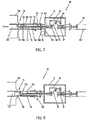
- System 30 may be coupled to a synthesis chamber 31.
- the synthesis chamber 31 in general, includes an entrance end 311, into which reaction gases (i.e., gaseous carbon source) may be supplied, a hot zone 312, where synthesis of extended length nanotubes 313 may occur, and an exit end 314 from which the products of the reaction, namely the nanotubes and exhaust gases, may exit and be collected.
- the synthesis chamber 31, in an embodiment, may include a quartz tube 315 extending through a furnace 316.
- the nanotubes generated by system 30, may be individual nanotubes, bundles of such nanotubes, and/or intertwined nanotubes.
- system 30 may be used in the formation of a substantially continuous non-woven sheet generated from compacted and intermingled nanotubes and having sufficient structural integrity to be handled as a sheet.
- System 30 may also include a housing 32 designed to be substantially airtight, so as to minimize the release of airborne particulates from within the synthesis chamber 31 into the environment.
- the housing 32 may also act to prevent oxygen from entering into the system 30 and reaching the synthesis chamber 31.
- the presence of oxygen within the synthesis chamber 31 can affect the integrity and compromise the production of the nanotubes 313.
- System 30 may also include an injector similar to those disclosed in U.S. Patent 9,061,913 .
- System 30 may also include a moving belt or drum 320 (referred to herein simply as belt 320 for simplicity), positioned within housing 32, designed for collecting synthesized nanotubes 313 made from a CVD process within synthesis chamber 31 of system 30.
- belt 320 may be used to permit nanotubes collected thereon to subsequently form a substantially continuous extensible structure 321, for instance, a non-woven sheet.
- a substantially continuous extensible structure 321 for instance, a non-woven sheet.
- Such a sheet may be generated from a matrix of compacted, substantially non-aligned, and intermingled nanotubes 313, bundles of nanotubes, or intertwined nanotubes, with sufficient structural integrity to be handled as a sheet.
- belt 320 may be positioned adjacent the exit end 314 of the synthesis chamber 31 to permit the nanotubes to be deposited on to belt 320.
- belt 320 may be positioned substantially parallel to the flow of gas from the exit end 314, as illustrated in FIG. 5 .
- belt 320 may be positioned substantially perpendicular to the flow of gas from the exit end 314 and may be porous in nature to allow the flow of gas carrying the nanomaterials to pass therethrough, as shown in FIGS. 6A and 6B .
- belt 320 can be designed to translate from side to side in a direction substantially perpendicular to the flow of gas from the exit end 314, so as to generate a sheet that is substantially wider than the exit end 314.
- Belt 320 may also be designed as a continuous loop, similar to a conventional conveyor belt, such that belt 320 can continuously rotate about an axis, whereby multiple substantially distinct layers of CNT can be deposited on belt 320 to form a sheet 321, such as that shown in FIG. 4 .
- belt 320 in an embodiment, may be looped about opposing rotating elements 322 and may be driven by a mechanical device, such as an electric motor.
- the mechanical device may be controlled through the use of a control system, such as a computer or microprocessor, so that tension and velocity can be optimized.
- the deposition of multiple layers of CNT in formation of sheet 321, in one embodiment can result in minimizing interlayer contacts between nanotubes. Specifically, nanotubes in each distinct layer of sheet 321 tend not to extend into an adjacent layer of sheet 321. As a result, normal-to-plane thermal conductivity can be minimized through sheet 321.
- a pressure applicator such as roller 45
- the pressure application may be situated adjacent to belt 44, that may be positioned substantially perpendicular to the flow of gas, so as to apply a compacting force (i.e., pressure) onto the collected nanomaterials.
- a compacting force i.e., pressure
- the nanomaterials on belt 44 may be forced to move under and against roller 45, such that a pressure may be applied to the intermingled nanomaterials while the nanomaterials get compacted between belt 44 and roller 45 into a coherent substantially-bonded sheet 46.
- a plate 444 may be positioned behind belt 44 to provide a hard surface against which pressure from roller 45 can be applied. It should be noted that the use of roller 45 may not be necessary should the collected nanomaterials be ample in amount and sufficiently intermingled, such that an adequate number of contact sites exists to provide the necessary bonding strength to generate the sheet 46.
- a scalpel or blade 47 may be provided downstream of the roller 45 with its edge against surface 445 of belt 44. In this manner, as sheet 46 moves downstream past roller 45, blade 47 may act to lift the sheet 46 from surface 445 of belt 44. In an alternate embodiment, a blade does not have to be in use to remove the sheet 46. Rather, removal of the sheet 46 may be manually by hand or by other known methods in the art.
- a spool or roller 48 may be provided downstream of blade 47, so that the disengaged sheet 46 may subsequently be directed thereonto and wound about roller 48 for harvesting. As the sheet 46 is wound about roller 48, a plurality of layers may be formed. Of course, other mechanisms may be used, so long as the sheet 46 can be collected for removal from the housing 42 thereafter.
- Roller 48 like belt 44, may be driven, in an embodiment, by a mechanical drive, such as an electric motor 481, so that its axis of rotation may be substantially transverse to the direction of movement of the sheet 46.
- a separation material 49 may be applied onto one side of the sheet 46 prior to the sheet 46 being wound about roller 48.
- the separation material 49 for use in connection with the present invention may be one of various commercially available metal sheets or polymers that can be supplied in a continuous roll 491. To that end, the separation material 49 may be pulled along with the sheet 46 onto roller 48 as sheet 46 is being wound about roller 48. It should be noted that the polymer comprising the separation material 49 may be provided in a sheet, liquid, or any other form, so long as it can be applied to one side of sheet 46.
- the separation material 49 may be a non-magnetic material, e.g., conducting or otherwise, so as to prevent the sheet 46 from sticking strongly to the separation material 49. In an alternate embodiment, a separation material may not be necessary.
- the sheet 46 After the sheet 46 is generated, it may be left as a sheet 46 or it may be cut into smaller segments, such as strips.
- a laser may be used to cut the sheet 46 into strips.
- the laser beam may, in an embodiment, be situated adjacent the housing such that the laser may be directed at the sheet 46 as it exits the housing.
- a computer or program may be employed to control the operation of the laser beam and also the cutting of the strip.
- any mechanical means or other means known in the art may be used to cut the sheet 46 into strips.
- an electrostatic field may be employed to align the nanotubes, generated from synthesis chamber 31, approximately in a direction of belt motion.
- the electrostatic field may be generated, in one embodiment, by placing, for instance, two or more electrodes circumferentially about the exit end 314 of synthesis chamber 31 and applying a high voltage to the electrodes.
- the voltage in an embodiment, can vary from about 10 V to about 100 kV, and preferably from about 4 kV to about 6 kV.
- the electrodes may be shielded with an insulator, such as a small quartz or other suitable insulator. The presence of the electric field can cause the nanotubes moving therethrough to substantially align with the field, so as to impart an alignment of the nanotubes on moving belt.
- the carbon nanotubes can be aligned by stretching following the synthesis of the carbon nanotube sheets as provided in U.S. Application 2012 276 799 A1 .
- System 30 can provide according to the invention bulk nanomaterials of high strength in a non-woven sheet, as shown in FIG. 4 .
- the carbon nanotubes 14, in an embodiment, can be deposited in multiple distinct layers 51 to from a multilayered structure or morphology in a single CNT sheet 210, as shown in FIG. 4 .
- nanofibrous non-woven sheet 210 may be made from the deposition of multiple distinct layers of either SWNT or MWNT carbon nanotubes.
- the tensile strength of such a non-woven sheet 210 can be over 40 MPa for SWNT.
- such a sheet may used with residual catalyst from the formation of the nanotubes. However, typical residuals may be less than 2 atomic percent.
- the bulk nanomaterials can be easily handled while maintaining structural integrity and subsequently processed for end use applications.
- These materials are thermally conductive in-plane, have low thermal mass, are highly flexible, and are resistant to chemical degradation.
- the non-woven sheet 210 of the present invention can provide thermal protection by being thermally conductive within the plane of the sheet 210, while not being thermally conductive in a direction substantially normal to this plane.
- the carbon nanotubes in non-woven sheet 210 may act to conduct heat substantially rapidly away from the heat source, along the plane of the sheet 210, and toward a larger and relatively cooler area, for instance a heat sink.
- the non-woven sheet 210 made from carbon nanotubes generally can withstand (i.e., does not burn) temperature up to about 500°C.
- Non-woven CNT sheet 210 is formed almost entirely of nanotubes.
- Nanotube areal densities in various embodiments of non-woven sheet 210 may range from about 1 g/m 2 to about 50 g/m 2 , and preferably about 10 g/m 2 to about 20 g/m 2 .
- CNT yarn 200 may include, in addition to the nanotubes, carbonaceous materials such as soot and polyaromatic hydrocarbons. These carbonaceous materials, in some embodiments, may be attributable to about 10% of the weight of CNT sheet 210.
- non-woven CNT sheet 210 may vary across embodiments, depending on the desired application; however any particular concentration used may be a function of certain key considerations.
- thermal conductivity in many embodiments, non-woven CNT sheet 210 may be provided with a high enough nanotube concentration to provide a level of thermal conductivity suitable for wicking away heat from a heat source at a desired rate.
- Another such consideration is providing sufficient structural scaffolding for supporting intumescent material 300, and in particular, the foam formed therefrom, as intumescent material 300 undergoes a reaction in the presence of heat, as described in more detail below.
- housing 32 can be replaced with an apparatus to receive nanotubes from the furnace 316 and spin them into yarns.
- the apparatus may include a rotating spindle that may collect nanotubes as they exit tube 315.
- the rotating spindle may include an intake end into which a plurality of tubes may enter and be spun into a yarn.
- the direction of spin may be substantially transverse to the direction of movement of the nanotubes through tube 315.
- Rotating spindle may also include a pathway along which the yarn may be guided toward an outlet end of the spindle. The yarn may then be collected on a spool.
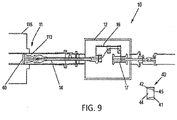
- System 10 may be similar to that disclosed in U.S. Patent 7,993,620 .
- Rotating spindle 14 may be designed to extend from within housing 12, through inlet 13, and into synthesis chamber 11 for collection of extended length nanotubes 113.
- rotating spindle 14 may include an intake end 141 into which a plurality of nanotubes may enter and be spun into a yarn 220.
- the direction of spin may be substantially transverse to the direction of movement of the nanotubes 113.
- Rotating spindle 14 may also include a pathway, such as hollow core 142, along which yarn 220 may be guided toward outlet end 143 of spindle 14.
- the intake end 141 of rotating spindle 14 may include a variety of designs.
- intake end 141 may simply include an aperture (not shown) through which the nanotubes 113 may enter.
- it may include a funnel-like structure 144 that may serve to guide the nanotubes 113 into the intake end 141.
- Structure 144 can also serve to support yarn 220, should it break, until such time that it might be able to reconstitute itself from the twisting with newly deposited nanotubes 113.
- a roller, capstan or other restrictive devices+ may be provided adjacent the intake end 141 of spindle 14 in order to: (1) serve as a point from which yarn 220 may be twisted, and (2) prevent springiness in yarn 220 from pulling the yarn too quickly into the core 142 of spindle 14, which can prevent yarn 220 from re-forming if it were to break.
- System 10 further includes a guide arm 16 which may be coupled to the outlet end 143 of rotating spindle 14 to guide and direct yarn 220 toward a spool 17 for gathering thereon.
- a set of pulleys 161, eyelets, or hooks may be provided as attachments to the guide arm 16 to define a path on which yarn 220 may be directed along the guide arm 16.
- yarn 220 may be permitted to pass through a tubular structure (not shown) that can direct yarn 220 from the outlet end 143 of spindle 14 to a point from which yarn 220 may be wound onto spool 17.
- Guide arm 16 and rotating spindle 14, in an embodiment, may work together to induce twisting in yarn 220.
- the rotation of spindle 14 and guide arm 16 may be mechanically driven, for example, by an electric motor 18 coupled to the spindle 14 via a belt 181, for instance.
- Spool 17, situated within housing 12, may be positioned, in one embodiment, downstream of guide arm 16 for the harvesting of yarn 220.
- yarn 220 advancing from guide arm 16 may be directed on to a spinning spool 17, such that yarn 220 may thereafter be wound circumferentially about spool 17.
- spool 17 may be placed at any other location within housing 12, so long as spool 17 may be spun about its axis to collect yarn 220 from guide arm 16.
- the axis of spin of spool 17 may be substantially transverse to the direction of movement of yarn 220 onto spool 17.
- an additional mechanical drive 19 may be coupled to spool 17.
- spool 17 may be synchronized to spin or rotate near or at substantially a similar rotation rate as that of spindle 14 to permit uniform harvesting of yarn 220 on to spool 17. Otherwise, if, for instance, the rate of rotation of spool 17 is faster than that of spindle 14, breakage of yarn 220 from guide arm 16 to spool 17 may occur, or if the rate is slower than that of spindle 14, loose portions from yarn 220 may end up entangled.
- control system may be designed to receive data from position sensors, such as optical encoders 182, attached to each of mechanical drives 17 and 18. Subsequently, based on the data, the control system may use a control algorithm in order to modify power supplied to each drive in order to control the rate of each drive so that they substantially match the rate of nanotube synthesis.
- the control system can impart: (1) constant yarn velocity controlled by set tension limits, or (2) constant tension controlled by velocity limits.
- the yarn velocity can be reset in real time depending on the tension values, so that the tension may be kept within a preset limit.
- the yarn tension can be reset in real time depending on the velocity values, so that the tension can be kept within a set value.
- the control system can also vary the rate between the spool 17 and spindle 14, if necessary, to control the yarn up-take by the spool 17.
- the control system can cause the spool 17 to move back and forth along its axis, so as to permit the yarn 220 to be uniformly wound thereabout.
- extended length nanotubes may be collected from within the synthesis chamber 11 and yarn 220 may thereafter be formed.
- the nanotubes 113 may be collected into a bundle, fed into the intake end 141 of spindle 14, and subsequently spun or twist into yarn 220 therewithin.
- a continual twist to yarn 220 can build up sufficient angular stress to cause rotation near a point where new nanotubes 113 arrive at the spindle 14 to further the yarn formation process.
- a continual tension may be applied to yarn 220 or its advancement may be permitted at a controlled rate, so as to allow its uptake circumferentially about spool 17.
- the formation of yarn 220 results from a bundling of nanotubes 113 that may subsequently be tightly spun into a twisting yarn.
- a main twist of yarn 220 may be anchored at some point within system 10 and the collected nanotubes 113 may be wound on to the twisting yarn 220.
- a vortex generator such as gas-spinner 20, may be provided toward the exit end 114 of synthesis chamber 11 to generate a substantial vortex flow in order to impart a twisting motion to the nanotubes 113 prior to being directed into spindle 14 and spun into yarn 220.
- the generation of a vortex to impart twisting motion may also serve to even out an amount of nanotube material used in the formation of yarn 220.
- gas-spinner 20 can also allow substantial freedom in defining yarn and tow formation modes for system 10. Moreover, to the extent necessary, gas-spinner 20 can provide an area where nanotubes 113 may accumulate, particularly when the gas supplied through the gas-spinner 20 is at a low flow rate to create a source from which nanotubes 113 may be pulled, such as that by a leader (see description below) to subsequently twist into yarn 220.
- leader may be an additional piece of nanotube yarn, some other type of yarn or filament, or a thin wire.
- a wire may be used because it can provide the requisite stiffness necessary to transfer the twisting motion of the spindle 14 to the accumulating webbing or bundle of nanotubes 113 until there exist a sufficient build-up, such that the wire can tether an end of a growing yarn.
- the wire used in one embodiment, may be, for example, a ferrous wire or Nichrome, since these alloys can withstand the temperature within the hot zone (600°C - 1300°C) of the synthesis chamber 11.
- nanotubes produced via a CVD process have been observed to adhere relatively well to these alloys.
- catalytic nanoparticles at the end of the nanotubes 113 may include ferromagnetic materials, such as Fe, Co, Ni, etc., these nanoparticles can magnetically attract to the magnetic domains on the ferrous alloy materials.
- a leader it may be necessary to pre-thread the leader before the start of the reaction.
- a hole in one embodiment, may be provided in the spool 17 to serve as an anchor point for one end of the leader.
- notches or slots may be provided in the guide pulleys 161 to permit the leader to be easily inserted into the guide arm 16. The leader may then be inserted into the spindle 14, and thereafter advanced into the synthesis chamber 11 upstream to gas-spinner 20, should one be employed.
- an anchor 40 may be provided in place of gas-spinner 20 to provide a source from which the leader can pull nanotubes into the spindle 14 to initiate the yarn making process.
- anchor 40 may be positioned toward the exit end 114 of synthesis chamber 11 to constrict the flow of gas and nanotubes 113 so that an accumulation of nanotubes 113 can be generated within the anchor 40.
- anchor 40 may be designed as a disc having a distal end 41, a proximal end 42, and a passageway 44 extending therebetween. As illustrated in Fig. 6 , passageway 44 may taper from the proximal end 42 toward the distal end 41.
- passageway 44 of anchor 40 may be designed to include a variety of forms, so long as it works to constrict the flow of gas and nanotubes 113 in chamber 11.
- anchor 40 can be positioned near furnace 116 where the nanotubes 113 may have a relatively greater tendency to adhere to solid surfaces. As it may be near furnace 16, anchor 40 may be made, in an embodiment, from a graphite material or any other material that would withstanding heat from furnace 16.
- anchor 40 can act to provide a point from which the nanotubes 113 can be pulled to permit substantial alignment of the nanotubes 113 in a direction substantially coaxial with yarn 220.
- the ability to align the nanotubes 113 along an axis of yarn 220 can enhance load transfer between the nanotubes 113 to allow for the formation of a high strength yarn 220. Nevertheless, it should be appreciated that yarn 220 can be formed regardless of whether anchor 40 is present.
- Synthesis and harvesting of yarn 220 may subsequently be initiated by causing the spool 17, spindle 14, guide arm 16, and leader to rotate.
- the nanotubes 113 may be directed toward the leader to permit build-up or bundling of the nanotubes 113 thereon. Thereafter, once a webbing or bundling of nanotubes 113 begins to build up on the leader, and the leader can be withdrawn by causing the spool 17 to rotate at a slightly different rate than the spindle 14 and guide arm 16.
- the formation of the nanotube yarn 220 as described above, may proceed automatically thereafter once the leader has been withdrawn sufficiently from the hot zone 112 of synthesis chamber 11.
- the webbing of nanotubes 113 may be twisted into a yarn 220 at a point near the intake end 141 of spindle 14.
- the twisted portions of yarn 220 may then be allowed to move along the core 142 towards the outlet end 143 of spindle 14.
- the yarn 220 may be guided along guide arm 16 and directed toward the spool 17.
- the yarn 220 may thereafter be wound about spool 17 at a controlled rate.
- the system 10 may also be used for continuous formation of a tow (not shown) from nanotubes 113 synthesized within synthesis chamber 11.
- This tow may be later processed into a tightly wound yarn, similar to technologies common in the art of thread and yarn formation.
- the tow may be collected using the hollow spindle 14, guide arm 16 and spool 17, as described above.
- the formed tow may extend from the spool 17, through the guide arm 16 and spindle 14 into the synthesis chamber 11 near the exit end 114.
- Nanotubes 113 in an embodiment, may accumulate on the tow by winding around the tow, as the tow spins rapidly and is slowly withdrawn.
- An anchor may not required for this mode of operation. However, should it be necessary to provide a point to which the growing end of the spinning tow may attach, an anchor may be used.
- the formation of a yarn or tow in accordance with one embodiment provides an approach to producing a relatively long fibrous structure capable of being employed in applications requiring length.
- the twisting action during formation of the yarn allows the staple fibers (i.e., nanotubes) to be held together into the larger fibrous structure (i.e., yarn).
- the twisting of axially aligned fibers i.e., nanotubes
- staple fibers according to the invention can be provided with a high aspect ratio (e.g., > 100:1 length:diameter). As a result, they can serve better than those with smaller aspect ratios to transfer structural loads between individual fibers within a yarn. While fibers with essentially infinite aspect ratio would be ideal, the length scale of structures in which the yarn may be incorporated better defines the length and aspect ratios required of the constituent fibers. For example, if it is necessary to bridge a distance of only one to two centimeters, fibers much longer than this distance may not required. Furthermore, within a yarn, load transfer typically occurs as an interaction between each of the contact points of adjacent fibers.
- a high aspect ratio e.g., > 100:1 length:diameter
- each fiber may interact via, for example, a van der Waal's bond, hydrogen bond, or ionic interaction.
- the presence of a plurality of fibers in the yarn of the present invention can increase the number of contact points and thus the bonding interaction between adjacent fibers to enhance load transfer between the fibers.
- twisting can further increase the number of contact points between constituent fibers in a yarn by forcing individual fibers closer together, it can be advantageous to the overall strength of the yarn to impart twisting.
- the ability to independently control twisting and up-take velocity can be important in order to optimize strength.
- the strength of the yarn can further be enhanced by increasing the bond strength between adjacent fibers.
- the yarn may be impregnated with a matrix material, such as a polymer, or a surfactant molecule to crosslink adjacent fibers. Crosslinking the fibers using covalent or ionic chemical bonds can provide an additional means of improving the overall strength of the yarn.
- the imparting of a twist to the yarn can also enhance the electrical and thermal conductivity of the yarn of the present invention.
- the carbon nanotubes in yarn 220 may act to conduct heat substantially rapidly away from the heat source, along the length of the yarn 220, and toward a larger and relatively cooler area, for instance a heat sink.
- CNT yarn 220 in many embodiments, is formed almost entirely of nanotubes. Nanotube linear densities in various embodiments of CNT yarn 220 may range from about 0.5 Tex (g/km) to about 100 Tex or higher. In some embodiments, there may be contaminants, such as iron (residual catalyst) attributable to between about 10% to about 15% of the weight of CNT yarn 220. Additionally or alternatively, CNT yarn 220 may include, in addition to the nanotubes, carbonaceous materials such as soot and polyaromatic hydrocarbons. These carbonaceous materials, in some embodiments, may be attributable to about 10% of the weight of CNT yarn 220.
- the concentration of carbon nanotubes in CNT yarn 220 may vary across embodiments, depending on the desired application; however any particular concentration used may be a function of certain key considerations.
- One such consideration is thermal conductivity - in many embodiments, CNT yarn 220 may be provided with a high enough nanotube concentration to provide a level of thermal conductivity suitable for wicking away heat from a heat source at a desired rate.
- Another such consideration is providing sufficient structural scaffolding for supporting intumescent material 300, and in particular, the foam formed therefrom, as intumescent material 300 undergoes a reaction in the presence of heat, as described in more detail below.
- CNT member 200 may include a woven CNT sheet 230 formed by weaving together, braiding, knitting, or otherwise combining in like manner multiple carbon nanotube yarns 220.
- woven CNT sheet 230 may exhibit good in-plane thermal conductivity, thereby helping to dissipate heat away from hot spots in an in-plane direction whilst minimizing through-plane heat transfer.
- thermal energy may follow the independent conduction pathways form by each CNT yarns 220 woven into woven CNT sheet 230, carrying heat away from a hot spot in the X- and Y- directions with which the CNT yarns 220 are aligned.
- Woven CNT sheet 230 owing to the high strength of CNT yarns 220 from which it is made, may exhibit very high tensile strengths relative to non-woven sheets.
- CNT member 200 may be a composite article comprising woven CNT sheet 230 placed in contact with a non-woven CNT sheet 210. Such a configuration may exhibit the favorable characteristics of sheets 210 and 230.
- woven CNT sheet 230 may contribute superior strength and thermal conductivity to the composite article, and non-woven CNT sheet 210 may contribute greater surface area and different microstructure.
- Intumescent material 300 in various embodiments, could be introduced into the yarns of woven CNT sheet 230, into the interstices between the yarns woven CNT sheet 230, into non-woven CNT sheet 210, or any combination thereof.
- CNT member 200 may take the form of a CNT network 240.
- CNT network 240 is formed by drying a solution of dispersed carbon nanotubes in a solvent.
- CNT network 240 may further include one or more additives such as, without limitation, surfactants (for enhancing uniformity with which the nanotubes are distributed throughout the solution used to form the network), acids (for same purpose, as well as functionalizing the nanotubes), binder (for increasing viscosity of the solution and holding the various components of the network together).
- intumescent material 300 may be mixed into the solution used to form CNT network 240 to provide enhanced thermal protection capabilities.
- the resulting solution of nanostructured materials, intumescent material 300, and solvent may be coated or sprayed onto a surface and dried to form a thermally-protective coating (an embodiment of intumescent nanostructured material 100) including CNT network 240 and intumescent material 300, as later described in more detail.
- the solution of nanostructured materials may be prepared according to any suitable method known in the art. Representative methods for forming the solution may be found in U.S. patent application US 2016 153 519 12 A .
- the concentration of nanostructured materials in the solution may vary across embodiments, depending on the desired application; however any particular concentration used may be a function of certain key considerations.
- One such consideration is thermal conductivity - in many embodiments, the solution may be provided with a high enough nanotube concentration to provide a level of thermal conductivity suitable for wicking away heat from a heat source at a desired rate.
- Another such consideration is providing sufficient structural scaffolding for supporting intumescent material 300 in CNT network 240, and in particular, the foam formed therefrom, as intumescent material 300 undergoes a reaction in the presence of heat, as described in more detail below.
- the solution in furtherance of these considerations, may contain carbon nanotubes in concentrations ranging from about 1% to about 80%, and preferably around 10% by volume.
- Embodiments of intumescent nanostructured material 100 of the present invention further include one or more intumescent materials 300 for enhancing thermal protection.
- intumescent materials When exposed to heat, intumescent materials undergo chemical reactions that results in the formation of a foam that insulates material 100 from further heat exposure and oxygen. During the reaction, heat energy is absorbed as hydrates boil and water vapor is released, thereby providing a cooling effect as the energy of vaporization is consumed.
- many intumescent materials may undergo reaction and form the foam when exposed to temperatures of about 400°C or greater.
- Intumescent material 300 may include any suitable material that undergoes such an endothermic chemical reaction resulting in the formation of an insulating foam or similar material.
- Example intumescent materials include, without limitation, soft char (e.g., ammonium polyphosphate, pentaeyrthritol, and melamine in a binder of vinyl acetate or styrene acrylates) and hard char (e.g., sodium silicates, graphite).
- Intumescent material 300 may further include or be combined with a binder (e.g., various polymeric resins) for bonding material 300 to other materials, a blowing agent (e.g., melamine or urea) that thermally decomposes to produce gasses to facilitate formation of the intumescent foam, and/or fire-proofing agents (e.g., boric acid, borax, zinc borate, silazanes, ammonium polyphosphate) for preventing oxidation of materials in contact with intumescent material 300 (e.g., CNTs).
- a binder e.g., various polymeric resins
- a blowing agent e.g., melamine or urea
- fire-proofing agents e.g., boric acid, borax, zinc borate, silazanes, ammonium polyphosphate
- any suitable intumescent material with the properties described herein is envisioned within the scope of the present disclosure.
- Intumescent material 300 may be applied to CNT member 200 in any suitable manner.
- intumescent material 300 may be dissolved in an appropriate solvent, rinsed into CNT member 200, which may then be dried to remove the solvent. Additional details are provided in Examples 1-8 below.
- Synergies between CNT member 200 and intumescent 300 may allow for the creation of thicker foams with closed-cell morphologies as compared with those foams formed from intumescents included in polymer matrices.
- the high densities of carbon nanotubes included in CNT member 200 provide ample scaffolding for supporting the foam as it forms such that the cells of the foam are less likely to pop and collapse.
- the foam can grow thicker and retain a highly-insulting closed-cell morphology.
- the synergies between CNT member 200 and intumescent 300 can be expected to lead to the generation of foams having smaller, stronger cells as compared to unsupported intumescents or intumescents mixed with non-CNT materials. Without wishing to be bound by theory, it is thought that the strength imparted by CNT member 200 reinforces the closed cells of the foam, causing smaller, more stable cells to form.
- Embodiments of intumescent material 100 according to the invention can additionally be coated or impregnated with a ceramifying polymer material 400 to enhance the strength of the CNT member 200 and its oxidation resistance characteristics.
- Example ceramifying polymer materials include, without limitation, polysilazane, polyureasilazane (PSZ), and Polyureamethylvinylsilazane Ceraset® (Kion Corporation, Huntingdon Valley, PA).
- PSZ 400 polyureasilazane
- Ceraset® Polyureamethylvinylsilazane Ceraset®
- ceramifying polymer material 400 may be referred to herein as PSZ 400; however, it should be understood that the present disclosure is not intended to limit ceramifying polymer material 400 to only this embodiment.
- PSZ resin 400 may react with heat to form a heat-resistant ceramic coating on the carbon nanotubes of CNT member 200. This ceramic coating may help prevent or otherwise reduce thermal degradation or burning of the carbon nanotubes when exposed to high levels of
- PSZ 400 may be coated onto or impregnated into non-woven sheet 210, yarn 220, and woven sheet 230.
- the PSZ 400 400 may be dissolved in acetone solutions in concentrations ranging from about 0.1% to about 20%, preferable around 3% by weight.
- the solution may be coated onto the CNT member 200, and then allowed to air dry.
- the coated CNT member 200 may be hot pressed at an elevated temperature ranging from about 50°C to about 300°C, and preferably around 200°C, for about 120 minutes.
- the pressure at which the hot pressing may be carried out can range from about 101,35 kPa (14.7 psi) to about 137895 kPa (20,000 psi).
- PSZ 400 may be attributable to about 5% to about 80% of the weight of the PSZ 400-coated CNT member 200 (before application of intumescent material 300), and preferably about 20% to about 30% of the weight of the PSZ 400-coated CNT member 200 (before application of intumescent material 300).
- the strength of this coated CNT member 200 can be increased as a result of this process from about 30 MPa to over about 300 MPa.
- exposure of the PSZ 400 coated CNT member 200 to a MAAP flame does not results in burning of the material. Rather, the silazane is converted to silicon oxide and most probably forms regions of well-bonded silicon carboid locking the structure together.
- a CNT member 200 coated with PSZ 400 can withstand heat over 1000°C or higher without burning for several minutes.
- PSZ 400 can also be included in varying concentrations in the solution used to form CNT network 240.
- PSZ 400 may be added in suitable concentrations to the solution such that PSZ 400 accounts for about 2% to about 50%, and preferably about 25%, of the dry weight of CNT network 240.
- the PSZ 400 may exhibit certain synergies with intumescent material 300, beyond simply forming a protective ceramic coating around the nanotubes.
- PSZ 400 may undergo an endothermic reaction as it thermally decomposes, thus providing further thermal protection for intumescent nanostructured material 100 and the persons, animals, or objects it protects.
- Intumescent nanostructured materials 100 of the present invention may be further treated to improve its mechanical integrity and/or thermal performance.
- material 100 may be coated and/or infiltrated with a polymer(s), which may protect the material from water, humidity and weather, as well as possibly affect the formation of the foam as intumescent material 300 undergoes endothermic reaction.
- a polymer(s) which may protect the material from water, humidity and weather, as well as possibly affect the formation of the foam as intumescent material 300 undergoes endothermic reaction.
- Example polymers suitable for these purposes include, without limitation, PVC, EPDM, and Aramids. In an embodiment, these polymers may be added via dissolved monomers, or oligomers added together and reacted once infiltration is complete.
- intumescent nanostructured material 100 may be coated and/or infiltrated with a flame retardant chemical(s), such as boric acid, borax, zinc borate, ammonium polyphosphate (APP), or any combination thereof. Testing has shown particularly favorable synergies between boric acid and APP, for example.
- a flame retardant chemical(s) such as boric acid, borax, zinc borate, ammonium polyphosphate (APP), or any combination thereof. Testing has shown particularly favorable synergies between boric acid and APP, for example.
- Embodiments of an intumescent nanostructured material 110 may include non-woven CNT sheet 210, intumescent material 300, and ceramifying polymer 400.
- non-woven CNT sheet 210 may account for about 10% to about 50% of the dry weight of intumescent nanostructured material 110
- intumescent material 300 may account for about 0% to about 70% of the dry weight of intumescent nanostructured material 110
- ceramifying polymer material 400 may account for about 25% of the dry weight of intumescent nanostructured material 110.
- intumescent nanostructured material 110 may further include binder (e.g., vinyl acetate, styrene acrylates or polyurethane), which may account for about 3% to about 50% of the dry weight of intumescent nanostructured material 110. Additionally or alternatively, some embodiments of intumescent nanostructured material 110 may include flame retardant material(s) (e.g., boric acid), which may account for about 5% of the dry weight of intumescent nanostructured material 110.
- binder e.g., vinyl acetate, styrene acrylates or polyurethane
- flame retardant material(s) e.g., boric acid
- the intumescent nanostructured material 110 of Example 1 may be coated with intumescent material 140 (later described in Example 8) to form intumescent material 112.
- a composite 114 may be formed by building up multiple layers of intumescent material 112 for enhanced thermal protection.
- Embodiments of an intumescent nanostructured material 120 may include CNT yarn 220, intumescent material 300, and ceramifying polymer 400.
- CNT yarn 220 may account for about 10% to about 90% of the dry weight of intumescent nanostructured material 120
- intumescent material 300 may account for about 0% to about 50% of the dry weight of intumescent nanostructured material 120
- ceramifying polymer material 400 may account for about 30% of the dry weight of intumescent nanostructured material 120.
- intumescent nanostructured material 120 may further include binder (e.g., vinyl acetate or styrene acrylates), which may account for about 0% to about 50% of the dry weight of intumescent nanostructured material 120. Additionally or alternatively, some embodiments of intumescent nanostructured material 120 may include flame retardant material(s) (e.g., boric acid), which may account for about 5% of the dry weight of intumescent nanostructured material 120.
- binder e.g., vinyl acetate or styrene acrylates
- flame retardant material(s) e.g., boric acid
- the intumescent nanostructured material 120 of Example 3 may be coated with intumescent material 140 (later described in Example 8) to form intumescent material 122.
- a composite 124 may be formed by building up multiple layers of intumescent material 122 (e.g., twisting multiple yarns to form a wire or rope) for enhanced thermal protection.
- Embodiments of an intumescent nanostructured material 130 may include woven CNT sheet 230, intumescent material 300, and ceramifying polymer 400.
- non-woven CNT sheet 230 may account for about 0% to about 50% of the dry weight of intumescent nanostructured material 130
- intumescent material 300 may account for about 10% to about 80% of the dry weight of intumescent nanostructured material 130
- ceramifying polymer material 400 may account for about 30% of the dry weight of intumescent nanostructured material 130.
- intumescent nanostructured material 130 may further include flame retardant material(s) (e.g., boric acid), which may account for about 5% of the dry weight of intumescent nanostructured material 130.
- flame retardant material(s) e.g., boric acid
- the intumescent nanostructured material 130 of Example 5 may be coated with intumescent material 140 (later described in Example 8) to form intumescent material 132.
- a composite 134 may be formed by building up multiple layers of intumescent material 132 for enhanced thermal protection.
- the intumescent nanostructured material 132 or composite 134 of Example 6 may be overlaid with a non-woven CNT sheet 210 or intumescent material 110 to form intumescent material 136.
- a composite 138 may be formed by building up multiple layers of intumescent material 136 for enhanced thermal protection.
- Embodiments of a thermally-protective coating 140 may include CNT network 240, intumescent material 300, and ceramifying polymer 400.
- CNT network 240 may account for about 1% to about 10% of the dry weight of intumescent nanostructured material 140
- intumescent material 300 may account for about 0% to about 70% of the dry weight of intumescent nanostructured material 140
- ceramifying polymer material 400 may account for about 25% of the dry weight of intumescent nanostructured material 140.
- intumescent nanostructured material 140 may further include binder (e.g., vinyl acetate or styrene acrylates), which may account for about 3% to about 10% of the dry weight of intumescent nanostructured material 140. Additionally or alternatively, some embodiments of intumescent nanostructured material 140 may include flame retardant material(s) (e.g., boric acid), which may account for about 5% of the dry weight of intumescent nanostructured material 140. Solvent (e.g., acetone, xylenes, 1-methyl pyrholidone) may be used to adjust the viscosity of intumescent nanostructured material 140 to be suitable for layering or spraying.
- binder e.g., vinyl acetate or styrene acrylates
- flame retardant material(s) e.g., boric acid
- Solvent e.g., acetone, xylenes, 1-methyl pyrholidone
- solvent e.g.
- solvent may be utilized to adjust the viscosity of intumescent nanostructured material 140 to about 3 Pa ⁇ s (3000) centipoise to about 6 Pa ⁇ s (6000) centipoise for coating/layering, and to about less than 1 Pa ⁇ s (1000) centipoise for spraying.
- intumescent nanostructured material 140 may be formed by rinsing a nanotube pulp in an about 2% to about 20% solution of ceramifying polymer 400 (e.g., Ceraset monomer) in acetone.
- ceramifying polymer 400 e.g., Ceraset monomer
- the rinsed nanotube pulp may then be dried in an oven, for example, at about 100°C for about 30 minutes to dry the ceramifying polymer 400 on the nanotubes.
- the coated nanotube pulp may be further baked to solidify the ceramifying polymer 400, for example, at about 200°C for about 1 hour.
- the nanotubes now include a ceramifying polymer coating for additional protection.
- the nanotube pulp may be combined with intumescent material 300 (e.g., soft char, hard char), and any combination of binder, flame retardant, and solvent to create a viscous solution.
- intumescent material 300 e.g., soft char, hard char
- the solution may be mixed in a high shear mixer until the nanotube pulp and intumescent material 300 are fully dispersed.
- the solution may then be diluted until it is the proper viscosity for coating/layering, spraying, or other suitable application.
- the solution may be mixed into liquid paint for coating or spraying onto an object for thermal protection.
- liquid paint for coating or spraying onto an object for thermal protection.
- about 2.5 g of coated nanotube pulp may be mixed well with about 100 g acrylic paint, along with about 5 g of boric acid, about 5 g of ammonium polyophosphate, and about 2.5 g of melamine. This may be diluted with 5% ethanol in water until a viscosity suitable for spraying is obtained. The viscous mixture is then ready for spraying on an object to provide thermal protection.
- suitable paints may include, without limitation, polyurethane- and oilbased paints.
- Intumescent nanostructured material 100 may be used in a variety of practical applications, and in particular, for thermal protection and fire protection.
- embodiments of material 100 formed from non-woven sheets 210 or woven sheets 230 may be integrated into or used as textiles, such as, without limitation, in fire blankets, firefighter suits, and fire-protective clothing for race car drivers, pilots, and the like.
- embodiments of material 100 including yarns 220 may be used in such textiles, as well as in other applications such as in cables and wires that may operate in hot environments or in close proximity to heat sources.
- Each may also be used in structures like fire-resistant or heat tolerant housings around heat sources like engines and heaters, or to surround things needing protection in an otherwise hot environment.
- camping tents, awnings, and other structures often situated near flames or hot lamps may similarly benefit from incorporation of material 100.
- the solution may be used to form thermally-protective layers 140 on components requiring thermal or fire protection.
- the solution may be spray coated onto surfaces of I-beams and other structural members in buildings and vehicles and dried to form intumescent nanostructured material 140 thereon, which may prevent or delay weakening and ultimate collapse of the structure in the event of a fire.
- the solution may be sprayed onto a substrate, dried, and peeled off as a sheet for similar applications as those listed above. The same may be done with the solution by filtering or molding the solution or CNT pulp to form a buckypaper-like form of intumescent nanostructured material 100.
- Such embodiments may be used in ways similar to sheets 210, 230 as described above. Additionally or alternatively, the solution could be coated onto and/or infiltrated into non-woven CNT sheet 210, CNT yarn 220, woven CNT sheet 230, or any combination thereof.
- intumescent nanostructured material 100 may be applied to the back of a CNT heating element to provide a low-mass, fireproof insulating layer to keep the thermal energy of the heating elements from being conducted away from the target to be heated.
- an integrated CNT heater and insulator backing may be formed by backing a CNT sheet or woven CNT yarn with intumescent nanostructured material 140 and appropriate additives. Such an article may be thermally processed at high temperature to create a stable heater with an integrated, flexible, insulated backing.
Landscapes
- Chemical & Material Sciences (AREA)
- Engineering & Computer Science (AREA)
- Materials Engineering (AREA)
- Organic Chemistry (AREA)
- Life Sciences & Earth Sciences (AREA)
- Wood Science & Technology (AREA)
- Inorganic Chemistry (AREA)
- Nanotechnology (AREA)
- Textile Engineering (AREA)
- General Physics & Mathematics (AREA)
- Crystallography & Structural Chemistry (AREA)
- Condensed Matter Physics & Semiconductors (AREA)
- Mechanical Engineering (AREA)
- Physics & Mathematics (AREA)
- Manufacturing & Machinery (AREA)
- Composite Materials (AREA)
- Carbon And Carbon Compounds (AREA)
- Chemical Or Physical Treatment Of Fibers (AREA)
- Compositions Of Macromolecular Compounds (AREA)
- Treatments For Attaching Organic Compounds To Fibrous Goods (AREA)
- Laminated Bodies (AREA)
Claims (11)
- Intumeszentes nanostrukturiertes Material für thermischen Schutz, umfassend:ein Teil, das eine Mehrzahl von Kohlenstoff-Nanoröhrchen einschließt, wobei das Teil ein Vliesstoff, ein Gewebe, ein Garn oder ein Netzwerk ist; undein intumeszentes Material, das mit dem Teil assoziiert und so konfiguriert ist, dass es in Gegenwart einer Wärmequelle reagiert, um einen Schaum zum thermischen Isolieren des Teils von der Wärmequelle zu bilden.
- Intumeszentes nanostrukturiertes Material nach Anspruch 1, wobei das intumeszente Material Weichkohle, Hartkohle oder eine Kombination davon einschließt.
- Intumeszentes nanostrukturiertes Material nach Anspruch 2, wobei die Weichkohle eines oder eine Kombination von Ammoniumpolyphosphat, Pentaerythritol und Melamin in einem Bindemittel aus Vinylacetat oder Styrolacrylaten einschließt.
- Intumeszentes nanostrukturiertes Material nach Anspruch 2, wobei die Hartkohle eines oder eine Kombination von Natriumsilicat oder Graphit einschließt.
- Intumeszentes nanostrukturiertes Material nach Anspruch 1, wobei das intumeszente Material kombiniert ist mit einem Treibmittel, das sich thermisch zersetzt, um Gase zu erzeugen, um die Bildung des Schaums zu erleichtern.
- Intumeszentes nanostrukturiertes Material nach Anspruch 1, wobei das intumeszente Material auf das Teil aufgebracht, in das Teil hinein infiltriert oder mit dem Teil vermischt ist.
- Intumeszentes nanostrukturiertes Material nach Anspruch 1, wobei das intumeszente Material zur Bildung des Schaums bei Temperaturen bei oder oberhalb von etwa 400°C reagiert.
- Intumeszentes nanostrukturiertes Material nach Anspruch 1, das weiter eines oder eine Kombination von einem keramifizierenden Polymermaterial, das die Mehrzahl von Kohlenstoff-Nanoröhrchen überzieht, und einem Flammhemmmittel zum Schützen der Kohlenstoff-Nanoröhrchen vor Oxidation in Gegenwart der Wärmequelle einschließt.
- Lösung, umfassend:eine Mehrzahl von Kohlenstoff-Nanoröhrchen,ein intumeszentes Material undein Lösemittel;wobei die Lösung eine Viskosität aufweist, die geeignet ist zum Beschichten oder Aufsprühen auf eine Oberfläche eines Substrats, und die Konzentration der Kohlenstoff-Nanoröhrchen in der Lösung etwa 1 Vol.-% bis etwa 80 Vol.-% beträgt.
- Intumeszentes nanostrukturiertes Material zum thermischen Schutz, umfassend:ein Teil mit einer ersten Mehrzahl von Kohlenstoff-Nanoröhrchen; undeine Beschichtung auf einer Oberfläche des Teils, wobei die Beschichtung eine zweite Mehrzahl von Kohlenstoff-Nanoröhrchen und ein intumeszentes Material einschließt;wobei das intumeszente Material der Beschichtung so konfiguriert ist, dass es in der Gegenwart einer Wärmequelle reagiert, um einen Schaum zum thermischen Isolieren des Teils vor der Wärmequelle zu bilden, und wobei die Mehrzahl von Kohlenstoff-Nanoröhrchen der Beschichtung so konfiguriert ist, dass sie das intumeszente Material während der Bildung des Schaums unterstützen.
- Intumeszentes Material nach Anspruch 10, wobei das Teil ein Vliesstoff, ein Gewebe, ein Garn oder ein Netzwerk ist.
Applications Claiming Priority (1)
| Application Number | Priority Date | Filing Date | Title |
|---|---|---|---|
| PCT/US2017/012722 WO2018128632A1 (en) | 2017-01-09 | 2017-01-09 | Intumescent nanostructured materials and methods of manufacturing same |
Publications (3)
| Publication Number | Publication Date |
|---|---|
| EP3565859A1 EP3565859A1 (de) | 2019-11-13 |
| EP3565859A4 EP3565859A4 (de) | 2020-08-19 |
| EP3565859B1 true EP3565859B1 (de) | 2021-08-11 |
Family
ID=62791154
Family Applications (1)
| Application Number | Title | Priority Date | Filing Date |
|---|---|---|---|
| EP17890520.4A Active EP3565859B1 (de) | 2017-01-09 | 2017-01-09 | Nanostrukturierte intumeszente materialien und verfahren zur herstellung davon |
Country Status (6)
| Country | Link |
|---|---|
| EP (1) | EP3565859B1 (de) |
| JP (1) | JP6964673B2 (de) |
| KR (1) | KR102662818B1 (de) |
| CN (2) | CN110312765B (de) |
| ES (1) | ES2895674T3 (de) |
| WO (1) | WO2018128632A1 (de) |
Families Citing this family (1)
| Publication number | Priority date | Publication date | Assignee | Title |
|---|---|---|---|---|
| CN109554028B (zh) * | 2018-11-28 | 2020-02-18 | 华南理工大学 | 具有火灾预警和自修复功能的高效阻燃涂料及其制备方法与应用 |
Family Cites Families (26)
| Publication number | Priority date | Publication date | Assignee | Title |
|---|---|---|---|---|
| US5645926A (en) * | 1992-03-20 | 1997-07-08 | British Technology Group Limited | Fire and heat resistant materials |
| US8796162B2 (en) * | 2001-05-14 | 2014-08-05 | Precision Fabrics Group, Inc. | Thermally protective flame retardant fabric |
| US6706793B2 (en) * | 2002-01-23 | 2004-03-16 | Delphi Technologies, Inc. | Intumescent fire retardant composition and method of manufacture thereof |
| US6809129B2 (en) * | 2002-01-23 | 2004-10-26 | Delphi Technologies, Inc. | Elastomeric intumescent material |
| JP4864093B2 (ja) | 2005-07-28 | 2012-01-25 | ナノコンプ テクノロジーズ インコーポレイテッド | ナノ繊維質材料の形成および収穫に関するシステムおよび方法 |
| US8535791B2 (en) * | 2006-06-30 | 2013-09-17 | The University Of Akron | Aligned carbon nanotube-polymer materials, systems and methods |
| JP5595737B2 (ja) * | 2007-02-27 | 2014-09-24 | ナノコンプ テクノロジーズ インコーポレイテッド | 熱保護材料およびその製造方法 |
| US9061913B2 (en) | 2007-06-15 | 2015-06-23 | Nanocomp Technologies, Inc. | Injector apparatus and methods for production of nanostructures |
| WO2009029341A2 (en) | 2007-07-09 | 2009-03-05 | Nanocomp Technologies, Inc. | Chemically-assisted alignment of nanotubes within extensible structures |
| US8632879B2 (en) * | 2008-04-25 | 2014-01-21 | The University Of Kentucky Research Foundation | Lightweight thermal management material for enhancement of through-thickness thermal conductivity |
| US8828487B2 (en) * | 2010-09-03 | 2014-09-09 | Transhield Technology As | Vapor permeable fabric constructs |
| WO2012044382A1 (en) * | 2010-09-29 | 2012-04-05 | Milliken & Company | Process of forming nano-composites and nano-porous non-wovens |
| US10468327B2 (en) * | 2011-09-21 | 2019-11-05 | Georgia Tech Research Corporation | Methods for reducing thermal resistance of carbon nanotube arrays or sheets |
| MX365856B (es) * | 2012-03-13 | 2019-06-17 | Transhield Inc | Construcciones de tela permeables al vapor con composiciones antimicrobianas estaticas o dinamicas. |
| HK1210489A1 (en) * | 2012-11-23 | 2016-04-22 | Ppg涂料欧洲有限责任公司 | An intumescent coating composition |
| US20140171575A1 (en) * | 2012-12-14 | 2014-06-19 | Sabic Innovative Plastics Ip B.V. | Thermally conductive flame retardant polymer compositions and uses thereof |
| CN103351815A (zh) * | 2013-06-19 | 2013-10-16 | 天长市润达金属防锈助剂有限公司 | 一种膨胀型防火涂料 |
| KR102364705B1 (ko) * | 2013-11-12 | 2022-02-18 | 쓰리엠 이노베이티브 프로퍼티즈 컴파니 | 방화용 고체 복합재 팽창성 구조물 |
| US9908905B2 (en) * | 2014-07-08 | 2018-03-06 | Kansas State University Research Foundation | Aluminum-modified polysilazanes for polymer-derived ceramic nanocomposites |
| RU2558602C1 (ru) * | 2014-07-16 | 2015-08-10 | Федеральное государственное бюджетное образовательное учреждение высшего профессионального образования "Волгоградский государственный технический университет" (ВолгГТУ) | Огнезащитная вспучивающаяся композиция |
| EP3174705B1 (de) * | 2014-07-30 | 2019-11-27 | General Nano LLC | Kohlenstoffnanoröhrenmattenstruktur und verfahren zu deren herstellung |
| US20150017856A1 (en) * | 2014-08-06 | 2015-01-15 | National Institute Of Standards And Technology | Article including intumescent coating, process for forming and use of same |
| US9587118B2 (en) * | 2015-05-12 | 2017-03-07 | GM Global Technology Operations LLC | Thermal protection system for powered circuit boards including fuses |
| CN105155279A (zh) * | 2015-09-18 | 2015-12-16 | 浙江理工大学 | 表面含碳纳米管的膨胀型阻燃涂层的织物及其制备方法 |
| CN105131792A (zh) * | 2015-09-30 | 2015-12-09 | 高碑店市安普特种防火材料制造有限公司 | 膨胀型纳米石墨片多功能防火涂料 |
| CN106183212A (zh) * | 2016-07-12 | 2016-12-07 | 上海复合材料科技有限公司 | 结构/加热一体化复合材料及其制备方法 |
-
2017
- 2017-01-09 KR KR1020197023422A patent/KR102662818B1/ko active Active
- 2017-01-09 EP EP17890520.4A patent/EP3565859B1/de active Active
- 2017-01-09 WO PCT/US2017/012722 patent/WO2018128632A1/en not_active Ceased
- 2017-01-09 ES ES17890520T patent/ES2895674T3/es active Active
- 2017-01-09 JP JP2019537277A patent/JP6964673B2/ja active Active
- 2017-01-09 CN CN201780082741.0A patent/CN110312765B/zh active Active
- 2017-01-09 CN CN202210390544.8A patent/CN115197599B/zh active Active
Non-Patent Citations (1)
| Title |
|---|
| None * |
Also Published As
| Publication number | Publication date |
|---|---|
| CN115197599A (zh) | 2022-10-18 |
| EP3565859A1 (de) | 2019-11-13 |
| JP6964673B2 (ja) | 2021-11-10 |
| EP3565859A4 (de) | 2020-08-19 |
| WO2018128632A1 (en) | 2018-07-12 |
| KR102662818B1 (ko) | 2024-05-03 |
| CN110312765A (zh) | 2019-10-08 |
| KR20190105060A (ko) | 2019-09-11 |
| CN115197599B (zh) | 2023-12-19 |
| JP2020507686A (ja) | 2020-03-12 |
| ES2895674T3 (es) | 2022-02-22 |
| CN110312765B (zh) | 2022-05-27 |
Similar Documents
| Publication | Publication Date | Title |
|---|---|---|
| CN103079805B (zh) | 含有碳纳米管并入的纤维材料的防火复合材料和制品 | |
| CN102648088B (zh) | Cnt并入的金属纤维材料及其方法 | |
| JP5744008B2 (ja) | 複合材料構造体を除氷するためのcntベース抵抗加熱 | |
| US8847074B2 (en) | Carbon nanotube-based coaxial electrical cables and wiring harness | |
| AU2011205649B2 (en) | CNT-infused fiber as a self shielding wire for enhanced power transmission line | |
| CN102639771B (zh) | 并入cnt的陶瓷纤维材料及其方法 | |
| US20110124253A1 (en) | Cnt-infused fibers in carbon-carbon composites | |
| CN104822622A (zh) | 制造碳纳米结构涂布的纤维的方法 | |
| US20110171469A1 (en) | Cnt-infused aramid fiber materials and process therefor | |
| US11279836B2 (en) | Intumescent nanostructured materials and methods of manufacturing same | |
| JP2013520328A5 (de) | ||
| JP2014508370A (ja) | 強化送電線のセルフシールドワイヤとしてのcnt浸出繊維 | |
| JP2014508370A5 (de) | ||
| JP2010519093A (ja) | 熱保護材料およびその製造方法 | |
| JP2010261108A (ja) | カーボンナノチューブを付着した合成繊維、合成繊維製糸または繊維構造体およびそれらの製造方法 | |
| JP6964673B2 (ja) | 発泡性防炎ナノ構造材料及びその製造方法 |
Legal Events
| Date | Code | Title | Description |
|---|---|---|---|
| STAA | Information on the status of an ep patent application or granted ep patent |
Free format text: STATUS: THE INTERNATIONAL PUBLICATION HAS BEEN MADE |
|
| PUAI | Public reference made under article 153(3) epc to a published international application that has entered the european phase |
Free format text: ORIGINAL CODE: 0009012 |
|
| STAA | Information on the status of an ep patent application or granted ep patent |
Free format text: STATUS: REQUEST FOR EXAMINATION WAS MADE |
|
| 17P | Request for examination filed |
Effective date: 20190718 |
|
| AK | Designated contracting states |
Kind code of ref document: A1 Designated state(s): AL AT BE BG CH CY CZ DE DK EE ES FI FR GB GR HR HU IE IS IT LI LT LU LV MC MK MT NL NO PL PT RO RS SE SI SK SM TR |
|
| AX | Request for extension of the european patent |
Extension state: BA ME |
|
| DAV | Request for validation of the european patent (deleted) | ||
| DAX | Request for extension of the european patent (deleted) | ||
| A4 | Supplementary search report drawn up and despatched |
Effective date: 20200721 |
|
| RIC1 | Information provided on ipc code assigned before grant |
Ipc: C09D 5/18 20060101AFI20200715BHEP Ipc: C09K 21/02 20060101ALI20200715BHEP Ipc: C09K 21/06 20060101ALI20200715BHEP Ipc: D02G 3/44 20060101ALI20200715BHEP |
|
| STAA | Information on the status of an ep patent application or granted ep patent |
Free format text: STATUS: EXAMINATION IS IN PROGRESS |
|
| 17Q | First examination report despatched |
Effective date: 20201203 |
|
| GRAP | Despatch of communication of intention to grant a patent |
Free format text: ORIGINAL CODE: EPIDOSNIGR1 |
|
| STAA | Information on the status of an ep patent application or granted ep patent |
Free format text: STATUS: GRANT OF PATENT IS INTENDED |
|
| RIC1 | Information provided on ipc code assigned before grant |
Ipc: D02G 3/16 20060101ALI20210525BHEP Ipc: C09K 21/02 20060101ALI20210525BHEP Ipc: C09K 21/06 20060101ALI20210525BHEP Ipc: D02G 3/44 20060101ALI20210525BHEP Ipc: C09D 5/18 20060101AFI20210525BHEP |
|
| GRAS | Grant fee paid |
Free format text: ORIGINAL CODE: EPIDOSNIGR3 |
|
| GRAA | (expected) grant |
Free format text: ORIGINAL CODE: 0009210 |
|
| STAA | Information on the status of an ep patent application or granted ep patent |
Free format text: STATUS: THE PATENT HAS BEEN GRANTED |
|
| INTG | Intention to grant announced |
Effective date: 20210616 |
|
| AK | Designated contracting states |
Kind code of ref document: B1 Designated state(s): AL AT BE BG CH CY CZ DE DK EE ES FI FR GB GR HR HU IE IS IT LI LT LU LV MC MK MT NL NO PL PT RO RS SE SI SK SM TR |
|
| REG | Reference to a national code |
Ref country code: CH Ref legal event code: EP |
|
| REG | Reference to a national code |
Ref country code: DE Ref legal event code: R096 Ref document number: 602017044066 Country of ref document: DE |
|
| REG | Reference to a national code |
Ref country code: IE Ref legal event code: FG4D Ref country code: AT Ref legal event code: REF Ref document number: 1419360 Country of ref document: AT Kind code of ref document: T Effective date: 20210915 |
|
| REG | Reference to a national code |
Ref country code: SE Ref legal event code: TRGR |
|
| REG | Reference to a national code |
Ref country code: NL Ref legal event code: FP |
|
| REG | Reference to a national code |
Ref country code: LT Ref legal event code: MG9D |
|
| REG | Reference to a national code |
Ref country code: AT Ref legal event code: MK05 Ref document number: 1419360 Country of ref document: AT Kind code of ref document: T Effective date: 20210811 |
|
| PG25 | Lapsed in a contracting state [announced via postgrant information from national office to epo] |
Ref country code: RS Free format text: LAPSE BECAUSE OF FAILURE TO SUBMIT A TRANSLATION OF THE DESCRIPTION OR TO PAY THE FEE WITHIN THE PRESCRIBED TIME-LIMIT Effective date: 20210811 Ref country code: HR Free format text: LAPSE BECAUSE OF FAILURE TO SUBMIT A TRANSLATION OF THE DESCRIPTION OR TO PAY THE FEE WITHIN THE PRESCRIBED TIME-LIMIT Effective date: 20210811 Ref country code: FI Free format text: LAPSE BECAUSE OF FAILURE TO SUBMIT A TRANSLATION OF THE DESCRIPTION OR TO PAY THE FEE WITHIN THE PRESCRIBED TIME-LIMIT Effective date: 20210811 Ref country code: NO Free format text: LAPSE BECAUSE OF FAILURE TO SUBMIT A TRANSLATION OF THE DESCRIPTION OR TO PAY THE FEE WITHIN THE PRESCRIBED TIME-LIMIT Effective date: 20211111 Ref country code: PT Free format text: LAPSE BECAUSE OF FAILURE TO SUBMIT A TRANSLATION OF THE DESCRIPTION OR TO PAY THE FEE WITHIN THE PRESCRIBED TIME-LIMIT Effective date: 20211213 Ref country code: BG Free format text: LAPSE BECAUSE OF FAILURE TO SUBMIT A TRANSLATION OF THE DESCRIPTION OR TO PAY THE FEE WITHIN THE PRESCRIBED TIME-LIMIT Effective date: 20211111 Ref country code: AT Free format text: LAPSE BECAUSE OF FAILURE TO SUBMIT A TRANSLATION OF THE DESCRIPTION OR TO PAY THE FEE WITHIN THE PRESCRIBED TIME-LIMIT Effective date: 20210811 Ref country code: LT Free format text: LAPSE BECAUSE OF FAILURE TO SUBMIT A TRANSLATION OF THE DESCRIPTION OR TO PAY THE FEE WITHIN THE PRESCRIBED TIME-LIMIT Effective date: 20210811 |
|
| REG | Reference to a national code |
Ref country code: ES Ref legal event code: FG2A Ref document number: 2895674 Country of ref document: ES Kind code of ref document: T3 Effective date: 20220222 |
|
| PG25 | Lapsed in a contracting state [announced via postgrant information from national office to epo] |
Ref country code: PL Free format text: LAPSE BECAUSE OF FAILURE TO SUBMIT A TRANSLATION OF THE DESCRIPTION OR TO PAY THE FEE WITHIN THE PRESCRIBED TIME-LIMIT Effective date: 20210811 Ref country code: LV Free format text: LAPSE BECAUSE OF FAILURE TO SUBMIT A TRANSLATION OF THE DESCRIPTION OR TO PAY THE FEE WITHIN THE PRESCRIBED TIME-LIMIT Effective date: 20210811 Ref country code: GR Free format text: LAPSE BECAUSE OF FAILURE TO SUBMIT A TRANSLATION OF THE DESCRIPTION OR TO PAY THE FEE WITHIN THE PRESCRIBED TIME-LIMIT Effective date: 20211112 |
|
| PG25 | Lapsed in a contracting state [announced via postgrant information from national office to epo] |
Ref country code: DK Free format text: LAPSE BECAUSE OF FAILURE TO SUBMIT A TRANSLATION OF THE DESCRIPTION OR TO PAY THE FEE WITHIN THE PRESCRIBED TIME-LIMIT Effective date: 20210811 |
|
| REG | Reference to a national code |
Ref country code: DE Ref legal event code: R097 Ref document number: 602017044066 Country of ref document: DE |
|
| PG25 | Lapsed in a contracting state [announced via postgrant information from national office to epo] |
Ref country code: SM Free format text: LAPSE BECAUSE OF FAILURE TO SUBMIT A TRANSLATION OF THE DESCRIPTION OR TO PAY THE FEE WITHIN THE PRESCRIBED TIME-LIMIT Effective date: 20210811 Ref country code: SK Free format text: LAPSE BECAUSE OF FAILURE TO SUBMIT A TRANSLATION OF THE DESCRIPTION OR TO PAY THE FEE WITHIN THE PRESCRIBED TIME-LIMIT Effective date: 20210811 Ref country code: RO Free format text: LAPSE BECAUSE OF FAILURE TO SUBMIT A TRANSLATION OF THE DESCRIPTION OR TO PAY THE FEE WITHIN THE PRESCRIBED TIME-LIMIT Effective date: 20210811 Ref country code: EE Free format text: LAPSE BECAUSE OF FAILURE TO SUBMIT A TRANSLATION OF THE DESCRIPTION OR TO PAY THE FEE WITHIN THE PRESCRIBED TIME-LIMIT Effective date: 20210811 Ref country code: CZ Free format text: LAPSE BECAUSE OF FAILURE TO SUBMIT A TRANSLATION OF THE DESCRIPTION OR TO PAY THE FEE WITHIN THE PRESCRIBED TIME-LIMIT Effective date: 20210811 Ref country code: AL Free format text: LAPSE BECAUSE OF FAILURE TO SUBMIT A TRANSLATION OF THE DESCRIPTION OR TO PAY THE FEE WITHIN THE PRESCRIBED TIME-LIMIT Effective date: 20210811 |
|
| PLBE | No opposition filed within time limit |
Free format text: ORIGINAL CODE: 0009261 |
|
| STAA | Information on the status of an ep patent application or granted ep patent |
Free format text: STATUS: NO OPPOSITION FILED WITHIN TIME LIMIT |
|
| 26N | No opposition filed |
Effective date: 20220512 |
|
| PG25 | Lapsed in a contracting state [announced via postgrant information from national office to epo] |
Ref country code: SI Free format text: LAPSE BECAUSE OF FAILURE TO SUBMIT A TRANSLATION OF THE DESCRIPTION OR TO PAY THE FEE WITHIN THE PRESCRIBED TIME-LIMIT Effective date: 20210811 Ref country code: MC Free format text: LAPSE BECAUSE OF FAILURE TO SUBMIT A TRANSLATION OF THE DESCRIPTION OR TO PAY THE FEE WITHIN THE PRESCRIBED TIME-LIMIT Effective date: 20210811 |
|
| PG25 | Lapsed in a contracting state [announced via postgrant information from national office to epo] |
Ref country code: LU Free format text: LAPSE BECAUSE OF NON-PAYMENT OF DUE FEES Effective date: 20220109 |
|
| PG25 | Lapsed in a contracting state [announced via postgrant information from national office to epo] |
Ref country code: IE Free format text: LAPSE BECAUSE OF NON-PAYMENT OF DUE FEES Effective date: 20220109 |
|
| PG25 | Lapsed in a contracting state [announced via postgrant information from national office to epo] |
Ref country code: MK Free format text: LAPSE BECAUSE OF FAILURE TO SUBMIT A TRANSLATION OF THE DESCRIPTION OR TO PAY THE FEE WITHIN THE PRESCRIBED TIME-LIMIT Effective date: 20210811 Ref country code: CY Free format text: LAPSE BECAUSE OF FAILURE TO SUBMIT A TRANSLATION OF THE DESCRIPTION OR TO PAY THE FEE WITHIN THE PRESCRIBED TIME-LIMIT Effective date: 20210811 |
|
| PG25 | Lapsed in a contracting state [announced via postgrant information from national office to epo] |
Ref country code: HU Free format text: LAPSE BECAUSE OF FAILURE TO SUBMIT A TRANSLATION OF THE DESCRIPTION OR TO PAY THE FEE WITHIN THE PRESCRIBED TIME-LIMIT; INVALID AB INITIO Effective date: 20170109 |
|
| PG25 | Lapsed in a contracting state [announced via postgrant information from national office to epo] |
Ref country code: MT Free format text: LAPSE BECAUSE OF FAILURE TO SUBMIT A TRANSLATION OF THE DESCRIPTION OR TO PAY THE FEE WITHIN THE PRESCRIBED TIME-LIMIT Effective date: 20210811 |
|
| PG25 | Lapsed in a contracting state [announced via postgrant information from national office to epo] |
Ref country code: TR Free format text: LAPSE BECAUSE OF FAILURE TO SUBMIT A TRANSLATION OF THE DESCRIPTION OR TO PAY THE FEE WITHIN THE PRESCRIBED TIME-LIMIT Effective date: 20210811 |
|
| P01 | Opt-out of the competence of the unified patent court (upc) registered |
Free format text: CASE NUMBER: UPC_APP_0012375_3565859/2025 Effective date: 20251106 |
|
| REG | Reference to a national code |
Ref country code: CH Ref legal event code: U11 Free format text: ST27 STATUS EVENT CODE: U-0-0-U10-U11 (AS PROVIDED BY THE NATIONAL OFFICE) Effective date: 20260201 |
|
| PGFP | Annual fee paid to national office [announced via postgrant information from national office to epo] |
Ref country code: NL Payment date: 20260122 Year of fee payment: 10 |
|
| PGFP | Annual fee paid to national office [announced via postgrant information from national office to epo] |
Ref country code: SE Payment date: 20260126 Year of fee payment: 10 |
|
| PGFP | Annual fee paid to national office [announced via postgrant information from national office to epo] |
Ref country code: GB Payment date: 20260126 Year of fee payment: 10 |
|
| PGFP | Annual fee paid to national office [announced via postgrant information from national office to epo] |
Ref country code: ES Payment date: 20260210 Year of fee payment: 10 |
|
| PGFP | Annual fee paid to national office [announced via postgrant information from national office to epo] |
Ref country code: DE Payment date: 20260127 Year of fee payment: 10 |
|
| PGFP | Annual fee paid to national office [announced via postgrant information from national office to epo] |
Ref country code: BE Payment date: 20260123 Year of fee payment: 10 Ref country code: IT Payment date: 20260123 Year of fee payment: 10 |
|
| PGFP | Annual fee paid to national office [announced via postgrant information from national office to epo] |
Ref country code: FR Payment date: 20260127 Year of fee payment: 10 |
|
| PGFP | Annual fee paid to national office [announced via postgrant information from national office to epo] |
Ref country code: CH Payment date: 20260201 Year of fee payment: 10 |