EP3565712B1 - Verbesserungen für die generative fertigung - Google Patents
Verbesserungen für die generative fertigung Download PDFInfo
- Publication number
- EP3565712B1 EP3565712B1 EP17822750.0A EP17822750A EP3565712B1 EP 3565712 B1 EP3565712 B1 EP 3565712B1 EP 17822750 A EP17822750 A EP 17822750A EP 3565712 B1 EP3565712 B1 EP 3565712B1
- Authority
- EP
- European Patent Office
- Prior art keywords
- solvent
- processing chamber
- processing
- chamber
- controller
- Prior art date
- Legal status (The legal status is an assumption and is not a legal conclusion. Google has not performed a legal analysis and makes no representation as to the accuracy of the status listed.)
- Active
Links
Images


Classifications
-
- B—PERFORMING OPERATIONS; TRANSPORTING
- B29—WORKING OF PLASTICS; WORKING OF SUBSTANCES IN A PLASTIC STATE IN GENERAL
- B29C—SHAPING OR JOINING OF PLASTICS; SHAPING OF MATERIAL IN A PLASTIC STATE, NOT OTHERWISE PROVIDED FOR; AFTER-TREATMENT OF THE SHAPED PRODUCTS, e.g. REPAIRING
- B29C64/00—Additive manufacturing, i.e. manufacturing of three-dimensional [3D] objects by additive deposition, additive agglomeration or additive layering, e.g. by 3D printing, stereolithography or selective laser sintering
- B29C64/30—Auxiliary operations or equipment
- B29C64/35—Cleaning
-
- B—PERFORMING OPERATIONS; TRANSPORTING
- B29—WORKING OF PLASTICS; WORKING OF SUBSTANCES IN A PLASTIC STATE IN GENERAL
- B29C—SHAPING OR JOINING OF PLASTICS; SHAPING OF MATERIAL IN A PLASTIC STATE, NOT OTHERWISE PROVIDED FOR; AFTER-TREATMENT OF THE SHAPED PRODUCTS, e.g. REPAIRING
- B29C71/00—After-treatment of articles without altering their shape; Apparatus therefor
- B29C71/0009—After-treatment of articles without altering their shape; Apparatus therefor using liquids, e.g. solvents, swelling agents
-
- B—PERFORMING OPERATIONS; TRANSPORTING
- B08—CLEANING
- B08B—CLEANING IN GENERAL; PREVENTION OF FOULING IN GENERAL
- B08B3/00—Cleaning by methods involving the use or presence of liquid or steam
- B08B3/04—Cleaning involving contact with liquid
- B08B3/10—Cleaning involving contact with liquid with additional treatment of the liquid or of the object being cleaned, e.g. by heat, by electricity or by vibration
- B08B3/106—Cleaning involving contact with liquid with additional treatment of the liquid or of the object being cleaned, e.g. by heat, by electricity or by vibration by boiling the liquid
-
- B—PERFORMING OPERATIONS; TRANSPORTING
- B33—ADDITIVE MANUFACTURING TECHNOLOGY
- B33Y—ADDITIVE MANUFACTURING, i.e. MANUFACTURING OF THREE-DIMENSIONAL [3-D] OBJECTS BY ADDITIVE DEPOSITION, ADDITIVE AGGLOMERATION OR ADDITIVE LAYERING, e.g. BY 3-D PRINTING, STEREOLITHOGRAPHY OR SELECTIVE LASER SINTERING
- B33Y40/00—Auxiliary operations or equipment, e.g. for material handling
- B33Y40/20—Post-treatment, e.g. curing, coating or polishing
Definitions
- the present invention relates to additive manufacturing processes.
- the present invention relates to post-processing of polymer parts which have been made by a powder based additive manufacturing process, such as laser or infrared sintering, or an extrusion based process such as fused deposition modelling (FDM).
- a powder based additive manufacturing process such as laser or infrared sintering
- an extrusion based process such as fused deposition modelling (FDM).
- FDM fused deposition modelling
- AM additive manufacturing
- additive manufacturing is a process of joining materials to make objects from 3D model data, typically layer-upon-layer, as opposed to subtractive manufacturing techniques, such as milling or cutting.
- AM processes are generally classed according to the machines and technologies used, e.g. laser or extrusion, and the state of the raw material used, i.e. liquid-based, powder-based, or solid-based.
- the different processing conditions encountered in AM produce different mechanical properties and surface finishes, particularly compared to traditional manufacturing techniques. For example, the surface finish of injection moulding is determined by the mould, whereas the outer surface of AM parts has a rough feel and is visually dull as a result of the layer-upon-layer process. Such a surface finish is often undesirable, particularly if the part is intended for an aesthetic application.
- surface roughness may adversely affect the mechanical performance of the AM part, such as tear strength, tensile and/or bending strength, Young's modulus of the material, and fracture strain. Additionally, a rough surface finish may be difficult to clean, may stain easily, or may cause undesirable damage to adjacent parts in use.
- AM parts are often post-processed after manufacture in an attempt to smooth the often undesirable rough outer surface and sometimes also to remove support structures used in the manufacturing process.
- the two key categories of post-processing are primary and secondary post-processing.
- Primary post processing typically includes the mandatory steps that must be performed on all AM parts to make them suitable for use in any application. These steps vary by technology but generally include cleaning and support structure removal.
- Secondary post-processing includes optional part finishing to improve the aesthetics and/or function of the part. Most commonly, secondary post-processing includes sanding, filling, priming, and painting.
- polymer AM parts are mechanically tumbled, sanded or coated to improve the surface appearance and feel.
- the perception that AM techniques offer a digital workflow that is simple, fast and automated is only accurate up to the moment the AM parts are removed from the AM machine.
- the automated, push-button process becomes a manual operation that undesirably impacts time, cost, materials, energy and quality.
- the at least one parameter comprises a material of the part, a desired surface roughness of the part, and/or a geometric property of the part including surface area, volume, dimension, and/or part complexity.
- the controller is configured to selectively operate the vacuum pump for a predetermined time to apply a negative pressure in the processing chamber.
- the negative pressure is around 10-400mbar.
- the apparatus further comprises a solvent delivery valve operably controllable by the controller to allow a predetermined amount of solvent to be selectively drawn into the processing chamber by the negative pressure applied therein.
- the solvent delivery system comprises a pump and a dosing valve for controlled delivery of the predetermined amount solvent into the processing chamber.
- the solvent is introduced into the processing chamber via a solvent distribution system.
- the solvent distribution system comprises at least one nozzle for controlled distribution of solvent vapour into the processing chamber.
- the apparatus further comprises a heater for controlled heating of an interior of the processing chamber to a predetermined chamber temperature.
- the heater comprises a heating element configured to controllably heat at least one inner surface of the processing chamber.
- the apparatus further comprises a cooler for controlled cooling of an AM part located in the processing chamber.
- the controller is configured to selectively operate the vacuum pump for a further predetermined time to reapply a negative pressure in the processing chamber after a predetermined processing time has elapsed.
- the processing time is between around 5 seconds to around 120 minutes based on the at least one parameter.
- the vacuum pump is further configured to selectively vent the processing chamber to atmosphere when the negative pressure has been reapplied to extract solvent vapour from the processing chamber and from the part located therein.
- the apparatus further comprises a solvent recovery system to recover used solvent from the processing chamber.
- the solvent recovery system comprises a condenser to separate solvent from air.
- the solvent recovery system is fluidly connected with the reservoir and/or the solvent delivery system such that recovered used solvent can be returned thereto.
- the reservoir comprises a first compartment for virgin solvent and a further compartment for recovered solvent.
- the apparatus further comprises a user interface for a user to input the material of the part to be processed and the desired surface roughness, wherein the controller is further configured to execute a processing program based on at least the material and the desired surface roughness.
- the at least one parameter comprises a material of the part, a desired surface roughness of the part, and/or a geometric property of the part including surface area, volume, dimension, and/or complexity.
- the method further comprises using the negative pressure to selectively deliver the predetermined amount of solvent into the processing chamber.
- the method further comprises selectively heating an interior of the processing chamber to a predetermined chamber temperature.
- the method further comprises heating at least one inner surface of the processing chamber.
- the method further comprises creating an energy potential between an AM part located in the processing chamber and the solvent.
- the method further comprises selectively cooling an AM part located in the processing chamber to create the energy potential and cause solvent vapour to condense on the AM part.
- the method further comprises reapplying a negative pressure in the processing chamber for a predetermined time after a predetermined processing time has elapsed.
- the method further comprises selectively venting the processing chamber to atmosphere when the negative pressure has been reapplied to extract solvent vapour from the processing chamber and from the part located therein.
- the method further comprises recovering used solvent from the processing chamber.
- the method further comprises returning recovered used solvent to the reservoir.
- the method further comprises inputting or selecting the at least one parameter associated with the part via a user interface.
- the method further comprises executing a processing program by a controller based on the at least one parameter.
- a solvent to controllably post-process an additively manufactured polymer part responsive to at least one parameter associated with the part.
- the solvent is selected from a group including 1,1,1,3,3,3-hexafluoro-2-propanol (HFIP), dimethylformamide, sulphuric acid, m-cresol, formic acid, trifluoroacetic acid, and benzyl alcohol.
- HFIP 1,1,1,3,3,3-hexafluoro-2-propanol
- the use further comprises selectively creating an energy potential between an AM part and the solvent.
- the use further comprises selectively controlling a solvent temperature and an AM part temperature wherein the solvent temperature is greater than the AM part temperature.
- the use further comprises heating the solvent to a predetermined solvent temperature and cooling the AM part to create a desired temperature gradient therebetween to cause solvent vapour to condense on the AM part for a predetermined processing time.
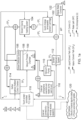
- apparatus 100 includes a removable solvent cartridge 102, a solvent dosing and heating system 104 for containing a solvent, a solvent distribution system 106, a processing chamber 108, a vacuum pump 110, and a solvent recovery system 112.
- the apparatus also includes a control chamber 114 connected to the solvent dosing and heating system 104 and an air heater pump 116 for venting heated air into the processing chamber 108.
- the processing chamber 108 also contains a part support system 109 such as a rack or the like.
- a first control valve V 1 is located between the solvent cartridge 102 and the solvent dosing/heating system 104.
- a second control valve V 2 is located between the solvent dosing/heating system 104 and the solvent distribution system 106.
- a third control valve V 3 is located between the solvent dosing/heating system 104 and the control chamber 114.
- a fourth control valve V 4 is located downstream of the chamber, aptly at the vacuum pump 110, to allow the apparatus, particularly the processing chamber 108, to be selectively vented to atmosphere.
- a fifth control valve V 5 is located between the solvent recovery system 112 and the solvent dosing and heating system 104/solvent cartridge 102.
- Valve V 5 is a diverter valve which selectively controls the flow of recovered solvent to the solvent dosing and heating system 104 or the cartridge 102 as described further below.
- the apparatus 100 further includes a controller 118 having a user interface, e.g. a touchscreen display, to allow an operator to input predetermined parameters associated with the AM part to be post-processed, as will be described further below.
- a controller 118 having a user interface, e.g. a touchscreen display, to allow an operator to input predetermined parameters associated with the AM part to be post-processed, as will be described further below.
- An operator may interact with the controller either at the apparatus or remotely via a wired or wireless connection by using an application stored on a computing device such as a tablet or mobile phone.
- the controller 118 is electrically connected to the controllable components through a computer system such as a Raspberry Pi TM or other open or closed sourced system, to the systems and sensors of the apparatus 100 to allow the controller to automatically and selectively control the apparatus, whilst also receiving feedback signals during a post-processing operation, as described further below.
- the controller is also configured to record apparatus ambient operating conditions, namely ambient temperature AT1 and humidity AH1 while the apparatus is in use.
- the controller is aptly connected to an emergency stop button ES1 to immediately stop the machine should it be required.
- a sensor AP1 is also present to stop the apparatus 100 in the event of any maintenance access panels being removed during operation.
- the controller 118 is also in read/write communication with a data storage medium, such as a cloud-based database 120, to allow operating parameters, programs and data to be accessed and/or stored.
- the flow of solvent in a liquid state during the post-processing operation is shown by a dot-dashed line and referenced SP L .
- the flow of solvent in a vapour state is shown by a relatively thick solid line and referenced SPv.
- the flow of water is referenced WP and the flow of air is referenced A.
- the control links are shown in a relatively thin line and referenced C.
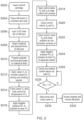
- Figure 2 illustrates a flow diagram showing the steps of a method S200 of post-processing an AM part using the apparatus 100 according to certain embodiments of the present invention.
- a 'pre-packaged' and sealed cartridge 102 containing a suitable solvent is selected and removably coupled to the apparatus 100 via a suitable connection 102c such as a quick release mechanism or the like.
- the solvent cartridge 102 includes two compartments; one for virgin solvent and another for used solvent.
- a sensor SL 1 senses the virgin solvent level and a sensor SL 3 senses the used solvent level.
- the virgin solvent compartment has at least an outlet and the used solvent compartment has at least in an inlet for returning used solvent to the cartridge as described further below.
- the cartridge 102 includes a closed source electronics chip 102a which communicates with the controller 118 to allow sensor signals to be operably sent thereto.
- the cartridge 102 also includes a quick release coupling handle mechanism 102b for handling the cartridge when connecting to and removing from the apparatus.
- the handle mechanism 102b may be coupled to the connection mechanism 102c such that the handle mechanism 102b actuates a quick connect/release coupling mechanism 102c to quickly and easily couple/remove the cartridge to/from the apparatus.
- a sensor QR 1 (not shown) may be provided to confirm to the controller 118 that the cartridge is properly located and connected to the apparatus.
- Suitable solvents include protonic polar solvent and non-proton polar solvents, such as, but not limited to, 1,1,1,3,3,3-hexafluoro-2-propanol (HFIP), dimethylformamide, sulphuric acid, m-cresol, formic acid, trifluoroacetic acid, and benzyl alcohol.
- HFIP 1,1,1,3,3,3-hexafluoro-2-propanol
- dimethylformamide such as 1,1,1,3,3,3-hexafluoro-2-propanol (HFIP), dimethylformamide, sulphuric acid, m-cresol, formic acid, trifluoroacetic acid, and benzyl alcohol.
- HFIP 1,1,1,3,3,3-hexafluoro-2-propanol
- sulphuric acid m-cresol
- formic acid trifluoroacetic acid
- benzyl alcohol benzyl alcohol.
- benzyl alcohol benzyl
- the support structure 109 is configured to ensure the part is fully exposed to solvent introduced into the chamber.
- the access door/lid is closed and the chamber 108 is sealed.
- the chamber 108 is sealed once a process chamber door sensor Do/Dc indicates that the door is closed.
- a systems check is run by the controller 118 to ensure the apparatus 100 is in a 'neutral' state and ready to process AM parts.
- the neutral state check ensures that all control valves are in the correct positions, the solvent cartridge contains a sufficient amount of virgin solvent and has been correctly coupled to the apparatus, and the process chamber door/lid is securely closed.
- a user inputs a digital CAD file into the controller 118 for the AM part to be processed either via the Internet/Ethernet/wireless connection from a program/application or from a database of pre-stored CAD data files.
- the CAD file details the parts to be processed in the orientation and position they are located on the support structure 109 in the processing chamber 108. This ensures repeatability and reproducibility and also allows accurate calculation of processing parameters by understanding the surface area and 'complexity' of the parts.
- the user selects the material of the AM part and the desired surface finish, e.g. roughness, which in turn determines the required processing program to be selected and run by the controller.
- the part material may be selected from a non-exhaustive list of materials including Nylon 12 (PA220 Duraform TM PA), Nylon 11 (Duraform TM EX Natural, Duraform TM EX Black), Thermoplastic Polyurethane (TPU), TPE-210 elastomer materials, ABS, or the like.
- the touchscreen display may list a number of selectable materials for the user to select responsive to the AM part to be post-processed.
- the surface roughness may be selected from a range of around 1.5
- a surface finish may be selected based on finish descriptions, e.g. matt or gloss, and/or visual examples displayed on the display of the user interface or mobile computing device.
- the processing program is selected by the controller 118 in response to the selected part material and desired surface roughness and is then executed.
- the solvent dosing/heating system 104 includes a solvent dosing chamber 104a and a solvent level sensor SL 2 to sense a level of solvent therein, a solvent dosing pump 104b and a pressure sensor Sp 1 to sense a pressure of the solvent being pumped thereby, a further control valve V 1A , and a solvent heating element 104c, such as a heating coil, and a temperature sensor S t1 to sense a temperature of the solvent in the heating system 104.
- the first control valve V 1 is opened by the controller 118 and a predetermined amount of solvent to at least partially fill the chamber 104a of the solvent dosing/heating system 104, aptly around 1000ml, is transferred from the cartridge 102 to the solvent dosing/heating system 104 using the solvent dosing pump 104b at a controlled solvent pump dosing speed SDs.
- the first control valve V 1 is closed.
- a predetermined dose of liquid solvent is transferred from the dosing chamber 104a to the solvent heater coil 104c via valve V1A by the solvent dosing pump 104b.
- the 'dose' of liquid solvent is heated through the solvent heater coil 104c to a predetermined temperature S t1 by suitable heating means, e.g. an electrical heating element located in or around the solvent heater coil 104c.
- suitable heating means e.g. an electrical heating element located in or around the solvent heater coil 104c.
- the solvent quantity is calculated as a function of the type of solvent being used, the volume of the processing chamber 108, the surface area of the part/s, the processing temperature (a function of solvent boiling point) and the processing pressure (vacuum).
- the dosing amount from the solvent dosing chamber through the heating coil is around 25-200ml.
- the cartridge 102 itself may be heated by a separate or integral heating means, such as an electrical heating element disposed in the cartridge, to elevate the temperature of the solvent therein to the predetermined temperature S t1 .
- the solvent dosing/heating system 104 may not be required and the solvent may be introduced into the processing chamber 108 directly from the cartridge instead of via the dosing/heating system 104.
- the solvent is heated to enable a range of solvents with different boiling points to be processed effectively.
- the solvent temperature S t1 may be between room temperature and 100°C depending on the type of solvent to be used for the AM part being processed. Some solvents may not require heating.
- Preheating the solvent to transform it into a vapour phase before it is introduced into the processing chamber 108 allows a lower pressure differential (vacuum) to be applied to the solvent, and therefore less energy, to transform the solvent from a liquid state to a vapour state and draw the solvent vapour into the processing chamber 108.
- the ability to heat the solvent can speed up the thermodynamic process of solvent evaporation.
- a negative pressure is then applied inside the processing chamber 108 by the vacuum pump 110 for a vacuum time VT 1 to create a reduced chamber pressure VP 1 of about around 10-200mbar, and aptly around 70mbar.
- an absolute vacuum may be created in the processing chamber 108.
- the critical pressure as measured by sensor ACP1 in the processing chamber 108 is defined as the point below which the solvent will evaporate at room temperature, i.e. at the critical point when the solvent is in the vapour phase before entering the gaseous phase if the pressure/temperature was increased.
- the second and third control valves V 2 and V 3 are opened and the pressure difference between the solvent dosing/heating system 104 and the processing chamber 108 and the control chamber 114 draws the solvent into both chambers 108,114.
- the 'dose' of solvent is instantly drawn into the processing chamber 108 and the control chamber 114 and instantly fills the chambers 108,114.
- the AM part/s located in the processing chamber 108 and a test coupon/specimen located in the control chamber 114 are fully surrounded by solvent vapour.
- the dosing quantity is controlled by the solvent dosing/heating system 104 and is defined as the amount of solvent required to fully saturate the vapour phase. This is governed by the vapour-liquid equilibria of the specific solvent in relation to the temperature and pressure of the vapour and liquid phases.
- the solvent distribution system 106 includes three distribution channels 106a each having a plurality of apertures equally spaced to ensure even and rapid introduction of the solvent vapour phase into the vacuum process chamber 108.
- a positive pressure may be applied to the solvent to urge the same into the chambers 108,114 from the solvent reservoir 104.
- step 220 the second and third control valves V 2 and V 3 are closed.
- the fourth control valve V 4 is opened and ambient air heated by a suitable heater H1 (not shown) of the heater pump 116 to a predetermined temperature aT is drawn or pumped into the processing chamber 108.
- a suitable heater H1 not shown
- the solvent vapour instantly condenses onto the AM part/s to form a uniform residue and even film of solvent in the liquid state on the part's outer surfaces.
- the second control valve V 2 may be opened to expose the processing chamber 108 to the solvent dosing/heating system 104 and thereby to additional solvent to control the desired condensation rate.
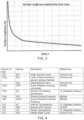
- the condensed liquid solvent film is maintained on the AM part/s for a predetermined part exposure time PET 1 which can range from around 5 seconds for Nylon12 parts to around 10 minutes for TPU type parts. As illustrated in Figure 3 , the predetermined part exposure time PET 1 determines the final surface roughness of the part/s and can be controlled to around 1.5
- the vacuum pump 110 applies a negative pressure VP 2 of about around 10-200mbar to the processing chamber 108 for a predetermined time VT 2 .
- the reapplication of a negative pressure to the processing chamber 108 increases vapour pressure to return the condensed solvent from a liquid state to a vapour state.
- the fourth control valve V 4 is opened and the processing chamber 108 is vented to atmosphere through the vacuum pump 110 and the solvent vapour is fully removed from the surface of the processed AM part/s and from the processing chamber 108 itself.
- a carbon filter is present on the external atmosphere manifold and heater pump to ensure no solvent vapour is released into the atmosphere. No residual vapour remains on the surface of the part/s, no residual trace is left, and in turn the post-processing of the part/s is immediately stopped.
- a solvent sensor SS 1 is located in the processing chamber 108 to sense the presence of solvent vapour therein and send a signal to the controller 118 indicating whether or not solvent exists in the chamber 108.
- the extraction/drying step is repeated until no solvent (Volatile Organic Compounds - VOCs) is detected within the chamber 108 by the solvent sensor SS 1 located therein.
- the solvent vapour extracted from the processing chamber 108 may be passed through a solvent recovery unit 112, which consists of a Peltier module heat pump system or the like.
- the solvent vapour is condensed across the Peltier heat pump system in the solvent recovery system 112 at a predetermined temperature CT1, and the condensed liquid (solvent and water in view of the heated ambient air being introduced into the processing chamber at step S222) is collected in a liquid trap at the bottom of the solvent recovery system 112.
- the liquid (containing both the solvent and water) is then distilled through a heater coil at a temperature HCT1 above the solvent's boiling temperature, but below the water's boiling temperature, i.e. 100°C). This vaporises the solvent, while keeping the water in the liquid phase.
- the re-vaporised solvent is then passed back through the Peltier heat pump to condense from a vapour to a liquid.
- the water is recovered in the waste water container 122.
- a molecular sieve may be used to remove the water from the system.
- the recovered solvent is then returned to the solvent dosing/heating system 104 via the fifth control valve V 5 .
- the apparatus 100 therefore forms a closed loop.
- the solvent is used for around a hundred operations or until a maximum surface area processed has been reached, whichever is sooner, before being recovered and sent to the used solvent compartment of the cartridge 102 via the diverter valve V 5 for safe disposal.
- the electronic chip 102a which is configured to monitor how often solvent is recycled through the cartridge using sensor Nc will automatically communicate with the controller 118 such that a new cartridge is automatically or manually ordered for delivery.
- the used cartridge is removed and a new cartridge containing 'fresh' solvent is inserted for the next operation.
- the water product from the distillation is directed to a waste water container 122 for safe collection and disposal by the operator.
- the waste water container 122 includes a water level sensor WL1 (not shown) to indicate when the container needs emptying or replacing.
- step S230 in response to signal SS 1 indicating no solvent vapour remains in the processing chamber 108, the controller 118 stops the vacuum pump 110 and closes the fourth valve V 4 .
- the processing program ends and the operator is notified by an audible and/or visual indication.
- step S232 the access door of the apparatus 100 is opened to retrieve the post-processed AM polymer part/s from the processing chamber 108. The process is repeated as desired.
- a test coupon 114b e.g. a dog bone specimen, which is made by the same AM process and from the same material as the AM part/s being processed is located in the control chamber 114 which is not subject to a vacuum and is thus subject to potential water uptake from the surrounding atmosphere.
- the test coupon is subjected to the solvent vapour for the same solvent exposure time of PET1 as the AM part being processed and the weight of the test coupon is continually monitored by suitable means, such as a load cell 114c.
- suitable means such as a load cell 114c.
- the original part weight calculated from the CAD data (under vacuum and without water uptake) is compared to a test coupon outside the vacuum chamber (not under vacuum and subject to water uptake).
- the test samples require the same surface area to volume ratio as the part being smoothed in order to provide accurate feedback.
- the relationship between sample weight increase as a function of solvent exposure time PET1 is used to calculate the actual achieved surface roughness.
- the correlation therebetween is generated through experimental feedback and results from iterative testing for a known sample quantity and surface finish per type of material.
- a non-contact optical method such as laser measurement and/or a white light interferometer or laser scanning confocal microscope could be used on the sample part in the control chamber 114 to determine surface roughness changes in real time. In this manner, it is possible to continuously assess if the AM part/s being smoothed in the processing chamber 108 and to ensure that the parts have been processed to the correct surface roughness.
- the processing parameters may be adjusted in real time and the AM part/s in the processing chamber 108 will automatically be processed again until the desired surface roughness is achieved.
- Opening valve V3a (as shown in Figure 1e ) at the end of the process allows the control chamber 114 to be exposed to the vacuum in the processing chamber 108 thus safely evacuating any solvent vapour and removing any solvent present on the surface of the sample located therein.
- the controller 118 monitors and logs all the operating variables as listed in the tables of Figures 4 to 6 and uploads them to a read/write database stored on a web-based server 120 or the like.
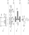
- apparatus 400 for post-processing an AM part includes a removable reservoir 402, a solvent dosing and heating system 404, a solvent distribution system 406, an AM part processing chamber 408, a vacuum pump 410, and a solvent recovery system 412.
- the solvent dosing and heating system 404 includes a peristatic pump 405 and a valve 407 to selectively deliver a predetermined amount/dose of solvent from the reservoir 402 to the processing chamber 408 via the solvent distribution system 406.
- the solvent dosing and heating system 404 further includes a solvent flow meter 409 and a heating element 411 in the form of a heating plate or coil.
- a thermocouple 413 is provided at the heating element 411 to monitor a temperature ST1 thereof.
- the solvent distribution system 406 ensures solvent vapour is distributed evenly across the chamber 408. It consists of at least one distribution channel with an aperture located, preferably centrally, within the process chamber 408. Aptly, one aperture is provided per approximately 30 litres of effective process chamber volume. For a process chamber having a volume of greater than around 30 litres, more apertures are desirable to ensure the process conditions for polymer components situated at different locations within the chamber are the same. For example, a process chamber 408 having an effective volume of around 90 litres would require at least three apertures distributing solvent vapour across the chamber.
- valve 471 to extract a liquid solvent sample out of the machine 400 for testing purposes.
- the processing chamber 408 includes a removable lid 415 and a part support system 417 for supporting one or more AM parts to be post-processed, such as a rack, hooks, frame, or the like.
- the inner walls of the processing chamber 408 are aptly heatable by a suitable heating element/s and a thermocouple 451 is provided to monitor a temperature CT1 thereof.
- the lid 415 is also aptly heatable by a suitable heating element/s and a thermocouple 421 is provided to monitor a temperature thereof.
- a pressure sensor 423 is provided to monitor a pressure inside the processing chamber 408 and a temperature sensor, e.g. a further thermocouple, 419 is provided to monitor a temperature therein.
- a switch/sensor 425 is also provided to sense a state of the lid relative to the processing chamber, i.e. open or closed.
- Further thermocouples 453,455, or the like, are provided inside and outside the apparatus to monitor internal and external ambient temperatures, and a humidity sensor 457 monitors ambient humidity.
- a pair of control valves 427a,427b are provided between the processing chamber 408 and a stack of activated carbon filters 416 to allow the apparatus, particularly the processing chamber 408, to be selectively vented to atmosphere.
- One of the valves is to allow a relatively small vent to atmosphere whilst the other valve is to allow a relatively large, e.g. complete, vent to atmosphere.
- a second valve 429 is located between the processing chamber 408 and the vacuum pump 410 for selectively recovering solvent from the processing chamber 408.
- Pump thermocouples 459,461,463 are also provided to monitor a temperature of the pump body and at the inlet and outlet thereof.
- a condenser valve 431 is provided between the vacuum pump 410 and the solvent recovery system 412 to isolate the vacuum pump for maintenance purposes.
- Condenser thermocouples 465,467 are provided at the inlet and outlet of the solvent recovery system 412, and inside the condenser, and a pressure sensor 469 is also provided to monitor a pressure within the condenser.
- a second peristatic pump 433 is provided between the solvent recovery system 412 and the solvent reservoir 402 for returning recovered solvent from the solvent recovery system 412 to the reservoir 402.
- a further control valve 435 is provided between the second peristatic pump 433 and the solvent recovery system 412 and a used solvent flow meter 437 is provided downstream of the pump 433.
- a further valve 473 is provided between the condenser 412 and the reservoir 402 to extract a sample of the recovered solvent for testing purposes.
- a condenser air valve 439 is provided between the solvent recovery system 412 and the stack of filters 416. Furthermore, a chilled air valve 441 is provided between the solvent recovery system 416 and the processing chamber 408.
- a further control valve may be located between solvent dosing and heating system 404 and the processing chamber 408.
- the solvent dosing and heating system 404 would act as a high pressure vessel able to preheat solvent in liquid or vapour phase to a particular temperature before releasing it into the processing chamber.
- the apparatus 400 further includes a controller 418 having a user interface, e.g. a touchscreen display, to allow an operator to input predetermined parameters associated with the AM part to be post-processed, as will be described further below.
- a controller 418 having a user interface, e.g. a touchscreen display, to allow an operator to input predetermined parameters associated with the AM part to be post-processed, as will be described further below.
- An operator may interact with the controller either at the apparatus or remotely via a wired or wireless connection by using an application stored on a computing device 463 such as a tablet or mobile phone.
- the controller 418 is electrically connected to the controllable components of the apparatus 400 through a computer system such as a Raspberry Pi TM or other open or closed sourced system, to the systems and sensors of the apparatus 400 to allow the controller to automatically and selectively control the apparatus, whilst also receiving feedback signals during a post-processing operation, as described further below.
- the controller is also configured to record apparatus ambient operating conditions, namely ambient temperature and humidity while the apparatus is in use.
- the controller is aptly connected to an emergency stop switch/button (signal EM1 - see table of Figure 10 ) to immediately stop the machine should it be required.
- a sensor (signal AP1) may also be present to stop the apparatus 400 in the event of any maintenance access panels being removed during operation.
- the controller 418 may also be in read/write communication with a data storage medium, such as a cloud-based database, to allow operating parameters, programs and data to be accessed and/or stored.
- Figure 8 illustrates a flow diagram showing the steps of a method of post-processing an AM part using the apparatus 400 as illustrated in Figure 7 according to certain embodiments of the present invention.
- a 'pre-packaged' and sealed reservoir 402 containing a suitable solvent is selected and removably coupled to the apparatus 400 via a suitable connection such as a quick release mechanism or the like.
- the solvent reservoir 402 includes two compartments 420,422; one for virgin solvent and another for used/recovered solvent.
- a level sensor 443 senses the virgin solvent level in the virgin solvent compartment and a level sensor 445 senses the used solvent level in the used solvent compartment.
- the virgin solvent compartment 420 has at least an outlet and the used solvent compartment has at least an inlet for returning used solvent to the cartridge, as described further below.
- the cartridge 402 includes a closed source electronics chip which communicates with the controller 418 to allow sensor signals to be operably sent thereto.
- the cartridge 402 also may include a quick release coupling handle mechanism for handling the cartridge when connecting to and removing from the apparatus.
- the handle mechanism may be coupled to the connection mechanism such that the handle mechanism actuates a quick connect/release coupling mechanism to quickly and easily couple/remove the cartridge to/from the apparatus.
- a sensor may be provided to confirm to the controller 418 that the cartridge is properly located and connected to the apparatus.
- Suitable solvents include protonic polar solvent and non-proton polar solvents, such as, but not limited to, 1,1,1,3,3,3-hexafluoro-2-propanol (HFIP), dimethylformamide, sulphuric acid, m-cresol, formic acid, trifluoroacetic acid, and benzyl alcohol.
- HFIP 1,1,1,3,3,3-hexafluoro-2-propanol
- dimethylformamide such as 1,1,1,3,3,3-hexafluoro-2-propanol (HFIP), dimethylformamide, sulphuric acid, m-cresol, formic acid, trifluoroacetic acid, and benzyl alcohol.
- HFIP 1,1,1,3,3,3-hexafluoro-2-propanol
- sulphuric acid m-cresol
- formic acid trifluoroacetic acid
- benzyl alcohol benzyl alcohol.
- benzyl alcohol benzyl
- the support structure 417 is configured to ensure the part is fully exposed to solvent introduced into the chamber.
- the access lid 415 is closed and the chamber 408 is sealed.
- a processing chamber door sensor 425 indicates that the lid is closed and the processing chamber is sealed.
- a corresponding signal L1 (see table of Figure 10 ) from the lid sensor 425 indicating the lid is closed is detected by the controller 418.
- a systems check is run by the controller 418 to ensure the apparatus 400 is in a 'neutral' state and ready to post-process AM parts.
- the neutral state check ensures that all control valves are in the correct positions, the solvent cartridge contains a sufficient amount of virgin solvent and has been correctly coupled to the apparatus, and the process chamber door/lid is securely closed.
- a user inputs information relating to the AM part to be post-processed into the controller 418.
- the information includes, but is not limited to, material, surface area, volume, geometry, complexity and/or orientation/position within the processing chamber.
- the part material may be selected from a non-exhaustive list of materials including Nylon 12 (PA220 Duraform TM PA), Nylon 11 (Duraform TM EX Natural, Duraform TM EX Black), Thermoplastic Polyurethane (TPU), TPE-210 elastomer materials, Acrylonitrile butadiene styrene (ABS), Acrylonitrile styrene acrylate (ASA), or the like.
- the user selects the desired surface finish, e.g. smoothness/roughness, which, together with input parameters from step S406, determines the required processing program to be selected and run by the controller (see table of Figure 11 ).
- the surface roughness may be selected from a range of around 1.0 ⁇ m to the ⁇ as printed' surface roughness (i.e. no smoothing).
- a surface finish may be selected based on finish descriptions, e.g. matt or gloss, and/or visual examples displayed on the display of the user interface or mobile computing device.
- the processing program is selected by the controller 418 in response to the selected part material and desired surface roughness and is then executed.
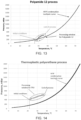
- the processing programs are defined according to the required levels of energy to be equalised to process particular materials (see table of Figure 11 , and graphs of Figures 13 and 14 ), as described further below.
- the energy to be equalised depends on the solvent, the material, the desired smoothness, and in turn the required temperature differences between the material and the solvent. The higher the temperature difference, the higher the energy to be equalised.
- T H is the temperature of HFIP vapour
- T M is the temperature of the polymer to be processed.
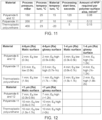
- T M values were derived by the applicant and are provided in Figure 11 .
- T H values depend on the process conditions derived by the applicant as tabulated in Figure 11 and are derived accordingly from the Pressure-Temperature graph of the specific solvent (e.g. Figure 15 for the HFIP solvent).
- the vacuum pump 410 is used to reduce the pressure within the processing chamber 408, and the chamber wall heaters 403 preheat inner walls of the chamber to a predefined temperature.
- the pressure and temperature of the processing chamber 408 are based on the AM polymer part to be processed (see table of Figure 11 ).
- Figures 13 and 14 show the solvent-specific thermodynamic relationships for Polyamide 12 and Thermoplastic Polyurethane respectively.
- the solvent dosing valve 407 of the solvent dosing and heating system 404 is opened by the controller 418 and a predetermined amount/dose of solvent (see table of Figure 11 ) is transferred from the reservoir 402 to the heating element 411 within the solvent dosing/heating system 404 using the solvent dosing pump 405 at a controlled solvent pump dosing speed SDs (see table of Figure 10 ).
- the solvent quantity is calculated as a function of the type of solvent being used, the volume of the processing chamber 108, the surface area of the part/s, and the material of the parts (see table of Figure 11 ).
- the solvent within the solvent dosing/heating system 404 is then heated (provided with energy) to a predetermined temperature St1 (see table of Figure 10 ).
- the amount of energy (heat) provided to the solvent depends on the thermodynamic conditions of the process, which in turn is dictated by the type of polymer to be processed (see tables of Figures 10 and 11 ).
- the solvent has to follow a particular thermodynamic path and condense on the polymer under specific conditions for the surface of the polymer to process.
- the solvent temperature St1 in the solvent dosing/heating system 404 may be between room temperature and 100°C depending on the type of solvent to be used for the AM part being processed (see Figure 9 showing the thermodynamic graph for the HFIP solvent). Some solvents may not require heating. As a result, the solvent is turned into vapour state and is delivered into the processing chamber 408 via the solvent distribution system 406.
- the solvent distribution system 406 includes at least one distribution channel having a at least one aperture located preferably centrally in the chamber to ensure even and rapid introduction of the solvent vapour therein.
- the number of apertures located across the chamber depends on the size of the chamber, with larger chambers requiring more apertures to ensure solvent vapour covers all polymer parts located therein uniformly. It was determined by the applicant that one centrally located aperture is sufficient to uniformly distribute solvent vapour across a processing chamber having a volume of around 30 litres.
- the cartridge 402 itself may be heated by a separate or integral heating means, such as an electrical heating element disposed in the cartridge, to elevate the temperature of the solvent therein to the predetermined temperature St1.
- the solvent dosing/heating system 404 may not be required and the solvent may be introduced into the processing chamber 408 directly from the cartridge via the solvent distribution system 406.
- Another alternative may be a pressure expansion type of device where the solvent dosing/heating system 404 is isolated by the valves from both the reservoir 402 and the processing chamber 408.
- the solvent dosing/heating system 404 becomes a high-pressure vessel where the solvent is heated until it reaches vapor state, then the vapor is superheated and is further provided with energy that in turn increases the pressure within the solvent dosing/heating system 404.
- a valve separating the solvent dosing/heating system 404 and the processing chamber 408 is then opened and the pressure difference between the solvent dosing/heating system 404 with superheated vapor and the processing chamber 408 drives the vapor into the processing chamber 408.
- the apparatus allows for the combination of the pre-heated solvent vapour and the higher or lower pressure in the processing chamber 108 to be achieved.
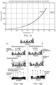
- the temperature of the AM polymer material may also be selectively controlled by precooling using chilled air, or the like, delivered into the processing chamber 408 from, for example, the condenser/solvent recovery system 412 and via the control valve 441 located therebetween. This in turn allows various energy level differences (i.e. temperature gradients) to be achieved between the solvent vapour and the AM polymer part for different AM polymer parts, as shown in Figures 16a & 16b .
- E q is set to be relatively high by increasing the temperature of the solvent vapour T H and reducing the temperature of the AM polymer part to be processed T M ; and b) when E q is set to be relatively low.
- E q is relatively high
- more solvent will rapidly condense on the surface of the part which will result in more dissolution on the material surface and therefore a smoother surface.
- E q is relatively low
- less solvent will condense on the material surface which will lead to less dissolution and a less smooth surface.
- the AM part/s located therein are fully surrounded by solvent vapour.
- the dosing quantity is controlled by the solvent dosing/heating system 404 and is determined according to the processing requirements of the particular AM polymer part and/or as the amount of solvent required to fully saturate the vapour phase. In the latter case, this is governed by the vapour-liquid equilibria (e.g. see Figure 15 for the HFIP vapourliquid graph) of the specific solvent in relation to the temperature and pressure of the vapour and liquid phases.
- the solvent starts to condense on the AM polymer part located in the processing chamber 408.
- the condensation is triggered due to the pressure and/or temperature conditions and the resulting vapour oversaturation governed by the vapor-liquid equilibrium line for the particular solvent (see Figure 15 ).
- This is manipulated by various methods: lowering the temperature within the processing chamber 408 using the chamber heater 403; increasing the pressure by introducing more solvent vapor into the processing chamber 408 via the solvent dosing/heating system 404 or opening the vent-to-air valves 427a,b (see Figures 13,14 and 17).
- Figure 17 illustrates the processing effects of controlling the pressure and temperature of the solvent in the processing chamber 408 and on the AM part/s.
- Figure 18a illustrates the absorption of the condensed solvent droplets into the porous polymer matrix caused by the capillary pressures of the pores, which undesirably occurs under standard conditions by conventional methods; and Figure 18b illustrates condensed solvent droplets rapidly accumulating on the surface of the porous polymer faster than absorption can take place, which is desirably achieved in accordance with certain embodiments of the present invention.
- the amount of condensed solvent per unit of time depends on the level of energy E q to be equilibrated between the polymer and the solvent vapour. More solvent condensed per unit of time will result in bigger dissolution of the outer layer of the polymer part, hence a smoother surface; and, in contrast, a lower amount of solvent condensation on the surface will dissolve less of the surface which in turn means a less smooth surface finish.
- Thermodynamic conditions in the processing chamber 408 for the optimum energy to be equilibrated E q were derived by the applicant and vary for different polymers (see tables of Figures 11 and 12 and the graphs of Figures 13 and 14 ).
- Condensation may also be triggered by the addition of inert gasses using additional storing chambers for those gasses to increase the pressure or addition of cooled air to reduce the temperature.
- the temperature of these walls is controlled to be just above the condensation line of the solvent (see Figures 15 and 17 ).
- the condensation of solvent vapor desirably occurs only on the AM polymer part/s.
- the condensed liquid solvent film is maintained on the AM part/s for a predetermined part exposure time PET 1 , which can range from around 5 seconds for Nylon12 parts to around 10 minutes for TPU type parts (see table of Figure 12 ).
- the predetermined part exposure time PET 1 and the level of the energy to be equilibrated E q determines the final surface roughness of the part/s and can be controlled to around 1.0 ⁇ m (see table of Figure 12 and Figure 16a,b ).
- Figures 13 and 14 represent the process for Polyamide 12 (Nylon 12) and TPU materials respectively in terms of pressure - temperature conditions within the processing chamber.
- the part smoothing process is complete.
- the time required to achieve various levels of surface finish in accordance with certain embodiments of the present invention can be seen in the table of Figure 12 .
- Figure 3 illustrates the relationship between surface roughness and exposure time according to certain embodiments of the present invention.
- Vacuum pump 410 then applies a negative pressure VP1 of around 10-200mbar to the processing chamber 408 for a predetermined time VT1.
- the reapplication of a negative pressure to the processing chamber 108 increases vapour pressure to return the condensed solvent from a liquid state to a vapour state. This is done to dry the processed part and recover any excess solvent (see Figure 19a,b ).
- Step S422 the valve 429 between vacuum pump 410 and the solvent recovery system 412 is opened and the solvent vapor is fully removed from the processing chamber 408 through the solvent recovery system 412 where the solvent is collected in a liquid form and transferred to the recovered solvent compartment 422 of the reservoir 402 by the peristatic pump 433.
- Solvent recovery system 412 may comprise a condenser with at least one column, or the like.
- the apparatus 400 therefore forms a closed loop.
- the solvent is used until a maximum surface area processed has been reached, before being recovered and sent to the used/recovered solvent compartment 422 of the reservoir 402 for safe disposal.
- an electronic chip which is configured to monitor how often solvent is recycled through the reservoir, will automatically communicate with the controller 418 such that a new reservoir is automatically or manually ordered for delivery.
- the used reservoir is removed and a new reservoir containing 'fresh' solvent is inserted for the next operation.
- the carbon filter/s 416 is present on the external atmosphere manifold to ensure no solvent vapour is released into the atmosphere. No residual vapour remains on the surface of the part/s, no residual trace is left, and in turn the post-processing of the part/s is immediately stopped. This not only ensures the process is fully controlled, but also some applications, such as for medical or dental devices, require the parts to be fully clean and safe to use, and also to possess a particularly accurate surface roughness which would not be achievable if any further processing of the part occurred as a result of any remaining solvent residue on the surfaces of the part.
- a solvent sensor (not shown) may be located in the processing chamber 408 to sense the presence of solvent vapour therein and send a signal to the controller 418 indicating whether or not solvent exists in the chamber 408.
- the extraction/drying step is repeated until no solvent (Volatile Organic Compounds - VOCs) is detected within the processing chamber 408 by the solvent sensor SS 1 located therein.
- step S426 in response to signal SS 1 indicating no solvent vapour remains in the processing chamber 408, the controller 418 stops the vacuum pump 410 and closes the valve 429 between the processing chamber 408 and the vacuum pump 410.
- the processing program ends and the operator is notified by an audible and/or visual indication.
- the access door/lid 415 of the apparatus 400 may be opened to retrieve the post-processed AM polymer part/s from the processing chamber 408. The process is repeated as desired.
- the controller 418 monitors and logs all the operating variables as indicated in the tables of Figures 9 and 10 and uploads them to a read/write database stored on a web-based server or the like.
- a set of predetermined algorithms defining the various relationships between the operating parameters are selected and used to control the post-processing of an AM part based on its material, volume, surface area, geometry, and the desired finish, as outlined above.
- the required surface roughness is input into the controller along with the part material type.
- the controller calculates the required part exposure time PET1 in accordance with the relationship between surface roughness and time shown in Figure 3 .
- E q k ⁇ (T H - T M ) / T H
- k coefficient representing heat transfer of different polymers
- T H is the temperature of HFIP vapour
- T M is the temperature of the polymer to be processed.
- Relatively high E q results in rapid condensation of solvent vapour on the AM polymer part and glossy surface finish, whereas relatively low E q results in slower condensation speed and a matt surface finish (see Figure 16a,b ).
- the predetermined algorithms are used by the controller to automatically control the key variables of the automated process to achieve the user's desired surface finish.
- apparatus having a processing chamber 408 of around 400mm high, around 400mm deep and around 600mm wide can enable batch processing of an AM polymer part having dimensions of about around 31 ⁇ 31 ⁇ 53mm in approximately 20 seconds and thus processing of around 50 parts in around 12 minutes which is over 100 times quicker than the traditional, manual methods for post-processing an AM polymer part.
- the post-processing method comprises selectively releasing a predetermined amount of 1,1,1,3,3,3-Hexafluoro-2-propanol (HFIP) solvent into the processing chamber using positive or negative pressure.
- HFIP 1,1,1,3,3,3-Hexafluoro-2-propanol
- the amount of HFIP solvent required depends on the type and number of AM polymer parts to be processed.
- the method comprises providing solvent predetermined amount of energy and heating it to a specific temperature, which causes the solvent to vaporise prior to entering the processing chamber.
- the apparatus and method according to certain embodiments of the present invention are configured to create an energy (heat) potential between the AM polymer part and the HFIP solvent: the solvent is provided with a particular amount of energy and is vaporised, whereas the AM polymer part may be pre-cooled to a particular temperature so that there is an energy difference (entropy) between the solvent vapour and the AM polymer part.
- Liquid HFIP is turned into a vapor and then is rapidly condensed on the surface of the polymer material. Due to the energy difference between the solvent vapour and the AM polymer part, the polymer material is not fast enough to absorb the solvent condensate droplets within its matrix, instead solvent condensate droplets accumulate on the upper layer of the polymer.
- the polymer grains in the upper layer are dissolved and redistributed to form a smooth boundary layer.
- the material particles coalesce and the upper layer is sealed, preventing solvent intrusion/absorption deeper into the polymer matrix.
- Thermodynamic energy conditions for enough condensate to be created on the part surface vary for different AM polymers.
- This particle surface sealing effect may in turn have further applications in water-sealing applications.
- the condensation speed is aptly increased relative to condensation under standard conditions to ensure the polymer surface is processed. The reason for this is the porous structure of the polymer surface, which results in the gradual absorption of the condensate droplets, i.e. sponge-water absorbing behaviour.
- the elastomers such as Thermoplastic Polyurethane (TPU). Due to this adsorption phenomena rather than accumulating on the surface of the polymer, solvent would normally be absorbed within the polymer matrix. However, by increasing condensation speed the porous polymer is not able to absorb condensation droplets fast enough, as a result the condensation droplets accumulate on the surface of the polymer rather than be absorbed, which in turn dissolves and smoothens the surface of the AM polymer part. In the closed system (processing chamber) the availability of energy to be equilibrized during the process has to be increased, i.e. the entropy of the system reduced. This in turn increases the condensation speed.
- TPU Thermoplastic Polyurethane
- the temperature of the HFIP is increased using in-built heating system, whereas the polymer materials may be cooled using either in-built or external blast-freezing system. Pressure within the chamber is also manipulated to help achieve the required difference in the energy to be equilibrated.
- T M values were derived by the applicant and are provided in Figure 11 .
- T H values depend on the process conditions derived by the applicant as tabulated in Figure 11 and are derived accordingly from the Pressure-Temperature graph of the specific solvent (e.g. Figure 15 for the HFIP solvent).
- the processing chamber walls are aptly kept above the HFIP condensation conditions to ensure the condensation happens preferentially on the polymer parts instead of the chamber itself.
- the HFIP is converted back into the vapor phase to remove it from the polymer.
- a vacuum is applied to help residual solvent be removed from the processed polymer.
- the amount of HFIP getting into the matrix of the polymer material is minimized by fast condensation process. As a result, the polymer grains in the upper surface coalesce and act as a sealing boundary layer.
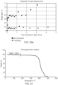
- Figure 22 illustrates thermogravimetric results of the processed polymer material, indicating the presence of residual HFIP and the temperature at which it can be recovered.
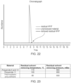
- Figure 23 illustrates a chromatograph showing the efficiency of recovery of the HFIP from the processed polymer.
- the solid grey line represents the amount of leftover HFIP in the processed polymer that has not undergone solvent removal procedure, whereas the solid black line indicates the amount of leftover HFIP in the processed polymer sample that has undergone solvent removal procedure.
- the dashed black line is provided for reference and shows amount of leftover HFIP in non-processed polymer sample. This ensures there is no unwanted weight gain or residual chemicals in the AM polymer part.
- Thermogravimetric analysis and chromatography experiments were carried out to find the most effective processing chamber temperature-vacuum parameter combination that recovers residual solvent (see table of Figure 24).
- HFIP 1,1,1,3,3,3-Hexafluoro-2-propanol
- AM additively manufactured
- Apparatus in accordance with certain embodiments of the present invention is configured to manipulate the thermodynamic system and create favourable energy conditions for the AM polymers to be smoothed.
- the apparatus and processing method are configured to treat the surface of several polymer parts manufactured by additive manufacturing methods (e.g. 3D printing). The surface of treated polymers becomes smoother compared to non-treated surfaces and, in particular, the smoothness level can be controlled with a set of predefined parameters as described herein.
- HFIP condensate treats the surface of the polymer material in the quick process which is achieved by maximizing the energy to be equilibrated (entropy) between HFIP and the polymer, i.e. heating up the HFIP while cooling polymer material.
- a new use of HFIP is provided by treating the surface of the polymers, particularly TPU, by HFIP condensation on the polymer through control of available equilibration energy between HFIP and the polymer material.
- the apparatus is configured to process any polymer part made from a 3D printing/additive manufacturing process.
- the apparatus is able to process parts created from multiple polymer groups such as Nylon 12 (PA220 Duraform TM PA), Nylon 11 (Duraform TM EX Natural, Duraform TM EX Black), Thermoplastic Polyurethane (TPU), and TPE-210 elastomer materials, or the like.
- the apparatus is able to process other polymer materials such as ABS.
- An AM part made by fused deposition modelling (FDM), laser sintering (LS), and high speed sintering (HSS) and multi-jet fusion can be finished using the apparatus and method according to certain embodiments of the present invention.
- FDM fused deposition modelling
- LS laser sintering
- HSS high speed sintering
- the processing method according to the present invention may desirably seal the surface of porous materials, such as TPU and Polyamide 12, which might be advantageous where the AM part is to be used in water-sealing applications or where water tightness of the material is particularly important (see Figures 20a & 20b ). This particle surface sealing effect may in turn have further applications in water-sealing applications.
- the processing method according to the present invention may also desirably improve the tensile strength of the AM polymer part/s.
- control of the drying step of the processing method according to certain embodiments of the present invention desirably avoids continued processing of an AM part which would otherwise occur due to the presence of unevaporated solvent on the part's surface.
- the applications for the apparatus and method according to certain embodiments of the present invention are wide ranging, and may be suitable for processing any AM part which requires a desired finish for aesthetic and/or functional purposes, such as footwear, automotive interior/trim components, and dental/medical devices, or the like.
Landscapes
- Chemical & Material Sciences (AREA)
- Engineering & Computer Science (AREA)
- Manufacturing & Machinery (AREA)
- Materials Engineering (AREA)
- Physics & Mathematics (AREA)
- Mechanical Engineering (AREA)
- Optics & Photonics (AREA)
- Treatments Of Macromolecular Shaped Articles (AREA)
- Processing And Handling Of Plastics And Other Materials For Molding In General (AREA)
- Sampling And Sample Adjustment (AREA)
Claims (15)
- Vorrichtung zur Nachbearbeitung eines additiv hergestellten Polymerteils, umfassend:ein Reservoir (102) für ein flüssiges Lösungsmittel;eine Bearbeitungskammer (108), die in einer steuerbaren Fluidverbindung mit dem Reservoir (102) steht; undeine Steuereinheit (118), die dazu eingerichtet ist, ein sich in der Bearbeitungskammer (108) befindendes additiv hergestelltes Polymerteil in Reaktion auf wenigstens einen dem Teil zugeordneten Parameter mit dem Lösungsmittel steuerbar nachzubearbeiten,dadurch gekennzeichnet, dass die Vorrichtung ferner ein Lösungsmittel-Abgabesystem (104) umfasst, das der Bearbeitungskammer (108) vorgeschaltet ist und durch die Steuereinheit (118) betriebsmäßig steuerbar ist, um wahlweise Lösungsmittel aus dem Reservoir (102) zu beziehen und eine vorgegebene Lösungsmittelmenge in die Bearbeitungskammer (108) einzuleiten,ein Heizelement (104c), das dazu eingerichtet ist, die vorgegebene Lösungsmittelmenge auf eine vorgegebene Lösungsmitteltemperatur zu erwärmen, um zu bewirken, dass das Lösungsmittel vor Eintritt in die Bearbeitungskammer (108) verdampft, undeine Vakuumpumpe (110) die durch die Steuereinheit (118) betriebsmäßig steuerbar ist und die dazu eingerichtet ist, an den Innenraum der Bearbeitungskammer (108) einen Unterdruck anzulegen.
- Vorrichtung nach Anspruch 1, wobei die Steuereinheit (118) dazu eingerichtet ist, wahlweise die Vakuumpumpe (110) für eine vorgegebene Zeit zu betreiben, um in der Bearbeitungskammer (108) einen Unterdruck auszuüben.
- Vorrichtung nach Anspruch 1 oder 2, ferner umfassend ein Lösungsmittel-Abgabeventil (V2), das durch die Steuereinheit (118) betriebsmäßig steuerbar ist, um zu ermöglichen, dass wahlweise eine vorgegebene Lösungsmittelmenge durch den in der Bearbeitungskammer (108) ausgeübten Unterdruck in die Bearbeitungskammer (108) gesaugt wird.
- Vorrichtung nach einem der vorangehenden Ansprüche, ferner umfassend eine Heizeinrichtung (403) für eine gesteuerte Erwärmung eines Innenraums der Bearbeitungskammer (108) auf eine vorgegebene Kammertemperatur, wobei die Heizeinrichtung (403) optional ein Heizelement umfasst, das dazu eingerichtet ist, zumindest eine Innenfläche der Bearbeitungskammer (108) steuerbar zu erwärmen.
- Vorrichtung nach einem der vorangehenden Ansprüche, ferner umfassend eine Kühleinrichtung zum gesteuerten Kühlen eines additiv hergestellten Teils, das sich in der Bearbeitungskammer (108) befindet.
- Vorrichtung nach einem der vorangehenden Ansprüche, wobei die Steuerung (118) dazu eingerichtet ist, die Vakuumpumpe (110) wahlweise für eine weitere vorgegebene Zeit zu betreiben, um nach Verstreichen einer vorgegebenen Bearbeitungszeit erneut einen Unterdruck in der Bearbeitungskammer (108) auszuüben.
- Vorrichtung nach einem der vorangehenden Ansprüche, wobei die Vakuumpumpe (110) ferner dazu eingerichtet ist, die Bearbeitungskammer (108) wahlweise zur Atmosphäre zu entlüften, wenn erneut ein Unterdruck ausgeübt wurde, um Lösungsmitteldampf aus der Bearbeitungskammer (108) und dem sich darin befindenden Teil zu extrahieren, und wobei die Vorrichtung ferner optional ein Lösungsmittel-Rückgewinnungssystem (112) umfasst, um gebrauchtes Lösungsmittel aus der Bearbeitungskammer (108) zurückzugewinnen.
- Verfahren zur Nachbearbeitung eines additiv hergestellten Polymerteils, umfassend:Anordnen eines additiv hergestellten Polymerteils in einer Bearbeitungskammer (108);Erwärmen einer vorgegebenen Lösungsmittelmenge auf eine vorgegebene Lösungsmitteltemperatur, um zu bewirken, dass das Lösungsmittel vor Eintritt in die Bearbeitungskammer (108) verdampft;Anlegen eines Unterdrucks an einen Innenraum der Bearbeitungskammer (108) für eine vorgegebene Zeit;wahlweise Abgabe der vorgegebenen Lösungsmittelmenge in die Bearbeitungskammer (108);steuerbares Nachbearbeiten des Teils mit dem steuerbar in die Bearbeitungskammer (108) geleiteten Lösungsmittel in Reaktion auf zumindest einen dem Teil zugeordneten Parameter.
- Verfahren nach Anspruch 8, ferner umfassend die Anwendung des Unterdrucks, um wahlweise die vorgegebene Lösungsmittelmenge in die Bearbeitungskammer (108) abzugeben.
- Verfahren nach Anspruch 8 oder Anspruch 9, ferner umfassend wahlweises Erwärmen eines Innenraums der Verarbeitungskammer (108) auf eine vorgegebene Kammertemperatur, wobei das Verfahren optional das Erwärmen von zumindest einer Innenfläche der Bearbeitungskammer (108) umfasst.
- Verfahren nach einem der Ansprüche 8, 9 oder 10, ferner umfassend das Schaffen eines Energiepotentials zwischen einem sich in der Bearbeitungskammer (108) befindenden additiv hergestellten Teil und dem Lösungsmittel.
- Verfahren nach Anspruch 11, ferner umfassend wahlweises Kühlen eines sich in der Bearbeitungskammer (108) befindenden additiv hergestellten Teils, um das Energiepotential zu schaffen und zu bewirken, dass der Lösungsmitteldampf an dem additiv hergestellten Teil kondensiert.
- Verfahren nach einem der Ansprüche 8 bis 12, ferner umfassend erneutes Anwenden eines Unterdrucks in der Bearbeitungskammer (108) für eine vorgegebene Zeit nach dem Verstreichen einer vorgegebenen Bearbeitungszeit.
- Verfahren nach Anspruch 13, ferner umfassend wahlweises Entlüften der Bearbeitungskammer (108) zur Atmosphäre, wenn der Unterdruck erneut ausgeübt wurde, um Lösungsmitteldampf aus der Bearbeitungskammer (108) und dem sich darin befindenden Teil zu extrahieren, wobei das Verfahren ferner optional die Rückgewinnung gebrauchten Lösungsmittels aus der Bearbeitungskammer (108) umfasst.
- Computerprogramm mit Anweisungen, die bei Ausführung in der Steuereinheit der Vorrichtung nach einem der Ansprüche 1 bis 7 die Vorrichtung zur Durchführung des in einem der Ansprüche 8 bis 14 beanspruchten Verfahrens veranlassen.
Applications Claiming Priority (2)
| Application Number | Priority Date | Filing Date | Title |
|---|---|---|---|
| GBGB1700346.8A GB201700346D0 (en) | 2017-01-09 | 2017-01-09 | Improvements to additive manufacturing |
| PCT/GB2017/053841 WO2018127683A1 (en) | 2017-01-09 | 2017-12-20 | Improvements to additive manufacturing |
Publications (2)
| Publication Number | Publication Date |
|---|---|
| EP3565712A1 EP3565712A1 (de) | 2019-11-13 |
| EP3565712B1 true EP3565712B1 (de) | 2023-09-06 |
Family
ID=58463665
Family Applications (1)
| Application Number | Title | Priority Date | Filing Date |
|---|---|---|---|
| EP17822750.0A Active EP3565712B1 (de) | 2017-01-09 | 2017-12-20 | Verbesserungen für die generative fertigung |
Country Status (9)
| Country | Link |
|---|---|
| US (3) | US20190375158A1 (de) |
| EP (1) | EP3565712B1 (de) |
| CN (1) | CN110382211B (de) |
| DE (2) | DE202017007250U1 (de) |
| DK (1) | DK3565712T3 (de) |
| ES (1) | ES2961482T3 (de) |
| GB (4) | GB201700346D0 (de) |
| PL (1) | PL3565712T3 (de) |
| WO (1) | WO2018127683A1 (de) |
Families Citing this family (39)
| Publication number | Priority date | Publication date | Assignee | Title |
|---|---|---|---|---|
| CN107635756A (zh) * | 2015-06-16 | 2018-01-26 | 苏州聚复高分子材料有限公司 | 一种用于增材制造打印件的后处理方法及其装置 |
| EP3491178B1 (de) * | 2017-01-06 | 2019-11-20 | SABIC Global Technologies B.V. | Vorrichtung zum kontinuierlichen nadellosen elektrospinnen einer nanoskaligen oder submikronskaligen polymerfaserstoffbahn auf ein substrat |
| WO2018235121A1 (en) * | 2017-06-23 | 2018-12-27 | 3Dnextech S.R.L. | METHOD AND APPARATUS FOR SURFACE FINISHING ARTICLES PRODUCED BY 3D PRINTING |
| DE102018002401C5 (de) * | 2018-03-22 | 2023-04-27 | Luxyours Gmbh | Verfahren und Vorrichtung zum chemischen Glätten von Kunststoffteilen |
| EP3781389A1 (de) * | 2018-04-16 | 2021-02-24 | Technische Universität München | Verfahren zur behandlung von elementen, die durch ein verfahren zur generativen fertigung hergestellt wurden |
| EP3781388A1 (de) * | 2018-04-16 | 2021-02-24 | Technische Universität München | Verfahren zur behandlung von elementen, die durch ein verfahren zur generativen fertigung hergestellt wurden |
| ES2883102T3 (es) * | 2018-07-02 | 2021-12-07 | Zortrax Spolka Akcyjna | Un dispositivo modular y un método para alisar una superficie de un producto plástico |
| EP3590686B1 (de) * | 2018-07-02 | 2021-04-07 | Zortrax Spolka Akcyjna | Vorrichtung und verfahren zur lösungsmitteldampfglättung einer oberfläche eines kunststoffprodukts |
| PL3590693T3 (pl) * | 2018-07-02 | 2021-11-15 | Zortrax Spółka Akcyjna | Urządzenie nabiurkowe i sposób obróbki końcowej wyrobu z tworzywa sztucznego |
| KR102196809B1 (ko) * | 2018-07-25 | 2020-12-30 | 아주대학교산학협력단 | 플라즈마 식각 방법 |
| GB2571804A (en) * | 2018-07-31 | 2019-09-11 | Additive Manufacturing Tech Ltd | Additive manufacturing |
| DE102018121915B3 (de) * | 2018-09-07 | 2020-02-13 | Dyemansion Gmbh | Verfahren zur Oberflächenbehandlung von Formteilen |
| WO2020070518A1 (en) * | 2018-10-05 | 2020-04-09 | Additive Manufacturing Technologies Limited | Additive manufacturing |
| JP2022507147A (ja) * | 2018-11-13 | 2022-01-18 | コベストロ・インテレクチュアル・プロパティ・ゲゼルシャフト・ミット・ベシュレンクテル・ハフツング・アンド・コー・カーゲー | 加法的に製造され処理された物体の製造方法 |
| EP3826825B1 (de) | 2019-04-22 | 2023-11-08 | Hewlett-Packard Development Company, L.P. | Behandlung von gegenständen |
| CN114040837A (zh) * | 2019-07-12 | 2022-02-11 | 埃森提姆公司 | 用于密封由3d打印技术制造的零件中的缝隙的设备和工艺 |
| CN113840715B (zh) * | 2019-07-30 | 2024-01-23 | 惠普发展公司,有限责任合伙企业 | 处理室 |
| WO2021021129A1 (en) * | 2019-07-30 | 2021-02-04 | Hewlett-Packard Development Company, L.P. | Fluid treatment of 3d printed objects |
| US11946141B2 (en) * | 2019-09-12 | 2024-04-02 | Hewlett-Packard Development Company, L.P. | Automated conveyance of articles in chemical vapor processing |
| EP3825108A1 (de) | 2019-11-20 | 2021-05-26 | WashTec Holding GmbH | Verfahren zur behandlung eines formartikels aus kunststoff |
| HUE068399T2 (hu) * | 2020-03-03 | 2024-12-28 | Additive Manufacturing Tech Ltd | Eljárás additív módon gyártott alkatrész utófeldolgozására |
| WO2021194479A1 (en) * | 2020-03-24 | 2021-09-30 | Hewlett-Packard Development Company, L.P. | Processing systems with a plurality of supply reservoirs |
| GB202009303D0 (en) * | 2020-06-18 | 2020-08-05 | Additive Manufacturing Tech Ltd | Method for processing an additively manufactured investment casting model |
| KR20230091960A (ko) * | 2020-10-29 | 2023-06-23 | 킴벌리-클라크 월드와이드, 인크. | 폐기물 용기 및 사용 방법 |
| US12466127B2 (en) | 2020-10-30 | 2025-11-11 | Peridot Print Llc | Multi-fluid kit for three-dimensional (3D) printing, and three-dimensional printing |
| US20240308141A1 (en) * | 2020-12-23 | 2024-09-19 | Hewlett-Packard Development Company, L.P. | Identification of objects |
| IT202100001079A1 (it) | 2021-01-21 | 2022-07-21 | 3Dnextech S R L | Apparecchiatura e metodo perfezionati per processi di stampa 3d |
| IT202100001073A1 (it) | 2021-01-21 | 2022-07-21 | 3Dnextech S R L | Apparecchiatura per la finitura superficiale di articoli polimerici poliammidici ottenuti mediante manifattura additiva e metodo di finitura relativo |
| DE102021106355A1 (de) | 2021-03-16 | 2022-09-22 | Dyemansion Gmbh | Anlage für Chemisches Glätten von Kunststoffbauteilen und Verfahren |
| US12370742B2 (en) | 2021-03-29 | 2025-07-29 | Peridot Print Llc | Manufacturing 3D printed objects |
| WO2022231599A1 (en) | 2021-04-29 | 2022-11-03 | Hewlett-Packard Development Company, L.P. | Treatment of parts by vaporized solvent |
| GB2611314A (en) * | 2021-09-29 | 2023-04-05 | Additive Manufacturing Tech Ltd | Additive manufacturing method and apparatus |
| WO2023080888A1 (en) * | 2021-11-02 | 2023-05-11 | Hewlett-Packard Development Company, L.P. | Polymer object post process controls |
| CA3241506A1 (en) * | 2021-12-10 | 2023-06-15 | 84J GmbH & Co. KG | Apparatus for the treatment of polymer elements, and method |
| WO2024010691A1 (en) * | 2022-07-08 | 2024-01-11 | Postprocess Technologies, Inc. | System and method for removal of resin from 3d printed objects |
| US20240157647A1 (en) * | 2022-11-11 | 2024-05-16 | General Electric Company | Systems for fluid supply containment within additive manufacturing apparatuses |
| WO2024256697A1 (de) * | 2023-06-14 | 2024-12-19 | 84J GmbH & Co. KG | Vorrichtung zur behandlung von polymerelementen, und verfahren |
| CN116945600B (zh) * | 2023-08-04 | 2024-02-23 | 北京易加三维科技有限公司 | 粉末床熔融热塑性弹性体的表面处理方法 |
| CN120096084B (zh) * | 2025-01-23 | 2025-10-21 | 苏州锐璞科技有限公司 | 一种pbf打印塑料零件的后处理系统及其处理工艺 |
Citations (32)
| Publication number | Priority date | Publication date | Assignee | Title |
|---|---|---|---|---|
| US4302418A (en) | 1978-05-25 | 1981-11-24 | Baxter Travenol Laboratories, Inc. | Process for surface finishing insoluble plastics |
| US4857694A (en) | 1988-05-06 | 1989-08-15 | The Babcock & Wilcox Company | Method and apparatus for automatic vapor cooling when shape melting a component |
| US5180438A (en) | 1989-10-11 | 1993-01-19 | Hockh Metall-Reinigungsanlagen Gmbh | Cleaning and drying system |
| DE4128699A1 (de) | 1991-08-29 | 1993-03-04 | Peter Warthmann | Verfahren und vorrichtung zum entfetten und reinigen von behandlungsgut mit hilfe von loesungsmitteln |
| US5248456A (en) | 1989-06-12 | 1993-09-28 | 3D Systems, Inc. | Method and apparatus for cleaning stereolithographically produced objects |
| EP0581113A1 (de) | 1992-07-17 | 1994-02-02 | S.VE.D.A. S.R.L. Società Veneta Depuratori e Affini | Verfahren und Anlage zur Entfeltung von Maschinenteilen |
| EP0642845A1 (de) | 1993-08-13 | 1995-03-15 | BRANSON ULTRASCHALL Niederlassung der EMERSON TECHNOLOGIES GmbH & CO. | Gerät zum Reinigen, Spülen und Trocknen von Werkstücken |
| DE19527317A1 (de) | 1994-07-27 | 1996-02-01 | Serec Partners | Verbessertes Lösungsmittel-Reinigungssystem |
| DE19609783A1 (de) | 1996-03-13 | 1997-09-18 | Meissner Werner | Verfahren zum Reinigen von Gegenständen sowie Anlage zur Durchführung des Verfahrens |
| US6004403A (en) | 1991-11-05 | 1999-12-21 | Gebhard Gray Associates | Solvent cleaning system |
| US6086797A (en) | 1998-01-05 | 2000-07-11 | Bango, Jr.; Joseph J. | Method for providing smooth surfaces on plastics |
| DE19939032A1 (de) | 1999-03-24 | 2000-10-05 | Wolf Gmbh | Verfahren und Anlage zur Oberflächenbehandlung von Teilen mit einem Lösungsmittel |
| EP1249263A2 (de) | 2001-04-12 | 2002-10-16 | Pero Aktiengesellschaft P. Erbel Maschinen- und Apparatebau | Verfahren zum Betrieb einer Reinigungsanlage |
| US20030072875A1 (en) | 2001-10-11 | 2003-04-17 | Sandhu Gurtej S. | Delivery of solid chemical precursors |
| US20030226576A1 (en) | 2002-06-06 | 2003-12-11 | Donald Gray | Method and system for removing particles and non-volatile residue from surfaces |
| US20050208271A1 (en) | 2004-03-17 | 2005-09-22 | Fasching Rainer J | Bonding method for micro-structured polymers |
| DE102005037532A1 (de) | 2005-08-09 | 2007-02-15 | Meissner, Werner | Anlage zum Reinigen von Material im Durchlaufbetrieb |
| US7444761B2 (en) | 2006-03-06 | 2008-11-04 | Gray Donald J | Intrinsically safe flammable solvent processing method and system |
| US20090084405A1 (en) | 2007-09-27 | 2009-04-02 | Masahiro Kimura | Substrate treating apparatus and substrate treating method |
| US20090173443A1 (en) | 2008-01-08 | 2009-07-09 | Stratasys, Inc. | Method for building and using three-dimensional objects containing embedded identification-tag inserts |
| US20090321972A1 (en) | 2008-06-30 | 2009-12-31 | Stratasys, Inc. | Vapor smoothing surface finishing system |
| US20110033956A1 (en) | 2009-08-07 | 2011-02-10 | Hitachi-Kokusai Electric Inc. | Substrate processing apparatus, method of manufacturing semiconductor device, and method of confirming operation of liquid flowrate control device |
| WO2011145960A1 (en) | 2010-05-21 | 2011-11-24 | Mbm Technology Społka Cywilna | Method and device for smoothing elements made using the sls incremental technology |
| US8765045B2 (en) | 2007-01-12 | 2014-07-01 | Stratasys, Inc. | Surface-treatment method for rapid-manufactured three-dimensional objects |
| US20140246056A1 (en) | 2011-11-25 | 2014-09-04 | Ihi Corporation | Vacuum cleaning apparatus and vacuum cleaning method |
| CN104339646A (zh) | 2014-09-18 | 2015-02-11 | 孙韶 | 三维打印塑料、树脂件抛光设备及抛光方法 |
| WO2015108560A1 (en) | 2014-01-16 | 2015-07-23 | Hewlett-Packard Development Company, L.P. | Temperature determination based on emissivity |
| WO2016088042A1 (en) | 2014-12-01 | 2016-06-09 | Sabic Global Technologies B.V. | Additive manufacturing process automation systems and methods |
| CN205386940U (zh) | 2016-02-05 | 2016-07-20 | 厦门三维天空信息科技有限公司 | 一种表面处理装置 |
| CN205817550U (zh) | 2016-06-14 | 2016-12-21 | 江西隆祥钢结构工程有限公司 | 一种3d打印用抛光装置 |
| WO2016202094A1 (en) | 2015-06-16 | 2016-12-22 | Jf Polymers (Suzhou) Co., Ltd. | Apparatuses for processing additive manufactured objects and methods of use |
| RU2625848C1 (ru) | 2016-04-07 | 2017-07-19 | Общество с ограниченной ответственностью "Уфа Механика" | Устройство для автоматизированной финишной обработки изделий, изготовленных 3d печатью |
Family Cites Families (31)
| Publication number | Priority date | Publication date | Assignee | Title |
|---|---|---|---|---|
| US1185641A (en) * | 1911-10-10 | 1916-06-06 | Chadeloid Chemical Co | Finish-removing process. |
| US1185461A (en) * | 1913-12-01 | 1916-05-30 | Gen Electric | Induction-motor. |
| US3684553A (en) * | 1970-12-14 | 1972-08-15 | Du Pont | Process for removing surface defects from articles having a thermoplastic surface |
| US5448838A (en) * | 1993-09-14 | 1995-09-12 | Hess, Inc. | Apparatus for restoring plastic surfaces |
| US6227214B1 (en) * | 1998-10-02 | 2001-05-08 | Mansur Industries Inc. | Vapor containment and recovery system on a general parts washer apparatus |
| WO2001002881A1 (en) * | 1999-07-01 | 2001-01-11 | Bausch & Lomb Incorporated | Process for removing extractables from polymeric contact lenses |
| US20020029639A1 (en) * | 2000-01-19 | 2002-03-14 | Measurement Specialities, Inc. | Isolation technique for pressure sensing structure |
| DE60335098D1 (de) * | 2002-04-17 | 2011-01-05 | Stratasys Inc | Glättverfahren für geschichtete ablagerungsmodellierung |
| AU2003228560A1 (en) | 2002-04-17 | 2003-11-03 | Stratasys, Inc. | Rapid prototype injection molding |
| US7236166B2 (en) | 2005-01-18 | 2007-06-26 | Stratasys, Inc. | High-resolution rapid manufacturing |
| CN101287574B (zh) | 2005-10-13 | 2011-05-11 | 斯特拉塔西斯公司 | 构建三维对象的交易方法 |
| US20100127418A1 (en) * | 2008-11-25 | 2010-05-27 | Ronald Alan Davidson | Methods For Continuous Firing Of Shaped Bodies And Roller Hearth Furnaces Therefor |
| EP2477768B1 (de) * | 2009-09-17 | 2019-04-17 | Sciaky Inc. | Herstellung einer elektronenstrahlschicht |
| JP5353950B2 (ja) | 2011-05-27 | 2013-11-27 | 株式会社不二越 | 真空脱脂洗浄方法 |
| KR101150943B1 (ko) * | 2011-09-07 | 2012-05-29 | (주)엘립소테크놀러지 | 텍스처가 형성된 시료의 막 두께 측정방법 |
| US9527242B2 (en) * | 2012-11-21 | 2016-12-27 | Stratasys, Inc. | Method for printing three-dimensional parts wtih crystallization kinetics control |
| CN103192524A (zh) * | 2013-04-23 | 2013-07-10 | 苏州华漫信息服务有限公司 | 一种新的3d打印物体表面处理工艺 |
| CN203401380U (zh) * | 2013-08-01 | 2014-01-22 | 江西出入境检验检疫局检验检疫综合技术中心 | 一种3d打印机的非接触抛光机 |
| CN203413800U (zh) | 2013-08-06 | 2014-01-29 | 江苏新誉空调系统有限公司 | 轨道空调回风滤网 |
| US9855698B2 (en) * | 2013-08-07 | 2018-01-02 | Massachusetts Institute Of Technology | Automatic process control of additive manufacturing device |
| KR20150092473A (ko) * | 2014-02-05 | 2015-08-13 | (주)플렉스 | 3d 프린터 출력물 후처리 가공기 |
| JP2015150825A (ja) * | 2014-02-18 | 2015-08-24 | セイコーエプソン株式会社 | 三次元造形物製造装置、三次元造形物の製造方法および三次元造形物 |
| KR101509432B1 (ko) * | 2014-04-08 | 2015-04-09 | 주식회사 예감 | 3d프린터 출력물의 표면 쾌속처리장치 |
| TW201609934A (zh) * | 2014-07-01 | 2016-03-16 | 精工愛普生股份有限公司 | 三維造形用組合物、三維造形物之製造方法及三維造形物 |
| CN204526140U (zh) | 2014-09-18 | 2015-08-05 | 孙韶 | 三维打印塑料、树脂件抛光设备 |
| US9914292B2 (en) * | 2015-04-02 | 2018-03-13 | Massivit 3D Printing Technologies Ltd | Additive manufacturing device |
| EP3311058B1 (de) | 2015-06-17 | 2020-04-08 | Hawthorne Holdings Pty Ltd | Rohrverschraubung |
| CN105778019A (zh) * | 2016-03-21 | 2016-07-20 | 太原理工大学 | 一种用于3d打印的磁性温敏性表面分子印迹药物缓释材料的制备方法 |
| DE102016109861A1 (de) | 2016-05-30 | 2017-11-30 | EMO Oberflächentechnik GmbH | Verfahren und Vorrichtung zur Reinigung von industriell gefertigten Teilen |
| CN205736045U (zh) * | 2016-06-16 | 2016-11-30 | 济宁精道智能科技有限责任公司 | 一种3d打印成型零件后处理平台 |
| CN106270512A (zh) * | 2016-09-01 | 2017-01-04 | 中国地质大学(武汉) | 3d打印金属复杂结构的支撑浆料、金属浆料及打印方法 |
-
2017
- 2017-01-09 GB GBGB1700346.8A patent/GB201700346D0/en not_active Ceased
- 2017-12-20 WO PCT/GB2017/053841 patent/WO2018127683A1/en not_active Ceased
- 2017-12-20 DE DE202017007250.5U patent/DE202017007250U1/de active Active
- 2017-12-20 EP EP17822750.0A patent/EP3565712B1/de active Active
- 2017-12-20 US US16/476,511 patent/US20190375158A1/en not_active Abandoned
- 2017-12-20 DK DK17822750.0T patent/DK3565712T3/da active
- 2017-12-20 ES ES17822750T patent/ES2961482T3/es active Active
- 2017-12-20 GB GB2006900.1A patent/GB2582225B/en active Active
- 2017-12-20 GB GB2004405.3A patent/GB2582222B/en active Active
- 2017-12-20 CN CN201780087835.7A patent/CN110382211B/zh active Active
- 2017-12-20 DE DE202017007255.6U patent/DE202017007255U1/de active Active
- 2017-12-20 PL PL17822750.0T patent/PL3565712T3/pl unknown
- 2017-12-20 GB GB1721485.9A patent/GB2560073B/en active Active
-
2022
- 2022-08-25 US US17/895,381 patent/US12162220B2/en active Active
-
2024
- 2024-10-23 US US18/924,247 patent/US20250050584A1/en active Pending
Patent Citations (34)
| Publication number | Priority date | Publication date | Assignee | Title |
|---|---|---|---|---|
| US4302418A (en) | 1978-05-25 | 1981-11-24 | Baxter Travenol Laboratories, Inc. | Process for surface finishing insoluble plastics |
| US4857694A (en) | 1988-05-06 | 1989-08-15 | The Babcock & Wilcox Company | Method and apparatus for automatic vapor cooling when shape melting a component |
| US5248456A (en) | 1989-06-12 | 1993-09-28 | 3D Systems, Inc. | Method and apparatus for cleaning stereolithographically produced objects |
| US5180438A (en) | 1989-10-11 | 1993-01-19 | Hockh Metall-Reinigungsanlagen Gmbh | Cleaning and drying system |
| DE4128699A1 (de) | 1991-08-29 | 1993-03-04 | Peter Warthmann | Verfahren und vorrichtung zum entfetten und reinigen von behandlungsgut mit hilfe von loesungsmitteln |
| US6004403A (en) | 1991-11-05 | 1999-12-21 | Gebhard Gray Associates | Solvent cleaning system |
| EP0581113A1 (de) | 1992-07-17 | 1994-02-02 | S.VE.D.A. S.R.L. Società Veneta Depuratori e Affini | Verfahren und Anlage zur Entfeltung von Maschinenteilen |
| EP0642845A1 (de) | 1993-08-13 | 1995-03-15 | BRANSON ULTRASCHALL Niederlassung der EMERSON TECHNOLOGIES GmbH & CO. | Gerät zum Reinigen, Spülen und Trocknen von Werkstücken |
| DE19527317A1 (de) | 1994-07-27 | 1996-02-01 | Serec Partners | Verbessertes Lösungsmittel-Reinigungssystem |
| DE19609783A1 (de) | 1996-03-13 | 1997-09-18 | Meissner Werner | Verfahren zum Reinigen von Gegenständen sowie Anlage zur Durchführung des Verfahrens |
| US6086797A (en) | 1998-01-05 | 2000-07-11 | Bango, Jr.; Joseph J. | Method for providing smooth surfaces on plastics |
| DE19939032A1 (de) | 1999-03-24 | 2000-10-05 | Wolf Gmbh | Verfahren und Anlage zur Oberflächenbehandlung von Teilen mit einem Lösungsmittel |
| EP1249263B1 (de) | 2001-04-12 | 2007-01-24 | Pero Aktiengesellschaft P. Erbel Maschinen- und Apparatebau | Verfahren zum Betrieb einer Reinigungsanlage |
| EP1249263A2 (de) | 2001-04-12 | 2002-10-16 | Pero Aktiengesellschaft P. Erbel Maschinen- und Apparatebau | Verfahren zum Betrieb einer Reinigungsanlage |
| US20030072875A1 (en) | 2001-10-11 | 2003-04-17 | Sandhu Gurtej S. | Delivery of solid chemical precursors |
| US20030226576A1 (en) | 2002-06-06 | 2003-12-11 | Donald Gray | Method and system for removing particles and non-volatile residue from surfaces |
| US20050208271A1 (en) | 2004-03-17 | 2005-09-22 | Fasching Rainer J | Bonding method for micro-structured polymers |
| DE102005037532A1 (de) | 2005-08-09 | 2007-02-15 | Meissner, Werner | Anlage zum Reinigen von Material im Durchlaufbetrieb |
| US7444761B2 (en) | 2006-03-06 | 2008-11-04 | Gray Donald J | Intrinsically safe flammable solvent processing method and system |
| US8765045B2 (en) | 2007-01-12 | 2014-07-01 | Stratasys, Inc. | Surface-treatment method for rapid-manufactured three-dimensional objects |
| US20090084405A1 (en) | 2007-09-27 | 2009-04-02 | Masahiro Kimura | Substrate treating apparatus and substrate treating method |
| US20090173443A1 (en) | 2008-01-08 | 2009-07-09 | Stratasys, Inc. | Method for building and using three-dimensional objects containing embedded identification-tag inserts |
| US20090321972A1 (en) | 2008-06-30 | 2009-12-31 | Stratasys, Inc. | Vapor smoothing surface finishing system |
| US20110033956A1 (en) | 2009-08-07 | 2011-02-10 | Hitachi-Kokusai Electric Inc. | Substrate processing apparatus, method of manufacturing semiconductor device, and method of confirming operation of liquid flowrate control device |
| WO2011145960A1 (en) | 2010-05-21 | 2011-11-24 | Mbm Technology Społka Cywilna | Method and device for smoothing elements made using the sls incremental technology |
| US20140246056A1 (en) | 2011-11-25 | 2014-09-04 | Ihi Corporation | Vacuum cleaning apparatus and vacuum cleaning method |
| WO2015108560A1 (en) | 2014-01-16 | 2015-07-23 | Hewlett-Packard Development Company, L.P. | Temperature determination based on emissivity |
| CN104339646A (zh) | 2014-09-18 | 2015-02-11 | 孙韶 | 三维打印塑料、树脂件抛光设备及抛光方法 |
| WO2016088042A1 (en) | 2014-12-01 | 2016-06-09 | Sabic Global Technologies B.V. | Additive manufacturing process automation systems and methods |
| WO2016202094A1 (en) | 2015-06-16 | 2016-12-22 | Jf Polymers (Suzhou) Co., Ltd. | Apparatuses for processing additive manufactured objects and methods of use |
| WO2016201614A1 (en) | 2015-06-16 | 2016-12-22 | Jf Polymers (Suzhou) Co., Ltd. | Methods and apparatuses for processing additive manufactured objects |
| CN205386940U (zh) | 2016-02-05 | 2016-07-20 | 厦门三维天空信息科技有限公司 | 一种表面处理装置 |
| RU2625848C1 (ru) | 2016-04-07 | 2017-07-19 | Общество с ограниченной ответственностью "Уфа Механика" | Устройство для автоматизированной финишной обработки изделий, изготовленных 3d печатью |
| CN205817550U (zh) | 2016-06-14 | 2016-12-21 | 江西隆祥钢结构工程有限公司 | 一种3d打印用抛光装置 |
Non-Patent Citations (2)
| Title |
|---|
| CHOHAN JASGURPREET SINGH, SINGH RUPINDER: "Pre and post processing techniques to improve surface characteristics of FDM parts: a state of art review and future applications", RAPID PROTOTYPING JOURNAL, MCB UNIVERSITY PRESS, BRADFORD, GB, vol. 23, no. 3, 18 April 2017 (2017-04-18), GB , pages 495 - 513, XP093192210, ISSN: 1355-2546, DOI: 10.1108/RPJ-05-2015-0059 |
| KUO CHIL-CHYUAN; CHEN CI-MING; CHANG SONG-XUAN: "Polishing mechanism for ABS parts fabricated by additive manufacturing", THE INTERNATIONAL JOURNAL OF ADVANCED MANUFACTURING TECHNOLOGY, SPRINGER, LONDON, vol. 91, no. 5, 12 December 2016 (2016-12-12), London , pages 1473 - 1479, XP036264648, ISSN: 0268-3768, DOI: 10.1007/s00170-016-9845-0 |
Also Published As
| Publication number | Publication date |
|---|---|
| WO2018127683A1 (en) | 2018-07-12 |
| GB2582225B (en) | 2021-03-31 |
| CN110382211A (zh) | 2019-10-25 |
| PL3565712T3 (pl) | 2024-04-22 |
| US20230091181A1 (en) | 2023-03-23 |
| CN110382211B (zh) | 2021-11-09 |
| US12162220B2 (en) | 2024-12-10 |
| DE202017007255U1 (de) | 2020-05-25 |
| GB2582222A (en) | 2020-09-16 |
| GB201721485D0 (en) | 2018-01-31 |
| DK3565712T3 (da) | 2023-11-20 |
| EP3565712A1 (de) | 2019-11-13 |
| GB2582225A (en) | 2020-09-16 |
| DE202017007250U1 (de) | 2020-05-25 |
| GB201700346D0 (en) | 2017-02-22 |
| US20250050584A1 (en) | 2025-02-13 |
| GB2560073A (en) | 2018-08-29 |
| GB2560073B (en) | 2020-06-17 |
| GB202006900D0 (en) | 2020-06-24 |
| GB202004405D0 (en) | 2020-05-13 |
| ES2961482T3 (es) | 2024-03-12 |
| GB2582222B (en) | 2021-03-31 |
| US20190375158A1 (en) | 2019-12-12 |
Similar Documents
| Publication | Publication Date | Title |
|---|---|---|
| EP3565712B1 (de) | Verbesserungen für die generative fertigung | |
| US12337557B2 (en) | Device and method for treating the surface of molded parts | |
| JP7132637B2 (ja) | 3d印刷により製造された物品の表面仕上げのための方法および装置 | |
| DE69221886T2 (de) | Reinigungsverfahren | |
| US8075300B2 (en) | Vapor smoothing surface finishing system | |
| US10870813B2 (en) | System and method for extracting oil from plant materials | |
| US20170232552A1 (en) | Reclamation system for reactive metal powder for additive manufacturing system | |
| DE19527317A1 (de) | Verbessertes Lösungsmittel-Reinigungssystem | |
| Nordlund et al. | Dynamic saturation curve measurement for resin flow in glass fibre reinforcement | |
| CN113840715B (zh) | 处理室 | |
| HK1259651A1 (en) | Improvements to additive manufacturing | |
| Kim et al. | Optimization for the prepreg compression molding of notebook computer cover using design of experiment and finite element method | |
| Chaudhari Aditya et al. | Acetone vapor smoothing: a post-processing method for 3D printed ABS parts | |
| WO2017154099A1 (ja) | 有機材料除去装置 | |
| Keener III et al. | Advancement in the modeling of pressure-flow for the guidance of development and scale-up of commercial-scale biopharmaceutical chromatography | |
| Levy et al. | Direct numerical simulation of infusion and flow-front tracking in materials with heterogeneous permeability using a pressure mapping sensor | |
| JP2019044100A (ja) | 有機材料除去装置 | |
| US20180371205A1 (en) | Organic material removing method and method of producing recycled material | |
| Beheshtimaal | Solubility Measurements of Hydrophobic Solutes in Supercritical Carbon Dioxide and Subsequent Impregnation into Paper Substrates for Surface Modifications | |
| Tauberová et al. | Monitoring the Surface Treatment Effect on the Polyvinyl Butyral Samples in the Context of Industry 4.0 | |
| Antonucci et al. | Vacuum Infusion Manufacturing of CFRP Panels with Induced Delamination | |
| Matveev et al. | Fast algorithms for active control of mould filling in RTM process with uncertainties |
Legal Events
| Date | Code | Title | Description |
|---|---|---|---|
| STAA | Information on the status of an ep patent application or granted ep patent |
Free format text: STATUS: UNKNOWN |
|
| STAA | Information on the status of an ep patent application or granted ep patent |
Free format text: STATUS: THE INTERNATIONAL PUBLICATION HAS BEEN MADE |
|
| PUAI | Public reference made under article 153(3) epc to a published international application that has entered the european phase |
Free format text: ORIGINAL CODE: 0009012 |
|
| STAA | Information on the status of an ep patent application or granted ep patent |
Free format text: STATUS: REQUEST FOR EXAMINATION WAS MADE |
|
| 17P | Request for examination filed |
Effective date: 20190730 |
|
| AK | Designated contracting states |
Kind code of ref document: A1 Designated state(s): AL AT BE BG CH CY CZ DE DK EE ES FI FR GB GR HR HU IE IS IT LI LT LU LV MC MK MT NL NO PL PT RO RS SE SI SK SM TR |
|
| AX | Request for extension of the european patent |
Extension state: BA ME |
|
| DAV | Request for validation of the european patent (deleted) | ||
| DAX | Request for extension of the european patent (deleted) | ||
| GRAP | Despatch of communication of intention to grant a patent |
Free format text: ORIGINAL CODE: EPIDOSNIGR1 |
|
| STAA | Information on the status of an ep patent application or granted ep patent |
Free format text: STATUS: GRANT OF PATENT IS INTENDED |
|
| INTG | Intention to grant announced |
Effective date: 20200804 |
|
| GRAJ | Information related to disapproval of communication of intention to grant by the applicant or resumption of examination proceedings by the epo deleted |
Free format text: ORIGINAL CODE: EPIDOSDIGR1 |
|
| STAA | Information on the status of an ep patent application or granted ep patent |
Free format text: STATUS: REQUEST FOR EXAMINATION WAS MADE |
|
| INTC | Intention to grant announced (deleted) | ||
| STAA | Information on the status of an ep patent application or granted ep patent |
Free format text: STATUS: EXAMINATION IS IN PROGRESS |
|
| 17Q | First examination report despatched |
Effective date: 20210429 |
|
| 111Z | Information provided on other rights and legal means of execution |
Free format text: AL AT BE BG CH CY CZ DE DK EE ES FI FR GB GR HR HU IE IS IT LT LU LV MC MK MT NL NO PL PT RO RS SE SI SK SM TR Effective date: 20220811 |
|
| RIC1 | Information provided on ipc code assigned before grant |
Ipc: B33Y 40/20 20200101ALI20230203BHEP Ipc: B29C 71/00 20060101ALI20230203BHEP Ipc: B29C 64/35 20170101AFI20230203BHEP |
|
| GRAP | Despatch of communication of intention to grant a patent |
Free format text: ORIGINAL CODE: EPIDOSNIGR1 |
|
| STAA | Information on the status of an ep patent application or granted ep patent |
Free format text: STATUS: GRANT OF PATENT IS INTENDED |
|
| INTG | Intention to grant announced |
Effective date: 20230329 |
|
| RIN1 | Information on inventor provided before grant (corrected) |
Inventor name: GAIO, ANDRE Inventor name: RYBALCENKO, KONSTANTIN Inventor name: CRABTREE, JOSEPH GWILLIAM |
|
| GRAS | Grant fee paid |
Free format text: ORIGINAL CODE: EPIDOSNIGR3 |
|
| GRAA | (expected) grant |
Free format text: ORIGINAL CODE: 0009210 |
|
| STAA | Information on the status of an ep patent application or granted ep patent |
Free format text: STATUS: THE PATENT HAS BEEN GRANTED |
|
| AK | Designated contracting states |
Kind code of ref document: B1 Designated state(s): AL AT BE BG CH CY CZ DE DK EE ES FI FR GB GR HR HU IE IS IT LI LT LU LV MC MK MT NL NO PL PT RO RS SE SI SK SM TR |
|
| REG | Reference to a national code |
Ref country code: GB Ref legal event code: FG4D |
|
| REG | Reference to a national code |
Ref country code: CH Ref legal event code: EP |
|
| REG | Reference to a national code |
Ref country code: DE Ref legal event code: R096 Ref document number: 602017073874 Country of ref document: DE |
|
| P01 | Opt-out of the competence of the unified patent court (upc) registered |
Effective date: 20230818 |
|
| REG | Reference to a national code |
Ref country code: IE Ref legal event code: FG4D |
|
| REG | Reference to a national code |
Ref country code: SE Ref legal event code: TRGR |
|
| REG | Reference to a national code |
Ref country code: DK Ref legal event code: T3 Effective date: 20231115 |
|
| REG | Reference to a national code |
Ref country code: NL Ref legal event code: FP |
|
| REG | Reference to a national code |
Ref country code: LT Ref legal event code: MG9D |
|
| PG25 | Lapsed in a contracting state [announced via postgrant information from national office to epo] |
Ref country code: GR Free format text: LAPSE BECAUSE OF FAILURE TO SUBMIT A TRANSLATION OF THE DESCRIPTION OR TO PAY THE FEE WITHIN THE PRESCRIBED TIME-LIMIT Effective date: 20231207 |
|
| PG25 | Lapsed in a contracting state [announced via postgrant information from national office to epo] |
Ref country code: RS Free format text: LAPSE BECAUSE OF FAILURE TO SUBMIT A TRANSLATION OF THE DESCRIPTION OR TO PAY THE FEE WITHIN THE PRESCRIBED TIME-LIMIT Effective date: 20230906 Ref country code: NO Free format text: LAPSE BECAUSE OF FAILURE TO SUBMIT A TRANSLATION OF THE DESCRIPTION OR TO PAY THE FEE WITHIN THE PRESCRIBED TIME-LIMIT Effective date: 20231206 Ref country code: LV Free format text: LAPSE BECAUSE OF FAILURE TO SUBMIT A TRANSLATION OF THE DESCRIPTION OR TO PAY THE FEE WITHIN THE PRESCRIBED TIME-LIMIT Effective date: 20230906 Ref country code: LT Free format text: LAPSE BECAUSE OF FAILURE TO SUBMIT A TRANSLATION OF THE DESCRIPTION OR TO PAY THE FEE WITHIN THE PRESCRIBED TIME-LIMIT Effective date: 20230906 Ref country code: HR Free format text: LAPSE BECAUSE OF FAILURE TO SUBMIT A TRANSLATION OF THE DESCRIPTION OR TO PAY THE FEE WITHIN THE PRESCRIBED TIME-LIMIT Effective date: 20230906 Ref country code: GR Free format text: LAPSE BECAUSE OF FAILURE TO SUBMIT A TRANSLATION OF THE DESCRIPTION OR TO PAY THE FEE WITHIN THE PRESCRIBED TIME-LIMIT Effective date: 20231207 Ref country code: FI Free format text: LAPSE BECAUSE OF FAILURE TO SUBMIT A TRANSLATION OF THE DESCRIPTION OR TO PAY THE FEE WITHIN THE PRESCRIBED TIME-LIMIT Effective date: 20230906 |
|
| REG | Reference to a national code |
Ref country code: ES Ref legal event code: FG2A Ref document number: 2961482 Country of ref document: ES Kind code of ref document: T3 Effective date: 20240312 |
|
| PG25 | Lapsed in a contracting state [announced via postgrant information from national office to epo] |
Ref country code: IS Free format text: LAPSE BECAUSE OF FAILURE TO SUBMIT A TRANSLATION OF THE DESCRIPTION OR TO PAY THE FEE WITHIN THE PRESCRIBED TIME-LIMIT Effective date: 20240106 |
|
| PG25 | Lapsed in a contracting state [announced via postgrant information from national office to epo] |
Ref country code: SM Free format text: LAPSE BECAUSE OF FAILURE TO SUBMIT A TRANSLATION OF THE DESCRIPTION OR TO PAY THE FEE WITHIN THE PRESCRIBED TIME-LIMIT Effective date: 20230906 Ref country code: RO Free format text: LAPSE BECAUSE OF FAILURE TO SUBMIT A TRANSLATION OF THE DESCRIPTION OR TO PAY THE FEE WITHIN THE PRESCRIBED TIME-LIMIT Effective date: 20230906 Ref country code: IS Free format text: LAPSE BECAUSE OF FAILURE TO SUBMIT A TRANSLATION OF THE DESCRIPTION OR TO PAY THE FEE WITHIN THE PRESCRIBED TIME-LIMIT Effective date: 20240106 Ref country code: EE Free format text: LAPSE BECAUSE OF FAILURE TO SUBMIT A TRANSLATION OF THE DESCRIPTION OR TO PAY THE FEE WITHIN THE PRESCRIBED TIME-LIMIT Effective date: 20230906 Ref country code: CZ Free format text: LAPSE BECAUSE OF FAILURE TO SUBMIT A TRANSLATION OF THE DESCRIPTION OR TO PAY THE FEE WITHIN THE PRESCRIBED TIME-LIMIT Effective date: 20230906 Ref country code: PT Free format text: LAPSE BECAUSE OF FAILURE TO SUBMIT A TRANSLATION OF THE DESCRIPTION OR TO PAY THE FEE WITHIN THE PRESCRIBED TIME-LIMIT Effective date: 20240108 Ref country code: SK Free format text: LAPSE BECAUSE OF FAILURE TO SUBMIT A TRANSLATION OF THE DESCRIPTION OR TO PAY THE FEE WITHIN THE PRESCRIBED TIME-LIMIT Effective date: 20230906 |
|
| REG | Reference to a national code |
Ref country code: DE Ref legal event code: R026 Ref document number: 602017073874 Country of ref document: DE |
|
| PLBI | Opposition filed |
Free format text: ORIGINAL CODE: 0009260 |
|
| PLAX | Notice of opposition and request to file observation + time limit sent |
Free format text: ORIGINAL CODE: EPIDOSNOBS2 |
|
| 26 | Opposition filed |
Opponent name: ASM GMBH Effective date: 20240606 |
|
| PG25 | Lapsed in a contracting state [announced via postgrant information from national office to epo] |
Ref country code: SI Free format text: LAPSE BECAUSE OF FAILURE TO SUBMIT A TRANSLATION OF THE DESCRIPTION OR TO PAY THE FEE WITHIN THE PRESCRIBED TIME-LIMIT Effective date: 20230906 |
|
| PG25 | Lapsed in a contracting state [announced via postgrant information from national office to epo] |
Ref country code: LU Free format text: LAPSE BECAUSE OF NON-PAYMENT OF DUE FEES Effective date: 20231220 |
|
| PG25 | Lapsed in a contracting state [announced via postgrant information from national office to epo] |
Ref country code: MC Free format text: LAPSE BECAUSE OF FAILURE TO SUBMIT A TRANSLATION OF THE DESCRIPTION OR TO PAY THE FEE WITHIN THE PRESCRIBED TIME-LIMIT Effective date: 20230906 |
|
| PG25 | Lapsed in a contracting state [announced via postgrant information from national office to epo] |
Ref country code: MC Free format text: LAPSE BECAUSE OF FAILURE TO SUBMIT A TRANSLATION OF THE DESCRIPTION OR TO PAY THE FEE WITHIN THE PRESCRIBED TIME-LIMIT Effective date: 20230906 Ref country code: LU Free format text: LAPSE BECAUSE OF NON-PAYMENT OF DUE FEES Effective date: 20231220 |
|
| PLAF | Information modified related to communication of a notice of opposition and request to file observations + time limit |
Free format text: ORIGINAL CODE: EPIDOSCOBS2 |
|
| PG25 | Lapsed in a contracting state [announced via postgrant information from national office to epo] |
Ref country code: BG Free format text: LAPSE BECAUSE OF FAILURE TO SUBMIT A TRANSLATION OF THE DESCRIPTION OR TO PAY THE FEE WITHIN THE PRESCRIBED TIME-LIMIT Effective date: 20230906 |
|
| PLBB | Reply of patent proprietor to notice(s) of opposition received |
Free format text: ORIGINAL CODE: EPIDOSNOBS3 |
|
| PG25 | Lapsed in a contracting state [announced via postgrant information from national office to epo] |
Ref country code: BG Free format text: LAPSE BECAUSE OF FAILURE TO SUBMIT A TRANSLATION OF THE DESCRIPTION OR TO PAY THE FEE WITHIN THE PRESCRIBED TIME-LIMIT Effective date: 20230906 |
|
| REG | Reference to a national code |
Ref country code: AT Ref legal event code: UEP Ref document number: 1607963 Country of ref document: AT Kind code of ref document: T Effective date: 20230906 |
|
| PGFP | Annual fee paid to national office [announced via postgrant information from national office to epo] |
Ref country code: DE Payment date: 20241230 Year of fee payment: 8 |
|
| PGFP | Annual fee paid to national office [announced via postgrant information from national office to epo] |
Ref country code: ES Payment date: 20250131 Year of fee payment: 8 |
|
| PGFP | Annual fee paid to national office [announced via postgrant information from national office to epo] |
Ref country code: CH Payment date: 20250101 Year of fee payment: 8 |
|
| PG25 | Lapsed in a contracting state [announced via postgrant information from national office to epo] |
Ref country code: CY Free format text: LAPSE BECAUSE OF FAILURE TO SUBMIT A TRANSLATION OF THE DESCRIPTION OR TO PAY THE FEE WITHIN THE PRESCRIBED TIME-LIMIT; INVALID AB INITIO Effective date: 20171220 |
|
| PG25 | Lapsed in a contracting state [announced via postgrant information from national office to epo] |
Ref country code: HU Free format text: LAPSE BECAUSE OF FAILURE TO SUBMIT A TRANSLATION OF THE DESCRIPTION OR TO PAY THE FEE WITHIN THE PRESCRIBED TIME-LIMIT; INVALID AB INITIO Effective date: 20171220 |
|
| PLAB | Opposition data, opponent's data or that of the opponent's representative modified |
Free format text: ORIGINAL CODE: 0009299OPPO |
|
| REG | Reference to a national code |
Ref country code: CH Ref legal event code: L10 Free format text: ST27 STATUS EVENT CODE: U-0-0-L10-L00 (AS PROVIDED BY THE NATIONAL OFFICE) Effective date: 20251203 |
|
| PLAB | Opposition data, opponent's data or that of the opponent's representative modified |
Free format text: ORIGINAL CODE: 0009299OPPO |
|
| REG | Reference to a national code |
Ref country code: CH Ref legal event code: L10 Free format text: ST27 STATUS EVENT CODE: U-0-0-L10-L00 (AS PROVIDED BY THE NATIONAL OFFICE) Effective date: 20251210 |
|
| PG25 | Lapsed in a contracting state [announced via postgrant information from national office to epo] |
Ref country code: TR Free format text: LAPSE BECAUSE OF FAILURE TO SUBMIT A TRANSLATION OF THE DESCRIPTION OR TO PAY THE FEE WITHIN THE PRESCRIBED TIME-LIMIT Effective date: 20230906 |
|
| R26 | Opposition filed (corrected) |
Opponent name: ASM GMBH Effective date: 20240606 |
|
| REG | Reference to a national code |
Ref country code: CH Ref legal event code: U11 Free format text: ST27 STATUS EVENT CODE: U-0-0-U10-U11 (AS PROVIDED BY THE NATIONAL OFFICE) Effective date: 20260101 |
|
| R26 | Opposition filed (corrected) |
Opponent name: ASM GMBH Effective date: 20240606 |
|
| PGFP | Annual fee paid to national office [announced via postgrant information from national office to epo] |
Ref country code: GB Payment date: 20251216 Year of fee payment: 9 |
|
| PGFP | Annual fee paid to national office [announced via postgrant information from national office to epo] |
Ref country code: AT Payment date: 20251222 Year of fee payment: 9 |
|
| PGFP | Annual fee paid to national office [announced via postgrant information from national office to epo] |
Ref country code: IT Payment date: 20251222 Year of fee payment: 9 Ref country code: DK Payment date: 20251224 Year of fee payment: 9 |
|
| PGFP | Annual fee paid to national office [announced via postgrant information from national office to epo] |
Ref country code: FR Payment date: 20251229 Year of fee payment: 9 Ref country code: NL Payment date: 20251219 Year of fee payment: 9 |
|
| PGFP | Annual fee paid to national office [announced via postgrant information from national office to epo] |
Ref country code: BE Payment date: 20251219 Year of fee payment: 9 |
|
| PGFP | Annual fee paid to national office [announced via postgrant information from national office to epo] |
Ref country code: SE Payment date: 20251219 Year of fee payment: 9 |
|
| PGFP | Annual fee paid to national office [announced via postgrant information from national office to epo] |
Ref country code: IE Payment date: 20251219 Year of fee payment: 9 |
|
| PGFP | Annual fee paid to national office [announced via postgrant information from national office to epo] |
Ref country code: PL Payment date: 20251215 Year of fee payment: 9 |
|
| PLCK | Communication despatched that opposition was rejected |
Free format text: ORIGINAL CODE: EPIDOSNREJ1 |