EP3565669B1 - Zerkleinerungsvorrichtung zur zerkleinerung von zerkleinerungsgut - Google Patents
Zerkleinerungsvorrichtung zur zerkleinerung von zerkleinerungsgut Download PDFInfo
- Publication number
- EP3565669B1 EP3565669B1 EP18703892.2A EP18703892A EP3565669B1 EP 3565669 B1 EP3565669 B1 EP 3565669B1 EP 18703892 A EP18703892 A EP 18703892A EP 3565669 B1 EP3565669 B1 EP 3565669B1
- Authority
- EP
- European Patent Office
- Prior art keywords
- damping
- damping means
- crushing
- roller
- drive device
- Prior art date
- Legal status (The legal status is an assumption and is not a legal conclusion. Google has not performed a legal analysis and makes no representation as to the accuracy of the status listed.)
- Active
Links
Images


Classifications
-
- B—PERFORMING OPERATIONS; TRANSPORTING
- B02—CRUSHING, PULVERISING, OR DISINTEGRATING; PREPARATORY TREATMENT OF GRAIN FOR MILLING
- B02C—CRUSHING, PULVERISING, OR DISINTEGRATING IN GENERAL; MILLING GRAIN
- B02C18/00—Disintegrating by knives or other cutting or tearing members which chop material into fragments
- B02C18/0084—Disintegrating by knives or other cutting or tearing members which chop material into fragments specially adapted for disintegrating garbage, waste or sewage
- B02C18/0092—Disintegrating by knives or other cutting or tearing members which chop material into fragments specially adapted for disintegrating garbage, waste or sewage for waste water or for garbage
-
- B—PERFORMING OPERATIONS; TRANSPORTING
- B02—CRUSHING, PULVERISING, OR DISINTEGRATING; PREPARATORY TREATMENT OF GRAIN FOR MILLING
- B02C—CRUSHING, PULVERISING, OR DISINTEGRATING IN GENERAL; MILLING GRAIN
- B02C18/00—Disintegrating by knives or other cutting or tearing members which chop material into fragments
- B02C18/06—Disintegrating by knives or other cutting or tearing members which chop material into fragments with rotating knives
- B02C18/16—Details
- B02C18/24—Drives
-
- B—PERFORMING OPERATIONS; TRANSPORTING
- B02—CRUSHING, PULVERISING, OR DISINTEGRATING; PREPARATORY TREATMENT OF GRAIN FOR MILLING
- B02C—CRUSHING, PULVERISING, OR DISINTEGRATING IN GENERAL; MILLING GRAIN
- B02C18/00—Disintegrating by knives or other cutting or tearing members which chop material into fragments
- B02C18/0084—Disintegrating by knives or other cutting or tearing members which chop material into fragments specially adapted for disintegrating garbage, waste or sewage
-
- B—PERFORMING OPERATIONS; TRANSPORTING
- B02—CRUSHING, PULVERISING, OR DISINTEGRATING; PREPARATORY TREATMENT OF GRAIN FOR MILLING
- B02C—CRUSHING, PULVERISING, OR DISINTEGRATING IN GENERAL; MILLING GRAIN
- B02C18/00—Disintegrating by knives or other cutting or tearing members which chop material into fragments
- B02C18/06—Disintegrating by knives or other cutting or tearing members which chop material into fragments with rotating knives
- B02C18/14—Disintegrating by knives or other cutting or tearing members which chop material into fragments with rotating knives within horizontal containers
- B02C18/145—Disintegrating by knives or other cutting or tearing members which chop material into fragments with rotating knives within horizontal containers with knives spaced axially and circumferentially on the periphery of a cylindrical rotor unit
-
- B—PERFORMING OPERATIONS; TRANSPORTING
- B02—CRUSHING, PULVERISING, OR DISINTEGRATING; PREPARATORY TREATMENT OF GRAIN FOR MILLING
- B02C—CRUSHING, PULVERISING, OR DISINTEGRATING IN GENERAL; MILLING GRAIN
- B02C18/00—Disintegrating by knives or other cutting or tearing members which chop material into fragments
- B02C18/06—Disintegrating by knives or other cutting or tearing members which chop material into fragments with rotating knives
- B02C18/16—Details
- B02C2018/164—Prevention of jamming and/or overload
-
- B—PERFORMING OPERATIONS; TRANSPORTING
- B02—CRUSHING, PULVERISING, OR DISINTEGRATING; PREPARATORY TREATMENT OF GRAIN FOR MILLING
- B02C—CRUSHING, PULVERISING, OR DISINTEGRATING IN GENERAL; MILLING GRAIN
- B02C2201/00—Codes relating to disintegrating devices adapted for specific materials
- B02C2201/06—Codes relating to disintegrating devices adapted for specific materials for garbage, waste or sewage
Definitions
- the invention relates to a comminution device for comminuting comminution material, in particular for use in the field of recycling and waste processing, with at least one comminution roller rotatable about an axis of rotation, a drive device for driving the comminution roller and a frame for holding and storing the comminution roller and the drive device.
- DE 86 04 024 U1 , DE 10 2011 052633 B3 and EP 1 803 501 A1 disclose examples of shredders.
- Crushing devices of the aforementioned type which are used in particular in the heavy load sector for waste recycling and waste processing, are already known in practice. They are usually operated at speeds in the range of up to 400 rpm. During operation, comminution material, which is also referred to as substrate, is fed to the respective comminution device. Depending on the intended use and the feed material, it may happen that the material to be shredded cannot be easily shredded into the desired shape. This can lead to spontaneous overload and extreme load peaks during operation. As a result, the crushing tools usually provided on the crushing roller can be heavily loaded and subsequently damaged or even destroyed.
- overload peaks of the aforementioned type also lead to non-calculable overload peaks in the transmissions usually associated with the drive device, which can lead to gear damage or even gear destruction.
- overload peaks also contribute significantly to the increase in the sound level of the working and operating noises, which not only burdens the operating personnel working in the area of the shredding device, but also residents, in the vicinity of which the shredding device is installed.
- a disadvantage of the known size reduction devices is that they have a comparatively large size. This is not least due to the fact that, due to the design of the drive device with motor and transmission, which is customary in the prior art, a comparatively large width results, which ultimately means that the known size reduction devices can only be transported as heavy load transport.
- a comminution device according to claim 1. It is provided that the comminution roller and the drive device are connected as a common assembly to a damping device which is frictionally and / or elastically supported in the frame.
- the frictionally and / or elastically mounted damping device makes it possible for the shredding roller, together with the drive device, to perform an evasive movement, preferably in the range of several millimeters, in the event of an overload, which causes the overload peaks that occur on the shredding roller or the shredding tools of the shredding roller, but in any case significantly reduced.
- the damping that is to say the possible evasive movement of the assembly relative to the frame, is made possible in the case of the invention in that the damping device is realized via a frictional connection.
- An alternative possibility is the elastic mounting of the damping device in the frame.
- the third possibility is that the frictional connection on the one hand and the elastic mounting on the other are realized in combination.
- the invention provides for the damping device to be designed in such a way that the comminution roller can move in the axial and / or in the radial direction of the axis of rotation of the comminution roller. Ultimately, it can be ensured by the aforementioned configuration that the comminution roller can deviate in all three directions as required, that is to say the damping is ultimately possible in all directions.
- the drive device it is fundamentally possible for the drive device to be effective either only on one side of the comminution roller or on both sides of the comminution roller.
- front A drive device is provided on both sides of the comminution roller, it is understood that the two drive devices are synchronized via a corresponding control device.
- the comminution roller is mounted damped on both sides.
- the damping device has an in particular circular, flexible damping means, which is arranged in a corresponding receptacle of the frame in a frictional and / or positive manner.
- preference is given to a non-rotatable arrangement of the damping means in the receptacle.
- the damping means can be designed in the manner of a wheel tire, which is then arranged in a receptacle on the frame corresponding to the outer shape of the wheel tire.
- the elasticity or rigidity of the damping means then results from a corresponding choice of material, which in any case has a flexible plastic, rubber, rubber or mixtures thereof.
- a preferred embodiment of the invention provides that the damping means on its (peripheral) outside and / or the receptacle on its inside facing the damping means have a surface structure and / or a coating with an increased Has coefficient of friction.
- An increased coefficient of friction is understood to mean a coefficient of friction of greater than 0.4.
- Material pairings of the damping means and the receptacle are particularly preferred, which result in friction coefficients of greater than 0.5 and in particular greater than 0.6.
- the damping means As an alternative to realizing a torsionally rigid frictional connection between the damping means and the receptacle, it is in principle also possible to implement a positive connection between these two components, in which case, however, at least the torsionally rigid connection of the damping means and the receptacle must then be ensured.
- the elasticity is preferably achieved via the choice of material for the damping means.
- protrusions are in particular on the (peripheral) outside of the damping means and / or depressions are provided, while corresponding or corresponding depressions and / or projections are provided on the inside of the receptacle facing the damping means.
- the form fit is then realized by interlocking the projections in the recesses, while damping is achieved via the elasticity of the damping means.
- the stiffness of the damping means can be set automatically, but also manually if necessary.
- the invention is characterized in particular in that the adjustability can also be adjustable during operation of the comminution roller. In this way, the damping can be adjusted as required, depending on the application. If a material is shredded that tends to cause fewer overload peaks, a relatively stiff damping can be set. In contrast, with a shredding material that tends to lead to overload peaks, softer damping between the damping means and the receptacle must be set.
- the damping means is designed as a hollow body that can be filled with a medium.
- the medium can be, for example, compressed air or also a liquid, such as water or oil, the liquid then being subjected to a corresponding pressure and being supplied to the cavity of the hollow body.
- the stiffness of the damping agent can then be adjusted depending on the pressure of the medium.
- a measuring device for measuring the pressure of the medium is provided in a further preferred embodiment of the invention.
- the measuring device is then preferably coupled to a control device which converts the respective measurement signal accordingly. If the pressure is too low, for example, this can lead to slippage or improper movement of the shredding roller during operation. If, on the other hand, the pressure of the medium is too high, very high overload peaks can occur, which, however, should be avoided according to the invention.
- the control device then makes a correction as required, depending on the measured pressure value.
- the aforementioned control device can moreover be coupled to a signal device via which a signal is emitted optically and / or acoustically when a pressure value of the medium lying outside the norm is determined.
- control device can be coupled to a shutdown device of the drive device.
- the drive device or a device upstream of the drive device for supplying the drive device can be switched off directly.
- the shutdown device thus serves either for the direct or indirect shutdown of the drive device.
- control device is coupled to a filling device for filling or for emptying the hollow body. If necessary, the pressure of the medium can be increased or decreased via the filling device.
- a so-called connecting means is used to couple the damping means to the drive device. Both the drive device and the damping means are firmly connected to the connecting means.
- the connecting means on the one hand has a flange plate for torsionally rigid connection to the drive device. Ultimately, the drive device is flanged to the flange plate and thus firmly connected.
- the connecting means has a hollow cylindrical fastening region which is firmly connected to the flange plate and which is connected on the inside to the flange plate and on the outside to the damping means.
- a plurality of comminution tools are usually provided on the comminution roller. Ultimately, these interact with a corresponding counter-comb, which is attached directly or indirectly to the frame.
- the tools are knives or teeth provided on the outer jacket of the comminution roller, which protrude beyond the roller jacket.
- the counter comb which has teeth with corresponding clearances, corresponds to the crushing tools on the crushing roller.
- the shredding tools are guided through the free spaces on the counter comb when the shredding roller rotates.
- At least one stop means is provided to limit the axial and / or radial evasive movement of the comminution roller.
- the stop means is designed in such a way that, in principle, a movement of the assembly is possible due to the damping device, but that this movement corresponds at most to the gap between the shredding tools and the counter comb.
- the stop means is preferably designed in such a way that the stop function arises at the latest when the gap size or the distance between the comminution tools and the counter comb has reduced to a maximum of 1 mm when the roller rotates.
- the stop means has a cylindrical or rod-shaped stop body and a corresponding hollow or hollow cylindrical section for engaging the stop body.
- the cylindrical stop can in principle also be hollow cylindrical.
- the interaction of the stop section with the hollow or hollow cylindrical section provides a stop means that acts both in the axial direction, namely when the stop body strikes with its front end face against the inner end face of the hollow or hollow cylindrical section, as well as a stop in the radial direction Direction, namely when the outside of the stop body strikes the inside of the hollow or hollow cylindrical section.
- stop means In a structural embodiment of the abovementioned stop means, it is provided in a special embodiment that an outer support plate is provided for the outside closure of the receptacle, on which the particularly cylindrical stop portion is provided, while the stop body is fastened to the flange plate of the connecting means.
- an outer support plate is provided for the outside closure of the receptacle, on which the particularly cylindrical stop portion is provided, while the stop body is fastened to the flange plate of the connecting means.
- the stop section then being provided on the flange plate, while the hollow cylindrical or hollow stop body is then provided on the support plate.
- a stop projection can also be provided to limit the movement of the comminution roller in the axial direction, which is ultimately provided on a bearing wall of the frame and points in the direction of the outer end face of the comminution roller, if necessary with the end face the shredding roller interact.
- At least one fixing device for fixing the damping means and / or the damping device and / or the connecting means with the connecting means, the fastening area and / or the flange plate, in particular in a form-fitting and / or non-positive manner, preferably torsionally rigid, connected is. Consequently, the fixing device can connect the damping device, the damping means and / or the connecting means in a torsionally stiff manner at least indirectly to the frame and / or, preferably directly, to the receptacle.
- the fixing device can be designed as a torque arm.
- the fixing device can have a fastening section and an active section, in particular where an at least substantially angular cross-sectional shape of the fixing device can result.
- the fastening section can be connected to the connecting means, the fastening region and / or the flange plate.
- the active section can interact at least indirectly with the bearing wall of the frame.
- the active section can cooperate with the receptacle and / or a support device which is arranged on the receptacle and is fixedly connected to the frame and / or, preferably firmly, can be connected.
- a torque arm generally refers to a machine element and is ultimately an independent component.
- the task of the torque arm or the fixing device is to absorb the differential torque - in this case the differential torque between the damping means and the frame.
- the damping means is preferably arranged so as to rotate in the receptacle of the frame. In this case, the torque arm or the fixing device ensures that the torsionally rigid connection can always be guaranteed - even when the damping agent is subjected to high loads.
- connection means can be provided for the arrangement of the active section of the fixing device, wherein the connection means can be connected to the active section and can interact with the support device, the receptacle and / or the bearing wall.
- the connection means can be connected to the support device, the receptacle and / or the bearing wall, in particular in a positive and / or non-positive manner, preferably in a torsionally rigid manner.
- the angle in relation to the cutting engagement - roller tooth or comminution tools to the housing tooth or counter-comb tooth - is of great procedural importance.
- the apex of the angle information relates in connection with the present invention to the axis of rotation of the comminution roller.
- the fixing device, in particular the active section of the fixing device is particularly preferably arranged transversely and / or at least substantially at a 90 ° angle to the cutting engagement. Furthermore, an adjustment of the fixing device by +/- 45 ° can preferably be provided starting from this position. In principle, it is ultimately conceivable to arrange the fixing device, in particular the active section, at any angle to the cutting engagement, the fixing section of the fixing device always being connected to the flange plate, the fixing area and / or the connecting means.
- a plurality, preferably two, of fixing devices can be provided.
- the fixing devices can be arranged opposite one another and / or enclose an angle between 80 ° to 180 °, preferably between 100 ° to 180 °, further preferably between 140 ° to 180 °, further preferably further between 160 ° to 180 °.
- the arrangement of the second fixing device can be varied by +/- 100 °.
- a plurality of openings, preferably for the connection means, can be provided on the support device, the bearing wall and / or the receptacle for adjusting the fixing device (s).
- a second fixing device is preferably provided, which is connected in particular opposite the first fixing device via the connection means to the or a second support device, the receptacle and / or the bearing wall.
- the freedom of movement and / or the evasive behavior of the comminution roller is restricted by the aforementioned fixing device and the damping device, preferably the damping means, is securely fixed and torsionally rigid (indirectly or directly) to the frame and / or the drive device.
- the drive device has a gearless motor.
- This configuration provides a very compact and therefore also light comminution device which, owing to its compactness, can also be easily transported.
- the realization of a gearless motor of the drive device is advantageous, since if a transmission and possibly corresponding shafts or belts were to be implemented, a corresponding space requirement would be required, which in turn would lead to an enlarged mount for the damping device.
- the overall unit that is to be connected to the damping device would ultimately also be enlarged by at least one further element, namely the transmission, which could also impair the damping function.
- a hydraulic motor In connection with the gearless motor, it is particularly advisable to use either a hydraulic motor or an electric motor. Such motors can also be advantageously used for the purpose according to the invention, namely the use in the field of recycling and waste processing, even if only comparatively low speeds with high torque are required.
- a radial piston motor When using a hydraulic motor, a radial piston motor is particularly suitable which has the properties mentioned, namely a low speed with a high torque.
- the drive device When using a hydraulic motor, the drive device is assigned a hydraulic pump device for the hydraulic motor, which, however, is not part of the damped assembly.
- the comminution device 1 can be a mobile as well as a stationary device.
- the shredding device 1 can be used for recycling or also waste processing. Other uses or uses of the comminution device 1 are also readily possible.
- the comminuted material can, for example, be waste of the most varied compositions and / or fractions.
- the comminution device 1 has a comminution roller 2 which can be rotated about an axis of rotation 3 horizontal in the exemplary embodiments shown or rotates about the axis of rotation 3.
- the size reduction device 1 is not limited to the use of only one size reduction roller 2.
- the comminution device 1 can also have at least two comminution rollers, which are arranged next to one another with parallel axes of rotation and between which a roller gap is provided.
- the following explanations, which relate to the use of only one comminution roller 2, are to be applied accordingly to a comminution device with at least two comminution rollers.
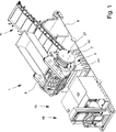
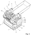
- the comminution device 1 has a drive device 4 at the end in the region of the comminution roller 2 for driving the comminution roller 2. Furthermore, a frame 5 is provided, which serves to hold and support the comminution roller 2 and the drive devices 4.
- the frame 5 is connected to a base plate 6, which are basically also frame-shaped can.
- the actual housing-like frame 5, which has side walls 7, 8, between which the comminution roller 2 is arranged, is placed on the base plate 6. Between the side walls 7, 8 there is a funnel 9 into which a chute 10 opens. The feed material that falls into the hopper 9 and is fed to the comminution roller 2 is added via the chute 10.
- the shredding device 1 in the in the Fig. 1 and 2nd Embodiments shown a conveyor 11, which is a belt conveyor in the present case.
- the conveyor 11 is adjustable via an inclination device.
- the feed end of the conveyor 11 is in the lower region of the frame 5 below the shredding roller 2, while the discharge end is guided away from the frame 5 and protrudes beyond the base plate 6 in length.
- the embodiment shown is not only missing on the base plate 6, but also on the conveyor 11.
- the frame 5 it is possible for the frame 5 to be mounted at one point on the substrate, in which case a shaft can be provided for the removal of the comminuted material to be comminuted.
- comminution tools 12 there are a plurality of comminution tools 12 distributed over the outer circumference of the comminution roller 2, while a counter comb 13 is provided in the frame 5 below the funnel 9.
- the comminution tools 12 mesh with the counter comb 13, which provides corresponding slots 14 for the individual comminution tools 12.
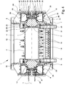
- the shredding roller 2 and the drive devices 4 provided at the end or end are each connected as a common assembly to a damping device 16, which in the present case is frictionally and elastically supported in or on the frame 5.
- each of the drive devices 4 has a gearless motor 17, so that an overall very compact and small-sized design of the comminution device 1 results, as can be seen in particular from FIGS Fig. 4 and 5 results.
- the motor 17 is a hydraulic motor in the form of a radial piston motor.
- the engine 17 is how this can be seen in particular from the Fig. 1 and 2nd results in a hydraulic pump device 18, which in the present case is driven by a diesel engine 19.
- the hydraulic pump device 18 is connected to the motor 17 via hydraulic hoses 20.
- the drive device 4 or the motor 17 is assigned a control device for controlling the speed of the motor 17 and thus the comminution roller 2, the control ultimately taking place in that the oil flow is controlled by the hydraulic pump device 18.
- the motors 17 are firmly connected to the shredding roller 2 and form a common assembly in the motor-shredding roller-motor arrangement.
- a connection flange 21 is fastened to the output side of the motors 17, in the present case screwed on.
- the motor housing already has a corresponding connection flange.
- the connecting flange 21 is in turn screwed to the comminuting roller 2, in the present case with an edge flange 22 of the comminuting roller 2.
- the connecting flange 21 ultimately serves as an adapter in order to adapt the comparatively small motor 17 to the comparatively larger comminuting roller 2.
- the fastening of the motors 17 on both sides of the comminution roller 2 does not differ from one another. Both motors 17 are thus attached to the face of the shredding roller 2 in the same way.
- corresponding openings 23, 24 provided.
- annular gap 25 between the outside of the motors 17 and the openings 23, 24.
- the shredding roller 2 including the motors 17 which are connected in a rotationally fixed manner to it, is mounted damped on both sides, namely via a damping device 16 provided on each side.
- the damping device 16 is designed on both sides in such a way that movement of the shredding roller 2 in the axial direction, that is in the direction of the axis of rotation 3 and in the radial direction, that is to say transversely to the axis of rotation 3.
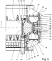
- Each of the damping devices 16 has an annular flexible damping means 26, which is arranged in a corresponding circular receptacle 27 in the present case in a frictional and / or form-fitting manner, but in any case in a torsionally rigid manner. This will be discussed in more detail below.
- the receptacle 27 is part of the frame 5 or fixed to the frame 5.
- the damping means 26 consists at least essentially, in particular on its peripheral outside, of a rubber material and has depressions 28 and projections 29.
- said projections 30 On the inside of the receptacle 27 facing the damping means 26, said projections 30 have engages in the depressions 28 and depressions 31 for engaging the projections 29, so that there is a positive fit via the corresponding depressions 28, 31 and projections 29, 30.
- the receptacle 27 consists of metal, in particular steel, so that a comparatively large coefficient of friction results due to the material pairing of the rubber of the damping means 26 and the steel surface.
- the damping means 26 consists of an elastic material.
- the damping agent 26 may have rubber as the base material, optionally with reinforcing material contained in the damping agent 26.
- the damping means 26 is a fillable hollow body. Compressed air is provided in the present case for filling the hollow body. Another printing medium can also be used.
- the damping means 26 is designed in the manner of a wheel tire which has an outer contact surface 32 to which side cheeks 33, 34 are connected laterally. The damping means 26 is opened on the inside, so that a U-shape results in the cross section. This will be dealt with below.
- the aforementioned design of the damping means 26 in the manner of a wheel tire makes it possible to fill the damping means 26 with compressed air even during the operation of the comminution device 1, in order to increase the pressure and thus the stiffness of the damping means 26 or, if necessary, to reduce it.
- a measuring device for measuring the pressure in the damping means 26 is provided for correct pressure setting and thus also corresponding to the setting of the rigidity.
- the measuring device has a sensor, not shown, which communicates with the interior of the hollow damping means 26. If necessary, the sensor can protrude into the interior of the damping means.
- the measuring device is coupled to a control device, which in turn is coupled to a signal device for optical and / or acoustic signal output, a switch-off device for the drive devices 4 and / or a filling device for filling and / or emptying the damping means 26.
- the damping means 26 is connected to the assembly resulting from the two drive devices 4 and the comminution roller 2 connected in a rotationally fixed manner via a connecting means 36.
- the connecting means 36 is a rim-like body with an inner flange plate 37, which is used for fastening / flange mounting the outside of the motor 17 is used.
- the connecting means 36 has a hollow cylindrical fastening region 38 on the outside, which is connected to the inside of the flange plate 37 and which is designed on its outside for connection to the damping means 26.
- the fastening area 38 has a circumferential projection 39, 40 on the edge against which the inner edges of the side cheeks 33, 34 bear on the inside and simultaneously seal at this point when the damping means 26 is filled with the pressure medium.
- the receptacle 27 is closed by a support plate 42 which is placed on the receptacle 27.
- recesses 43 are provided on the support plate 42, into which the associated reinforcement cheeks 41 engage with their end 44.
- the support plate 42 also has through openings 45, 46 for the passage of the hydraulic hoses 20 for the motor 17 and a pressure line 47, which is connected to a filling device for the damping means.
- this can be a pneumatic device for supplying compressed air to the damping device 16.
- a cylindrical stop body 48 On the inside of the support plate 42 there is a cylindrical stop body 48.
- a hollow cylindrical or cup-shaped section 49 is centrally attached to the flange plate 37.
- the central axis of section 49 is located on axis of rotation 3.
- the stop body 48 protrudes into the section 49, leaving a free space both on the end face and in the radial direction, which is smaller than the free spaces in the slots 14 between the shredding tools 12 and the counter-comb teeth 15. This ensures that the movement of the Assembly in the axial or radial direction does not lead to the comminution tools 12 coming into engagement with the counter comb teeth 15.
- a stop projection 50 can be provided on the inside of one or both side walls 7, 8, which projection points in the direction of the connecting flange 21.
- the free space remaining between the stop projection 50 and the connecting flange 21 is in turn less than the free spaces in the slots 14 between the counter comb 13 and the crushing tools 12 when these are moved by the counter comb 13.
- the comminution roller 2 rotates with a predetermined rotational speed at a predetermined speed, which can be adjusted via the motors 17, if necessary.
- the material to be crushed which is fed onto the chute 10 and falls into the hopper 9, is crushed by means of the crushing tools 12 in the area of the counter comb 13.
- the damping device 16 enables the structural unit consisting of the comminution roller 2 and the motors 17 to perform an evasive movement in the axial and / or radial direction with respect to the axis of rotation 3, to the extent that until the respective sling is effective.
- damping means 26 is arranged in the receptacle 27 in a torsionally rigid manner. It is particularly important to ensure that the stiffness of the damping means 26 is selected so that the projections 29, 30 and the depressions 28, 31 always engage in one another. The damping means 26 can then dampen the movements of the assembly occurring due to the elasticity of the material of the damping means 26 or its rigidity.
- Fig. 6 shows a fixing device 52 which is fixedly connected to the flange plate 37 and the connecting means 36.
- the fixing device 52 can be connected to the fastening area 38.
- the fixing device 52 fixes the connecting means 36, the damping means 26 and the damping device 16 on the receptacle 27 and accordingly indirectly on the frame 5, so that the damping device 16, the damping means 26 and the connecting means 36 are connected to the frame 5 in a torsionally rigid manner.
- a direct attachment of the fixing device 52 to the frame 5 is also possible.
- the fixing device 52 is designed in such a way that a torsionally rigid connection of the damping means 26 to the drive device 4 can be ensured even under very high loads.
- Fig. 9 shows that in the illustrated embodiment, the fixing device 52 has a fastening section 55 and an active section 56. From the in Fig. 9 shown cross-sectional view results that the fixing device 52 has an angular cross-sectional shape.
- the fastening section 55 is firmly connected to the connecting means 36 in the exemplary embodiment shown.
- the active section 56 is arranged at least indirectly on the frame 5.
- the Fig. 7 shows that the active section 56 interacts with the receptacle 27.
- the active section 56 is arranged and fastened to the support device 51, which is firmly connected to the frame 5.
- the support device 51 can be designed as part of the receptacle 27 and / or can be fastened to the frame 5 independently of the receptacle 27.
- the active section 56 of the fixing device 52 interacts directly or directly with the bearing wall 7, 8 of the frame 5.
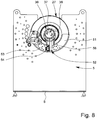
- Fig. 8 shows that the support device 51 surrounds the lower half, which faces the base plate 6, of the damping means 26 or the receptacle 27. Instead of a support plate 42, the damping means 26 or the connecting means 36 is closed at least in sections by the support device 51.
- a plurality of openings 53 are provided on the support device 51 - in other embodiments on the receptacle 27.
- the openings 53 serve for the arrangement or fastening of the fixing device 52 and are accordingly designed for the engagement of screws.
- the fixing device 52 in the exemplary embodiment shown has a connecting means 54 or a connecting means 54 is assigned to the fixing device 52.
- the connection means 54 likewise has openings and serves for the arrangement of screws and for fixing the active section 56 of the fixing device 52.
- FIG Fig. 7 A perspective view of the fixing device 52 is shown in FIG Fig. 7 shown. Furthermore, based on Fig. 7 it can be seen that the fixing device 52 can be arranged at different positions on the receptacle 27 or on the support device 51. In the exemplary embodiment shown, the fixing device 52 or the active section 56 is arranged at least substantially transversely or at a 90 ° angle to the cutting engagement - comminution tool 12 to counter comb tooth 15. The angle specifications relate to an apex which is related to the axis of rotation 3 of the comminution roller 2.
- the Fig. 8 illustrates that starting from this 90 ° position, the effective section 56 of the fixing device 52 can be adjusted in a range of +/- 45 ° to the 90 ° position shown in the exemplary embodiments shown.
- the arrangement of the fixing device 52 or of the active section 56 can vary in an embodiment, not shown, in an angular range from 0 ° to 360 ° 6 to 9 illustrated embodiments, the 90 ° position is shown.
- the fixing device 52 is arranged only on the lower half of the receptacle 27 or the connecting means 36.
- the fixing device 52 can be arranged in any area of the receptacle 27 or the connecting means 36.
- Fig. 10 shows a further embodiment of the fixing device 52, wherein a spherical contact surface is provided as a connection means 54 or on the active section 56.
- the fixing device 52 - in the out Fig. 10 apparent embodiment - serves to support the torque of the damping means 26.
- the connection means 54 acts as a stop, it is not important to the formation of the contact surface.
- the fixing device 52 can ultimately also be viewed as a counter-holder.
- the counterholder or the fixing device 52 which ultimately has the function of a claw or a clamping claw, is arranged on the frame 5 in a frame-fixed manner and is connected to the frame 5 in a torsionally rigid manner.
- the torsionally rigid connection of the fixing device 52 to the frame 5 is achieved via the torsionally rigid connection of the fastening section 55 to the connecting means 36 and the interaction between the active section 56 and the bearing wall 7, 8 of the frame 5.
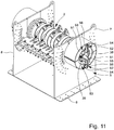
- the Fig. 10 and 11 It can be seen that two fixing devices 52 are arranged on the receptacle 27.
- the first, lower fixing device 52 is arranged in a 90 ° position with respect to the cutting engagement, the fixing devices 52 enclosing an angle of at least essentially 180 ° with one another and accordingly lying opposite one another.
- the Fig. 10 and 11 that two support devices 51 are arranged on the frame 5 or the bearing wall 7, 8 or are fixedly connected to the frame 5.
- the active sections 56 of the fixing devices 52 are arranged on the support devices 51 in the exemplary embodiment shown - in the specific exemplary embodiment they are connected to the support devices 51 in a torsionally rigid manner.
- the support devices 51 can be regarded as part of the receptacle 27 or, in further embodiments, as separate components.
- the second, upper fixing device 52 is at least substantially identical in construction to the first, lower fixing device 52.
- the first, lower fixing device 52 is at least substantially identical to the previously described embodiment, which is based on FIGS 6 to 9 can be seen trained. Consequently, additional, further explanations for avoiding repetitions can be dispensed with.
- both fixing devices 52 can be adjusted by arranging the connecting means 54 at other openings 53 of the respective support device 51 and connecting them to the support device 51 in a positive and / or non-positive manner by means of screws.
- the fixing devices 52 can enclose an angle between 80 ° to 180 °, in further embodiments between 140 ° to 180 °.
- the arrangement of the second fixing device 52 - as in FIGS Fig. 11 and 12th shown - can be changed by +/- 100 °.
- a plurality of fixing devices 52 can be connected to the connecting means 36 and arranged at least indirectly on the bearing wall 7, 8.
Landscapes
- Engineering & Computer Science (AREA)
- Food Science & Technology (AREA)
- Environmental & Geological Engineering (AREA)
- Crushing And Grinding (AREA)
- Crushing And Pulverization Processes (AREA)
- Processing Of Solid Wastes (AREA)
Priority Applications (2)
| Application Number | Priority Date | Filing Date | Title |
|---|---|---|---|
| PL18703892T PL3565669T3 (pl) | 2017-02-27 | 2018-01-19 | Urządzenie rozdrabniające do rozdrabniania przedmiotu rozdrabniania |
| SI201830091T SI3565669T1 (sl) | 2017-02-27 | 2018-01-19 | Drobilna naprava za drobljenje materiala za drobljenje |
Applications Claiming Priority (2)
| Application Number | Priority Date | Filing Date | Title |
|---|---|---|---|
| DE102017001813.8A DE102017001813B3 (de) | 2017-02-27 | 2017-02-27 | Zerkleinerungsvorrichtung zur Zerkleinerung von Zerkleinerungsgut |
| PCT/EP2018/000025 WO2018153541A1 (de) | 2017-02-27 | 2018-01-19 | Zerkleinerungsvorrichtung zur zerkleinerung von zerkleinerungsgut |
Publications (2)
| Publication Number | Publication Date |
|---|---|
| EP3565669A1 EP3565669A1 (de) | 2019-11-13 |
| EP3565669B1 true EP3565669B1 (de) | 2020-05-13 |
Family
ID=61188744
Family Applications (1)
| Application Number | Title | Priority Date | Filing Date |
|---|---|---|---|
| EP18703892.2A Active EP3565669B1 (de) | 2017-02-27 | 2018-01-19 | Zerkleinerungsvorrichtung zur zerkleinerung von zerkleinerungsgut |
Country Status (11)
| Country | Link |
|---|---|
| US (1) | US11298705B2 (pl) |
| EP (1) | EP3565669B1 (pl) |
| JP (1) | JP6957653B2 (pl) |
| KR (1) | KR102532354B1 (pl) |
| CA (1) | CA3053431C (pl) |
| DE (1) | DE102017001813B3 (pl) |
| ES (1) | ES2807239T3 (pl) |
| HU (1) | HUE050505T2 (pl) |
| PL (1) | PL3565669T3 (pl) |
| SI (1) | SI3565669T1 (pl) |
| WO (1) | WO2018153541A1 (pl) |
Families Citing this family (9)
| Publication number | Priority date | Publication date | Assignee | Title |
|---|---|---|---|---|
| CN110369099B (zh) * | 2019-07-31 | 2020-12-11 | 涡阳县沪涡多孔矸石砖有限公司 | 一种工业固体废弃物的造块方法 |
| CN111298937A (zh) * | 2019-12-30 | 2020-06-19 | 天津市铁柱纸制品工贸有限公司 | 一种无害化生物降解池 |
| CN113399436B (zh) * | 2021-07-02 | 2023-01-03 | 山东福土环境工程有限公司 | 固体废弃物处理系统 |
| CN114029313B (zh) * | 2021-11-02 | 2022-08-26 | 杭州燎发环保设备有限公司 | 一种花圈粉碎机 |
| CN114985078A (zh) * | 2022-05-26 | 2022-09-02 | 黄河水利职业技术学院 | 一种绿色的建筑垃圾回收设备 |
| DE102022001978B4 (de) | 2022-06-08 | 2026-03-05 | ALLRECO GmbH | Drehvorrichtung |
| CN115156235A (zh) * | 2022-07-05 | 2022-10-11 | 合肥综合性国家科学中心能源研究院(安徽省能源实验室) | 一种具有均匀布料功能的煤基固废灌注用粉碎装置 |
| CN115138458B (zh) * | 2022-07-28 | 2024-03-12 | 海赢印务科技(南通)有限公司 | 一种数字印刷机纸料粉碎机构 |
| CN117656305A (zh) * | 2023-11-30 | 2024-03-08 | 安徽富乐德科技发展股份有限公司 | 银色残膜清洗工艺装备 |
Family Cites Families (16)
| Publication number | Priority date | Publication date | Assignee | Title |
|---|---|---|---|---|
| US2832280A (en) | 1956-03-02 | 1958-04-29 | Farrel Birmingham Co Inc | Floating journal boxes for crushing mills |
| FR1589720A (pl) * | 1968-09-05 | 1970-04-06 | ||
| DE8604024U1 (de) * | 1986-02-14 | 1986-03-27 | Krupp Polysius Ag, 4720 Beckum | Gutbett-Walzenmühle |
| DE4110643A1 (de) * | 1991-04-02 | 1992-10-08 | Krupp Polysius Ag | Walzenmuehle |
| US6285525B1 (en) * | 1998-07-01 | 2001-09-04 | 3M Innovative Properties Company | Damped spacer articles and disk drive assemblies containing damped spacer articles |
| KR200241966Y1 (ko) * | 2000-12-28 | 2001-09-25 | 김경영 | 파쇄기의 자동 유압 조절 장치가 부착된 유압 시스템 |
| JP2003093910A (ja) * | 2001-09-25 | 2003-04-02 | Niigata Prefecture | 破砕機の安全装置 |
| DE102005062963A1 (de) | 2005-12-28 | 2007-07-12 | Vecoplan Maschinenfabrik Gmbh & Co. Kg | Zerkleinerungsvorrichtung mit reduzierter Lagerzahl |
| DE102009000442B4 (de) * | 2009-01-27 | 2011-04-07 | Neuman & Esser Gmbh Mahl- Und Sichtsysteme | Getriebelose Pendelmühle |
| JP2011020039A (ja) * | 2009-07-15 | 2011-02-03 | Masami Kawana | 廃コンクリート破砕装置 |
| EP2545994A1 (de) | 2011-07-15 | 2013-01-16 | ABB Technology AG | Anordnung für eine Walzenmühle |
| DE102011052633B3 (de) * | 2011-08-12 | 2012-09-13 | Thyssenkrupp Polysius Ag | Walzenbrecher mit Drehmomentstütze |
| CN202527212U (zh) * | 2012-04-12 | 2012-11-14 | 宋晓烨 | 辊压式粉碎机 |
| WO2013167497A2 (de) * | 2012-05-07 | 2013-11-14 | Erdmann Gmbh & Co. Kg | Zerkleinerungsmaschine |
| FI128209B (fi) * | 2013-06-14 | 2019-12-31 | Metso Minerals Inc | Menetelmä ja järjestelmä mineraalimateriaalin murskaimen rungon kannattelemiseksi murskauslaitoksen rungolla sekä mineraalimateriaalin prosessointilaitos |
| DE102013219629A1 (de) | 2013-09-27 | 2015-04-02 | Siemens Aktiengesellschaft | Aufbereitungsmaschine und Aufbereitungsanlage |
-
2017
- 2017-02-27 DE DE102017001813.8A patent/DE102017001813B3/de active Active
-
2018
- 2018-01-19 ES ES18703892T patent/ES2807239T3/es active Active
- 2018-01-19 JP JP2019567776A patent/JP6957653B2/ja active Active
- 2018-01-19 US US16/483,108 patent/US11298705B2/en active Active
- 2018-01-19 EP EP18703892.2A patent/EP3565669B1/de active Active
- 2018-01-19 KR KR1020197025465A patent/KR102532354B1/ko active Active
- 2018-01-19 SI SI201830091T patent/SI3565669T1/sl unknown
- 2018-01-19 PL PL18703892T patent/PL3565669T3/pl unknown
- 2018-01-19 CA CA3053431A patent/CA3053431C/en active Active
- 2018-01-19 WO PCT/EP2018/000025 patent/WO2018153541A1/de not_active Ceased
- 2018-01-19 HU HUE18703892A patent/HUE050505T2/hu unknown
Non-Patent Citations (1)
| Title |
|---|
| None * |
Also Published As
| Publication number | Publication date |
|---|---|
| BR112019017399A2 (pt) | 2020-03-31 |
| CA3053431C (en) | 2022-03-29 |
| CA3053431A1 (en) | 2018-08-30 |
| KR20190117572A (ko) | 2019-10-16 |
| KR102532354B1 (ko) | 2023-05-15 |
| ES2807239T3 (es) | 2021-02-22 |
| WO2018153541A1 (de) | 2018-08-30 |
| JP6957653B2 (ja) | 2021-11-02 |
| US20200023375A1 (en) | 2020-01-23 |
| PL3565669T3 (pl) | 2020-11-16 |
| JP2020510532A (ja) | 2020-04-09 |
| US11298705B2 (en) | 2022-04-12 |
| DE102017001813B3 (de) | 2018-07-12 |
| HUE050505T2 (hu) | 2020-12-28 |
| EP3565669A1 (de) | 2019-11-13 |
| SI3565669T1 (sl) | 2020-09-30 |
Similar Documents
| Publication | Publication Date | Title |
|---|---|---|
| EP3565669B1 (de) | Zerkleinerungsvorrichtung zur zerkleinerung von zerkleinerungsgut | |
| DE102008039542B4 (de) | Rollenmühle | |
| EP3597300B1 (de) | Walzenpakete für vermahlungsvorrichtungen, vermahlungsvorrichtungen und verfahren | |
| EP2846918A2 (de) | Zerkleinerungsmaschine | |
| DE102012216914A1 (de) | Zerkleinerungsvorrichtung | |
| DE102009060523A1 (de) | Zerkleinerungsvorrichtung mit Gegenmessereinrichtung | |
| DE102012009987A1 (de) | Laborkugelmühle | |
| EP1731223B1 (de) | Zerkleinerungsvorrichtung | |
| EP3831494B1 (de) | Schneidmühle zum schneidenden zerkleinern von proben | |
| EP2883612A1 (de) | Walzenmühle und Anordnung zum Antrieb einer Walzenmühle | |
| EP1960108A1 (de) | Rotor für eine prallmühle | |
| DE102022001978B4 (de) | Drehvorrichtung | |
| WO2008012096A2 (de) | Kraftübertragungseinrichtung für eine zerkleinerungsvorrichtung | |
| EP3488971A1 (de) | Elektrisch antreibbare schwenkvorrichtung | |
| EP2374544A2 (de) | Vorrichtung zum Zerkleinern von kompostierbarem Material | |
| EP2536555B1 (de) | Pelletpresse | |
| AT523406B1 (de) | Zerkleinerungsmaschine | |
| DE29616319U1 (de) | Walzenbrecher | |
| DE102017011922B4 (de) | Zerkleinerungsvorrichtung zur Zerkleinerung von Zerkleinerungsgut | |
| EP3981515B1 (de) | Zerkleinerungsvorrichtung zur zerkleinerung von zerkleinerungsgut | |
| DE202011107220U1 (de) | Drahtfördervorrichtung | |
| DE102011000749A1 (de) | Walzenmühle | |
| EP2282837B1 (de) | Rollenmühle | |
| WO2012089291A2 (de) | Zerkleinerungsmaschine | |
| DE102022126952B3 (de) | Bodenrecycler mit einem Schaufelgehäuse |
Legal Events
| Date | Code | Title | Description |
|---|---|---|---|
| STAA | Information on the status of an ep patent application or granted ep patent |
Free format text: STATUS: UNKNOWN |
|
| STAA | Information on the status of an ep patent application or granted ep patent |
Free format text: STATUS: THE INTERNATIONAL PUBLICATION HAS BEEN MADE |
|
| PUAI | Public reference made under article 153(3) epc to a published international application that has entered the european phase |
Free format text: ORIGINAL CODE: 0009012 |
|
| STAA | Information on the status of an ep patent application or granted ep patent |
Free format text: STATUS: REQUEST FOR EXAMINATION WAS MADE |
|
| 17P | Request for examination filed |
Effective date: 20190705 |
|
| AK | Designated contracting states |
Kind code of ref document: A1 Designated state(s): AL AT BE BG CH CY CZ DE DK EE ES FI FR GB GR HR HU IE IS IT LI LT LU LV MC MK MT NL NO PL PT RO RS SE SI SK SM TR |
|
| AX | Request for extension of the european patent |
Extension state: BA ME |
|
| STAA | Information on the status of an ep patent application or granted ep patent |
Free format text: STATUS: EXAMINATION IS IN PROGRESS |
|
| 17Q | First examination report despatched |
Effective date: 20200107 |
|
| GRAP | Despatch of communication of intention to grant a patent |
Free format text: ORIGINAL CODE: EPIDOSNIGR1 |
|
| STAA | Information on the status of an ep patent application or granted ep patent |
Free format text: STATUS: GRANT OF PATENT IS INTENDED |
|
| RAP1 | Party data changed (applicant data changed or rights of an application transferred) |
Owner name: LIG GMBH |
|
| DAV | Request for validation of the european patent (deleted) | ||
| DAX | Request for extension of the european patent (deleted) | ||
| INTG | Intention to grant announced |
Effective date: 20200217 |
|
| GRAS | Grant fee paid |
Free format text: ORIGINAL CODE: EPIDOSNIGR3 |
|
| GRAA | (expected) grant |
Free format text: ORIGINAL CODE: 0009210 |
|
| STAA | Information on the status of an ep patent application or granted ep patent |
Free format text: STATUS: THE PATENT HAS BEEN GRANTED |
|
| AK | Designated contracting states |
Kind code of ref document: B1 Designated state(s): AL AT BE BG CH CY CZ DE DK EE ES FI FR GB GR HR HU IE IS IT LI LT LU LV MC MK MT NL NO PL PT RO RS SE SI SK SM TR |
|
| REG | Reference to a national code |
Ref country code: GB Ref legal event code: FG4D Free format text: NOT ENGLISH |
|
| REG | Reference to a national code |
Ref country code: CH Ref legal event code: EP |
|
| REG | Reference to a national code |
Ref country code: DE Ref legal event code: R096 Ref document number: 502018001445 Country of ref document: DE |
|
| REG | Reference to a national code |
Ref country code: AT Ref legal event code: REF Ref document number: 1269545 Country of ref document: AT Kind code of ref document: T Effective date: 20200615 |
|
| REG | Reference to a national code |
Ref country code: NL Ref legal event code: FP |
|
| REG | Reference to a national code |
Ref country code: FI Ref legal event code: FGE |
|
| REG | Reference to a national code |
Ref country code: SE Ref legal event code: TRGR |
|
| REG | Reference to a national code |
Ref country code: NO Ref legal event code: T2 Effective date: 20200513 |
|
| REG | Reference to a national code |
Ref country code: SK Ref legal event code: T3 Ref document number: E 34639 Country of ref document: SK |
|
| REG | Reference to a national code |
Ref country code: LT Ref legal event code: MG4D |
|
| PG25 | Lapsed in a contracting state [announced via postgrant information from national office to epo] |
Ref country code: PT Free format text: LAPSE BECAUSE OF FAILURE TO SUBMIT A TRANSLATION OF THE DESCRIPTION OR TO PAY THE FEE WITHIN THE PRESCRIBED TIME-LIMIT Effective date: 20200914 Ref country code: IS Free format text: LAPSE BECAUSE OF FAILURE TO SUBMIT A TRANSLATION OF THE DESCRIPTION OR TO PAY THE FEE WITHIN THE PRESCRIBED TIME-LIMIT Effective date: 20200913 Ref country code: LT Free format text: LAPSE BECAUSE OF FAILURE TO SUBMIT A TRANSLATION OF THE DESCRIPTION OR TO PAY THE FEE WITHIN THE PRESCRIBED TIME-LIMIT Effective date: 20200513 Ref country code: GR Free format text: LAPSE BECAUSE OF FAILURE TO SUBMIT A TRANSLATION OF THE DESCRIPTION OR TO PAY THE FEE WITHIN THE PRESCRIBED TIME-LIMIT Effective date: 20200814 |
|
| PG25 | Lapsed in a contracting state [announced via postgrant information from national office to epo] |
Ref country code: BG Free format text: LAPSE BECAUSE OF FAILURE TO SUBMIT A TRANSLATION OF THE DESCRIPTION OR TO PAY THE FEE WITHIN THE PRESCRIBED TIME-LIMIT Effective date: 20200813 Ref country code: RS Free format text: LAPSE BECAUSE OF FAILURE TO SUBMIT A TRANSLATION OF THE DESCRIPTION OR TO PAY THE FEE WITHIN THE PRESCRIBED TIME-LIMIT Effective date: 20200513 Ref country code: HR Free format text: LAPSE BECAUSE OF FAILURE TO SUBMIT A TRANSLATION OF THE DESCRIPTION OR TO PAY THE FEE WITHIN THE PRESCRIBED TIME-LIMIT Effective date: 20200513 Ref country code: LV Free format text: LAPSE BECAUSE OF FAILURE TO SUBMIT A TRANSLATION OF THE DESCRIPTION OR TO PAY THE FEE WITHIN THE PRESCRIBED TIME-LIMIT Effective date: 20200513 |
|
| REG | Reference to a national code |
Ref country code: HU Ref legal event code: AG4A Ref document number: E050505 Country of ref document: HU |
|
| PG25 | Lapsed in a contracting state [announced via postgrant information from national office to epo] |
Ref country code: AL Free format text: LAPSE BECAUSE OF FAILURE TO SUBMIT A TRANSLATION OF THE DESCRIPTION OR TO PAY THE FEE WITHIN THE PRESCRIBED TIME-LIMIT Effective date: 20200513 |
|
| PG25 | Lapsed in a contracting state [announced via postgrant information from national office to epo] |
Ref country code: SM Free format text: LAPSE BECAUSE OF FAILURE TO SUBMIT A TRANSLATION OF THE DESCRIPTION OR TO PAY THE FEE WITHIN THE PRESCRIBED TIME-LIMIT Effective date: 20200513 Ref country code: EE Free format text: LAPSE BECAUSE OF FAILURE TO SUBMIT A TRANSLATION OF THE DESCRIPTION OR TO PAY THE FEE WITHIN THE PRESCRIBED TIME-LIMIT Effective date: 20200513 Ref country code: DK Free format text: LAPSE BECAUSE OF FAILURE TO SUBMIT A TRANSLATION OF THE DESCRIPTION OR TO PAY THE FEE WITHIN THE PRESCRIBED TIME-LIMIT Effective date: 20200513 Ref country code: RO Free format text: LAPSE BECAUSE OF FAILURE TO SUBMIT A TRANSLATION OF THE DESCRIPTION OR TO PAY THE FEE WITHIN THE PRESCRIBED TIME-LIMIT Effective date: 20200513 |
|
| REG | Reference to a national code |
Ref country code: DE Ref legal event code: R097 Ref document number: 502018001445 Country of ref document: DE |
|
| REG | Reference to a national code |
Ref country code: ES Ref legal event code: FG2A Ref document number: 2807239 Country of ref document: ES Kind code of ref document: T3 Effective date: 20210222 |
|
| PLBE | No opposition filed within time limit |
Free format text: ORIGINAL CODE: 0009261 |
|
| STAA | Information on the status of an ep patent application or granted ep patent |
Free format text: STATUS: NO OPPOSITION FILED WITHIN TIME LIMIT |
|
| 26N | No opposition filed |
Effective date: 20210216 |
|
| REG | Reference to a national code |
Ref country code: DE Ref legal event code: R081 Ref document number: 502018001445 Country of ref document: DE Owner name: DOPPSTADT BETEILIGUNGS GMBH, DE Free format text: FORMER OWNER: LIG GMBH, 42555 VELBERT, DE Ref country code: DE Ref legal event code: R081 Ref document number: 502018001445 Country of ref document: DE Owner name: LIG GMBH, DE Free format text: FORMER OWNER: LIG GMBH, 42555 VELBERT, DE |
|
| PG25 | Lapsed in a contracting state [announced via postgrant information from national office to epo] |
Ref country code: MC Free format text: LAPSE BECAUSE OF FAILURE TO SUBMIT A TRANSLATION OF THE DESCRIPTION OR TO PAY THE FEE WITHIN THE PRESCRIBED TIME-LIMIT Effective date: 20200513 |
|
| REG | Reference to a national code |
Ref country code: CH Ref legal event code: PL |
|
| PG25 | Lapsed in a contracting state [announced via postgrant information from national office to epo] |
Ref country code: LU Free format text: LAPSE BECAUSE OF NON-PAYMENT OF DUE FEES Effective date: 20210119 |
|
| REG | Reference to a national code |
Ref country code: BE Ref legal event code: MM Effective date: 20210131 |
|
| PG25 | Lapsed in a contracting state [announced via postgrant information from national office to epo] |
Ref country code: LI Free format text: LAPSE BECAUSE OF NON-PAYMENT OF DUE FEES Effective date: 20210131 Ref country code: CH Free format text: LAPSE BECAUSE OF NON-PAYMENT OF DUE FEES Effective date: 20210131 |
|
| PG25 | Lapsed in a contracting state [announced via postgrant information from national office to epo] |
Ref country code: IE Free format text: LAPSE BECAUSE OF NON-PAYMENT OF DUE FEES Effective date: 20210119 |
|
| PG25 | Lapsed in a contracting state [announced via postgrant information from national office to epo] |
Ref country code: BE Free format text: LAPSE BECAUSE OF NON-PAYMENT OF DUE FEES Effective date: 20210131 |
|
| REG | Reference to a national code |
Ref country code: DE Ref legal event code: R081 Ref document number: 502018001445 Country of ref document: DE Owner name: DOPPSTADT BETEILIGUNGS GMBH, DE Free format text: FORMER OWNER: LIG GMBH, 42551 VELBERT, DE |
|
| PG25 | Lapsed in a contracting state [announced via postgrant information from national office to epo] |
Ref country code: CY Free format text: LAPSE BECAUSE OF FAILURE TO SUBMIT A TRANSLATION OF THE DESCRIPTION OR TO PAY THE FEE WITHIN THE PRESCRIBED TIME-LIMIT Effective date: 20200513 |
|
| P01 | Opt-out of the competence of the unified patent court (upc) registered |
Effective date: 20230613 |
|
| PG25 | Lapsed in a contracting state [announced via postgrant information from national office to epo] |
Ref country code: MK Free format text: LAPSE BECAUSE OF FAILURE TO SUBMIT A TRANSLATION OF THE DESCRIPTION OR TO PAY THE FEE WITHIN THE PRESCRIBED TIME-LIMIT Effective date: 20200513 |
|
| PG25 | Lapsed in a contracting state [announced via postgrant information from national office to epo] |
Ref country code: MT Free format text: LAPSE BECAUSE OF FAILURE TO SUBMIT A TRANSLATION OF THE DESCRIPTION OR TO PAY THE FEE WITHIN THE PRESCRIBED TIME-LIMIT Effective date: 20200513 |
|
| PGFP | Annual fee paid to national office [announced via postgrant information from national office to epo] |
Ref country code: SI Payment date: 20250109 Year of fee payment: 8 |
|
| PGFP | Annual fee paid to national office [announced via postgrant information from national office to epo] |
Ref country code: PL Payment date: 20250113 Year of fee payment: 8 Ref country code: CZ Payment date: 20250110 Year of fee payment: 8 |
|
| PGFP | Annual fee paid to national office [announced via postgrant information from national office to epo] |
Ref country code: SK Payment date: 20250114 Year of fee payment: 8 |
|
| PGFP | Annual fee paid to national office [announced via postgrant information from national office to epo] |
Ref country code: NL Payment date: 20260121 Year of fee payment: 9 |
|
| PGFP | Annual fee paid to national office [announced via postgrant information from national office to epo] |
Ref country code: HU Payment date: 20260123 Year of fee payment: 9 |
|
| PGFP | Annual fee paid to national office [announced via postgrant information from national office to epo] |
Ref country code: SE Payment date: 20260121 Year of fee payment: 9 |
|
| PGFP | Annual fee paid to national office [announced via postgrant information from national office to epo] |
Ref country code: GB Payment date: 20260123 Year of fee payment: 9 |
|
| PGFP | Annual fee paid to national office [announced via postgrant information from national office to epo] |
Ref country code: ES Payment date: 20260227 Year of fee payment: 9 |
|
| PGFP | Annual fee paid to national office [announced via postgrant information from national office to epo] |
Ref country code: DE Payment date: 20260120 Year of fee payment: 9 Ref country code: NO Payment date: 20260123 Year of fee payment: 9 |
|
| PGFP | Annual fee paid to national office [announced via postgrant information from national office to epo] |
Ref country code: AT Payment date: 20260122 Year of fee payment: 9 |
|
| PGFP | Annual fee paid to national office [announced via postgrant information from national office to epo] |
Ref country code: FI Payment date: 20260129 Year of fee payment: 9 Ref country code: IT Payment date: 20260126 Year of fee payment: 9 |
|
| PGFP | Annual fee paid to national office [announced via postgrant information from national office to epo] |
Ref country code: FR Payment date: 20260123 Year of fee payment: 9 |
|
| PGFP | Annual fee paid to national office [announced via postgrant information from national office to epo] |
Ref country code: TR Payment date: 20260115 Year of fee payment: 9 |