EP3564608B1 - Rahmenmontierte kühlbox, bauteile dafür und montageverfahren dafür - Google Patents
Rahmenmontierte kühlbox, bauteile dafür und montageverfahren dafür Download PDFInfo
- Publication number
- EP3564608B1 EP3564608B1 EP16925282.2A EP16925282A EP3564608B1 EP 3564608 B1 EP3564608 B1 EP 3564608B1 EP 16925282 A EP16925282 A EP 16925282A EP 3564608 B1 EP3564608 B1 EP 3564608B1
- Authority
- EP
- European Patent Office
- Prior art keywords
- panel
- ring
- bolts
- prefabricated
- beams
- Prior art date
- Legal status (The legal status is an assumption and is not a legal conclusion. Google has not performed a legal analysis and makes no representation as to the accuracy of the status listed.)
- Active
Links
Images



Classifications
-
- F—MECHANICAL ENGINEERING; LIGHTING; HEATING; WEAPONS; BLASTING
- F25—REFRIGERATION OR COOLING; COMBINED HEATING AND REFRIGERATION SYSTEMS; HEAT PUMP SYSTEMS; MANUFACTURE OR STORAGE OF ICE; LIQUEFACTION SOLIDIFICATION OF GASES
- F25J—LIQUEFACTION, SOLIDIFICATION OR SEPARATION OF GASES OR GASEOUS OR LIQUEFIED GASEOUS MIXTURES BY PRESSURE AND COLD TREATMENT OR BY BRINGING THEM INTO THE SUPERCRITICAL STATE
- F25J3/00—Processes or apparatus for separating the constituents of gaseous or liquefied gaseous mixtures involving the use of liquefaction or solidification
- F25J3/02—Processes or apparatus for separating the constituents of gaseous or liquefied gaseous mixtures involving the use of liquefaction or solidification by rectification, i.e. by continuous interchange of heat and material between a vapour stream and a liquid stream
- F25J3/04—Processes or apparatus for separating the constituents of gaseous or liquefied gaseous mixtures involving the use of liquefaction or solidification by rectification, i.e. by continuous interchange of heat and material between a vapour stream and a liquid stream for air
- F25J3/04763—Start-up or control of the process; Details of the apparatus used
- F25J3/04866—Construction and layout of air fractionation equipments, e.g. valves, machines
- F25J3/04945—Details of internal structure; insulation and housing of the cold box
-
- B—PERFORMING OPERATIONS; TRANSPORTING
- B65—CONVEYING; PACKING; STORING; HANDLING THIN OR FILAMENTARY MATERIAL
- B65D—CONTAINERS FOR STORAGE OR TRANSPORT OF ARTICLES OR MATERIALS, e.g. BAGS, BARRELS, BOTTLES, BOXES, CANS, CARTONS, CRATES, DRUMS, JARS, TANKS, HOPPERS, FORWARDING CONTAINERS; ACCESSORIES, CLOSURES, OR FITTINGS THEREFOR; PACKAGING ELEMENTS; PACKAGES
- B65D71/00—Bundles of articles held together by packaging elements for convenience of storage or transport, e.g. portable segregating carrier for plural receptacles such as beer cans or pop bottles; Bales of material
- B65D71/0088—Palletisable loads, i.e. loads intended to be transported by means of a fork-lift truck
- B65D71/0092—Palletisable loads, i.e. loads intended to be transported by means of a fork-lift truck provided with one or more rigid supports, at least one dimension of the supports corresponding to a dimension of the load, e.g. skids
-
- B—PERFORMING OPERATIONS; TRANSPORTING
- B65—CONVEYING; PACKING; STORING; HANDLING THIN OR FILAMENTARY MATERIAL
- B65D—CONTAINERS FOR STORAGE OR TRANSPORT OF ARTICLES OR MATERIALS, e.g. BAGS, BARRELS, BOTTLES, BOXES, CANS, CARTONS, CRATES, DRUMS, JARS, TANKS, HOPPERS, FORWARDING CONTAINERS; ACCESSORIES, CLOSURES, OR FITTINGS THEREFOR; PACKAGING ELEMENTS; PACKAGES
- B65D90/00—Component parts, details or accessories for large containers
- B65D90/12—Supports
- B65D90/16—Skids
-
- E—FIXED CONSTRUCTIONS
- E04—BUILDING
- E04B—GENERAL BUILDING CONSTRUCTIONS; WALLS, e.g. PARTITIONS; ROOFS; FLOORS; CEILINGS; INSULATION OR OTHER PROTECTION OF BUILDINGS
- E04B1/00—Constructions in general; Structures which are not restricted either to walls, e.g. partitions, or floors or ceilings or roofs
- E04B1/348—Structures composed of units comprising at least considerable parts of two sides of a room, e.g. box-like or cell-like units closed or in skeleton form
- E04B1/34815—Elements not integrated in a skeleton
- E04B1/3483—Elements not integrated in a skeleton the supporting structure consisting of metal
-
- E—FIXED CONSTRUCTIONS
- E04—BUILDING
- E04C—STRUCTURAL ELEMENTS; BUILDING MATERIALS
- E04C3/00—Structural elongated elements designed for load-supporting
- E04C3/30—Columns; Pillars; Struts
- E04C3/32—Columns; Pillars; Struts of metal
-
- E—FIXED CONSTRUCTIONS
- E04—BUILDING
- E04H—BUILDINGS OR LIKE STRUCTURES FOR PARTICULAR PURPOSES; SWIMMING OR SPLASH BATHS OR POOLS; MASTS; FENCING; TENTS OR CANOPIES, IN GENERAL
- E04H5/00—Buildings or groups of buildings for industrial or agricultural purposes
- E04H5/10—Buildings forming part of cooling plants
-
- E—FIXED CONSTRUCTIONS
- E04—BUILDING
- E04H—BUILDINGS OR LIKE STRUCTURES FOR PARTICULAR PURPOSES; SWIMMING OR SPLASH BATHS OR POOLS; MASTS; FENCING; TENTS OR CANOPIES, IN GENERAL
- E04H5/00—Buildings or groups of buildings for industrial or agricultural purposes
- E04H5/10—Buildings forming part of cooling plants
- E04H5/12—Cooling towers
-
- F—MECHANICAL ENGINEERING; LIGHTING; HEATING; WEAPONS; BLASTING
- F25—REFRIGERATION OR COOLING; COMBINED HEATING AND REFRIGERATION SYSTEMS; HEAT PUMP SYSTEMS; MANUFACTURE OR STORAGE OF ICE; LIQUEFACTION SOLIDIFICATION OF GASES
- F25J—LIQUEFACTION, SOLIDIFICATION OR SEPARATION OF GASES OR GASEOUS OR LIQUEFIED GASEOUS MIXTURES BY PRESSURE AND COLD TREATMENT OR BY BRINGING THEM INTO THE SUPERCRITICAL STATE
- F25J3/00—Processes or apparatus for separating the constituents of gaseous or liquefied gaseous mixtures involving the use of liquefaction or solidification
- F25J3/02—Processes or apparatus for separating the constituents of gaseous or liquefied gaseous mixtures involving the use of liquefaction or solidification by rectification, i.e. by continuous interchange of heat and material between a vapour stream and a liquid stream
- F25J3/0295—Start-up or control of the process; Details of the apparatus used, e.g. sieve plates, packings
-
- E—FIXED CONSTRUCTIONS
- E04—BUILDING
- E04B—GENERAL BUILDING CONSTRUCTIONS; WALLS, e.g. PARTITIONS; ROOFS; FLOORS; CEILINGS; INSULATION OR OTHER PROTECTION OF BUILDINGS
- E04B1/00—Constructions in general; Structures which are not restricted either to walls, e.g. partitions, or floors or ceilings or roofs
- E04B1/343—Structures characterised by movable, separable, or collapsible parts, e.g. for transport
- E04B1/34315—Structures characterised by movable, separable, or collapsible parts, e.g. for transport characterised by separable parts
-
- E—FIXED CONSTRUCTIONS
- E04—BUILDING
- E04B—GENERAL BUILDING CONSTRUCTIONS; WALLS, e.g. PARTITIONS; ROOFS; FLOORS; CEILINGS; INSULATION OR OTHER PROTECTION OF BUILDINGS
- E04B1/00—Constructions in general; Structures which are not restricted either to walls, e.g. partitions, or floors or ceilings or roofs
- E04B1/18—Structures comprising elongated load-supporting parts, e.g. columns, girders, skeletons
- E04B1/24—Structures comprising elongated load-supporting parts, e.g. columns, girders, skeletons the supporting parts consisting of metal
- E04B1/2403—Connection details of the elongated load-supporting parts
- E04B2001/2418—Details of bolting
-
- F—MECHANICAL ENGINEERING; LIGHTING; HEATING; WEAPONS; BLASTING
- F25—REFRIGERATION OR COOLING; COMBINED HEATING AND REFRIGERATION SYSTEMS; HEAT PUMP SYSTEMS; MANUFACTURE OR STORAGE OF ICE; LIQUEFACTION SOLIDIFICATION OF GASES
- F25J—LIQUEFACTION, SOLIDIFICATION OR SEPARATION OF GASES OR GASEOUS OR LIQUEFIED GASEOUS MIXTURES BY PRESSURE AND COLD TREATMENT OR BY BRINGING THEM INTO THE SUPERCRITICAL STATE
- F25J2290/00—Other details not covered by groups F25J2200/00 - F25J2280/00
- F25J2290/42—Modularity, pre-fabrication of modules, assembling and erection, horizontal layout, i.e. plot plan, and vertical arrangement of parts of the cryogenic unit, e.g. of the cold box
Definitions
- the present invention relates to a cold box assembly technology, and particularly to a skid-mounted cold box and its prefabricated assembly members and assembly method.
- a cold box is a core device of an air separation plant. It includes a thermally insulated box, where a tower and pipes and valves connecting the tower are set.
- cold boxes are divided into skid-mounted cold boxes and field-assembled cold boxes.
- For field-assembled cold boxes parts need to be assembled on site. The workload is heavy, and the assembly quality is easily affected by the construction environment.
- For skid-mounted cold boxes most assembly work is completed in a factory workshop where the environment is controlled. The product quality can be guaranteed, and the assembly cycle can be shortened.
- the two types of cold boxes are designed using the same material or similar materials and the same specification.
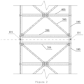
- a cold box includes a steel structural framework that is composed of parts such as a column 100, a beam 200, an oblique support 300 and an inter-beam support 400, as well as panels that cover all sides of the steel structural framework and enclose the box.
- a crane is mobilized to lift the upper prefabricated structure to the specified location so that it can be interconnected with the lower prefabricated structure.
- Full penetration welding is adopted for joining nodes 101 of the upper and lower columns 100 and nondestructive testing is performed for the welding seams to ensure that the joined columns 100 can vertically run through the cold box and transfer the shear force and bending moment generated by the upper part of the cold box.
- a second panel is connected to the column 100 and the beam 200 near the location where the prefabricated structures are joined, and seal welding is adopted for the joint node of the second panel. After all welding work is complete on site, the crane is dismissed.
- the present invention provides a skid-mounted cold box and its prefabricated assembly members and assembly method, aiming to reduce field assembly work as much as possible while not affecting the connection strength and airtightness of the cold box, so as to save field construction time and cost.
- a technical solution of the present invention provides assembly members to be joined to form a skid-mounted cold box according to Claim 1.
- the vertical section of the ring beam of each first and second prefabricated structure is I-shaped and has a vertical beam, a joining surface and a non-joining surface and the joining surface and the non-joining surface are fixed on the vertical beam and are parallel to each other; and the vertical section of the frame structure of each first and second prefabricated structure is L-shaped and has a first surface and a second surface that are perpendicular to each other.
- the first surface is connected to the inner side of edges of the first panel of the respective prefabricated structure and mounting holes for bolts are set at the joint so that the second panel can be fixed on the outer side of the first panel through the bolts; and the second surface is connected to the non-joining surface of the ring beam and extends towards the inner side of the framework.
- a connecting plate is set on the outer side of a location corresponding to a column on the ring beam.
- the connecting plate extends from the joining surface of the ring beam to the non-joining surface so that the assembled second panel can cover the connecting plate of the ring beam that is joined.
- mounting holes are set for a first bolt and a second bolt on the joining surface of the ring beam of each prefabricated structure, where the mounting hole for the first bolt is in a location corresponding to a column on the joining surface of the ring beam and the mounting hole for the second bolt is in another location on the joining surface of the ring beam; and the spacing of the mounting holes for the first bolt is smaller than the spacing of the mounting holes for the second bolt.
- the framework further includes:
- Another technical solution of the present invention provides a skid-mounted cold box according to Claim 6.
- the vertical section of the ring beam is I-shaped and has a vertical beam, a joining surface and a non-joining surface, where the joining surface and the non-joining surface are fixed on the vertical beam and are parallel to each other;
- the vertical section of the frame structure is L-shaped and has a first surface and a second surface that are perpendicular to each other.
- the first surface is connected to the inner side of edges of the first panel and mounting holes for bolts are set at the joint so that the second panel can be fixed on the outer side of the first panel through the bolts.
- the second surface is connected to the non-joining surface of the ring beam and extends towards the inner side of the framework.
- a connecting plate is set on the outer side of the location corresponding to a column on each ring beam.
- the connecting plate extends from the joining surface of the ring beam to the non-joining surface so that the assembled second panel can cover the outer side of the connecting plates for the two prefabricated structures that are joined.
- a washer made of neoprene is set between the second panel and the first panel.
- bolts connecting ring beams in two adjacent prefabricated structures are friction-type high-strength bolts; and the spacing of the bolt in a location corresponding to a column on the joining surface of any ring beam is smaller than the spacing of bolts in other locations on the joining surface of the ring beam.
- any one prefabricated structure further includes:
- the skid-mounted cold box according to the present invention provides a method according to Claim 9 [0038]
- the present invention can cancel all field welding seams without the need to weld columns or panels on site during field joining, which avoids nondestructive testing for columns, reduces field assembly work and saves testing time for relevant facilities and facility fees.
- the skid-mounted cold box according to the present invention guarantees the strength of framework joints by connecting bolts for ring beams between adjacent prefabricated structures. Once the ring beams of the upper and lower prefabricated structures are aligned and bolts corresponding to columns are fastened on the joining surface, the crane can be dismissed. This saves the time required for field assembly and the measure cost to the maximum extent.
- the framework of the prefabricated structure and the first panels according to the present invention are manufactured and assembled in a plant in a high-quality manner and the first panels provides good airtight effect for all frameworks and their columns.
- the second panel is connected through bolts to cover the gap formed between two ring beams from the outer side of the first panels after adjacent prefabricated structures are joined.
- a washer is set on the contact surface between the second panel and the first panels to guarantee effectively the airtightness of the cold box.
- the present invention provides a skid-mounted cold box and its assembly members and assembly method to cancel all field welding operations for joining nodes. Adjacent prefabricated structures in the skid-mounted cold box are reliably connected by connecting bolts. The following takes the upper and lower prefabricated structure as an example. However, the present invention is not limited in other examples. More than two prefabricated structures of the cold box can be designed depending on actual requirements.
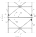
- each prefabricated structure has four columns 20 that run through the framework. Multiple beams are set between adjacent columns 20 and both ends of each beam are connected to a corresponding column 20. Inter-beam supports that are parallel to beams are set between adjacent beams and both ends of an inter-beam support are connected to a corresponding column 20. One end of each oblique support is connected to the middle of an inter-beam support to form a cross-shaped structure and the other end of the oblique support is connected to the joint between a corresponding column 20 and a beam or ring beam 30.
- the ring beam 30 is located at the joining end of a prefabricated structure, for example, the bottom of an upper prefabricated structure 11 and top of a lower prefabricated structure 12.
- a steel frame structure 70 is set to make the frame structure 70 be fixed on the inner side of a first panel 51 of the framework and surround the outer sides of columns 20.
- the ring beam 30 is connected and fixed on the frame structure 70 to form a continuous entirety.
- the direction of the joining end of each prefabricated structure is different. Therefore, the joining surface of the ring beam 30 is its bottom or top.
- the top or bottom of the ring beam 30 opposite to the joining surface is called the non-joining surface.
- mounting holes are set on the joining surface of each ring beam 30 to install a first bolt 41 and a second bolt 42 during field assembly and connect ring beams 30 of adjacent prefabricated structures.
- the first bolt 41 is installed in a location (for example, a corner) corresponding to a column 20 on the joining surface of the ring beam 30 and the second bolt 42 is installed in another location on the joining surface of the ring beam 30.
- the spacing of the first bolt 41 is smaller than the spacing of the second bolt 42.
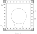
- a connecting plate 80 is set on the outer side of the location corresponding to a column 20 on the ring beam 30, a connecting plate 80 is set.
- Each connecting plate 80 extends from the joining surface of the ring beam 30 to the non-joining surface.
- the connecting plates 80 of two adjacent prefabricated structures may contact each other after they are joined but do not need to be fixed through welding or bolts.
- first panels 51 In a factory workshop, all sides of frameworks of prefabricated structures are enclosed through several first panels 51 connected with parts such as beams and columns.
- the joining node of the first panel 51 may adopt seal welding to ensure the airtightness.
- the vertical section on any side of the ring beam 30 is I-shaped and a vertical beam is set to fix the joining surface and non-joining surface that are parallel to each other.
- the vertical section on any side of the frame structure 70 is L-shaped and has a first surface and a second surface that are perpendicular to each other.
- the first surface of the frame structure 70 is welded on the inner side of edges of a first panel 51 and the second surface of the frame structure 70 is welded on the non-joining surface of the ring beam 30 and extends towards the inner side of the framework.
- the first surface of the frame structure 70 is basically aligned with the outer edge of the non-joining surface.
- B indicates that the frame structure 70 is connected to the first panel 51 and ring beam 30 through welding.
- Each first panel 51 preferably covers the first surface of the frame structure 70 completely.
- a mounting hole that runs through the two is set and is used to install a third bolt 43 for connecting the second panel 52.
- a washer 60 made of neoprene is set between the second panel 52 and the first panel 51 during field assembly.
- the second panel 52 can cover outer sides of connecting plates 80 (shown in Figure 6 ) of two ring beams 30 after field joining is complete.
- the two ring beams 30 are fixed and connected through the first bolt 41 and second bolt 42 installed on the joining surface.
- FIG. 3 The following describes the process of assembling a skid-mounted cold box on site: As shown in Figure 3 , upper and lower prefabricated structures 11 and 12 are transported to the predetermined site. After the lower prefabricated structure 12 is installed in place, a crane is mobilized to lift the upper prefabricated structure 11, making the joining surfaces of ring beams 30 of the upper and lower prefabricated structure 11 and 12 be aligned and in contact. After the first bolt 41 is installed and fastened in a location corresponding to a column 20 on the surface of the ring beam 30, the crane can be dismissed (or stay on site). Then in another location on the joining surface of the ring beam 30, the second bolt 42 is installed and fastened.
- the frameworks of adjacent prefabricated structures according to the present invention are reliably connected through ring beams 30 connected based on bolts.
- the ring beams 30 are made of carbon steel.
- the first bolt 41 and the second bolt 42 for the ring beam 30 are friction-type high-strength bolts and are used to ensure that relative displacement does not occur between prefabricated structures under the action of wind load.
- the shear force and bending moment generated by the upper prefabricated structure 11 can be transferred to the prefabricated structure 12 under the joint action of the column 20 and ring beam 30 to further enhance the structural stiffness of frameworks.
- each second panel 52 is connected to two prefabricated structures through the second bolt 43 and the second panel 52 is connected to the outer side of the first panel 51 and corresponds to the welding point between the first surface of the frame structure 70 and the first panel 51.
- a washer 60 made of neoprene is set between the second panel 52 and the first panel 51.
- edges of the connecting plates 80 of two ring beams 30 are adjacent or in contact and the second panel 52 directly covers the outer side of the two connecting plates 80 to enclose the gap (corresponding to the gap in corresponding locations of columns 20 on the two ring beams 30) between edges of the two connecting plates 80.
- a cold box with a design height of 30m sizes can be designed for parts such as columns, beams, oblique supports and inter-beam supports according to general requirements.
- the ring beam 30 is I-shaped on any side and the width of the joining surface and non-joining surface is equal to the height of vertical beams.
- the height is 350 mm to 400 mm and is preferably 350 mm.
- ring beams 30 are set in the upper and lower prefabricated structures 11 and 12 in the example. This causes little change to the overall height of the cold box after assembly.
- first bolts 41 on the joining surfaces of ring beams 30 corresponding to columns 20 are densely set.
- first bolts 41 are installed in a corner of a ring beam 30.
- the spacing (200 to 300 mm in this example) of second bolts 42 installed in other locations of the joining surfaces of ring beams 30 is greater than the spacing of first bolts 41 installed in corners.
- the present invention can effectively avoid welding of steeling structures and nondestructive testing during field joining and save relevant costs.
- bolts are used for joining, once the upper prefabricated structure of the cold box is in place and the bolts corresponding to columns on ring beams are connected and fastened, the crane can be dismissed.
- the present invention guarantees sufficient strength relying on bolt-based connection between ring beams and saves field time and measure cost to the maximum extent.
- the second panel is connected through bolts to cover the gap formed between two ring beams after joining.
- a washer is set on the contact surface between the second panel and the first panel to guarantee the airtightness of the cold box.
Landscapes
- Engineering & Computer Science (AREA)
- Architecture (AREA)
- Mechanical Engineering (AREA)
- Physics & Mathematics (AREA)
- Civil Engineering (AREA)
- Structural Engineering (AREA)
- Thermal Sciences (AREA)
- General Engineering & Computer Science (AREA)
- Electromagnetism (AREA)
- Joining Of Building Structures In Genera (AREA)
- Assembled Shelves (AREA)
Claims (9)
- Bauteile, die zur Bildung einer rahmenmontierten Kühlbox zusammenzufügen sind, umfassend eine erste und eine zweite vorgefertigte Struktur (11, 12), die jeweils einen Rahmen umfassen, wobei mehrere durch die Rahmen verlaufende Säulen (20) gesetzt sind, mehrere erste Platten (51), die die Außenseite des Rahmens verbinden, wobei die mehreren ersten Platten den Rahmen und die Außenseiten seiner Säulen vollständig umschließen und ein Ringträger (30) und Befestigungslöcher für Schrauben (41, 42) an dem Ringträger angebracht sind, sodass der Ringträger der ersten vorgefertigten Struktur (11) mit dem ähnlichen Ringträger der zweiten vorgefertigten Struktur (12) verbunden werden kann, um während der Montage durch Schrauben verbunden zu werden;
dadurch gekennzeichnet, dass die Bauteile eine zweite Platte (52) umfassen und dass die erste und die zweite vorgefertigte Struktur beide Folgendes umfassen: eine Rahmenstruktur (70), die an der Innenseite der Kanten der ersten Platten an einem Verbindungsende jeder vorgefertigten Struktur befestigt ist, wobei der Ringträger (30) befestigt ist und Befestigungslöcher für Schrauben, die an der Verbindung zwischen jeder Rahmenstruktur und den ersten Platten angebracht sind, um die zweite Platte durch Schrauben während der Montage und durch die zweite Platte zu verbinden, um auf der Außenseite der ersten Platten den Spalt, der an den Ringträger der ersten und der zweiten vorgefertigten Struktur gebildet wird, nachdem die erste und die zweite vorgefertigte Struktur während der Montage zusammengefügt wurden, vollständig zu schließen. - Bauteile nach Anspruch 1, wobei:der vertikale Abschnitt der Ringträger (30) jeder ersten und zweiten vorgefertigten Struktur (11, 12) I-förmig ist und einen vertikalen Balken, eine Verbindungsfläche und eine Nicht-Verbindungsfläche aufweist, wobei die Verbindungsfläche und die Nicht-Verbindungsfläche an dem vertikalen Balken befestigt und parallel zueinander sind, und der vertikale Abschnitt der Rahmenstruktur jeder ersten und zweiten vorgefertigten Struktur (11, 12) L-förmig ist und eine erste Fläche und eine zweite Fläche aufweist, die rechtwinklig zueinander sind; unddie erste Fläche mit der Innenseite der Kanten der ersten Platte der jeweiligen vorgefertigten Struktur verbunden ist, Befestigungslöcher für Schrauben (41, 42) an der Verbindung angebracht sind, sodass die zweite Platte (52) an der Außenseite jeder ersten Platte (51) durch die Schrauben befestigt werden kann, und die zweite Fläche mit der Nicht-Verbindungsfläche der Ringträger verbunden ist und sich in Richtung der Innenseite des Rahmens erstreckt.
- Bauteile nach Anspruch 2, wobei:
eine Verbindungsplatte (80) an der Außenseite einer Stelle angebracht ist, die einer Säule (20) auf dem Ringträger (30) jeder vorgefertigten Struktur entspricht, und die Verbindungsplatte sich von der Verbindungsfläche des Ringträgers zu der Nicht-Verbindungsfläche erstreckt, sodass die montierte zweite Platte (52) die Verbindungsplatte des Ringträgers abdecken kann, der mit dem anderen Ringträger verbunden ist. - Bauteile nach Anspruch 1, wobei:
Befestigungslöcher für eine erste Schraube (41) und eine zweite Schraube (42) an der Verbindungsfläche des Ringträgers (30) jeder vorgefertigten Struktur angebracht sind, wobei das Befestigungsloch für die erste Schraube an einer Stelle ist, die einer Säule (20) an der Verbindungsfläche des Ringträgers entspricht, und das Befestigungsloch für die zweite Schraube an einer anderen Stelle an der Verbindungsfläche des Ringträgers ist; und der Abstand der Befestigungslöcher für die erste Schraube kleiner als der Abstand der Befestigungslöcher für die zweite Schraube ist. - Bauteile nach Anspruch 1, wobei:
jede Rahmen ferner umfasst:mehrere Balken, die zwischen benachbarten Säulen (20) angeordnet sind, wobei beide Enden jedes Trägers mit entsprechenden Säulen verbunden sind;mehrere Zwischenträgerstützen, die parallel zu den Trägern verlaufen und zwischen benachbarten Trägern angeordnet sind, wobei beide Enden jeder Zwischenträgerstütze mit entsprechenden Säulen verbunden sind; undmehrere Schrägstützen, wobei ein Ende jeder Schrägstütze mit der Mitte einer Zwischenträgerstütze und das andere Ende mit der Verbindung zwischen einer entsprechenden Säule und einem Träger oder Ringträger (30) verbunden ist. - Rahmenmontierte Kühlbox, wobei die rahmenmontierte Kühlbox mindestens eine erste und eine zweite vorgefertigte Struktur (11, 12) und eine zweite Platte (52) aufweist, die durch Schrauben (41, 42, 43) vor Ort verbunden sind;
wobei die mindestens erste und zweite vorgefertigte Struktur und die zweite Platte nach einem der Ansprüche 1 bis 5 ausgeführt sind. - Rahmenmontierte Kühlbox nach Anspruch 6, wobei zwischen der zweiten Platte (52) und einer der ersten Platten (51) eine Unterlegscheibe (60) aus Neopren eingesetzt ist.
- Rahmenmontierte Kühlbox nach Anspruch 6, wobei:
Schrauben (41, 42), die Ringträger (30) in der mindestens ersten und zweiten vorgefertigten Struktur (11, 12) verbinden, hochfeste Reibgriffschrauben sind und der Abstand der Schraube an einer Stelle, die einer Säule auf der Verbindungsfläche eines beliebigen Ringträgers entspricht, kleiner als der Abstand von Schrauben an anderen Stellen auf der Verbindungsfläche des Ringträgers (30) ist. - Verfahren zum Montieren der rahmenmontierten Kühlbox nach einem der Ansprüche 6 bis 8, umfassend den folgenden Prozess:Transportieren der ersten und der zweiten vorgefertigten Struktur (11, 12) als obere und untere vorgefertigte Struktur der Kühlbox zu dem vorbestimmten Ort;Installieren der unteren vorgefertigten Struktur (12);Mobilisieren eines Krans zum Anheben der oberen vorgefertigten Struktur, sodass die Verbindungsflächen der Ringträger (30) der oberen und der unteren vorgefertigten Struktur aufeinander ausgerichtet sind und sich berühren;Einsetzen und Festziehen von Schrauben (41, 42) an Stellen, die den Säulen auf den Verbindungsflächen der Ringträger entsprechen, und selektives Lösen des Krans;Einsetzen und Festziehen von Schrauben an anderen Stellen auf den Verbindungsflächen der Ringträger und Vervollständigen der Rahmenverbindung der oberen und der unteren vorgefertigten Struktur; undVerbinden der zweiten Platte (52) mit der Außenseite der ersten Platten (51) für die obere und die untere vorgefertigte Struktur durch Schrauben und vollständiges Schließen des Spalts, der in den Ringträger der oberen und der unteren vorgefertigten Struktur gebildet wird, die über die zweite Platte verbunden sind.
Applications Claiming Priority (1)
| Application Number | Priority Date | Filing Date | Title |
|---|---|---|---|
| PCT/CN2016/113663 WO2018120091A1 (zh) | 2016-12-30 | 2016-12-30 | 一种撬装式冷箱及其预制结构和装配方法 |
Publications (3)
| Publication Number | Publication Date |
|---|---|
| EP3564608A1 EP3564608A1 (de) | 2019-11-06 |
| EP3564608A4 EP3564608A4 (de) | 2020-08-05 |
| EP3564608B1 true EP3564608B1 (de) | 2024-10-09 |
Family
ID=62707917
Family Applications (1)
| Application Number | Title | Priority Date | Filing Date |
|---|---|---|---|
| EP16925282.2A Active EP3564608B1 (de) | 2016-12-30 | 2016-12-30 | Rahmenmontierte kühlbox, bauteile dafür und montageverfahren dafür |
Country Status (5)
| Country | Link |
|---|---|
| US (1) | US11079177B2 (de) |
| EP (1) | EP3564608B1 (de) |
| CN (1) | CN110088547B (de) |
| AU (1) | AU2016434623B2 (de) |
| WO (1) | WO2018120091A1 (de) |
Families Citing this family (10)
| Publication number | Priority date | Publication date | Assignee | Title |
|---|---|---|---|---|
| USD1017832S1 (en) * | 2020-07-17 | 2024-03-12 | Global Engineers Investment Singapore Pte. Ltd. | Tower |
| USD1095885S1 (en) * | 2020-10-27 | 2025-09-30 | Francisco Javier Alvarez | Modular semi-hexadecagonal structure |
| FR3118453B1 (fr) * | 2020-12-24 | 2023-03-24 | Air Liquide | Enceinte et procédé de construction d’une enceinte d’un appareil de séparation par distillation cryogénique |
| USD970043S1 (en) * | 2021-06-30 | 2022-11-15 | Cignomet OU | Framework for building |
| USD969345S1 (en) * | 2021-06-30 | 2022-11-08 | Cignomet OÜ | Framework for building |
| USD970044S1 (en) * | 2021-06-30 | 2022-11-15 | Cignomet OÜ | Framework for building |
| CN115371358A (zh) * | 2022-07-21 | 2022-11-22 | 杭州福斯达深冷装备股份有限公司 | 空气分离装置及其冷箱组件 |
| CN115218609B (zh) * | 2022-09-20 | 2023-01-06 | 江苏卓然恒泰低温科技有限公司 | 一种柱脚底板分离式大型整体冷箱及其安装方法 |
| CN116857901A (zh) * | 2023-06-05 | 2023-10-10 | 上海二十冶建设有限公司 | 一种空分板式冷箱的分段式制作安装方法 |
| CN120231383B (zh) * | 2025-05-30 | 2025-08-01 | 中建材(合肥)钢构科技有限公司 | 一种模块化钢结构廊道及组合装配方法 |
Family Cites Families (13)
| Publication number | Priority date | Publication date | Assignee | Title |
|---|---|---|---|---|
| DE1103948B (de) * | 1957-11-29 | 1961-04-06 | Linde Eismasch Ag | Luftdichtes isoliertes Gehaeuse fuer Tieftemperaturanlagen mit einem ganz oder teilweise zerlegbaren, beplankten Profilstahltraegergeruest |
| US3648990A (en) * | 1968-11-05 | 1972-03-14 | Robert J Stoker | Cooling tower |
| FR2417066A2 (fr) * | 1978-02-08 | 1979-09-07 | Air Liquide | Ensemble d'echange thermique du genre echangeur de chaleur a plaques |
| US4331252A (en) * | 1980-07-25 | 1982-05-25 | Modutank, Inc. | Modular storage tank |
| JP2003130296A (ja) * | 2001-10-29 | 2003-05-08 | Osaka Gas Co Ltd | Lng管理システム及びその課金システム |
| DE10229663A1 (de) * | 2002-07-02 | 2004-01-22 | Linde Ag | Coldboxblechmantel |
| FR2946075A1 (fr) * | 2009-05-26 | 2010-12-03 | Air Liquide | Element de construction d'une enceinte, enceinte construite utilisant ces elements et procede de construction. |
| CN104006626B (zh) * | 2014-04-15 | 2016-03-02 | 张家港富瑞特种装备股份有限公司 | 一种液化天然气的预制冷剂压缩撬装模块 |
| CN204535232U (zh) * | 2015-03-26 | 2015-08-05 | 郑州大学 | 一种撬装式移动冷库 |
| CN205770668U (zh) * | 2016-01-07 | 2016-12-07 | 常州移动果库复合材料科技有限公司 | 一种六片拼接式流转保冷箱 |
| CN205838941U (zh) * | 2016-07-14 | 2016-12-28 | 浙江省天正设计工程有限公司 | 撬装式天然气重烃精馏装置 |
| CN106223669A (zh) * | 2016-08-19 | 2016-12-14 | 浙江智海化工设备工程有限公司 | 一种空分集装式冷箱 |
| US10087615B1 (en) * | 2017-11-30 | 2018-10-02 | Christie Lites Enterprises Canada Inc. | Connection apparatus |
-
2016
- 2016-12-30 EP EP16925282.2A patent/EP3564608B1/de active Active
- 2016-12-30 US US16/474,121 patent/US11079177B2/en active Active
- 2016-12-30 CN CN201680091519.2A patent/CN110088547B/zh active Active
- 2016-12-30 WO PCT/CN2016/113663 patent/WO2018120091A1/zh not_active Ceased
- 2016-12-30 AU AU2016434623A patent/AU2016434623B2/en not_active Expired - Fee Related
Also Published As
| Publication number | Publication date |
|---|---|
| EP3564608A1 (de) | 2019-11-06 |
| EP3564608A4 (de) | 2020-08-05 |
| WO2018120091A1 (zh) | 2018-07-05 |
| AU2016434623A1 (en) | 2019-07-25 |
| CN110088547A (zh) | 2019-08-02 |
| AU2016434623B2 (en) | 2020-08-13 |
| US11079177B2 (en) | 2021-08-03 |
| CN110088547B (zh) | 2021-03-30 |
| US20190353422A1 (en) | 2019-11-21 |
Similar Documents
| Publication | Publication Date | Title |
|---|---|---|
| EP3564608B1 (de) | Rahmenmontierte kühlbox, bauteile dafür und montageverfahren dafür | |
| CN103015537B (zh) | 一种装配式钢结构体系的梁柱节点连接装置 | |
| CN105569189B (zh) | 一种模块化多高层钢结构异形柱梁柱节点连接装置 | |
| CN107386462A (zh) | 单边屈曲约束式钢梁柱连接节点和钢结构建筑 | |
| CN106812214A (zh) | 一种装配式钢结构梁柱节点连接装置 | |
| CN108457374A (zh) | 一种箱型梁与柱连接装配式节点制备工艺及其节点 | |
| CN105926811A (zh) | 一种多盖板装配式两端连接钢板剪力墙节点 | |
| CN107806180A (zh) | 一种装配式钢结构方钢管柱梁柱节点t型盖板连接装置 | |
| CN104264792B (zh) | 一种分层装配式钢结构的梁柱节点 | |
| CN107574924A (zh) | 一种用于钢接头连接的装配式混凝土框架的构件及施工方法 | |
| CN107574923A (zh) | 一种采用钢接头连接的预制装配式混凝土框架 | |
| CN105088971A (zh) | 一种波形钢腹板pc箱梁斜拉桥中跨合龙施工方法 | |
| CN202788024U (zh) | 一种高刚度混凝土梁结构 | |
| CN207260341U (zh) | 单边屈曲约束式钢梁柱连接节点和钢结构建筑 | |
| JP2010132415A (ja) | クレーン補修方法および補修クレーン | |
| CN205577400U (zh) | 一种工具式模板 | |
| CN102425269A (zh) | 可悬吊重物的大板梁及其构筑方法 | |
| CN102019512B (zh) | T形柱对接焊施工方法 | |
| CN213329418U (zh) | 一种改进型全栓接装配式梁柱节点 | |
| CN219638481U (zh) | 在已有钢柱新增管道梁的节点结构 | |
| CN212001585U (zh) | 一种箱型钢梁内外搭接的结构 | |
| CN103882949B (zh) | 多高层装配式钢结构咬合钢梁预应力中心支撑体系 | |
| KR20230123383A (ko) | 격자형 수직 스티프너가 구성된 기둥-강재 거더 접합용 내다이아프램부재 | |
| CN207376809U (zh) | 一种大悬挑钢结构高空无支撑安装临时加固装置 | |
| CN223548718U (zh) | 一种u形钢混凝土组合梁-钢管混凝土柱搭接式节点 |
Legal Events
| Date | Code | Title | Description |
|---|---|---|---|
| STAA | Information on the status of an ep patent application or granted ep patent |
Free format text: STATUS: THE INTERNATIONAL PUBLICATION HAS BEEN MADE |
|
| PUAI | Public reference made under article 153(3) epc to a published international application that has entered the european phase |
Free format text: ORIGINAL CODE: 0009012 |
|
| STAA | Information on the status of an ep patent application or granted ep patent |
Free format text: STATUS: REQUEST FOR EXAMINATION WAS MADE |
|
| 17P | Request for examination filed |
Effective date: 20190730 |
|
| AK | Designated contracting states |
Kind code of ref document: A1 Designated state(s): AL AT BE BG CH CY CZ DE DK EE ES FI FR GB GR HR HU IE IS IT LI LT LU LV MC MK MT NL NO PL PT RO RS SE SI SK SM TR |
|
| AX | Request for extension of the european patent |
Extension state: BA ME |
|
| DAV | Request for validation of the european patent (deleted) | ||
| DAX | Request for extension of the european patent (deleted) | ||
| REG | Reference to a national code |
Ref country code: DE Ref legal event code: R079 Free format text: PREVIOUS MAIN CLASS: F25J0003000000 Ipc: F25J0003040000 Ref document number: 602016089816 Country of ref document: DE |
|
| A4 | Supplementary search report drawn up and despatched |
Effective date: 20200708 |
|
| RIC1 | Information provided on ipc code assigned before grant |
Ipc: F25J 1/00 20060101ALI20200702BHEP Ipc: E04H 5/10 20060101ALI20200702BHEP Ipc: F25J 1/02 20060101ALI20200702BHEP Ipc: F25J 3/04 20060101AFI20200702BHEP Ipc: F25J 3/02 20060101ALI20200702BHEP |
|
| STAA | Information on the status of an ep patent application or granted ep patent |
Free format text: STATUS: EXAMINATION IS IN PROGRESS |
|
| 17Q | First examination report despatched |
Effective date: 20210429 |
|
| GRAP | Despatch of communication of intention to grant a patent |
Free format text: ORIGINAL CODE: EPIDOSNIGR1 |
|
| STAA | Information on the status of an ep patent application or granted ep patent |
Free format text: STATUS: GRANT OF PATENT IS INTENDED |
|
| INTG | Intention to grant announced |
Effective date: 20240507 |
|
| GRAS | Grant fee paid |
Free format text: ORIGINAL CODE: EPIDOSNIGR3 |
|
| GRAA | (expected) grant |
Free format text: ORIGINAL CODE: 0009210 |
|
| STAA | Information on the status of an ep patent application or granted ep patent |
Free format text: STATUS: THE PATENT HAS BEEN GRANTED |
|
| AK | Designated contracting states |
Kind code of ref document: B1 Designated state(s): AL AT BE BG CH CY CZ DE DK EE ES FI FR GB GR HR HU IE IS IT LI LT LU LV MC MK MT NL NO PL PT RO RS SE SI SK SM TR |
|
| REG | Reference to a national code |
Ref country code: CH Ref legal event code: EP |
|
| REG | Reference to a national code |
Ref country code: DE Ref legal event code: R096 Ref document number: 602016089816 Country of ref document: DE |
|
| REG | Reference to a national code |
Ref country code: IE Ref legal event code: FG4D |
|
| REG | Reference to a national code |
Ref country code: NL Ref legal event code: FP |
|
| REG | Reference to a national code |
Ref country code: LT Ref legal event code: MG9D |
|
| REG | Reference to a national code |
Ref country code: AT Ref legal event code: MK05 Ref document number: 1730987 Country of ref document: AT Kind code of ref document: T Effective date: 20241009 |
|
| PG25 | Lapsed in a contracting state [announced via postgrant information from national office to epo] |
Ref country code: IS Free format text: LAPSE BECAUSE OF FAILURE TO SUBMIT A TRANSLATION OF THE DESCRIPTION OR TO PAY THE FEE WITHIN THE PRESCRIBED TIME-LIMIT Effective date: 20250209 Ref country code: HR Free format text: LAPSE BECAUSE OF FAILURE TO SUBMIT A TRANSLATION OF THE DESCRIPTION OR TO PAY THE FEE WITHIN THE PRESCRIBED TIME-LIMIT Effective date: 20241009 Ref country code: PT Free format text: LAPSE BECAUSE OF FAILURE TO SUBMIT A TRANSLATION OF THE DESCRIPTION OR TO PAY THE FEE WITHIN THE PRESCRIBED TIME-LIMIT Effective date: 20250210 |
|
| PG25 | Lapsed in a contracting state [announced via postgrant information from national office to epo] |
Ref country code: FI Free format text: LAPSE BECAUSE OF FAILURE TO SUBMIT A TRANSLATION OF THE DESCRIPTION OR TO PAY THE FEE WITHIN THE PRESCRIBED TIME-LIMIT Effective date: 20241009 |
|
| PG25 | Lapsed in a contracting state [announced via postgrant information from national office to epo] |
Ref country code: BG Free format text: LAPSE BECAUSE OF FAILURE TO SUBMIT A TRANSLATION OF THE DESCRIPTION OR TO PAY THE FEE WITHIN THE PRESCRIBED TIME-LIMIT Effective date: 20241009 |
|
| PG25 | Lapsed in a contracting state [announced via postgrant information from national office to epo] |
Ref country code: ES Free format text: LAPSE BECAUSE OF FAILURE TO SUBMIT A TRANSLATION OF THE DESCRIPTION OR TO PAY THE FEE WITHIN THE PRESCRIBED TIME-LIMIT Effective date: 20241009 |
|
| PG25 | Lapsed in a contracting state [announced via postgrant information from national office to epo] |
Ref country code: NO Free format text: LAPSE BECAUSE OF FAILURE TO SUBMIT A TRANSLATION OF THE DESCRIPTION OR TO PAY THE FEE WITHIN THE PRESCRIBED TIME-LIMIT Effective date: 20250109 |
|
| PG25 | Lapsed in a contracting state [announced via postgrant information from national office to epo] |
Ref country code: LV Free format text: LAPSE BECAUSE OF FAILURE TO SUBMIT A TRANSLATION OF THE DESCRIPTION OR TO PAY THE FEE WITHIN THE PRESCRIBED TIME-LIMIT Effective date: 20241009 Ref country code: GR Free format text: LAPSE BECAUSE OF FAILURE TO SUBMIT A TRANSLATION OF THE DESCRIPTION OR TO PAY THE FEE WITHIN THE PRESCRIBED TIME-LIMIT Effective date: 20250110 Ref country code: AT Free format text: LAPSE BECAUSE OF FAILURE TO SUBMIT A TRANSLATION OF THE DESCRIPTION OR TO PAY THE FEE WITHIN THE PRESCRIBED TIME-LIMIT Effective date: 20241009 |
|
| PG25 | Lapsed in a contracting state [announced via postgrant information from national office to epo] |
Ref country code: PL Free format text: LAPSE BECAUSE OF FAILURE TO SUBMIT A TRANSLATION OF THE DESCRIPTION OR TO PAY THE FEE WITHIN THE PRESCRIBED TIME-LIMIT Effective date: 20241009 |
|
| PG25 | Lapsed in a contracting state [announced via postgrant information from national office to epo] |
Ref country code: RS Free format text: LAPSE BECAUSE OF FAILURE TO SUBMIT A TRANSLATION OF THE DESCRIPTION OR TO PAY THE FEE WITHIN THE PRESCRIBED TIME-LIMIT Effective date: 20250109 |
|
| PG25 | Lapsed in a contracting state [announced via postgrant information from national office to epo] |
Ref country code: SM Free format text: LAPSE BECAUSE OF FAILURE TO SUBMIT A TRANSLATION OF THE DESCRIPTION OR TO PAY THE FEE WITHIN THE PRESCRIBED TIME-LIMIT Effective date: 20241009 |
|
| PG25 | Lapsed in a contracting state [announced via postgrant information from national office to epo] |
Ref country code: MC Free format text: LAPSE BECAUSE OF FAILURE TO SUBMIT A TRANSLATION OF THE DESCRIPTION OR TO PAY THE FEE WITHIN THE PRESCRIBED TIME-LIMIT Effective date: 20241009 |
|
| PG25 | Lapsed in a contracting state [announced via postgrant information from national office to epo] |
Ref country code: DK Free format text: LAPSE BECAUSE OF FAILURE TO SUBMIT A TRANSLATION OF THE DESCRIPTION OR TO PAY THE FEE WITHIN THE PRESCRIBED TIME-LIMIT Effective date: 20241009 |
|
| REG | Reference to a national code |
Ref country code: DE Ref legal event code: R097 Ref document number: 602016089816 Country of ref document: DE |
|
| PG25 | Lapsed in a contracting state [announced via postgrant information from national office to epo] |
Ref country code: EE Free format text: LAPSE BECAUSE OF FAILURE TO SUBMIT A TRANSLATION OF THE DESCRIPTION OR TO PAY THE FEE WITHIN THE PRESCRIBED TIME-LIMIT Effective date: 20241009 |
|
| PG25 | Lapsed in a contracting state [announced via postgrant information from national office to epo] |
Ref country code: RO Free format text: LAPSE BECAUSE OF FAILURE TO SUBMIT A TRANSLATION OF THE DESCRIPTION OR TO PAY THE FEE WITHIN THE PRESCRIBED TIME-LIMIT Effective date: 20241009 |
|
| PG25 | Lapsed in a contracting state [announced via postgrant information from national office to epo] |
Ref country code: SK Free format text: LAPSE BECAUSE OF FAILURE TO SUBMIT A TRANSLATION OF THE DESCRIPTION OR TO PAY THE FEE WITHIN THE PRESCRIBED TIME-LIMIT Effective date: 20241009 |
|
| PG25 | Lapsed in a contracting state [announced via postgrant information from national office to epo] |
Ref country code: CZ Free format text: LAPSE BECAUSE OF FAILURE TO SUBMIT A TRANSLATION OF THE DESCRIPTION OR TO PAY THE FEE WITHIN THE PRESCRIBED TIME-LIMIT Effective date: 20241009 |
|
| PG25 | Lapsed in a contracting state [announced via postgrant information from national office to epo] |
Ref country code: IT Free format text: LAPSE BECAUSE OF FAILURE TO SUBMIT A TRANSLATION OF THE DESCRIPTION OR TO PAY THE FEE WITHIN THE PRESCRIBED TIME-LIMIT Effective date: 20241009 |
|
| REG | Reference to a national code |
Ref country code: CH Ref legal event code: PL |
|
| PLBE | No opposition filed within time limit |
Free format text: ORIGINAL CODE: 0009261 |
|
| STAA | Information on the status of an ep patent application or granted ep patent |
Free format text: STATUS: NO OPPOSITION FILED WITHIN TIME LIMIT |
|
| PG25 | Lapsed in a contracting state [announced via postgrant information from national office to epo] |
Ref country code: LU Free format text: LAPSE BECAUSE OF NON-PAYMENT OF DUE FEES Effective date: 20241230 |
|
| PG25 | Lapsed in a contracting state [announced via postgrant information from national office to epo] |
Ref country code: SE Free format text: LAPSE BECAUSE OF FAILURE TO SUBMIT A TRANSLATION OF THE DESCRIPTION OR TO PAY THE FEE WITHIN THE PRESCRIBED TIME-LIMIT Effective date: 20241009 |
|
| 26N | No opposition filed |
Effective date: 20250710 |
|
| GBPC | Gb: european patent ceased through non-payment of renewal fee |
Effective date: 20250109 |
|
| PG25 | Lapsed in a contracting state [announced via postgrant information from national office to epo] |
Ref country code: GB Free format text: LAPSE BECAUSE OF NON-PAYMENT OF DUE FEES Effective date: 20250109 |
|
| PG25 | Lapsed in a contracting state [announced via postgrant information from national office to epo] |
Ref country code: CH Free format text: LAPSE BECAUSE OF NON-PAYMENT OF DUE FEES Effective date: 20241231 |
|
| PG25 | Lapsed in a contracting state [announced via postgrant information from national office to epo] |
Ref country code: IE Free format text: LAPSE BECAUSE OF NON-PAYMENT OF DUE FEES Effective date: 20241230 |
|
| PGFP | Annual fee paid to national office [announced via postgrant information from national office to epo] |
Ref country code: DE Payment date: 20251211 Year of fee payment: 10 |
|
| PGFP | Annual fee paid to national office [announced via postgrant information from national office to epo] |
Ref country code: NL Payment date: 20251219 Year of fee payment: 10 Ref country code: FR Payment date: 20251229 Year of fee payment: 10 |
|
| PGFP | Annual fee paid to national office [announced via postgrant information from national office to epo] |
Ref country code: BE Payment date: 20251219 Year of fee payment: 10 |