EP3561571A1 - Optical system and method for adjusting diopter - Google Patents
Optical system and method for adjusting diopter Download PDFInfo
- Publication number
- EP3561571A1 EP3561571A1 EP16925340.8A EP16925340A EP3561571A1 EP 3561571 A1 EP3561571 A1 EP 3561571A1 EP 16925340 A EP16925340 A EP 16925340A EP 3561571 A1 EP3561571 A1 EP 3561571A1
- Authority
- EP
- European Patent Office
- Prior art keywords
- image sensor
- half mirror
- display screen
- image
- stepping motor
- Prior art date
- Legal status (The legal status is an assumption and is not a legal conclusion. Google has not performed a legal analysis and makes no representation as to the accuracy of the status listed.)
- Withdrawn
Links
Images


Classifications
-
- G—PHYSICS
- G02—OPTICS
- G02B—OPTICAL ELEMENTS, SYSTEMS OR APPARATUS
- G02B27/00—Optical systems or apparatus not provided for by any of the groups G02B1/00 - G02B26/00, G02B30/00
- G02B27/01—Head-up displays
- G02B27/017—Head mounted
- G02B27/0172—Head mounted characterised by optical features
-
- G—PHYSICS
- G02—OPTICS
- G02B—OPTICAL ELEMENTS, SYSTEMS OR APPARATUS
- G02B27/00—Optical systems or apparatus not provided for by any of the groups G02B1/00 - G02B26/00, G02B30/00
- G02B27/01—Head-up displays
- G02B27/0101—Head-up displays characterised by optical features
-
- G—PHYSICS
- G02—OPTICS
- G02B—OPTICAL ELEMENTS, SYSTEMS OR APPARATUS
- G02B27/00—Optical systems or apparatus not provided for by any of the groups G02B1/00 - G02B26/00, G02B30/00
- G02B27/0093—Optical systems or apparatus not provided for by any of the groups G02B1/00 - G02B26/00, G02B30/00 with means for monitoring data relating to the user, e.g. head-tracking, eye-tracking
-
- G—PHYSICS
- G02—OPTICS
- G02B—OPTICAL ELEMENTS, SYSTEMS OR APPARATUS
- G02B27/00—Optical systems or apparatus not provided for by any of the groups G02B1/00 - G02B26/00, G02B30/00
- G02B27/01—Head-up displays
-
- G—PHYSICS
- G02—OPTICS
- G02B—OPTICAL ELEMENTS, SYSTEMS OR APPARATUS
- G02B27/00—Optical systems or apparatus not provided for by any of the groups G02B1/00 - G02B26/00, G02B30/00
- G02B27/01—Head-up displays
- G02B27/017—Head mounted
- G02B27/0176—Head mounted characterised by mechanical features
-
- G—PHYSICS
- G02—OPTICS
- G02B—OPTICAL ELEMENTS, SYSTEMS OR APPARATUS
- G02B27/00—Optical systems or apparatus not provided for by any of the groups G02B1/00 - G02B26/00, G02B30/00
- G02B27/10—Beam splitting or combining systems
- G02B27/12—Beam splitting or combining systems operating by refraction only
- G02B27/126—The splitting element being a prism or prismatic array, including systems based on total internal reflection
-
- H—ELECTRICITY
- H04—ELECTRIC COMMUNICATION TECHNIQUE
- H04N—PICTORIAL COMMUNICATION, e.g. TELEVISION
- H04N23/00—Cameras or camera modules comprising electronic image sensors; Control thereof
- H04N23/50—Constructional details
- H04N23/54—Mounting of pick-up tubes, electronic image sensors, deviation or focusing coils
-
- H—ELECTRICITY
- H04—ELECTRIC COMMUNICATION TECHNIQUE
- H04N—PICTORIAL COMMUNICATION, e.g. TELEVISION
- H04N23/00—Cameras or camera modules comprising electronic image sensors; Control thereof
- H04N23/50—Constructional details
- H04N23/55—Optical parts specially adapted for electronic image sensors; Mounting thereof
-
- G—PHYSICS
- G02—OPTICS
- G02B—OPTICAL ELEMENTS, SYSTEMS OR APPARATUS
- G02B27/00—Optical systems or apparatus not provided for by any of the groups G02B1/00 - G02B26/00, G02B30/00
- G02B27/01—Head-up displays
- G02B27/0101—Head-up displays characterised by optical features
- G02B2027/0112—Head-up displays characterised by optical features comprising device for genereting colour display
- G02B2027/0114—Head-up displays characterised by optical features comprising device for genereting colour display comprising dichroic elements
-
- G—PHYSICS
- G02—OPTICS
- G02B—OPTICAL ELEMENTS, SYSTEMS OR APPARATUS
- G02B27/00—Optical systems or apparatus not provided for by any of the groups G02B1/00 - G02B26/00, G02B30/00
- G02B27/01—Head-up displays
- G02B27/0101—Head-up displays characterised by optical features
- G02B2027/0138—Head-up displays characterised by optical features comprising image capture systems, e.g. camera
-
- G—PHYSICS
- G02—OPTICS
- G02B—OPTICAL ELEMENTS, SYSTEMS OR APPARATUS
- G02B27/00—Optical systems or apparatus not provided for by any of the groups G02B1/00 - G02B26/00, G02B30/00
- G02B27/01—Head-up displays
- G02B27/0101—Head-up displays characterised by optical features
- G02B2027/014—Head-up displays characterised by optical features comprising information/image processing systems
-
- G—PHYSICS
- G02—OPTICS
- G02B—OPTICAL ELEMENTS, SYSTEMS OR APPARATUS
- G02B27/00—Optical systems or apparatus not provided for by any of the groups G02B1/00 - G02B26/00, G02B30/00
- G02B27/01—Head-up displays
- G02B27/0179—Display position adjusting means not related to the information to be displayed
- G02B2027/0181—Adaptation to the pilot/driver
-
- G—PHYSICS
- G02—OPTICS
- G02B—OPTICAL ELEMENTS, SYSTEMS OR APPARATUS
- G02B27/00—Optical systems or apparatus not provided for by any of the groups G02B1/00 - G02B26/00, G02B30/00
- G02B27/01—Head-up displays
- G02B27/0179—Display position adjusting means not related to the information to be displayed
- G02B2027/0185—Displaying image at variable distance
-
- G—PHYSICS
- G03—PHOTOGRAPHY; CINEMATOGRAPHY; ANALOGOUS TECHNIQUES USING WAVES OTHER THAN OPTICAL WAVES; ELECTROGRAPHY; HOLOGRAPHY
- G03B—APPARATUS OR ARRANGEMENTS FOR TAKING PHOTOGRAPHS OR FOR PROJECTING OR VIEWING THEM; APPARATUS OR ARRANGEMENTS EMPLOYING ANALOGOUS TECHNIQUES USING WAVES OTHER THAN OPTICAL WAVES; ACCESSORIES THEREFOR
- G03B13/00—Viewfinders; Focusing aids for cameras; Means for focusing for cameras; Autofocus systems for cameras
- G03B13/02—Viewfinders
- G03B13/06—Viewfinders with lenses with or without reflectors
- G03B13/08—Viewfinders with lenses with or without reflectors with reflected image of frame
-
- G—PHYSICS
- G03—PHOTOGRAPHY; CINEMATOGRAPHY; ANALOGOUS TECHNIQUES USING WAVES OTHER THAN OPTICAL WAVES; ELECTROGRAPHY; HOLOGRAPHY
- G03B—APPARATUS OR ARRANGEMENTS FOR TAKING PHOTOGRAPHS OR FOR PROJECTING OR VIEWING THEM; APPARATUS OR ARRANGEMENTS EMPLOYING ANALOGOUS TECHNIQUES USING WAVES OTHER THAN OPTICAL WAVES; ACCESSORIES THEREFOR
- G03B2213/00—Viewfinders; Focusing aids for cameras; Means for focusing for cameras; Autofocus systems for cameras
- G03B2213/02—Viewfinders
- G03B2213/025—Sightline detection
Definitions
- This disclosure relates to the field of an optical system, and more particularly to an optical system and a method for adjusting diopter.
- diopter adjustment of virtual reality (VR) glasses on the market mainly adopts mechanical methods.
- a distance between a display screen and an eyepiece lens can be adjusted by turning a knob to adapt to users of different eyesights.
- Products such as HiSpot, Royole-x, Royole-moon, etc. adopt a mechanical focusing method to adjust diopter. Since operations of manually adjusting diopter are completely based on the users' subjective feeling, adjustment accuracy is difficult to guarantee.
- the present disclosure aims to provide an optical system and a method for adjusting diopter to precisely adjust diopter.
- an optical system in a first aspect of the present disclosure, includes an eyepiece, a half mirror, a display screen, a first stepping motor coupling with the display screen, an image sensor, and an image analysis system coupling with the display screen, the first stepping motor, and the image sensor.
- the eyepiece, the half mirror, and the display screen are sequentially disposed along a first optical axis.
- the half mirror and the image sensor are sequentially disposed along a second optical axis.
- the first stepping motor controls the display screen to move back and forth along the first optical axis.
- Light emitted by the display screen enters an eye through the half mirror and the eyepiece, and light reflected by the eye enters the image sensor through the eyepiece and the half mirror.
- the image sensor converts reflected light signals into fundus images and provides the fundus images to the image analysis system.
- the image analysis system controls the first stepping motor to adjust a distance between the display screen and the half mirror according to the fundus images.
- a method for adjusting diopter is provided.
- the method is applicable to the optical system of the first aspect.
- the method includes the following.
- An image sensor is controlled to collect fundus images.
- a first stepping motor is controlled to adjust a distance between a display screen and a half mirror according to the fundus images.
- a head-mounted display includes the optical system of the first aspect.
- Solution provided by the present disclosure is to adjust the distance between the display screen and the half mirror according to the fundus images obtained by the image sensor, so as to achieve the purpose of adjusting diopter. According to the solution provided by the present disclosure, it is unnecessary for a user to manually adjust diopter, which makes operations more convenient and diopter adjustment more accurate.
- FIG. 1 is a schematic structural diagram illustrating an optical system according to an implementation of the present disclosure.
- the optical system includes an eyepiece 10, a half mirror 20, a display screen 30, a first stepping motor 40 coupled with the display screen 30, an image sensor 50, and an image analysis system 60.
- the image analysis system 60 couples with the display screen 30, the first stepping motor 40, and the image sensor 50.
- the eyepiece 10, the half mirror 20, and the display screen 30 are sequentially disposed along a first optical axis 70.
- the half mirror 20 and the image sensor 50 are sequentially disposed along a second optical axis 80.
- the first stepping motor 40 is configured to control the display screen 30 to move back and forth along the first optical axis 70.
- the image analysis system 60 is configured to control the first stepping motor 40 to adjust a distance between the display screen 30 and the half mirror 20 according to the fundus images, to achieve the purpose of adjusting diopter.
- solution provided by the implementation of the present disclosure is to adjust the distance between the display screen and the half mirror according to the fundus images obtained by the image sensor, to achieve the purpose of adjusting diopter, making it unnecessary for the user to manually adjust diopter, which is convenient for operation and more accurate in adjusting diopter.
- Refraction is a phenomenon in which light is deflected when it propagates through substances with different optical densities.
- the unit of measurement of the refraction is what we usually call "diopter".
- the optical system further includes a second stepping motor 90 coupled with the image sensor 50 and the image analysis system 60.
- the second stepping motor 90 is configured to control the image sensor 50 to move back and forth along the second optical axis 80. When the image sensor 50 moves back and forth along the second optical axis 80, it indicates that the image sensor 50 moves toward or away from the half mirror 20.
- the half mirror 30 may include a beam splitter plate or a beam splitter prism.
- the beam splitter prism is illustrated in FIG. 1 , which is formed when each bevel of two right-angle prisms is plated with a multilayer optical film and the two right-angle prisms are glued to form a cubic structure.
- the beam splitter plate is illustrated in FIG. 2 .
- the first optical axis 70 is perpendicular to the second optical axis 80.
- FIG. 3 is a schematic flow diagram illustrating a method for adjusting diopter according to an implementation of the present disclosure.
- the method includes following steps.
- an image sensor 50 is controlled to collect fundus images.
- the image sensor 50 is controlled to collect the fundus images at S301 as follows: a second stepping motor 90 is controlled to sequentially position the image sensor 50 at N positions, and N fundus images are obtained by controlling the image sensor 50 to collect one fundus image at each of the N positions.
- the N positions correspond to N different distances from the image sensor 50 to the half mirror 20, where N is an integer not less than 1 (that is, N is an integer greater than or equal to 1).
- the image sensor 50 at a first position is closer to the half mirror 20 than the image sensor 50 at an N th position to the half mirror 20.
- the image analysis system 60 first controls the second stepping motor 90 to position the image sensor 50 at an initial position and controls a first stepping motor 40 to position a display screen 30 at an initial position.
- the initial position of the display screen 30 refers to a position where a distance between the display screen 30 and a right surface of the half mirror 20 is d
- the initial position of the image sensor 50 refers to a position where a distance between the image sensor 50 and an upper surface of the half mirror 20 is also d.
- This parameter d i.e., a distance
- the parameter d has been determined when the optical system is designed and the parameter d is equal to a back focal length of the optical system.
- Diopter is 0D when the display screen 30 is at the initial position, where D refers to one unit of diopter, and 1D is equal to 100 degrees of myopia.
- the serial number of a fundus image collected is represented by N .
- a direction from the initial position toward the half mirror 20 is defined as a negative direction and a direction from the initial position away from the half mirror 20 is defined as a positive direction.
- the second stepping motor 90 operates in synchronization with the first stepping motor 40 such that the distance between the image sensor 50 and the half mirror 20 is equal to the distance between the display screen 30 and the half mirror 20.
- the first stepping motor 40 is controlled to adjust a distance between the display screen 30 and the half mirror 20 according to the fundus images.
- the first stepping motor 40 is controlled to adjust the distance between the display screen 30 and the half mirror 20 according to the fundus images at S302 as follows. Definitions of the N fundus images are obtained by analyzing the N fundus images. A fundus image with the highest definition is obtained from the N fundus images, and the fundus image with the highest definition is defined as a target fundus image. A target distance, corresponding to a position where the target fundus image is collected, from the image sensor 50 to the half mirror 20 is obtained. The distance between the display screen 30 and the half mirror 20 is adjusted to the target distance.
- a beam of light is projected onto fundus of an eye to-be-measured, and a position of a focus of a fundus image passing through a refractive system of the eye to-be-measured varies with refractive states of the eye to-be-measured.
- the first image is collected when the image sensor is at a first distance from the half mirror
- the second image is collected when the image sensor is at a second distance from the half mirror
- the third image is collected when the image sensor is at a third distance from the half mirror.
- diopter that best matches the user's diopter is when the distance between the image sensor 30 and the half mirror is the first distance. Accordingly, when the distance between the display screen 30 and the half mirror 20 is adjusted to the first distance, contents displayed on the display screen 30 and viewed by the eye of the user through the eyepiece is the clearest. That is to say, the image analysis system 60 controls the first stepping motor to adjust the distance between the display screen 30 and the half mirror 20 according to an obtained fundus image with the highest definition.
- any two adjacent distances of the N different distances differ by f ⁇ f /2000 mm, where f is a focal length of the optical system.
- the method before the image sensor is controlled to collect the fundus images, the method further includes following steps.
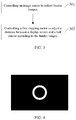
- a picture for adjusting diopter is displayed on the display screen 30, where the picture for adjusting diopter contains a white annular pattern.
- a reflectance of cornea of a human eye is much higher than that of any other part of the human eye, such a difference may cause a large amount of stray light when a fundus image is collected, thereby affecting the quality of the fundus image.
- a picture containing a white annular pattern as illustrated in FIG. 4 is displayed on the display screen 30 before the fundus images are collected, which aims to form an annular light source.
- the picture illustrated in FIG. 4 is black except for the white annular pattern locating in the middle of the picture.
- the white annular pattern has an inner diameter of 3 mm to 5 mm and an outer diameter larger than or equal to 7 mm.
- Implementations of the present disclosure further provide a head-mounted display.
- the head-mounted display includes parts or all of the configurations of any of the optical system described in the above apparatus implementations.
- Implementations of the present disclosure further provide a computer storage medium.
- the computer storage medium may be configured to store programs which, when executed, include parts or all of the operations of any of the method for adjusting diopter described in the above method implementations.
Landscapes
- Physics & Mathematics (AREA)
- General Physics & Mathematics (AREA)
- Optics & Photonics (AREA)
- Engineering & Computer Science (AREA)
- Multimedia (AREA)
- Signal Processing (AREA)
- Eye Examination Apparatus (AREA)
- Telescopes (AREA)
Applications Claiming Priority (1)
| Application Number | Priority Date | Filing Date | Title |
|---|---|---|---|
| PCT/CN2016/112127 WO2018119583A1 (zh) | 2016-12-26 | 2016-12-26 | 光学系统及调节屈光度的方法 |
Publications (1)
| Publication Number | Publication Date |
|---|---|
| EP3561571A1 true EP3561571A1 (en) | 2019-10-30 |
Family
ID=62137033
Family Applications (1)
| Application Number | Title | Priority Date | Filing Date |
|---|---|---|---|
| EP16925340.8A Withdrawn EP3561571A1 (en) | 2016-12-26 | 2016-12-26 | Optical system and method for adjusting diopter |
Country Status (6)
Families Citing this family (5)
| Publication number | Priority date | Publication date | Assignee | Title |
|---|---|---|---|---|
| CN114384697A (zh) * | 2020-10-16 | 2022-04-22 | 舜宇光学(浙江)研究院有限公司 | 近眼显示光学装置及其方法和近眼显示设备 |
| KR102511062B1 (ko) * | 2020-11-26 | 2023-03-17 | 한국과학기술연구원 | 증강현실 광학 장치 |
| CN114202499B (zh) * | 2021-06-22 | 2022-09-09 | 深圳盛达同泽科技有限公司 | 屈光信息测量方法、装置及计算机可读存储介质 |
| CN115061269B (zh) * | 2022-06-30 | 2025-02-25 | 上海微觅医疗器械有限公司 | 屈光度调节装置、方法、观察控制台和计算机设备 |
| CN115268072A (zh) * | 2022-07-12 | 2022-11-01 | 瑞芯微电子股份有限公司 | 用于抬头显示的装置和方法、电子设备和存储介质 |
Family Cites Families (20)
| Publication number | Priority date | Publication date | Assignee | Title |
|---|---|---|---|---|
| JPH08286144A (ja) * | 1995-04-14 | 1996-11-01 | Canon Inc | 画像観察装置及びそれを用いた観察機器 |
| JPH10307314A (ja) * | 1997-05-09 | 1998-11-17 | Canon Inc | 観察光学装置 |
| US7542210B2 (en) * | 2006-06-29 | 2009-06-02 | Chirieleison Sr Anthony | Eye tracking head mounted display |
| JP2009164700A (ja) * | 2007-12-28 | 2009-07-23 | Nikon Corp | 電子ビューファインダおよび電子ビューファインダを有する光学機器 |
| JP5179894B2 (ja) * | 2008-02-15 | 2013-04-10 | 株式会社トプコン | 眼科装置 |
| CN101782369B (zh) * | 2009-01-16 | 2012-09-19 | 鸿富锦精密工业(深圳)有限公司 | 影像量测对焦系统及方法 |
| JP2010233998A (ja) * | 2009-03-31 | 2010-10-21 | Nidek Co Ltd | 眼科装置 |
| JP2014083231A (ja) * | 2012-10-24 | 2014-05-12 | Canon Inc | 眼科装置および眼科制御方法並びにプログラム |
| US10241623B2 (en) * | 2013-03-14 | 2019-03-26 | Neodrón Limited | Reduction of touch sensor pattern visibility using beamsplitters |
| US9549669B2 (en) * | 2013-06-06 | 2017-01-24 | 6 Over 6 Vision Ltd. | System and method for measurement of refractive error of an eye based on subjective distance metering |
| CN103487939B (zh) * | 2013-08-28 | 2016-04-20 | 成都理想境界科技有限公司 | 可调头戴显示光学系统及其调节方法 |
| TW201516467A (zh) * | 2013-10-25 | 2015-05-01 | Quanta Comp Inc | 頭戴式顯示裝置及其成像方法 |
| JP6294722B2 (ja) * | 2014-03-25 | 2018-03-14 | 株式会社トプコン | 眼科装置 |
| JP6354979B2 (ja) * | 2014-03-31 | 2018-07-11 | 株式会社ニデック | 眼底撮影装置 |
| JP2016007433A (ja) * | 2014-06-25 | 2016-01-18 | 株式会社ニデック | 眼科装置 |
| CN104914575B (zh) * | 2014-09-29 | 2017-11-14 | 北京蚁视科技有限公司 | 带有屈光度检测装置的微透镜阵列式近眼显示器 |
| CN204855137U (zh) * | 2015-02-15 | 2015-12-09 | 杭州市质量技术监督检测院 | 一种用于渐进多焦点镜片屈光度的检测装置 |
| WO2016191950A1 (zh) * | 2015-05-29 | 2016-12-08 | 深圳市柔宇科技有限公司 | 显示调节的方法及头戴式显示设备 |
| CN105068248A (zh) * | 2015-08-03 | 2015-11-18 | 众景视界(北京)科技有限公司 | 头戴式全息智能眼镜 |
| CN106175661A (zh) * | 2016-07-12 | 2016-12-07 | 苏州四海通仪器有限公司 | 眼底相机及其光学系统 |
-
2016
- 2016-12-26 JP JP2019530380A patent/JP2020501191A/ja active Pending
- 2016-12-26 CN CN201680049302.5A patent/CN108064355A/zh active Pending
- 2016-12-26 KR KR1020197019621A patent/KR20190090857A/ko not_active Ceased
- 2016-12-26 WO PCT/CN2016/112127 patent/WO2018119583A1/zh active Application Filing
- 2016-12-26 EP EP16925340.8A patent/EP3561571A1/en not_active Withdrawn
-
2019
- 2019-06-21 US US16/448,168 patent/US20190302462A1/en not_active Abandoned
Also Published As
| Publication number | Publication date |
|---|---|
| US20190302462A1 (en) | 2019-10-03 |
| KR20190090857A (ko) | 2019-08-02 |
| JP2020501191A (ja) | 2020-01-16 |
| CN108064355A (zh) | 2018-05-22 |
| WO2018119583A1 (zh) | 2018-07-05 |
Similar Documents
| Publication | Publication Date | Title |
|---|---|---|
| US20190302462A1 (en) | Optical system and method for adjusting diopter | |
| US10048750B2 (en) | Content projection system and content projection method | |
| CN105192982B (zh) | 可调节式虚拟现实头盔的图像矫正方法和系统 | |
| US9867532B2 (en) | System for detecting optical parameter of eye, and method for detecting optical parameter of eye | |
| US9961257B2 (en) | Imaging to facilitate object gaze | |
| US10002293B2 (en) | Image collection with increased accuracy | |
| US20190310477A1 (en) | Head-mounted Display Device and Adjustment Parameter Determining Method for Head-mounted Display Device | |
| WO2015014059A1 (zh) | 成像装置及成像方法 | |
| CN110786822B (zh) | 主觉式验光装置及主觉式验光程序 | |
| CN201920702U (zh) | 免散瞳数字眼底相机及与之相应的瞳孔定位系统 | |
| CN109452928B (zh) | 一种采用云技术基于瞳孔图像采集的镜片位移验光系统 | |
| JP6939815B2 (ja) | 観察システムおよび観察制御プログラム | |
| CN104090371A (zh) | 一种3d眼镜及3d显示系统 | |
| EP4435492A1 (en) | Inter-pupilary distance adjustment method, head-mounted display device and readable storage medium | |
| US12118145B2 (en) | Electronic apparatus | |
| JP2017086652A (ja) | 自覚式検眼装置 | |
| JP6509170B2 (ja) | 画像表示装置 | |
| WO2015046466A1 (ja) | 眼鏡装用パラメータ測定装置、および眼鏡装用パラメータ測定用プログラム | |
| KR102247988B1 (ko) | 자각식 안굴절력 측정 장치 | |
| JP3143553B2 (ja) | ファインダー装置 | |
| CN110401831B (zh) | 一种vr设备及其显示控制方法 | |
| CN110794590A (zh) | 虚拟现实显示系统及其显示方法 | |
| JP2011145358A (ja) | 多焦点電子眼鏡 | |
| JP2018171140A (ja) | 自覚式検眼装置及び自覚式検眼プログラム | |
| CN222838276U (zh) | 激光光轴同步追踪望远镜光轴的双筒测距望远镜光学系统 |
Legal Events
| Date | Code | Title | Description |
|---|---|---|---|
| PUAI | Public reference made under article 153(3) epc to a published international application that has entered the european phase |
Free format text: ORIGINAL CODE: 0009012 |
|
| 17P | Request for examination filed |
Effective date: 20190625 |
|
| AK | Designated contracting states |
Kind code of ref document: A1 Designated state(s): AL AT BE BG CH CY CZ DE DK EE ES FI FR GB GR HR HU IE IS IT LI LT LU LV MC MK MT NL NO PL PT RO RS SE SI SK SM TR |
|
| AX | Request for extension of the european patent |
Extension state: BA ME |
|
| STAA | Information on the status of an ep patent application or granted ep patent |
Free format text: STATUS: THE APPLICATION HAS BEEN WITHDRAWN |
|
| 18W | Application withdrawn |
Effective date: 20191106 |