EP3560737B1 - Luftreinigungsvorrichtung, verfahren zur steuerung der vorrichtung, einrichtung zur steuerung der vorrichtung und fahrzeug mit verwendung davon - Google Patents
Luftreinigungsvorrichtung, verfahren zur steuerung der vorrichtung, einrichtung zur steuerung der vorrichtung und fahrzeug mit verwendung davon Download PDFInfo
- Publication number
- EP3560737B1 EP3560737B1 EP19169879.4A EP19169879A EP3560737B1 EP 3560737 B1 EP3560737 B1 EP 3560737B1 EP 19169879 A EP19169879 A EP 19169879A EP 3560737 B1 EP3560737 B1 EP 3560737B1
- Authority
- EP
- European Patent Office
- Prior art keywords
- air
- module
- vehicle
- main body
- purification apparatus
- Prior art date
- Legal status (The legal status is an assumption and is not a legal conclusion. Google has not performed a legal analysis and makes no representation as to the accuracy of the status listed.)
- Active
Links
Images




Classifications
-
- B—PERFORMING OPERATIONS; TRANSPORTING
- B60—VEHICLES IN GENERAL
- B60H—ARRANGEMENTS OF HEATING, COOLING, VENTILATING OR OTHER AIR-TREATING DEVICES SPECIALLY ADAPTED FOR PASSENGER OR GOODS SPACES OF VEHICLES
- B60H1/00—Heating, cooling or ventilating devices
- B60H1/24—Ventilating devices where the heating or cooling is irrelevant
- B60H1/241—Ventilating devices where the heating or cooling is irrelevant characterised by the location of ventilation devices in the vehicle
- B60H1/245—Ventilating devices where the heating or cooling is irrelevant characterised by the location of ventilation devices in the vehicle located in the roof
-
- B—PERFORMING OPERATIONS; TRANSPORTING
- B60—VEHICLES IN GENERAL
- B60H—ARRANGEMENTS OF HEATING, COOLING, VENTILATING OR OTHER AIR-TREATING DEVICES SPECIALLY ADAPTED FOR PASSENGER OR GOODS SPACES OF VEHICLES
- B60H3/00—Other air-treating devices
-
- B—PERFORMING OPERATIONS; TRANSPORTING
- B60—VEHICLES IN GENERAL
- B60H—ARRANGEMENTS OF HEATING, COOLING, VENTILATING OR OTHER AIR-TREATING DEVICES SPECIALLY ADAPTED FOR PASSENGER OR GOODS SPACES OF VEHICLES
- B60H3/00—Other air-treating devices
- B60H3/06—Filtering
- B60H3/0608—Filter arrangements in the air stream
- B60H3/0641—Filter arrangements in the air stream near ventilating openings in the vehicle exterior
Definitions
- the present invention relates to the technical field of vehicle, and more particularly to an air purification apparatus, a method of controlling the air purification apparatus, a device of controlling the air purification apparatus and a vehicle using the air purification apparatus.
- Air quality inside a vehicle directly influences the health and mood of a passenger.
- it is usually to dispose an air purification apparatus inside the vehicle to circulate and purify the air inside the vehicle, so as to improve the air quality inside the vehicle.
- it is difficult to achieve desired effect simply by circulating and purifying the air inside the vehicle.
- the installation position and power source type of the air purification apparatus directly influence the purification effect. Therefore, how to improve the purification effect of the air purification apparatus in structure view has become a hot issue in current research.
- JP 2001 301451 A for example refers to an air cleaner for a vehicle.
- a deodorizing filter used for the air cleaner is constituted by attaching photocatalyst particles to an adsorbent composed of a porous material for adsorbing odor component in the air.
- a grill provided at an air outlet is constituted so that sunshine streaming in a car interior through the rear window can be let inside the air cleaner.
- the grill is provided so as to tilt in a direction of the rear window of the vehicle roughly at tilt angle of 45 degrees to the rear tray.
- FR 2 903 345 A1 refers to a device for preventilating, ventilating, heating and/or air-conditioning the cabin of a vehicle.
- This device comprises a casing housing a blower and a Peltier-effect thermoelectric unit and comprises at least one air intake for air originating inside and/or outside the cabin, and at least one air outlet towards the inside and/or the outside of the cabin.
- the casing comprises an air discharge duct, which runs between an air intake and an air outlet, and a duct for heat-treating the air, which fully houses the thermoelectric unit and which runs between an air intake and an air outlet.
- KR 2015 0116800 A refers to provides an air cleaning device installed on a ceiling of a vehicle wherein the air cleaning device sterilizes a filter member.
- the air cleaning device comprises a console body installed on an inner ceiling of a vehicle, an inhalation unit formed on an external wall of the console body exposed to an inner space of the vehicle, and a discharging unit formed on an external wall of the console body, wherein air inside the vehicle inhaled from the inhalation unit is discharged through the discharging unit after the air is purified.
- the magnitude of an inhalation speed vector of the air inhaled from the inhalation unit is smaller than the magnitude of a discharging speed vector of the air discharged from the discharging unit.
- a vector sum of the inhalation speed vector of the air inhaled from the inhalation unit and the discharging speed vector of the air discharged from the discharging unit is oriented in a slant direction at higher than -45 degrees and lower than 45 degrees.
- DE 42 22 508 C1 discloses an automobile sliding roof incorporating a ventilation fan. The sliding roof is adjusted between a closed position in which it covers a roof opening and a position in which the greening is at least partially open. The incorporated ventilation fan draws air from the space beneath the roof panel. The ventilation fan is supported by a mounting provided by the rear part of the frame enclosing the roof opening.
- WO 2017/149442 A1 provides a positive pressure vent for a vehicle.
- the vent includes an inlet chamber having an air intake port facing into an air stream generated by motion of the vehicle so as to collect air and form a positive pressure inside the inlet chamber.
- a filter adapted to filter air from the inlet chamber of particulate matter.
- a filtered air path is further provided for allowing filtered air from the filter to travel to the interior of the vehicle under the urging of the positive pressure from the inlet chamber.
- JP 2007 022354 A provides a vehicular ceiling structure comprising a vehicular roof portion provided with a sun roof having a guide rail holding a roof opening/closing element so as to open/close, and a ceiling module attached to a lower surface side of the roof portion. To the guide rail, a drain hose for discharging rain water is attached.
- the ceiling module has a first duct portion fixed on an upper surface of a ceiling board main body.
- the roof portion is provided with a duct storage portion storing a duct, and a second duct portion structuring the other part of the duct is attached to the duct storage portion above the drain hose.
- the first portion and the second portion are coupled with each other to form the duct.
- the present invention provides an air purification apparatus, a control method, a device and a vehicle to enhance the purification effect and overall aesthetics of the air purification apparatus.
- an air purification apparatus i 2. according to claim 1 is provided.
- the main body includes a first side surface and a second side surface disposed opposite to each other, the first side surface is provided with an air inlet connected with the air inlet passage, and the second side surface is provided with an air outlet connected with the air outlet passage.
- a position of the air inlet corresponds to that of the air outlet, and a cross-sectional area of the air inlet is the same as that of the air outlet.
- a plurality of air inlets are distributed in an array on the first side surface, and a plurality of air outlets are distributed in an array on the second side surface.
- a cover area of the cover plate is larger than or equal to a cross-sectional area of the first passage, such that the cover plate is capable of opening or closing the first passage when the cover plate slides along the main body.
- the main body further includes a rail disposed above an upper surface of the solar module, and the cover plate is slidably assembled with the rail, to cover at least a portion of at least one of the solar module and the first passage.
- the cover plate includes a light transmitting glass.
- the apparatus further includes a sealing element surrounding the main body and disposed between the sunroof of the vehicle and the main body.
- the sealing element includes an elastic structure.
- a method of controlling the above air purification apparatus includes:
- a device for controlling the above air purification apparatus includes
- a position of the air inlet corresponds to the position of the air outlet, and a cross-sectional area of the air inlet is the same as the cross-sectional area of the air outlet.
- a program product having computer instructions thereon for execution by a processor to realize the above method.
- a system comprises a processor; and a peripheral controller coupled to the processor, the processor adapted to access data from the peripheral controller, the peripheral controller comprising the above air purification apparatus.
- the main body further comprises a first side surface and a second side surface disposed opposite to each other, the first side surface is provided with an air inlet connected with the air inlet passage, and the second side surface is provided with an air outlet connected with the air outlet passage.
- a position of the air inlet corresponds to the position of the air outlet, and a cross-sectional area of the air inlet is the same as the cross-sectional area of the air outlet.
- a plurality of air inlets are distributed in an array on the first side surface, and a plurality of air outlets are distributed in an array on the second side surface.
- a cover area of the cover plate is larger than or equal to a cross-sectional area of the first passage, such that the cover plate is capable of opening or closing the first passage when the cover plate slides along the main body.
- the main body further comprises a rail disposed above an upper surface of the solar module, and the cover plate is slidably assembled with the rail, to cover at least a portion of at least one of the solar module and the first passage.
- a vehicle which includes a vehicle body and the air purification apparatus above, wherein a sunroof is provided on the vehicle body, and the air purification apparatus is disposed outside the vehicle and covers the sunroof.
- the present invention provides a solar module connected with the main body for the air purification apparatus, to provide power source for the main body, which reduces complicated power lines, and is energy-saving and environmentally friendly.
- the air inlet module and the air outlet module are also provided for the main body of the air purification apparatus, such that the purification module of the main body may inhale the air outside the vehicle, purify it, and discharge the exhaust air from the vehicle, thereby improving the purification effect.
- the air purification apparatus is installed outside the sunroof of the vehicle, the first passage of the main body is connected with the sunroof, and the switch of the first passage is controlled by the sliding of the cover plate. When the first passage is closed, the purification effect is enhanced in virtue of the airflow advantage, and when the first passage is opened, the first passage is connected to the sunroof, so as to easily use the sunroof when the outside air of the vehicle is good.
- an air purification apparatus is usually installed on the seat or the front console of the vehicle, wherein the air purification apparatus is connected with the vehicle power source, and the air quality is improved by circulating and purifying the air inside the vehicle.
- the air purification apparatus in the related art circulates and purifies the air inside the vehicle, which easily causes accumulation of harmful substances, so it is difficult to achieve the desired air quality;
- the installation position of the air purification apparatus in the related art is limited by the internal structure of the vehicle. For example, when the air purification apparatus is installed on the vehicle seat, the air flow is easily blocked by the structure of the seat and the like, so the air flow effect and the purification quality are reduced.
- the air purification apparatus in the related art may need to be connected to the vehicle power source, which occupies the vehicle power resource and increases the complexity of the connecting circuit, and influences the overall aesthetics.
- various embodiments of the present invention improves the structure of the air purification apparatus, which is described as follows.
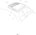
- FIG. 1 is a structural schematic diagram of an air purification apparatus according to some embodiments.
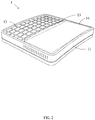
- the air purification apparatus is applied to a vehicle, and includes: a main body 11 and a solar module 12, wherein the solar module 12 covers at least a portion of the main body 11 and connects to the main body 11, for providing power to the main body 11.
- Providing power for the work of the main body 11 by the solar module 12 saves vehicle power source, and reduces connection lines, thereby improving the overall aesthetics of the air purification apparatus 1 and the inside of the vehicle.
- the main body 11 further includes a purification module 112, an air inlet module 111 and an air outlet module 113.
- An air inlet passage 1112 of the air inlet module 111 connects the purification module 112 and the outside of the vehicle, to inhale air from the outside of the vehicle and purify the inhaled air.
- An air outlet passage 1132 of the air outlet module 113 is able to connect the inside and the outside of the vehicle, to discharge the air from the vehicle.
- the main body 11 is assembled on a sunroof of the vehicle, and includes a first passage 14 connected with the sunroof of the vehicle (See FIG. 2 ).
- the air purification apparatus 1 further includes a cover plate 13 that is slidably assembled with the main body 11, and the first passage 14 can be opened or closed by the sliding of the cover plate 13 along the main body 11.
- the purification module 112 of the main body 11 may inhale the air outside the vehicle, purify the inhaled air, and discharge the exhaust air from the vehicle, thereby improving the purification effect.
- the air purification apparatus 1 is installed outside corresponding to the sunroof of the vehicle, the first passage 14 of the main body 11 is connected with the sunroof, and the switch of the first passage 14 is controlled by the sliding of the cover plate 13, such that the purification effect is enhanced in virtue of the airflow advantage when the first passage 14 is closed, and the first passage 14 is connected with the sunroof when the first passage 14 is opened, so as to use the sunroof when the outside air of the vehicle is good.
- the present invention provides improvement on the setting of the air inlet module 111 and the air outlet module 113 that influence the air flow:
- the main body 11 of the air purification apparatus 1 may include a first side surface 114 and a second side surface 115 disposed opposite to each other.
- the first side surface 114 is provided with an air inlet 1111 connected with the air inlet passage 1112
- the second side surface 115 is provided with an air outlet 1131 connected with the air outlet passage 1132.
- the air inlet 1111 and the air outlet 1131 are disposed on opposite sides of the main body 11, thereby avoiding structural interference between the air inlet passage 1112 and the air outlet passage 1132, and simplifying the structures of the air inlet module 111 and the air outlet module 113, such that the flow efficiency and purification effect of the air are further enhanced.
- the air inlet 1111 and the air outlet 1131 may be disposed on other sides of the main body 11, which can be determined by considering the realization of effects of the air intake and air outlet, and to which the present invention is not limited.
- the position of the air inlet 1111 corresponds to that of the air outlet 1131, and the cross-sectional areas of them are the same.
- the air inlet 1111 and the air outlet 1131 are structurally symmetrical, thereby improving the aesthetics of the air purification apparatus 1, and on the other hand, the air inlet position of the air inlet 1111 and the air outlet position of the air outlet 1131 are symmetrical and have the same cross-sectional area, which increases the controllability of the air flow direction and the air flow rate.
- the air inlets 1111 may be distributed in an array on the first side surface 114
- the air outlets 1131 may be distributed in an array on the second side surface 115.
- the structure aesthetic of the air purification apparatus 1 is further raised by distributing in arrays of the air inlets 1111 and the air outlets 1131.
- the air purification apparatus 1 is further provided with a cover plate 13 that is slidably assembled with the main body 11, and the first passage 14 can be opened or closed by the sliding of the cover plate 13 along the main body 11.
- the structure and arrangement of the cover plate 13 described above may be exemplarily illustrated by the following embodiments.
- the cover area of the cover plate 13 is larger than or equal to the cross-sectional area of the first passage 14, such that the cover plate 13 may open or close the first passage 14 when the cover plate 13 slides along the body 11.
- the cover area of the cover plate 13 is equal to the cross-sectional area of the first passage 14, as shown in FIG. 2 , and when the cover plate 13 slides along the main body 11 to the first passage 14, the first passage 14 is just covered to be closed.
- the above structure reduces the space of the air purification apparatus 1 occupied by the cover plate 13 under the premise of ensuring the function of the cover plate 13.
- the cover area of the cover plate 13 is larger than the cross-sectional area of the first passage 14, as shown in FIG.
- the cover plate 13 slides to the first passage 14, not only the first passage 14 is covered, but also a remaining portion 131 of the cover plate 13 that is assembled with other structures of the main body 11 is formed.
- the assembly of the remaining portion 131 and the main body 11 may increase the installation stability of the cover plate 13, and reduce the assembly difficulty of the cover plate 13.
- the main body 11 may further include a slide rail (Not shown) which is disposed above the upper surface of the solar module 12.
- the first passage 14 of the main body 11 is disposed side by side with the solar module 12, and the cover plate 13 is slidably assembled with the slide rail, so as to cover at least a portion of at least one of the solar module 12 and the first passage 14.
- the slide rail is disposed above the upper surface of the solar module 12, and the space above the solar module 12 is used as the move space for the cover 13 when the cover 13 leaves the first passage 14, such that the structure of the air purification apparatus 1 is compact, which improves the space utilization rate.
- the cover plate 13 may include a light transmitting glass or other light transmitting materials, which may be determined by considering no influence on the operation of the solar module 12, and to which the present invention does not limit.
- the air purification apparatus 1 may further include: a sealing element 15 surrounding the main body 11 and disposed between the sunroof of the vehicle and the main body 11, to form a sealing assembly between the main body 11 and the sunroof of the vehicle, so as to prevent impurity such as rainwater, sand and the like entering the inside of the vehicle through the gap between the main body 11 and the sunroof, wherein the sealing member 15 may be an elastic structure, to form an elastic assembly between the air purification apparatus 1 and the vehicle, thereby increasing the installation stability of the air purification apparatus 1 during running of the vehicle, and avoiding damage due to bumping of the vehicle.
- a sealing element 15 surrounding the main body 11 and disposed between the sunroof of the vehicle and the main body 11, to form a sealing assembly between the main body 11 and the sunroof of the vehicle, so as to prevent impurity such as rainwater, sand and the like entering the inside of the vehicle through the gap between the main body 11 and the sunroof
- the sealing member 15 may be an elastic
- FIG. 5 is a flow chart showing a 1 method of controlling the air purification apparatus above according to some embodiments.
- the air purification apparatus 1 described above may further include a fresh air switch 16 as shown in FIG. 4 , and the method may be implemented by the following steps:
- the user may start the air inlet module, the purification module and the air outlet module of the air purification apparatus through the fresh air switch, to make the air inlet module and the purification module and the air outlet module work synchronously, to inhale the outside air of the vehicle, purify it, then deliver the purified air into the vehicle, and discharge the exhaust air from the vehicle at the same time.
- the above method of controlling the air purification apparatus above is easily operated, which improves the air quality inside the vehicle and the convenience of the user.
- FIG. 6 is a structural block diagram of a control device according to some exemplary embodiments of the present invention.
- the above air purification apparatus 1 may further include a fresh air switch 16, and the control device 60 includes a receiving unit 61 and a sending unit 62, wherein the receiving unit 61 is configured to receive a start signal sent through the fresh air switch 16 from a user; and the sending unit 62 is configured to send a corresponding control signal to air inlet module, purification module and air outlet module, such that the air inlet module, the purification module and the air outlet module work synchronously.
- the air inlet module, the purification module and the air outlet module of the air purification apparatus may be started by the fresh air switch 16, to make that the air inlet module and the purification module and the air outlet module work synchronously, to inhale the outside air of the vehicle and purify it, then deliver the purified air into the vehicle, and discharge the exhaust air from the vehicle.
- the above device of controlling the air purification apparatus above is easily operated, which improves the air quality inside the vehicle and the convenience of the user.
- the present invention further provides a vehicle 2, as shown in FIG. 7 , and the vehicle 2 includes a vehicle body and the above-described air purification apparatus 1.
- a sunroof 21 is disposed on the vehicle body, and the air purification apparatus 1 is disposed outside the vehicle 2 and covers the sunroof 21.
- the above-described structural arrangement not only reduces the internal space of the vehicle 2 occupied by the air purification apparatus 1, but also improves the purification effect and the purification efficiency of the vehicle 2.
- FIG. 8 is a schematic diagram that illustrates a system 2000 wherein a peripheral controller 2040 comprises an air purification apparatus 2050 similar to the air purification apparatus described above.
- FIG. 8 illustrates but one application of the invention, that is the personal computer, but may be replaced by other applications such as a workstation, server, Internet driver or other fabric channels used as a link.
- peripheral controller 2040 is coupled to processor 2020 via a serial or parallel bus 2030.
- Processor 2020 is adapted to access data from peripheral controller 2040 via bus 2030.
- Memory 2010, and display controller 2060 may also be coupled to peripheral controller 2040 via bus 2030.
- Monitor 2070 may also be coupled to display controller 2060.
- Other peripheral devices 2080 such as a mouse, CD-ROM and video, may also be coupled to peripheral controller 2040.
- non-transitory computer readable storage medium including instructions, such as a memory including instructions.
- the instructions are executable by a processor of the above apparatus to perform the above method.
- the non-transitory computer readable storage medium may be a read only memory (ROM), a random access memory (RAM), a compact disc read only memory (CD-ROM), a magnetic tape, a floppy disk, an optical data storage device, and the like.
- the present invention has the following advantages: a solar module connected with the main body for the air purification apparatus, to provide power source for the main body, reduces complicated power lines, and is energy-saving and environmentally friendly.
- the air inlet module and the air outlet module are also provided for the main body of the air purification apparatus, such that the purification module of the main body may inhale the air outside the vehicle, purify it, and discharge the exhaust air from the vehicle, thereby improving the purification effect.
- the air purification apparatus is installed outside the sunroof of the vehicle, the first passage of the main body is connected with the sunroof, and the switch of the first passage is controlled by the sliding of the cover plate. When the first passage is closed, the purification effect is enhanced in virtue of the airflow advantage, and when the first passage is opened, the first passage is connected to the sunroof, so as to easily use the sunroof when the outside air of the vehicle is good.
- first and second are used for descriptive purposes only and are not to be construed as indicating or implying a relative importance or implicitly indicating the number of technical features indicated.
- elements referred to as “first” and “second” may include one or more of the features either explicitly or implicitly.
- a plurality indicates two or more unless specifically defined otherwise.
- the terms “installed,” “connected,” “coupled,” “fixed” and the like shall be understood broadly, and may be either a fixed connection or a detachable connection, or integrated, unless otherwise explicitly defined. These terms can refer to mechanical or electrical connections, or both. Such connections can be direct connections or indirect connections through an intermediate medium. These terms can also refer to the internal connections or the interactions between elements. The specific meanings of the above terms in the present disclosure can be understood by those of ordinary skill in the art on a case-by-case basis.
- a first element being "on,” “over,” or “below” a second element may indicate direct contact between the first and second elements, without contact, or indirect through an intermediate medium, unless otherwise explicitly stated and defined.
- a first element being "above,” “over,” or “at an upper surface of' a second element may indicate that the first element is directly above the second element, or merely that the first element is at a level higher than the second element.
- the first element “below,” “underneath,” or “at a lower surface of' the second element may indicate that the first element is directly below the second element, or merely that the first element is at a level lower than the second feature.
- the first and second elements may or may not be in contact with each other.
- the terms “one embodiment,” “some embodiments,” “example,” “specific example,” or “some examples,” and the like may indicate a specific feature described in connection with the embodiment or example, a structure, a material or feature included in at least one embodiment or example.
- the schematic representation of the above terms is not necessarily directed to the same embodiment or example.
- control and/or interface software or app can be provided in a form of a non-transitory computer-readable storage medium having instructions stored thereon is further provided.
- the non-transitory computer-readable storage medium may be a Read-Only Memory (ROM), a Random-Access Memory (RAM), a Compact Disc Read-Only Memory (CD-ROM), a magnetic tape, a floppy disk, optical data storage equipment, a flash drive such as a USB drive or an SD card, and the like.
- Implementations of the subject matter and the operations described in this disclosure can be implemented in digital electronic circuitry, or in computer software, firmware, or hardware, including the structures disclosed herein and their structural equivalents, or in combinations of one or more of them. Implementations of the subject matter described in this disclosure can be implemented as one or more computer programs, i.e., one or more modules of computer program instructions, encoded on one or more computer storage medium for execution by, or to control the operation of, data processing apparatus.
- the program instructions can be encoded on an artificially-generated propagated signal, e.g., a machine-generated electrical, optical, or electromagnetic signal, that is generated to encode information for transmission to suitable receiver apparatus for execution by a data processing apparatus.
- an artificially-generated propagated signal e.g., a machine-generated electrical, optical, or electromagnetic signal
- a computer storage medium can be, or be included in, a computer-readable storage device, a computer-readable storage substrate, a random or serial access memory array or device, or a combination of one or more of them.
- a computer storage medium is not a propagated signal
- a computer storage medium can be a source or destination of computer program instructions encoded in an artificially-generated propagated signal.
- the computer storage medium can also be, or be included in, one or more separate components or media (e.g., multiple CDs, disks, drives, or other storage devices). Accordingly, the computer storage medium may be tangible.
- the operations described in this disclosure can be implemented as operations performed by a data processing apparatus on data stored on one or more computer-readable storage devices or received from other sources.
- the devices in this disclosure can include special purpose logic circuitry, e.g., an FPGA (field-programmable gate array), or an ASIC (application-specific integrated circuit).
- the device can also include, in addition to hardware, code that creates an execution environment for the computer program in question, e.g., code that constitutes processor firmware, a protocol stack, a database management system, an operating system, a cross-platform runtime environment, a virtual machine, or a combination of one or more of them.
- the devices and execution environment can realize various different computing model infrastructures, such as web services, distributed computing, and grid computing infrastructures.
- the devices can be controlled remotely through the Internet, on a smart phone, a tablet computer or other types of computers, with a web-based graphic user interface (GUI).
- GUI graphic user interface
- a computer program (also known as a program, software, software application, app, script, or code) can be written in any form of programming language, including compiled or interpreted languages, declarative or procedural languages, and it can be deployed in any form, including as a stand-alone program or as a module, component, subroutine, object, or other unit suitable for use in a computing environment.
- a computer program may, but need not, correspond to a file in a file system.
- a program can be stored in a portion of a file that holds other programs or data (e.g., one or more scripts stored in a markup language document), in a single file dedicated to the program in question, or in multiple coordinated files (e.g., files that store one or more modules, sub-programs, or portions of code).
- a computer program can be deployed to be executed on one computer or on multiple computers that are located at one site or distributed across multiple sites and interconnected by a communication network.
- the processes and logic flows described in this disclosure can be performed by one or more programmable processors executing one or more computer programs to perform actions by operating on input data and generating output.
- the processes and logic flows can also be performed by, and apparatus can also be implemented as, special purpose logic circuitry, e.g., an FPGA, or an ASIC.
- processors suitable for the execution of a computer program include, by way of example, both general and special purpose microprocessors, and any one or more processors of any kind of digital computer.
- a processor will receive instructions and data from a read-only memory, or a random-access memory, or both.
- Elements of a computer can include a processor configured to perform actions in accordance with instructions and one or more memory devices for storing instructions and data.
- a computer will also include, or be operatively coupled to receive data from or transfer data to, or both, one or more mass storage devices for storing data, e.g., magnetic, magneto-optical disks, or optical disks.
- mass storage devices for storing data
- a computer need not have such devices.
- a computer can be embedded in another device, e.g., a mobile telephone, a personal digital assistant (PDA), a mobile audio or video player, a game console, a Global Positioning System (GPS) receiver, or a portable storage device (e.g., a universal serial bus (USB) flash drive), to name just a few.
- PDA personal digital assistant
- GPS Global Positioning System
- USB universal serial bus
- Devices suitable for storing computer program instructions and data include all forms of non-volatile memory, media and memory devices, including by way of example semiconductor memory devices, e.g., EPROM, EEPROM, and flash memory devices; magnetic disks, e.g., internal hard disks or removable disks; magneto-optical disks; and CD-ROM and DVD-ROM disks.
- semiconductor memory devices e.g., EPROM, EEPROM, and flash memory devices
- magnetic disks e.g., internal hard disks or removable disks
- magneto-optical disks e.g., CD-ROM and DVD-ROM disks.
- the processor and the memory can be supplemented by, or incorporated in, special purpose logic circuitry.
Landscapes
- Engineering & Computer Science (AREA)
- Mechanical Engineering (AREA)
- Physics & Mathematics (AREA)
- Thermal Sciences (AREA)
- Air-Conditioning For Vehicles (AREA)
Claims (15)
- Luftreinigungsgerät bzw. -vorrichtung (1), das/die an einem Fahrzeug (2) angebracht ist und einen Hauptkörper (11) umfasst,
wobei der Hauptkörper (11) auf bzw. an einem Schiebedach des Fahrzeugs (2) montiert ist, und wobei der Hauptkörper (11) ein Reinigungsmodul (112), ein Lufteinlassmodul (111) und ein Luftauslassmodul (113) umfasst,
dadurch gekennzeichnet, dass
die Luftreinigungsvorrichtung (1) ferner ein Solarmodul (12) umfasst, wobei das Solarmodul (12) mindestens einen Abschnitt des Hauptkörpers (11) bedeckt und den Hauptkörper (11) verbindet bzw. mit dem Hauptkörper (11) verbunden ist, um den Hauptkörper (11) mit Strom zu versorgen,
wobei der Hauptkörper (11) ferner einen ersten Durchgang (14) aufweist, der/die mit dem Schiebedach des Fahrzeugs (2) verbunden ist, und wobei die Luftreinigungsvorrichtung (1) ferner eine Abdeckplatte (13) aufweist, die verschiebbar mit dem Hauptkörper (11) montiert ist, wobei die Abdeckplatte (13) in der Lage ist, entlang des Hauptkörpers (11) zu gleiten, um den ersten Durchgang (14) zu öffnen oder zu schließen, und
wobei ein Lufteinlassdurchgang (1112) des Lufteinlassmoduls (111) in der Lage ist, das Reinigungsmodul (112) und die Außenseite des Fahrzeugs (2) zu verbinden, um Luft von der Außenseite des Fahrzeugs (2) einzusaugen und zu reinigen, und wobei ein Luftauslassdurchgang (1132) des Luftauslassmoduls (113) in der Lage ist, das Innere und die Außenseite des Fahrzeugs (2) zu verbinden, um Luft innerhalb des Fahrzeugs (2) abzugeben. - Luftreinigungsvorrichtung (1) nach Anspruch 1, wobei der Hauptkörper (11) ferner eine erste seitliche Oberfläche bzw. Seitenfläche (114) und eine zweite seitliche Oberfläche bzw. Seitenfläche (115) umfasst, die einander gegenüberliegend angeordnet sind, wobei die erste Seitenfläche (114) mit einem Lufteinlass (1111) versehen ist, der mit dem Lufteinlassdurchgang (1112) verbunden ist, und wobei die zweite Seitenfläche (115) mit einem Luftauslass (1131) versehen ist, der mit dem Luftauslassdurchgang (1132) verbunden ist.
- Luftreinigungsvorrichtung (1) nach Anspruch 2, wobei der Lufteinlass (1111) und der Luftauslass (1131) auf gegenüberliegenden Seiten des Hauptkörpers (11) angeordnet sind und wobei eine Querschnittsfläche des Lufteinlasses (1111) die gleiche ist wie die Querschnittsfläche des Luftauslasses (1131).
- Luftreinigungsvorrichtung (1) nach Anspruch 2 oder 3, wobei eine Vielzahl von Lufteinlässen (1111) in einer Anordnung auf der ersten Seitenfläche (114) verteilt ist und eine Vielzahl von Luftauslässen (1131) in einer Anordnung auf der zweiten Seitenfläche (115) verteilt ist.
- Luftreinigungsvorrichtung (1) nach einem der vorstehenden Ansprüche, wobei eine Abdeckfläche der Abdeckplatte (13) größer oder gleich einer Querschnittsfläche des ersten Durchgangs (14) ist, so dass die Abdeckplatte (13) in der Lage ist, den ersten Durchgang (14) zu öffnen oder zu schließen, wenn die Abdeckplatte (13) entlang des Hauptkörpers (11) gleitet.
- Luftreinigungsvorrichtung (1) nach Anspruch 5, wobei der Hauptkörper (11) ferner eine Schiene umfasst, die über einer oberen Oberfläche des Solarmoduls (12) angeordnet ist, und wobei die Abdeckplatte (13) verschiebbar mit der Schiene montiert ist, um mindestens einen Abschnitt von mindestens einem von bzw. aus Solarmodul (12) und erstem Durchgang (14) abzudecken.
- Luftreinigungsvorrichtung (1) nach einem der vorstehenden Ansprüche, wobei die Abdeckplatte (13) ein lichtdurchlässiges Glas aufweist.
- Luftreinigungsvorrichtung (1) nach einem der vorstehenden Ansprüche, wobei die Vorrichtung ferner ein Dichtungselement (15) aufweist, das den Hauptkörper (11) umgibt und zwischen dem Schiebedach des Fahrzeugs (2) und dem Hauptkörper (11) angeordnet ist.
- Luftreinigungsvorrichtung (1) nach Anspruch 8, wobei das Dichtungselement (15) eine elastische Struktur aufweist.
- Verfahren zur Steuerung der Luftreinigungsvorrichtung (1) nach einem der vorstehenden Ansprüche,
dadurch gekennzeichnet, dass
das Verfahren die folgenden Schritte umfasst:Empfangen (501) eines Startsignals durch einen Frischluftschalter (16) von einem Benutzer; undSenden (502) eines entsprechenden Steuersignals an das Lufteinlassmodul (111), das Reinigungsmodul (112) und das Luftauslassmodul (113), so dass das Lufteinlassmodul (111), das Reinigungsmodul (112) und das Luftauslassmodul (113) synchron arbeiten. - Steuervorrichtung zur Steuerung einer Luftreinigungsvorrichtung (1) nach einem der Ansprüche 1 bis 9,
dadurch gekennzeichnet, dass
die Steuervorrichtung umfasst:eine Empfangseinheit (61), die so eingerichtet ist, dass sie ein Startsignal durch einen Frischluftschalter (16) von einem Benutzer empfängt; undeine Sendeeinheit (62), die so eingerichtet ist, dass sie ein entsprechendes Steuersignal an das Lufteinlassmodul (111), das Reinigungsmodul (112) und das Luftauslassmodul (113) sendet, so dass das Lufteinlassmodul (111), das Reinigungsmodul (112) und das Luftauslassmodul (113) synchron arbeiten. - Vorrichtung nach Anspruch 11, wobei der Lufteinlass (1111) und der Luftauslass (1131) auf gegenüberliegenden Seiten des Hauptkörpers (11) angeordnet sind und wobei eine Querschnittsfläche des Lufteinlasses (1111) die gleiche ist wie die Querschnittsfläche des Luftauslasses (1131).
- Programmprodukt (2010) mit darauf befindlichen Computerbefehlen zur Ausführung durch einen Prozessor (2020), um das Verfahren nach Anspruch 10 zu realisieren.
- System, das umfasst:einen Prozessor (2020); undeine/n mit dem Prozessor gekoppelte/n Peripherie-Controller bzw. Peripherie-Steuerung (2040), wobei der Prozessor so ausgelegt ist, dass er auf Daten von der Peripherie-Steuerung (2040) zugreifen kann,dadurch gekennzeichnet, dassdie Peripherie-Steuerung (2040) die Luftreinigungsvorrichtung (1) nach einem der Ansprüche 1 bis 9 umfasst.
- Fahrzeug (2) mit der Luftreinigungsvorrichtung (1) nach einem der Ansprüche 1 bis 9 und einer Fahrzeugkarosserie, wobei das Schiebedach an der Fahrzeugkarosserie vorgesehen ist und wobei die Luftreinigungsvorrichtung (1) außerhalb des Fahrzeugs (2) angeordnet ist und das Schiebedach abdeckt.
Applications Claiming Priority (1)
| Application Number | Priority Date | Filing Date | Title |
|---|---|---|---|
| CN201810399173.3A CN108638805A (zh) | 2018-04-28 | 2018-04-28 | 空气净化装置、控制方法、装置及车辆 |
Publications (2)
| Publication Number | Publication Date |
|---|---|
| EP3560737A1 EP3560737A1 (de) | 2019-10-30 |
| EP3560737B1 true EP3560737B1 (de) | 2021-03-31 |
Family
ID=63748499
Family Applications (1)
| Application Number | Title | Priority Date | Filing Date |
|---|---|---|---|
| EP19169879.4A Active EP3560737B1 (de) | 2018-04-28 | 2019-04-17 | Luftreinigungsvorrichtung, verfahren zur steuerung der vorrichtung, einrichtung zur steuerung der vorrichtung und fahrzeug mit verwendung davon |
Country Status (3)
| Country | Link |
|---|---|
| US (1) | US11383586B2 (de) |
| EP (1) | EP3560737B1 (de) |
| CN (1) | CN108638805A (de) |
Families Citing this family (3)
| Publication number | Priority date | Publication date | Assignee | Title |
|---|---|---|---|---|
| CN110481282B (zh) * | 2019-07-30 | 2024-02-20 | 宁波悦坤智能科技有限公司 | 新风净化装置 |
| USD1057918S1 (en) | 2021-06-23 | 2025-01-14 | Sharkninja Operating Llc | Air purifier |
| USD1120265S1 (en) | 2023-07-25 | 2026-03-24 | Sharkninja Operating Llc | Air purifier |
Citations (1)
| Publication number | Priority date | Publication date | Assignee | Title |
|---|---|---|---|---|
| JPH09315138A (ja) * | 1996-05-30 | 1997-12-09 | Yutani Heavy Ind Ltd | キャブの空調装置 |
Family Cites Families (21)
| Publication number | Priority date | Publication date | Assignee | Title |
|---|---|---|---|---|
| DE4222508C1 (en) * | 1992-07-09 | 1993-08-26 | Webasto-Schade Gmbh, 8031 Oberpfaffenhofen, De | Automobile sliding roof incorporating ventilation fan - uses space provided by frame around roof opening to house at least one solar-powered fan |
| US6425629B1 (en) * | 1995-12-14 | 2002-07-30 | Charles R. Chubb | Vehicle roof for controlling light exposure of the skin |
| JP2001301451A (ja) * | 1999-03-19 | 2001-10-31 | Denso Corp | 車両用空気清浄器 |
| JP2006117043A (ja) * | 2004-10-20 | 2006-05-11 | Sharp Corp | 車載用空気浄化装置 |
| JP2007022354A (ja) * | 2005-07-19 | 2007-02-01 | Toyota Auto Body Co Ltd | 車両の天井構造 |
| FR2903345B1 (fr) * | 2006-07-07 | 2011-04-08 | Valeo Systemes Thermiques | Dispositif de preventilation, de ventilation, de chauffage et/ou de climatisation d'un habitacle de vehicule, mettant en oeuvre un pulseur et des unites thermoelectriques a effet peltier |
| JP5381947B2 (ja) * | 2010-09-27 | 2014-01-08 | アイシン精機株式会社 | 車両用サンシェード |
| US8940078B2 (en) * | 2012-09-24 | 2015-01-27 | Schneider Electric USA, Inc. | Air filter sensor and alarm |
| KR20150113630A (ko) * | 2014-03-31 | 2015-10-08 | 주식회사 대창 | 차량용 송풍 장치 |
| KR20150116800A (ko) * | 2014-04-08 | 2015-10-16 | 주식회사 대창 | 차량용 공기 청정 장치 및 이를 포함하는 차량 |
| CN203995571U (zh) * | 2014-07-22 | 2014-12-10 | 苏州志佳电子科技有限公司 | 一种太阳能车载空气净化器 |
| DE102015120500A1 (de) * | 2015-11-26 | 2017-06-01 | Dr. Schneider Kunststoffwerke Gmbh | Luftreinigungssystem und Verfahren zum Steuern eines Luftreinigungssystems |
| CN205468468U (zh) * | 2016-02-03 | 2016-08-17 | 李同祥 | 一种自动控制节能安全净化空气的汽车换气天窗 |
| WO2017149442A1 (en) * | 2016-02-29 | 2017-09-08 | Dometic Sweden Ab | Positive pressure vent for a vehicle |
| CA2924437C (en) * | 2016-03-18 | 2023-09-12 | Logisig Inc. | Electronic cabinet, and air inlet therefore |
| CN106080148A (zh) * | 2016-07-28 | 2016-11-09 | 安庆师范大学 | 一种可换气的天窗 |
| CN206344658U (zh) * | 2016-12-23 | 2017-07-21 | 比亚迪股份有限公司 | 一种空气净化系统和车辆 |
| CN107264224A (zh) * | 2017-06-09 | 2017-10-20 | 方剑明 | 一种多功能车载空调 |
| CN107662477A (zh) * | 2017-10-12 | 2018-02-06 | 西安立乐行环保科技有限公司 | 一种竖板隐藏式入风口车载空气净化装置及车辆 |
| CN207963030U (zh) * | 2017-11-27 | 2018-10-12 | 广东松下环境系统有限公司 | 换气装置 |
| CN107914546B (zh) * | 2017-12-08 | 2023-08-01 | 东莞理工学院 | 一种汽车散热与制冷的太阳能装置和汽车 |
-
2018
- 2018-04-28 CN CN201810399173.3A patent/CN108638805A/zh active Pending
-
2019
- 2019-04-17 EP EP19169879.4A patent/EP3560737B1/de active Active
- 2019-04-22 US US16/390,293 patent/US11383586B2/en active Active
Patent Citations (1)
| Publication number | Priority date | Publication date | Assignee | Title |
|---|---|---|---|---|
| JPH09315138A (ja) * | 1996-05-30 | 1997-12-09 | Yutani Heavy Ind Ltd | キャブの空調装置 |
Also Published As
| Publication number | Publication date |
|---|---|
| EP3560737A1 (de) | 2019-10-30 |
| CN108638805A (zh) | 2018-10-12 |
| US20190329631A1 (en) | 2019-10-31 |
| US11383586B2 (en) | 2022-07-12 |
Similar Documents
| Publication | Publication Date | Title |
|---|---|---|
| EP3560737B1 (de) | Luftreinigungsvorrichtung, verfahren zur steuerung der vorrichtung, einrichtung zur steuerung der vorrichtung und fahrzeug mit verwendung davon | |
| US9662962B2 (en) | Vehicle headliner assembly for zonal comfort | |
| CN100383464C (zh) | 通风系统 | |
| CN104325862A (zh) | 车载内环境管理系统及车内环境控制方法 | |
| CN202253978U (zh) | 车载手术方舱的空气洁净系统 | |
| CN113503588B (zh) | 柜式空调器 | |
| JP6275928B1 (ja) | ディスクタイプ空気生態箱及び気候性生態化空気調節方法 | |
| CN104108295B (zh) | 一种车辆空气净化系统 | |
| CN206094513U (zh) | 一种空气净化装置 | |
| CN105667524A (zh) | 用于轨道车辆元件的冷却通风装置以及相应的轨道车辆 | |
| CN208164710U (zh) | 空气净化装置及车辆 | |
| CN209101494U (zh) | 新风设备及其系统 | |
| CN215982858U (zh) | 柜式空调器 | |
| CN203957791U (zh) | 载货汽车空调系统空气过滤装置 | |
| CN217917547U (zh) | 空调箱出风结构、空调箱以及汽车 | |
| CN112146191A (zh) | 空气净化组件、控制方法、装置、空调器和存储介质 | |
| CN215808841U (zh) | 柜式空调器 | |
| CN205065943U (zh) | 一种新型空调净化器 | |
| CN204605972U (zh) | 一种机车驾驶室 | |
| CN202782590U (zh) | 一种兼具空气净化功能的客车用空调系统 | |
| CN108386950A (zh) | 便装型柜式新风机 | |
| CN113531653A (zh) | 柜式空调器 | |
| MXPA05003372A (es) | Toma de aire. | |
| CN207207682U (zh) | 一种双通道空气采集机构 | |
| CN220366468U (zh) | 一种面罩结构及具有其的取暖器 |
Legal Events
| Date | Code | Title | Description |
|---|---|---|---|
| PUAI | Public reference made under article 153(3) epc to a published international application that has entered the european phase |
Free format text: ORIGINAL CODE: 0009012 |
|
| STAA | Information on the status of an ep patent application or granted ep patent |
Free format text: STATUS: THE APPLICATION HAS BEEN PUBLISHED |
|
| AK | Designated contracting states |
Kind code of ref document: A1 Designated state(s): AL AT BE BG CH CY CZ DE DK EE ES FI FR GB GR HR HU IE IS IT LI LT LU LV MC MK MT NL NO PL PT RO RS SE SI SK SM TR |
|
| AX | Request for extension of the european patent |
Extension state: BA ME |
|
| STAA | Information on the status of an ep patent application or granted ep patent |
Free format text: STATUS: REQUEST FOR EXAMINATION WAS MADE |
|
| 17P | Request for examination filed |
Effective date: 20200430 |
|
| RBV | Designated contracting states (corrected) |
Designated state(s): AL AT BE BG CH CY CZ DE DK EE ES FI FR GB GR HR HU IE IS IT LI LT LU LV MC MK MT NL NO PL PT RO RS SE SI SK SM TR |
|
| GRAP | Despatch of communication of intention to grant a patent |
Free format text: ORIGINAL CODE: EPIDOSNIGR1 |
|
| STAA | Information on the status of an ep patent application or granted ep patent |
Free format text: STATUS: GRANT OF PATENT IS INTENDED |
|
| INTG | Intention to grant announced |
Effective date: 20201015 |
|
| GRAS | Grant fee paid |
Free format text: ORIGINAL CODE: EPIDOSNIGR3 |
|
| GRAA | (expected) grant |
Free format text: ORIGINAL CODE: 0009210 |
|
| STAA | Information on the status of an ep patent application or granted ep patent |
Free format text: STATUS: THE PATENT HAS BEEN GRANTED |
|
| AK | Designated contracting states |
Kind code of ref document: B1 Designated state(s): AL AT BE BG CH CY CZ DE DK EE ES FI FR GB GR HR HU IE IS IT LI LT LU LV MC MK MT NL NO PL PT RO RS SE SI SK SM TR |
|
| REG | Reference to a national code |
Ref country code: GB Ref legal event code: FG4D Ref country code: CH Ref legal event code: EP |
|
| REG | Reference to a national code |
Ref country code: DE Ref legal event code: R096 Ref document number: 602019003527 Country of ref document: DE Ref country code: AT Ref legal event code: REF Ref document number: 1376536 Country of ref document: AT Kind code of ref document: T Effective date: 20210415 |
|
| REG | Reference to a national code |
Ref country code: IE Ref legal event code: FG4D |
|
| REG | Reference to a national code |
Ref country code: LT Ref legal event code: MG9D |
|
| PG25 | Lapsed in a contracting state [announced via postgrant information from national office to epo] |
Ref country code: NO Free format text: LAPSE BECAUSE OF FAILURE TO SUBMIT A TRANSLATION OF THE DESCRIPTION OR TO PAY THE FEE WITHIN THE PRESCRIBED TIME-LIMIT Effective date: 20210630 Ref country code: BG Free format text: LAPSE BECAUSE OF FAILURE TO SUBMIT A TRANSLATION OF THE DESCRIPTION OR TO PAY THE FEE WITHIN THE PRESCRIBED TIME-LIMIT Effective date: 20210630 Ref country code: FI Free format text: LAPSE BECAUSE OF FAILURE TO SUBMIT A TRANSLATION OF THE DESCRIPTION OR TO PAY THE FEE WITHIN THE PRESCRIBED TIME-LIMIT Effective date: 20210331 Ref country code: HR Free format text: LAPSE BECAUSE OF FAILURE TO SUBMIT A TRANSLATION OF THE DESCRIPTION OR TO PAY THE FEE WITHIN THE PRESCRIBED TIME-LIMIT Effective date: 20210331 |
|
| PG25 | Lapsed in a contracting state [announced via postgrant information from national office to epo] |
Ref country code: RS Free format text: LAPSE BECAUSE OF FAILURE TO SUBMIT A TRANSLATION OF THE DESCRIPTION OR TO PAY THE FEE WITHIN THE PRESCRIBED TIME-LIMIT Effective date: 20210331 Ref country code: LV Free format text: LAPSE BECAUSE OF FAILURE TO SUBMIT A TRANSLATION OF THE DESCRIPTION OR TO PAY THE FEE WITHIN THE PRESCRIBED TIME-LIMIT Effective date: 20210331 Ref country code: SE Free format text: LAPSE BECAUSE OF FAILURE TO SUBMIT A TRANSLATION OF THE DESCRIPTION OR TO PAY THE FEE WITHIN THE PRESCRIBED TIME-LIMIT Effective date: 20210331 |
|
| REG | Reference to a national code |
Ref country code: NL Ref legal event code: MP Effective date: 20210331 |
|
| REG | Reference to a national code |
Ref country code: AT Ref legal event code: MK05 Ref document number: 1376536 Country of ref document: AT Kind code of ref document: T Effective date: 20210331 |
|
| PG25 | Lapsed in a contracting state [announced via postgrant information from national office to epo] |
Ref country code: NL Free format text: LAPSE BECAUSE OF FAILURE TO SUBMIT A TRANSLATION OF THE DESCRIPTION OR TO PAY THE FEE WITHIN THE PRESCRIBED TIME-LIMIT Effective date: 20210331 Ref country code: SM Free format text: LAPSE BECAUSE OF FAILURE TO SUBMIT A TRANSLATION OF THE DESCRIPTION OR TO PAY THE FEE WITHIN THE PRESCRIBED TIME-LIMIT Effective date: 20210331 Ref country code: AT Free format text: LAPSE BECAUSE OF FAILURE TO SUBMIT A TRANSLATION OF THE DESCRIPTION OR TO PAY THE FEE WITHIN THE PRESCRIBED TIME-LIMIT Effective date: 20210331 Ref country code: CZ Free format text: LAPSE BECAUSE OF FAILURE TO SUBMIT A TRANSLATION OF THE DESCRIPTION OR TO PAY THE FEE WITHIN THE PRESCRIBED TIME-LIMIT Effective date: 20210331 Ref country code: EE Free format text: LAPSE BECAUSE OF FAILURE TO SUBMIT A TRANSLATION OF THE DESCRIPTION OR TO PAY THE FEE WITHIN THE PRESCRIBED TIME-LIMIT Effective date: 20210331 Ref country code: LT Free format text: LAPSE BECAUSE OF FAILURE TO SUBMIT A TRANSLATION OF THE DESCRIPTION OR TO PAY THE FEE WITHIN THE PRESCRIBED TIME-LIMIT Effective date: 20210331 |
|
| PG25 | Lapsed in a contracting state [announced via postgrant information from national office to epo] |
Ref country code: IS Free format text: LAPSE BECAUSE OF FAILURE TO SUBMIT A TRANSLATION OF THE DESCRIPTION OR TO PAY THE FEE WITHIN THE PRESCRIBED TIME-LIMIT Effective date: 20210731 Ref country code: PL Free format text: LAPSE BECAUSE OF FAILURE TO SUBMIT A TRANSLATION OF THE DESCRIPTION OR TO PAY THE FEE WITHIN THE PRESCRIBED TIME-LIMIT Effective date: 20210331 Ref country code: RO Free format text: LAPSE BECAUSE OF FAILURE TO SUBMIT A TRANSLATION OF THE DESCRIPTION OR TO PAY THE FEE WITHIN THE PRESCRIBED TIME-LIMIT Effective date: 20210331 Ref country code: PT Free format text: LAPSE BECAUSE OF FAILURE TO SUBMIT A TRANSLATION OF THE DESCRIPTION OR TO PAY THE FEE WITHIN THE PRESCRIBED TIME-LIMIT Effective date: 20210802 Ref country code: SK Free format text: LAPSE BECAUSE OF FAILURE TO SUBMIT A TRANSLATION OF THE DESCRIPTION OR TO PAY THE FEE WITHIN THE PRESCRIBED TIME-LIMIT Effective date: 20210331 |
|
| PG25 | Lapsed in a contracting state [announced via postgrant information from national office to epo] |
Ref country code: LU Free format text: LAPSE BECAUSE OF NON-PAYMENT OF DUE FEES Effective date: 20210417 |
|
| REG | Reference to a national code |
Ref country code: DE Ref legal event code: R097 Ref document number: 602019003527 Country of ref document: DE |
|
| REG | Reference to a national code |
Ref country code: BE Ref legal event code: MM Effective date: 20210430 |
|
| PG25 | Lapsed in a contracting state [announced via postgrant information from national office to epo] |
Ref country code: ES Free format text: LAPSE BECAUSE OF FAILURE TO SUBMIT A TRANSLATION OF THE DESCRIPTION OR TO PAY THE FEE WITHIN THE PRESCRIBED TIME-LIMIT Effective date: 20210331 Ref country code: MC Free format text: LAPSE BECAUSE OF FAILURE TO SUBMIT A TRANSLATION OF THE DESCRIPTION OR TO PAY THE FEE WITHIN THE PRESCRIBED TIME-LIMIT Effective date: 20210331 Ref country code: AL Free format text: LAPSE BECAUSE OF FAILURE TO SUBMIT A TRANSLATION OF THE DESCRIPTION OR TO PAY THE FEE WITHIN THE PRESCRIBED TIME-LIMIT Effective date: 20210331 Ref country code: DK Free format text: LAPSE BECAUSE OF FAILURE TO SUBMIT A TRANSLATION OF THE DESCRIPTION OR TO PAY THE FEE WITHIN THE PRESCRIBED TIME-LIMIT Effective date: 20210331 |
|
| PLBE | No opposition filed within time limit |
Free format text: ORIGINAL CODE: 0009261 |
|
| STAA | Information on the status of an ep patent application or granted ep patent |
Free format text: STATUS: NO OPPOSITION FILED WITHIN TIME LIMIT |
|
| 26N | No opposition filed |
Effective date: 20220104 |
|
| PG25 | Lapsed in a contracting state [announced via postgrant information from national office to epo] |
Ref country code: IE Free format text: LAPSE BECAUSE OF NON-PAYMENT OF DUE FEES Effective date: 20210417 |
|
| PG25 | Lapsed in a contracting state [announced via postgrant information from national office to epo] |
Ref country code: IS Free format text: LAPSE BECAUSE OF FAILURE TO SUBMIT A TRANSLATION OF THE DESCRIPTION OR TO PAY THE FEE WITHIN THE PRESCRIBED TIME-LIMIT Effective date: 20210731 |
|
| PG25 | Lapsed in a contracting state [announced via postgrant information from national office to epo] |
Ref country code: IT Free format text: LAPSE BECAUSE OF FAILURE TO SUBMIT A TRANSLATION OF THE DESCRIPTION OR TO PAY THE FEE WITHIN THE PRESCRIBED TIME-LIMIT Effective date: 20210331 Ref country code: BE Free format text: LAPSE BECAUSE OF NON-PAYMENT OF DUE FEES Effective date: 20210430 |
|
| REG | Reference to a national code |
Ref country code: CH Ref legal event code: PL |
|
| PG25 | Lapsed in a contracting state [announced via postgrant information from national office to epo] |
Ref country code: LI Free format text: LAPSE BECAUSE OF NON-PAYMENT OF DUE FEES Effective date: 20220430 Ref country code: CH Free format text: LAPSE BECAUSE OF NON-PAYMENT OF DUE FEES Effective date: 20220430 |
|
| P01 | Opt-out of the competence of the unified patent court (upc) registered |
Effective date: 20230523 |
|
| PG25 | Lapsed in a contracting state [announced via postgrant information from national office to epo] |
Ref country code: CY Free format text: LAPSE BECAUSE OF FAILURE TO SUBMIT A TRANSLATION OF THE DESCRIPTION OR TO PAY THE FEE WITHIN THE PRESCRIBED TIME-LIMIT Effective date: 20210331 |
|
| PG25 | Lapsed in a contracting state [announced via postgrant information from national office to epo] |
Ref country code: HU Free format text: LAPSE BECAUSE OF FAILURE TO SUBMIT A TRANSLATION OF THE DESCRIPTION OR TO PAY THE FEE WITHIN THE PRESCRIBED TIME-LIMIT; INVALID AB INITIO Effective date: 20190417 Ref country code: GR Free format text: LAPSE BECAUSE OF FAILURE TO SUBMIT A TRANSLATION OF THE DESCRIPTION OR TO PAY THE FEE WITHIN THE PRESCRIBED TIME-LIMIT Effective date: 20210331 |
|
| PG25 | Lapsed in a contracting state [announced via postgrant information from national office to epo] |
Ref country code: MK Free format text: LAPSE BECAUSE OF FAILURE TO SUBMIT A TRANSLATION OF THE DESCRIPTION OR TO PAY THE FEE WITHIN THE PRESCRIBED TIME-LIMIT Effective date: 20210331 |
|
| PG25 | Lapsed in a contracting state [announced via postgrant information from national office to epo] |
Ref country code: TR Free format text: LAPSE BECAUSE OF FAILURE TO SUBMIT A TRANSLATION OF THE DESCRIPTION OR TO PAY THE FEE WITHIN THE PRESCRIBED TIME-LIMIT Effective date: 20210331 |
|
| REG | Reference to a national code |
Ref country code: DE Ref legal event code: R082 Ref document number: 602019003527 Country of ref document: DE Representative=s name: DEHNS GERMANY PARTNERSCHAFT MBB, DE |
|
| PG25 | Lapsed in a contracting state [announced via postgrant information from national office to epo] |
Ref country code: MT Free format text: LAPSE BECAUSE OF FAILURE TO SUBMIT A TRANSLATION OF THE DESCRIPTION OR TO PAY THE FEE WITHIN THE PRESCRIBED TIME-LIMIT Effective date: 20210331 |
|
| PGFP | Annual fee paid to national office [announced via postgrant information from national office to epo] |
Ref country code: DE Payment date: 20250422 Year of fee payment: 7 |
|
| PGFP | Annual fee paid to national office [announced via postgrant information from national office to epo] |
Ref country code: GB Payment date: 20260303 Year of fee payment: 8 |
|
| PGFP | Annual fee paid to national office [announced via postgrant information from national office to epo] |
Ref country code: FR Payment date: 20260223 Year of fee payment: 8 |