EP3559548B1 - Beleuchtungsvorrichtung mit flüssigem brennstoff - Google Patents
Beleuchtungsvorrichtung mit flüssigem brennstoff Download PDFInfo
- Publication number
- EP3559548B1 EP3559548B1 EP17800630.0A EP17800630A EP3559548B1 EP 3559548 B1 EP3559548 B1 EP 3559548B1 EP 17800630 A EP17800630 A EP 17800630A EP 3559548 B1 EP3559548 B1 EP 3559548B1
- Authority
- EP
- European Patent Office
- Prior art keywords
- container
- reservoir
- tube
- bottom wall
- lighting device
- Prior art date
- Legal status (The legal status is an assumption and is not a legal conclusion. Google has not performed a legal analysis and makes no representation as to the accuracy of the status listed.)
- Active
Links
Images


Classifications
-
- F—MECHANICAL ENGINEERING; LIGHTING; HEATING; WEAPONS; BLASTING
- F21—LIGHTING
- F21V—FUNCTIONAL FEATURES OR DETAILS OF LIGHTING DEVICES OR SYSTEMS THEREOF; STRUCTURAL COMBINATIONS OF LIGHTING DEVICES WITH OTHER ARTICLES, NOT OTHERWISE PROVIDED FOR
- F21V37/00—Details of lighting devices employing combustion as light source, not otherwise provided for
- F21V37/0004—Details of lighting devices employing combustion as light source, not otherwise provided for using liquid fuel
- F21V37/0008—Fuel containers
-
- F—MECHANICAL ENGINEERING; LIGHTING; HEATING; WEAPONS; BLASTING
- F21—LIGHTING
- F21S—NON-PORTABLE LIGHTING DEVICES; SYSTEMS THEREOF; VEHICLE LIGHTING DEVICES SPECIALLY ADAPTED FOR VEHICLE EXTERIORS
- F21S13/00—Non-electric lighting devices or systems employing a point-like light source; Non-electric lighting devices or systems employing a light source of unspecified shape
- F21S13/12—Devices intended to be free-standing, e.g. table lamp, floor lamp
-
- F—MECHANICAL ENGINEERING; LIGHTING; HEATING; WEAPONS; BLASTING
- F21—LIGHTING
- F21V—FUNCTIONAL FEATURES OR DETAILS OF LIGHTING DEVICES OR SYSTEMS THEREOF; STRUCTURAL COMBINATIONS OF LIGHTING DEVICES WITH OTHER ARTICLES, NOT OTHERWISE PROVIDED FOR
- F21V25/00—Safety devices structurally associated with lighting devices
Definitions
- the invention refers to a lighting device employing liquid fuel, in particular liquid paraffin, paraffin oil or a similar fuel in the form of a compound on the basis of saturated hydrocarbons, optionally including essential oils and aromas and/or other preparations, wherein such fuel is stored inside of each lighting device.
- liquid fuel in particular liquid paraffin, paraffin oil or a similar fuel in the form of a compound on the basis of saturated hydrocarbons, optionally including essential oils and aromas and/or other preparations, wherein such fuel is stored inside of each lighting device.
- Such lighting device generally serves for decorative purposes, but can optionally in certain cases also be used as a grave candle or a backup lantern, for example, when there is no electricity available.
- the International Patent Classification such inventions belong to the class F 21 V 37/00.
- the invention is rest on a problem of designing a lighting device employing liquid fuel of a previously mentioned type, wherein on one hand leakage of fuel would be prevented from the interior of the lighting device towards the exterior during transport or tipping during at least a specified and in advance known time period, and on the other hand also any establishment of oral contact with a wick and sucking out fuel from the interior of the lantern would have to be prevented.
- Lighting devices employing liquid fuel are generally known, and one of them is described in DE 102 10 955 A1 and DE 201 04 766 U1 respectively.
- Document DE 10 2008 0630267 A1 discloses the preamble of claim 1.
- EP 2 136 130 A1 and GB 189414924A show other lighting devices employing liquid fuel.
- liquid fuels which are suitable for being used in such lighting devices, are harmful in case of ingestion.
- such lighting device is usually located inside i.e. in the room and can generally be accessible to children.
- it is usually not possible to completely discard the possibility of a child trying to suck fuel out of the lighting device, which could have severe consequences on the health of the child.
- Said possibility of sucking out fuel has obviously not been taken into account in the previously mentioned lighting device according to DE 102 10 955 A1 and DE 201 04 766 U1 and still remains completely unsolved.
- said known lighting device takes care about the possibility of fuel leaks at least during transporting of an unused device.
- the lighting device namely comprises a fuel container, which is fitted with a sealed cover, which also has a function of a burner and is therefore furnished with two openings.
- a wick is placed within the first opening, wherein the first end portion thereof is arranged inside of the container and is saturated by each fuel, while its second end portion is arranged outside of the lighting device and allows burning said fuel supplied by means of the wick.
- the second opening on the cover serves as an aerating opening, which eliminates pressure differences, which would otherwise occur during the burning of the fuel between the internal pressure inside of the container and the external pressure due to reduction of volume of fuel inside of the container, which would make the transport of fuel along the wick totally impossible.
- the last is furnished with a seal, which is placed over the cover and needs to be removed prior to and during the use of the lighting device, since otherwise the lighting device could not function.
- a seal which is placed over the cover and needs to be removed prior to and during the use of the lighting device, since otherwise the lighting device could not function.
- the lighting device is tipped over during the use, wherein in such case said fuel leakage is not prevented in any way, even not for a shortest possible time period after the change in the position of the lighting device, for example, at least for a time period, which is required by each user to notice such accident and to return the lighting device back to its regular operating position.
- lighting devices due to their potential accessibility to children do not comply with the actual standard DIN EN 14059:2002 for decorative lighting devices. Namely, according to said standard, lighting devices must ensure such preventing fuel leakage towards the exterior for at least a time period of 30 s after the lighting device has been tipped over, and also to prevent children from sucking the wick on the burner.
- a lighting device employing liquid fuel which comprises at least a container, which is arranged to receive and store liquid fuel, as well as a burner, which at the same time serves as a lid, by which said container is tightly sealed.
- Said burner includes a wick, the first end portion of which is located inside of the container in a way that it is allowed to absorb said liquid fuel, while its second end portion passes through the burner and protrudes out from the container.
- the burner further comprises, in addition to a tube, through which extends said the wick and which passes from the inside of the container to the outside, also an additional opening for aeration of the interior of the container and thus equalising the air pressure inside of the container due to varying of the amount of fuel therein.
- the container of the lighting device is furnished with a neck, in the area of which the burner is placed, which is conceived as a hollow lid and comprises a reservoir for the fuel which is possibly leaked from the interior of the container, wherein the said reservoir is located above the highest allowed level of the fuel within the container.
- the burner with accompanied reservoir is on the one hand suitable for closing and sealing the container in the area of its neck, and on the other hand for receiving any fuel, which could be leaked from the container, if the lantern would be tipped over.
- Said burner is moreover on the external surface of the container surface furnished with an outwardly protruding tubular rib in the form of a continuous ring, which extends at sufficient distance around the wick and serves to prevent any oral contact with said second end portion of the wick, which is located outside of the container.
- said reservoir of the burner also comprises a top wall, which is located outside of the container, so that said protective tubular rib is arranged on the external surface of said top wall, as well as a bottom wall, which is located inside of the container, and a side wall, which is located between said bottom wall and top wall.
- another embodiment is foreseen, in which said tube is sealed both in the area, where it passes through the top wall towards the bottom wall, and also in the area, where it passes through the bottom wall towards the top wall of the reservoir.
- the aeration opening in the top wall of the reservoir is arranged at a distance apart from said centrally aligned tube comprising a wick, and at the same time an aeration tube is connected to the aeration opening, wherein the airing tube is used to enable the airflow from the exterior of the container towards the interior, or vice versa, and is extending towards the bottom wall and ends at a sufficient distance apart from the bottom wall.
- the bottom wall of the reservoir is furnished with a further opening, which allows the airflow from the interior of the container into the reservoir, or vice versa, and also to allow the fuel to flow from the interior of the container into the reservoir, or vice versa, respectively.
- the mentioned opening in the bottom wall of the reservoir is arranged coaxially with said tube, wherein the tube passes through the mentioned opening by maintaining sufficient space there-between.
- said opening in the bottom wall of the reservoir is arranged adjacent to the side wall of the reservoir, preferably on the opposite side of the ventilation opening with the belonging tube with respect to said centrally arranged tube with wick.
- the fuel level before and during the regular use should be below the bottom wall of the reservoir.
- a metallic tube or a non-metallic tube for example a ceramic tube
- a cover wall, side wall and the bottom wall of the reservoir may optionally consist of a synthetic material or any other material, which is suitable for this purpose.
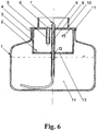
- the lighting device employing liquid fuel comprises an at least essentially cylindrical container 1, which is suitable for receiving and storage of each liquid fuel 14, as well as a burner 7, which is functioning as a lid and is suitable for tightly sealing of said container 1.
- the container 1 is on its end area, which is faced away from the base, furnished with a narrowed neck 4, in the area of which said burner 7 is arranged.
- the burner 7 includes a wick 8, the first end portion of which is located in the interior of the container 1 in such a way that it is capable to absorb liquid fuel 14, while its second end portion passes through the mentioned burner 7 and protrudes out of the container 1.
- the liquid fuel in this particular embodiment a liquid paraffin, is by means of the wick 8 due to capillary effect transported from the interior of the container 1 towards the external second end portion of the wick, which in the area of the burner 7 protrudes outwardly from the container 1.
- said burner 7 comprises an additional opening 6 which serves for aeration of the interior of said container 1 and herewith also for equalising of the air pressure inside of the container 1. Otherwise, during the regular use the air pressure inside of the container 1 would change, since the fuel 14 is burning and consequently, quantity of the fuel 14 inside the container 1 is gradually changed.
- the burner 7 is designed as a hollow lid, which comprises a reservoir 2 for those fuel 14, which is eventually leaked from the interior of the container 1, wherein said reservoir 2 is regularly located above the highest allowed level of the fuel 14 in the container 1, and wherein said burner 7 with the reservoir 2 is adjusted to close and seal said container 1 in the area of its neck 4, as well as to receive those fuel 14, which is leaked from container 1, when the lighting device is tipped over.
- Said burner 7 is on the external surface of the container 1 furnished with an outwardly protruding protective tubular rib 10, which is designed as a circumferentially continuous ring, which extends around the wick 8 and at a distance apart from it, and which is intended for preventing oral contact with the section of the wick 8 which is located outside of the container 1.
- the reservoir 2 of the burner 7 comprises a top wall 15, which is located outside of the container 1 and on the external surface of which said protective tubular rib 10 is arranged, a bottom wall 13, which is located inside of the container 1, as well as a side wall 3, which is located between said bottom wall 13 and top wall 15.
- a tube 9 with a wick 8 inserted there-through is integrated within said reservoir 2 and passes in approximately central arrangement through the top wall 15 and the bottom wall 13, and is sealed either just in the area of the top wall 15 or both in the area of said top wall 15 and the bottom wall 13 of the reservoir 2.
- An aeration opening 6 in the top wall 15 of the reservoir 2 is arranged at a distance apart from the said centrally aligned tube 9 comprising said wick 8.
- An aerating tube 5 is connected to said aeration opening 6, so that the aeration tube 5 enables the air to flow from the exterior of the container 1 towards its interior, or vice versa, and extends towards the bottom wall 13, where it is ended at a sufficient distance apart from the bottom wall 13, whereas the bottom wall 13 of the reservoir 2 is furnished with a further opening 12, which allows the fuel 14 to flow from the interior of the container 1 into the reservoir 2, or vice versa.
- said opening 12 in the bottom wall 13 of the reservoir 2 is arranged adjacent to the circumferential wall 3 of the reservoir 2 and with respect to said centrally arranged tube 9 and the wick 8 inserted there-through oppositely to the aerating opening 6 with belonging tube 5.
- said opening 12 in the bottom wall 13 of the reservoir 2 is arranged coaxially with the tube 9 in such way that the tube 9 passes through the opening 12 by maintaining sufficient gap therebetween.
- the tube 9 together with said which wick 8 inserted there-through is preferably available a metallic tube.
- said tube 9 can generally consist of any other non-flammable non-metallic material, especially for example of ceramics.
- the top wall 15, side wall 3 and the bottom wall 13 of the reservoir 2 preferably consist of synthetic material, but can also be manufactured of any other material suitable for this purpose.
- the level of fuel 14 within the container 1 before and during regular use of the lighting device should always be below the bottom wall 13 of the reservoir 2, which must be established during the first filling of fuel 14 by the manufacturer, and also by every subsequent filling by each user.
- the air is enabled to enter the interior of the container 1 through the openings 6 and 12, which allows fuel 14 to be transported along the wick 8 towards the burner 7.
- the opening 12 in the bottom wall 13 is closed by the fuel 14, and the air is prevented from flowing into container 1.
- the fuel 14, which leaks outside of the container 1, is temporarily stored inside the reservoir 2 and can flow back into the container 1 as soon as the lighting device is returned into its operational position, i.e. its correct position of regular use.
Landscapes
- Engineering & Computer Science (AREA)
- General Engineering & Computer Science (AREA)
- Chemical & Material Sciences (AREA)
- Combustion & Propulsion (AREA)
- Non-Portable Lighting Devices Or Systems Thereof (AREA)
- Feeding And Controlling Fuel (AREA)
Claims (9)
- Beleuchtungsvorrichtung, die flüssigen Brennstoff verwendet, wobei die Vorrichtung mindestens einen Behälter (1), der geeignet ist, einen flüssigen Brennstoff (14) aufzunehmen und zu speichern, sowie einen Brenner (7) umfasst, der auch als Deckel dient und geeignet ist, den Behälter (1) dicht zu verschließen, und der einen Docht (8) umfasst, dessen erster Endabschnitt innerhalb des Behälters (1) so angeordnet ist, dass er den flüssigen Brennstoff (14) aufnehmen kann, während dessen zweiter Endabschnitt aus dem Behälter heraussteht (1) und durch den Brenner (7) geführt ist, wobei der Brenner (7) mit einem Rohr (9) versehen ist, durch das der Docht (8) eingeführt wird, um sich vom Inneren des Behälters (1) zu dessen Außenseite hin zu erstrecken, sowie mit einer zusätzlichen Öffnung (6) zum Belüften des Inneren des Behälters (1) und damit zum Ausgleichen des Luftdrucks innerhalb des Behälters (1) durch Änderungen der darin enthaltenen Brennstoffmenge (14),
wobei der Behälter (1) einen Hals (4) hat, in dessen Bereich der Brenner (7) angeordnet ist, der als hohler Deckel konzipiert ist und einen Sammelbehälter (2) zum Speichern von eventuell aus dem Inneren des Behälters (1) austretendem Brennstoff (14) umfasst, wobei der Sammelbehälter (2) über dem höchstzulässigen Füllstand des Brennstoffs (14) innerhalb des Behälters (1) angeordnet ist, und wobei der mit dem Sammelbehälter (2) versehene Brenner (7) sowohl zum Verschließen und Abdichten des Behälters (1) im Bereich seines Halses (4) als auch zur Aufnahme des Brennstoffs (14) geeignet ist, der aus dem Behälter (1) austreten könnte, wenn die Laterne umkippen würde,
und wobei der Brenner (7) ferner an seiner Außenfläche außerhalb des Behälters (1) mit einer nach außen vorstehenden röhrenförmigen Schutzrippe (10) versehen ist, die als durchgehender Ring ausgebildet ist, der sich um den Docht (8) herum und in einem bestimmten Abstand davon erstreckt und dazu bestimmt ist, Mundkontakt mit dem zweiten Endabschnitt des Dochtes (8) zu verhindern, der sich außerhalb des Behälters (1) befindet, und wobei der Sammelbehälter (2) des Brenners (7) eine obere Wand (15), die sich außerhalb des Behälters (1) befindet und an deren Außenfläche der genannte röhrenförmige Schutzrand (10) angeordnet ist, eine Bodenwand (13), die sich im Behälter (1) befindet, sowie eine Seitenwand (3) umfasst, die zwischen der Bodenwand (13) und der oberen Wand (15) angeordnet ist, und ferner ein Rohr (9) vorgesehen ist, das durch die obere Wand (15) und die Bodenwand (13) des Sammelbehälters (2) geführt ist, in das der Docht (8) eingeführt ist und das im Bereich der Durchführung durch die obere Wand (15) zur Bodenwand (13) hin zumindest annähernd mittig ausgerichtet und abgedichtet ist,
und bei dem die Bodenwand (13) des Sammelbehälters (2) mit einer weiteren Öffnung (12) versehen ist, die dazu vorgesehen ist, dem Brennstoff (14) das Fließen vom Inneren des Behälters (1) in den Sammelbehälter (2) oder umgekehrt zu ermöglichen, wobei der Brennstofffüllstand (14) immer, und zwar sowohl während der normalen Nutzung der Beleuchtungsvorrichtung als auch vorher, unter der Bodenwand (13) des Sammelbehälters (2) gehalten wird, dadurch gekennzeichnet, dass die Belüftungsöffnung (6) in der oberen Wand (15) des Sammelbehälters (2) in einem Abstand von dem mittig angeordneten Rohr (9), das einen Docht (8) umfasst, angeordnet ist, und gleichzeitig ein Belüftungsrohr (5) mit der Belüftungsöffnung (6) verbunden und geeignet ist, die Luft von außerhalb des Behälters (1) in dessen Innenraum oder umgekehrt strömen zu lassen, wobei das Belüftungsrohr (5) in Richtung der Bodenwand (13) vorsteht, aber in einem ausreichenden Abstand von der Bodenwand (13) endet. - Beleuchtungsvorrichtung nach Anspruch 1, dadurch gekennzeichnet, dass das Rohr (9) sowohl im Bereich seiner Durchführung durch die obere Wand (15) zur Bodenwand (13) als auch im Bereich seiner Durchführung durch die Bodenwand (13) zur oberen Wand (15) des Sammelbehälters (2) hin abgedichtet ist.
- Beleuchtungsvorrichtung nach Anspruch 1 oder 2, dadurch gekennzeichnet, dass die Öffnung (12) in der Bodenwand (13) des Sammelbehälters (2) koaxial zu dem Rohr (9) in der Weise angeordnet ist, dass das Rohr (9) durch die Öffnung (12) mit ausreichendem Abstand dazwischen geführt ist.
- Beleuchtungsvorrichtung nach Anspruch 1 oder 2, dadurch gekennzeichnet, dass die erwähnte Öffnung (12) in der Bodenwand (3) des Sammelbehälters (2) nahe der Seitenwand (3) des Sammelbehälters (2) angeordnet ist.
- Beleuchtungsvorrichtung nach Anspruch 4, dadurch gekennzeichnet, dass die Öffnung (12) in der Bodenwand (3) des Sammelbehälters (2) in Bezug auf das mittig angeordnete Rohr (9), das den Docht (8) umfasst, auf der entgegengesetzten Seite der Belüftungsöffnung (6) mit dem zugehörigen Rohr (5) angeordnet ist.
- Beleuchtungsvorrichtung nach einem der Ansprüche 1 bis 5, dadurch gekennzeichnet, dass das Rohr (9), das geeignet ist, den Docht (8) aufzunehmen, aus Metall besteht.
- Beleuchtungsvorrichtung nach einem der Ansprüche 1 bis 5, dadurch gekennzeichnet, dass das Rohr (9), das geeignet ist, den Docht (8) aufzunehmen, aus einem nicht brennbaren, nicht-metallischen Material besteht.
- Beleuchtungsvorrichtung nach Anspruch 7, dadurch gekennzeichnet, dass das Rohr (9), das geeignet ist, den Docht (8) aufzunehmen, aus keramischem Material besteht.
- Beleuchtungsvorrichtung nach einem der vorstehenden Ansprüche, dadurch gekennzeichnet, dass die obere Wand (15), die Seitenwand (3) und die Bodenwand (13) des Sammelbehälters (2) aus synthetischem Material bestehen.
Priority Applications (2)
| Application Number | Priority Date | Filing Date | Title |
|---|---|---|---|
| HRP20200834TT HRP20200834T1 (hr) | 2017-01-03 | 2017-08-17 | Rasvjetni uređaj koji koristi tekuće gorivo |
| PL17800630T PL3559548T3 (pl) | 2017-01-03 | 2017-08-17 | Urządzenie oświetleniowe wykorzystujące ciekłe paliwo |
Applications Claiming Priority (4)
| Application Number | Priority Date | Filing Date | Title |
|---|---|---|---|
| SI201700003A SI25357A (sl) | 2017-01-03 | 2017-01-03 | Varnostni gorilnik za dekorativne oljne svetilke |
| SI201700142A SI25356A (sl) | 2017-01-03 | 2017-05-23 | Svetilka na tekoče gorivo |
| SI201700193A SI25456B (sl) | 2017-01-03 | 2017-06-27 | Svetilka na tekoče gorivo |
| PCT/SI2017/000020 WO2018128588A1 (en) | 2017-01-03 | 2017-08-17 | Lighting device employing liquid fuel |
Publications (2)
| Publication Number | Publication Date |
|---|---|
| EP3559548A1 EP3559548A1 (de) | 2019-10-30 |
| EP3559548B1 true EP3559548B1 (de) | 2020-03-18 |
Family
ID=60382578
Family Applications (1)
| Application Number | Title | Priority Date | Filing Date |
|---|---|---|---|
| EP17800630.0A Active EP3559548B1 (de) | 2017-01-03 | 2017-08-17 | Beleuchtungsvorrichtung mit flüssigem brennstoff |
Country Status (5)
| Country | Link |
|---|---|
| EP (1) | EP3559548B1 (de) |
| DK (1) | DK3559548T3 (de) |
| PL (1) | PL3559548T3 (de) |
| SI (1) | SI25456B (de) |
| WO (1) | WO2018128588A1 (de) |
Family Cites Families (3)
| Publication number | Priority date | Publication date | Assignee | Title |
|---|---|---|---|---|
| GB189414924A (en) * | 1894-08-03 | 1895-06-08 | William Perkins | Improvements in Oil Lamps. |
| DE102008028401A1 (de) * | 2008-06-17 | 2009-12-24 | Auerhahn Bestecke Gmbh | Lichtquelle |
| DE102008063267A1 (de) * | 2008-12-28 | 2010-07-08 | Ovibell Pflanzen, Deko Und Freizeit Gmbh & Co. Kg | Öllampe |
-
2017
- 2017-06-27 SI SI201700193A patent/SI25456B/sl active Search and Examination
- 2017-08-17 EP EP17800630.0A patent/EP3559548B1/de active Active
- 2017-08-17 DK DK17800630.0T patent/DK3559548T3/da active
- 2017-08-17 PL PL17800630T patent/PL3559548T3/pl unknown
- 2017-08-17 WO PCT/SI2017/000020 patent/WO2018128588A1/en not_active Ceased
Non-Patent Citations (1)
| Title |
|---|
| None * |
Also Published As
| Publication number | Publication date |
|---|---|
| EP3559548A1 (de) | 2019-10-30 |
| SI25456B (sl) | 2020-07-31 |
| SI25456A (sl) | 2018-12-31 |
| WO2018128588A1 (en) | 2018-07-12 |
| DK3559548T3 (da) | 2020-06-22 |
| PL3559548T3 (pl) | 2020-08-10 |
Similar Documents
| Publication | Publication Date | Title |
|---|---|---|
| ATE536191T1 (de) | Nachfüllvorrichtung für ein flüchtiges material | |
| US20070290065A1 (en) | Volatile Material Dispensing Apparatus | |
| US8678246B2 (en) | Cartridge and piston with ventilation device | |
| US10808926B2 (en) | Fire display device | |
| WO2008066384A3 (en) | Air deodorizer and pump | |
| JP2009501104A (ja) | タンク用補給管 | |
| JP2020065533A5 (ja) | 霧化ユニット、及び非燃焼式吸引器 | |
| CO4780039A1 (es) | Contenedor cerrado que contiene un liquido | |
| AR017862A1 (es) | Recipiente que incluye un aplicador y un cuerpo que forma un tanque, apto para contener un producto fluido y una pieza antiperdida para dicho recipiente | |
| EP3559548B1 (de) | Beleuchtungsvorrichtung mit flüssigem brennstoff | |
| US10070665B2 (en) | Extinguisher for a smoking article | |
| US20080142613A1 (en) | Volatile Liquid Dissemination Apparatus | |
| JP5712115B2 (ja) | 詰め替え容器 | |
| ITBS20090140A1 (it) | Dispositivo di erogazione di una sostanza | |
| ITPI20070136A1 (it) | Sistema per la chiusura a tenuta di contenitori di profumazione per ambienti | |
| BRPI0412594A (pt) | sistema de refil para recipientes | |
| CN101468733A (zh) | 防止置于容器中的液体或糊状介质污染的漂浮装置 | |
| ES2797200T3 (es) | Dispositivo de iluminación que emplea combustible líquido | |
| EP3643966B1 (de) | Geschützte verbrennungsvorrichtung | |
| JP2018034805A (ja) | エアゾール定量バルブ | |
| JP2008512154A (ja) | 揮発性物質放出装置 | |
| SI25356A (sl) | Svetilka na tekoče gorivo | |
| TWI522575B (zh) | To prevent the accumulation of oil and gas combustion device | |
| JP5184281B2 (ja) | 詰替容器 | |
| US805741A (en) | Filling and closing funnel for liquid. |
Legal Events
| Date | Code | Title | Description |
|---|---|---|---|
| STAA | Information on the status of an ep patent application or granted ep patent |
Free format text: STATUS: UNKNOWN |
|
| STAA | Information on the status of an ep patent application or granted ep patent |
Free format text: STATUS: THE INTERNATIONAL PUBLICATION HAS BEEN MADE |
|
| PUAI | Public reference made under article 153(3) epc to a published international application that has entered the european phase |
Free format text: ORIGINAL CODE: 0009012 |
|
| STAA | Information on the status of an ep patent application or granted ep patent |
Free format text: STATUS: REQUEST FOR EXAMINATION WAS MADE |
|
| 17P | Request for examination filed |
Effective date: 20180724 |
|
| AK | Designated contracting states |
Kind code of ref document: A1 Designated state(s): AL AT BE BG CH CY CZ DE DK EE ES FI FR GB GR HR HU IE IS IT LI LT LU LV MC MK MT NL NO PL PT RO RS SE SI SK SM TR |
|
| AX | Request for extension of the european patent |
Extension state: BA ME |
|
| GRAJ | Information related to disapproval of communication of intention to grant by the applicant or resumption of examination proceedings by the epo deleted |
Free format text: ORIGINAL CODE: EPIDOSDIGR1 |
|
| STAA | Information on the status of an ep patent application or granted ep patent |
Free format text: STATUS: GRANT OF PATENT IS INTENDED |
|
| GRAP | Despatch of communication of intention to grant a patent |
Free format text: ORIGINAL CODE: EPIDOSNIGR1 |
|
| DAV | Request for validation of the european patent (deleted) | ||
| DAX | Request for extension of the european patent (deleted) | ||
| GRAS | Grant fee paid |
Free format text: ORIGINAL CODE: EPIDOSNIGR3 |
|
| INTG | Intention to grant announced |
Effective date: 20191126 |
|
| GRAA | (expected) grant |
Free format text: ORIGINAL CODE: 0009210 |
|
| STAA | Information on the status of an ep patent application or granted ep patent |
Free format text: STATUS: THE PATENT HAS BEEN GRANTED |
|
| AK | Designated contracting states |
Kind code of ref document: B1 Designated state(s): AL AT BE BG CH CY CZ DE DK EE ES FI FR GB GR HR HU IE IS IT LI LT LU LV MC MK MT NL NO PL PT RO RS SE SI SK SM TR |
|
| REG | Reference to a national code |
Ref country code: GB Ref legal event code: FG4D |
|
| REG | Reference to a national code |
Ref country code: AT Ref legal event code: REF Ref document number: 1246314 Country of ref document: AT Kind code of ref document: T Effective date: 20200415 Ref country code: IE Ref legal event code: FG4D |
|
| REG | Reference to a national code |
Ref country code: DE Ref legal event code: R096 Ref document number: 602017013386 Country of ref document: DE |
|
| REG | Reference to a national code |
Ref country code: CH Ref legal event code: NV Representative=s name: OFFICE ERNEST T. FREYLINGER S.A., CH |
|
| REG | Reference to a national code |
Ref country code: NL Ref legal event code: FP |
|
| REG | Reference to a national code |
Ref country code: HR Ref legal event code: TUEP Ref document number: P20200834T Country of ref document: HR |
|
| REG | Reference to a national code |
Ref country code: SE Ref legal event code: TRGR |
|
| REG | Reference to a national code |
Ref country code: DK Ref legal event code: T3 Effective date: 20200615 Ref country code: FI Ref legal event code: FGE |
|
| PG25 | Lapsed in a contracting state [announced via postgrant information from national office to epo] |
Ref country code: RS Free format text: LAPSE BECAUSE OF FAILURE TO SUBMIT A TRANSLATION OF THE DESCRIPTION OR TO PAY THE FEE WITHIN THE PRESCRIBED TIME-LIMIT Effective date: 20200318 |
|
| REG | Reference to a national code |
Ref country code: HR Ref legal event code: T1PR Ref document number: P20200834 Country of ref document: HR |
|
| REG | Reference to a national code |
Ref country code: NO Ref legal event code: T2 Effective date: 20200318 |
|
| PG25 | Lapsed in a contracting state [announced via postgrant information from national office to epo] |
Ref country code: GR Free format text: LAPSE BECAUSE OF FAILURE TO SUBMIT A TRANSLATION OF THE DESCRIPTION OR TO PAY THE FEE WITHIN THE PRESCRIBED TIME-LIMIT Effective date: 20200619 Ref country code: LV Free format text: LAPSE BECAUSE OF FAILURE TO SUBMIT A TRANSLATION OF THE DESCRIPTION OR TO PAY THE FEE WITHIN THE PRESCRIBED TIME-LIMIT Effective date: 20200318 Ref country code: BG Free format text: LAPSE BECAUSE OF FAILURE TO SUBMIT A TRANSLATION OF THE DESCRIPTION OR TO PAY THE FEE WITHIN THE PRESCRIBED TIME-LIMIT Effective date: 20200618 |
|
| REG | Reference to a national code |
Ref country code: LT Ref legal event code: MG4D |
|
| REG | Reference to a national code |
Ref country code: HR Ref legal event code: ODRP Ref document number: P20200834 Country of ref document: HR Payment date: 20200724 Year of fee payment: 4 |
|
| PG25 | Lapsed in a contracting state [announced via postgrant information from national office to epo] |
Ref country code: PT Free format text: LAPSE BECAUSE OF FAILURE TO SUBMIT A TRANSLATION OF THE DESCRIPTION OR TO PAY THE FEE WITHIN THE PRESCRIBED TIME-LIMIT Effective date: 20200812 Ref country code: RO Free format text: LAPSE BECAUSE OF FAILURE TO SUBMIT A TRANSLATION OF THE DESCRIPTION OR TO PAY THE FEE WITHIN THE PRESCRIBED TIME-LIMIT Effective date: 20200318 Ref country code: CZ Free format text: LAPSE BECAUSE OF FAILURE TO SUBMIT A TRANSLATION OF THE DESCRIPTION OR TO PAY THE FEE WITHIN THE PRESCRIBED TIME-LIMIT Effective date: 20200318 Ref country code: IS Free format text: LAPSE BECAUSE OF FAILURE TO SUBMIT A TRANSLATION OF THE DESCRIPTION OR TO PAY THE FEE WITHIN THE PRESCRIBED TIME-LIMIT Effective date: 20200718 Ref country code: SK Free format text: LAPSE BECAUSE OF FAILURE TO SUBMIT A TRANSLATION OF THE DESCRIPTION OR TO PAY THE FEE WITHIN THE PRESCRIBED TIME-LIMIT Effective date: 20200318 Ref country code: LT Free format text: LAPSE BECAUSE OF FAILURE TO SUBMIT A TRANSLATION OF THE DESCRIPTION OR TO PAY THE FEE WITHIN THE PRESCRIBED TIME-LIMIT Effective date: 20200318 Ref country code: SM Free format text: LAPSE BECAUSE OF FAILURE TO SUBMIT A TRANSLATION OF THE DESCRIPTION OR TO PAY THE FEE WITHIN THE PRESCRIBED TIME-LIMIT Effective date: 20200318 Ref country code: EE Free format text: LAPSE BECAUSE OF FAILURE TO SUBMIT A TRANSLATION OF THE DESCRIPTION OR TO PAY THE FEE WITHIN THE PRESCRIBED TIME-LIMIT Effective date: 20200318 |
|
| REG | Reference to a national code |
Ref country code: ES Ref legal event code: FG2A Ref document number: 2797200 Country of ref document: ES Kind code of ref document: T3 Effective date: 20201201 |
|
| REG | Reference to a national code |
Ref country code: DE Ref legal event code: R097 Ref document number: 602017013386 Country of ref document: DE |
|
| PLBE | No opposition filed within time limit |
Free format text: ORIGINAL CODE: 0009261 |
|
| STAA | Information on the status of an ep patent application or granted ep patent |
Free format text: STATUS: NO OPPOSITION FILED WITHIN TIME LIMIT |
|
| 26N | No opposition filed |
Effective date: 20201221 |
|
| PG25 | Lapsed in a contracting state [announced via postgrant information from national office to epo] |
Ref country code: MC Free format text: LAPSE BECAUSE OF FAILURE TO SUBMIT A TRANSLATION OF THE DESCRIPTION OR TO PAY THE FEE WITHIN THE PRESCRIBED TIME-LIMIT Effective date: 20200318 |
|
| REG | Reference to a national code |
Ref country code: HR Ref legal event code: ODRP Ref document number: P20200834 Country of ref document: HR Payment date: 20210715 Year of fee payment: 5 |
|
| PG25 | Lapsed in a contracting state [announced via postgrant information from national office to epo] |
Ref country code: IE Free format text: LAPSE BECAUSE OF NON-PAYMENT OF DUE FEES Effective date: 20200817 |
|
| PG25 | Lapsed in a contracting state [announced via postgrant information from national office to epo] |
Ref country code: TR Free format text: LAPSE BECAUSE OF FAILURE TO SUBMIT A TRANSLATION OF THE DESCRIPTION OR TO PAY THE FEE WITHIN THE PRESCRIBED TIME-LIMIT Effective date: 20200318 Ref country code: MT Free format text: LAPSE BECAUSE OF FAILURE TO SUBMIT A TRANSLATION OF THE DESCRIPTION OR TO PAY THE FEE WITHIN THE PRESCRIBED TIME-LIMIT Effective date: 20200318 Ref country code: CY Free format text: LAPSE BECAUSE OF FAILURE TO SUBMIT A TRANSLATION OF THE DESCRIPTION OR TO PAY THE FEE WITHIN THE PRESCRIBED TIME-LIMIT Effective date: 20200318 |
|
| PG25 | Lapsed in a contracting state [announced via postgrant information from national office to epo] |
Ref country code: MK Free format text: LAPSE BECAUSE OF FAILURE TO SUBMIT A TRANSLATION OF THE DESCRIPTION OR TO PAY THE FEE WITHIN THE PRESCRIBED TIME-LIMIT Effective date: 20200318 Ref country code: AL Free format text: LAPSE BECAUSE OF FAILURE TO SUBMIT A TRANSLATION OF THE DESCRIPTION OR TO PAY THE FEE WITHIN THE PRESCRIBED TIME-LIMIT Effective date: 20200318 |
|
| REG | Reference to a national code |
Ref country code: HR Ref legal event code: ODRP Ref document number: P20200834 Country of ref document: HR Payment date: 20220718 Year of fee payment: 6 |
|
| REG | Reference to a national code |
Ref country code: HR Ref legal event code: ODRP Ref document number: P20200834 Country of ref document: HR Payment date: 20230717 Year of fee payment: 7 |
|
| PG25 | Lapsed in a contracting state [announced via postgrant information from national office to epo] |
Ref country code: SI Free format text: LAPSE BECAUSE OF FAILURE TO SUBMIT A TRANSLATION OF THE DESCRIPTION OR TO PAY THE FEE WITHIN THE PRESCRIBED TIME-LIMIT Effective date: 20200318 |
|
| REG | Reference to a national code |
Ref country code: HR Ref legal event code: ODRP Ref document number: P20200834 Country of ref document: HR Payment date: 20240723 Year of fee payment: 8 |
|
| REG | Reference to a national code |
Ref country code: AT Ref legal event code: UEP Ref document number: 1246314 Country of ref document: AT Kind code of ref document: T Effective date: 20200318 |
|
| PGFP | Annual fee paid to national office [announced via postgrant information from national office to epo] |
Ref country code: NL Payment date: 20250724 Year of fee payment: 9 Ref country code: LU Payment date: 20250724 Year of fee payment: 9 |
|
| REG | Reference to a national code |
Ref country code: HR Ref legal event code: ODRP Ref document number: P20200834 Country of ref document: HR Payment date: 20250716 Year of fee payment: 9 |
|
| PGFP | Annual fee paid to national office [announced via postgrant information from national office to epo] |
Ref country code: ES Payment date: 20250908 Year of fee payment: 9 Ref country code: FI Payment date: 20250804 Year of fee payment: 9 |
|
| PGFP | Annual fee paid to national office [announced via postgrant information from national office to epo] |
Ref country code: DK Payment date: 20250826 Year of fee payment: 9 Ref country code: DE Payment date: 20250723 Year of fee payment: 9 |
|
| PGFP | Annual fee paid to national office [announced via postgrant information from national office to epo] |
Ref country code: NO Payment date: 20250804 Year of fee payment: 9 |
|
| PGFP | Annual fee paid to national office [announced via postgrant information from national office to epo] |
Ref country code: PL Payment date: 20250722 Year of fee payment: 9 Ref country code: IT Payment date: 20250717 Year of fee payment: 9 |
|
| PGFP | Annual fee paid to national office [announced via postgrant information from national office to epo] |
Ref country code: BE Payment date: 20250723 Year of fee payment: 9 Ref country code: GB Payment date: 20250723 Year of fee payment: 9 |
|
| PGFP | Annual fee paid to national office [announced via postgrant information from national office to epo] |
Ref country code: HR Payment date: 20250716 Year of fee payment: 9 |
|
| PGFP | Annual fee paid to national office [announced via postgrant information from national office to epo] |
Ref country code: AT Payment date: 20250808 Year of fee payment: 9 Ref country code: FR Payment date: 20250723 Year of fee payment: 9 |
|
| PGFP | Annual fee paid to national office [announced via postgrant information from national office to epo] |
Ref country code: CH Payment date: 20250901 Year of fee payment: 9 Ref country code: SE Payment date: 20250818 Year of fee payment: 9 |