EP3559429B1 - Ventil - Google Patents
Ventil Download PDFInfo
- Publication number
- EP3559429B1 EP3559429B1 EP17821864.0A EP17821864A EP3559429B1 EP 3559429 B1 EP3559429 B1 EP 3559429B1 EP 17821864 A EP17821864 A EP 17821864A EP 3559429 B1 EP3559429 B1 EP 3559429B1
- Authority
- EP
- European Patent Office
- Prior art keywords
- seal
- housing part
- piston
- housing
- valve according
- Prior art date
- Legal status (The legal status is an assumption and is not a legal conclusion. Google has not performed a legal analysis and makes no representation as to the accuracy of the status listed.)
- Active
Links
Images


Classifications
-
- F—MECHANICAL ENGINEERING; LIGHTING; HEATING; WEAPONS; BLASTING
- F16—ENGINEERING ELEMENTS AND UNITS; GENERAL MEASURES FOR PRODUCING AND MAINTAINING EFFECTIVE FUNCTIONING OF MACHINES OR INSTALLATIONS; THERMAL INSULATION IN GENERAL
- F16K—VALVES; TAPS; COCKS; ACTUATING-FLOATS; DEVICES FOR VENTING OR AERATING
- F16K39/00—Devices for relieving the pressure on the sealing faces
- F16K39/02—Devices for relieving the pressure on the sealing faces for lift valves
- F16K39/024—Devices for relieving the pressure on the sealing faces for lift valves using an auxiliary valve on the main valve
-
- F—MECHANICAL ENGINEERING; LIGHTING; HEATING; WEAPONS; BLASTING
- F01—MACHINES OR ENGINES IN GENERAL; ENGINE PLANTS IN GENERAL; STEAM ENGINES
- F01D—NON-POSITIVE DISPLACEMENT MACHINES OR ENGINES, e.g. STEAM TURBINES
- F01D17/00—Regulating or controlling by varying flow
- F01D17/10—Final actuators
- F01D17/105—Final actuators by passing part of the fluid
-
- F—MECHANICAL ENGINEERING; LIGHTING; HEATING; WEAPONS; BLASTING
- F02—COMBUSTION ENGINES; HOT-GAS OR COMBUSTION-PRODUCT ENGINE PLANTS
- F02B—INTERNAL-COMBUSTION PISTON ENGINES; COMBUSTION ENGINES IN GENERAL
- F02B37/00—Engines characterised by provision of pumps driven at least for part of the time by exhaust
- F02B37/12—Control of the pumps
- F02B37/16—Control of the pumps by bypassing charging air
-
- F—MECHANICAL ENGINEERING; LIGHTING; HEATING; WEAPONS; BLASTING
- F02—COMBUSTION ENGINES; HOT-GAS OR COMBUSTION-PRODUCT ENGINE PLANTS
- F02B—INTERNAL-COMBUSTION PISTON ENGINES; COMBUSTION ENGINES IN GENERAL
- F02B37/00—Engines characterised by provision of pumps driven at least for part of the time by exhaust
- F02B37/12—Control of the pumps
- F02B37/16—Control of the pumps by bypassing charging air
- F02B37/162—Control of the pumps by bypassing charging air by bypassing, e.g. partially, intake air from pump inlet to pump outlet
-
- F—MECHANICAL ENGINEERING; LIGHTING; HEATING; WEAPONS; BLASTING
- F16—ENGINEERING ELEMENTS AND UNITS; GENERAL MEASURES FOR PRODUCING AND MAINTAINING EFFECTIVE FUNCTIONING OF MACHINES OR INSTALLATIONS; THERMAL INSULATION IN GENERAL
- F16K—VALVES; TAPS; COCKS; ACTUATING-FLOATS; DEVICES FOR VENTING OR AERATING
- F16K1/00—Lift valves or globe valves, i.e. cut-off apparatus with closure members having at least a component of their opening and closing motion perpendicular to the closing faces
- F16K1/32—Details
- F16K1/34—Cutting-off parts, e.g. valve members, seats
- F16K1/46—Attachment of sealing rings
-
- F—MECHANICAL ENGINEERING; LIGHTING; HEATING; WEAPONS; BLASTING
- F16—ENGINEERING ELEMENTS AND UNITS; GENERAL MEASURES FOR PRODUCING AND MAINTAINING EFFECTIVE FUNCTIONING OF MACHINES OR INSTALLATIONS; THERMAL INSULATION IN GENERAL
- F16K—VALVES; TAPS; COCKS; ACTUATING-FLOATS; DEVICES FOR VENTING OR AERATING
- F16K17/00—Safety valves; Equalising valves, e.g. pressure relief valves
- F16K17/20—Excess-flow valves
-
- F—MECHANICAL ENGINEERING; LIGHTING; HEATING; WEAPONS; BLASTING
- F16—ENGINEERING ELEMENTS AND UNITS; GENERAL MEASURES FOR PRODUCING AND MAINTAINING EFFECTIVE FUNCTIONING OF MACHINES OR INSTALLATIONS; THERMAL INSULATION IN GENERAL
- F16K—VALVES; TAPS; COCKS; ACTUATING-FLOATS; DEVICES FOR VENTING OR AERATING
- F16K25/00—Details relating to contact between valve members and seats
- F16K25/005—Particular materials for seats or closure elements
-
- F—MECHANICAL ENGINEERING; LIGHTING; HEATING; WEAPONS; BLASTING
- F16—ENGINEERING ELEMENTS AND UNITS; GENERAL MEASURES FOR PRODUCING AND MAINTAINING EFFECTIVE FUNCTIONING OF MACHINES OR INSTALLATIONS; THERMAL INSULATION IN GENERAL
- F16K—VALVES; TAPS; COCKS; ACTUATING-FLOATS; DEVICES FOR VENTING OR AERATING
- F16K27/00—Construction of housing; Use of materials therefor
- F16K27/02—Construction of housing; Use of materials therefor of lift valves
- F16K27/029—Electromagnetically actuated valves
-
- F—MECHANICAL ENGINEERING; LIGHTING; HEATING; WEAPONS; BLASTING
- F16—ENGINEERING ELEMENTS AND UNITS; GENERAL MEASURES FOR PRODUCING AND MAINTAINING EFFECTIVE FUNCTIONING OF MACHINES OR INSTALLATIONS; THERMAL INSULATION IN GENERAL
- F16K—VALVES; TAPS; COCKS; ACTUATING-FLOATS; DEVICES FOR VENTING OR AERATING
- F16K31/00—Actuating devices; Operating means; Releasing devices
- F16K31/02—Actuating devices; Operating means; Releasing devices electric; magnetic
- F16K31/06—Actuating devices; Operating means; Releasing devices electric; magnetic using a magnet, e.g. diaphragm valves, cutting off by means of a liquid
- F16K31/0644—One-way valve
- F16K31/0655—Lift valves
-
- F—MECHANICAL ENGINEERING; LIGHTING; HEATING; WEAPONS; BLASTING
- F16—ENGINEERING ELEMENTS AND UNITS; GENERAL MEASURES FOR PRODUCING AND MAINTAINING EFFECTIVE FUNCTIONING OF MACHINES OR INSTALLATIONS; THERMAL INSULATION IN GENERAL
- F16K—VALVES; TAPS; COCKS; ACTUATING-FLOATS; DEVICES FOR VENTING OR AERATING
- F16K31/00—Actuating devices; Operating means; Releasing devices
- F16K31/02—Actuating devices; Operating means; Releasing devices electric; magnetic
- F16K31/06—Actuating devices; Operating means; Releasing devices electric; magnetic using a magnet, e.g. diaphragm valves, cutting off by means of a liquid
- F16K31/0686—Braking, pressure equilibration, shock absorbing
-
- F—MECHANICAL ENGINEERING; LIGHTING; HEATING; WEAPONS; BLASTING
- F02—COMBUSTION ENGINES; HOT-GAS OR COMBUSTION-PRODUCT ENGINE PLANTS
- F02B—INTERNAL-COMBUSTION PISTON ENGINES; COMBUSTION ENGINES IN GENERAL
- F02B39/00—Component parts, details, or accessories relating to, driven charging or scavenging pumps, not provided for in groups F02B33/00 - F02B37/00
- F02B39/16—Other safety measures for, or other control of, pumps
- F02B2039/162—Control of pump parameters to improve safety thereof
- F02B2039/166—Control of pump parameters to improve safety thereof the fluid pressure in the pump or exhaust drive being limited
-
- Y—GENERAL TAGGING OF NEW TECHNOLOGICAL DEVELOPMENTS; GENERAL TAGGING OF CROSS-SECTIONAL TECHNOLOGIES SPANNING OVER SEVERAL SECTIONS OF THE IPC; TECHNICAL SUBJECTS COVERED BY FORMER USPC CROSS-REFERENCE ART COLLECTIONS [XRACs] AND DIGESTS
- Y02—TECHNOLOGIES OR APPLICATIONS FOR MITIGATION OR ADAPTATION AGAINST CLIMATE CHANGE
- Y02T—CLIMATE CHANGE MITIGATION TECHNOLOGIES RELATED TO TRANSPORTATION
- Y02T10/00—Road transport of goods or passengers
- Y02T10/10—Internal combustion engine [ICE] based vehicles
- Y02T10/12—Improving ICE efficiencies
Definitions
- the invention relates to a valve according to claim 1.
- valves are used, among other things, as bypass valves on turbochargers in motor vehicles (see for example US 2013/313455 A1 , WO 2014/068765 A1 or WO 2016/041659 A1 ) to open a bypass to the suction side during overrun and are therefore well known.
- rapid opening and closing of the valve is an essential prerequisite.
- closing it is particularly important that the valve closes immediately by placing the piston on a valve seat.
- the valve seat is formed by the housing of the turbocharger, to which the valve is flanged.
- the axially movable piston must be sealed against the housing.
- the invention is therefore based on the object of creating a valve with improved sealing function. At the same time, the valve should be simpler in construction and cost-effective.
- the seal is connected to the second housing part, wherein the seal surrounds a region of the second housing part such that this region forms at least one undercut for the seal.
- an undercut is understood to mean a design of the seal and/or the housing part that does not allow the seal to be removed from its predetermined position by means of a simple translatory or rotary movement, or at least makes it so difficult that the seal can only be removed with damage to the seal.
- the advantage of the valve according to the invention is that the at least one undercut reliably holds the seal in its position over its service life. Additional fastening elements are not necessary for this. This makes it possible to produce a particularly cost-effective valve.
- undercuts can be produced in small dimensions, so that the valve does not require any additional installation space in the area of the second housing part.
- the undercut comprises at least one area, whereby this area is formed by a radius.
- the end of the second housing part facing away from the housing is angled.
- the angles can be between 5° and 180°, preferably 90°. It has been shown that the security against loosening increases with increasing angle.
- the security against the seal coming loose can also be increased by having several areas formed by radii form the undercut.
- the undercut comprises at least one region which has at least one recess, preferably 2 to 12 recesses and in particular 4 to 8 recesses. By filling these recesses, the seal is inseparably connected to the second housing part.
- each of the undercuts described above provides sufficient security against the seal coming loose, it can still be useful to provide a combination of areas formed by radii and recesses, particularly if the valve is used under particularly harsh external conditions.
- an advantageous design is to manufacture the seal from a fluororubber (FKM rubber). This material is sufficiently robust and allows reliable operation of the valve even at temperatures of 180 °C.
- the seal can be vulcanized onto the second housing part.
- the service life of the seal is increased in that the seal has a sealing lip that acts in the axial direction. This alignment of the sealing effect ensures that the seal only comes into contact with the piston in one position, namely the end position. Permanent contact with the piston, particularly during movement of the piston with the associated friction, is avoided.
- the second housing part consists of metal, preferably of stainless steel, in particular of a chrome-nickel steel.
- the second housing part can also be formed with low wall thicknesses in the range of 0.3 mm to 3 mm, preferably 0.5 mm to 1 mm, with sufficient dimensional stability.
- the second housing part can be manufactured particularly cost-effectively as a deep-drawn part.
- the shape of the second housing part can be achieved in just one work step without any further processing.
- the piston is made of metal, preferably of stainless steel, in particular a chrome-nickel steel.
- Such a piston can also be produced by deep drawing, whereby the sealing surface for the seal on the second housing part can be formed in one work step.
- the valve according to the invention can therefore be manufactured particularly cost-effectively.
- Figure 1 shows the valve, comprising a housing 1 with a one-piece molded-on socket 2 for electrically connecting the valve.
- the housing 1 also has a molded-on flange 3 and three holes 3a, via which the housing 1 is flanged to a turbocharger (not shown) in the area of the bypass line 4.
- a second housing part 13 is connected to the flange 3.
- a solenoid 5 with a coil 6 and a metal pin 7 is arranged in the housing 1.
- the metal pin 7 is connected to a pot-shaped piston 8, which has an axially protruding ring-shaped seal 10 on the circumference of its base 9.
- the seal 10 rests on the valve seat 11 to close the bypass line 4 so that no medium can flow from the line 4 into the line 12.
- a spring 7a presses the piston 8 towards the valve seat 11.
- FIG. 2 shows the second housing part 13 with its cylindrical basic shape and the piston 8 with its cylindrical outer surface 14 in the closed position.
- Housing part 13 and piston 8 are deep-drawn parts made of chrome-nickel steel.
- the second housing part 13 has a radially outward-pointing edge 15 at its end facing the housing 1.
- An O-ring acting as a seal 16 is arranged in the housing 1 concentrically to the edge 15.
- the housing 1 has a cylindrical section 17 extending from the solenoid 5 in the direction of the piston 8.
- the second housing part 13 is pressed onto the cylindrical section 17 to such an extent that the edge 15 rests against the housing 1.
- the second housing part 13 has a cylindrical outer surface with two diameters.
- the larger diameter 18 is aligned with the housing 1 and is larger than the cylindrical section 17, while the smaller diameter 19 is selected so that the inside forms the contact surface for the press connection with the section 17.
- the area of the larger diameter 18 serves to decouple the contact surface 15 on the housing 1 and the press connection in the area of the smaller diameter 19.
- the second housing part 13 also has a collar 20 bent by 90° and pointing radially inwards at its end facing away from the housing 1.
- a seal 21 arranged on the second housing part 13 encloses an area of the housing part 13. This area includes part of the cylindrical outer surface 19 and the collar 20.
- the outer surface 19 and the collar 20 form an undercut which prevents the seal 21 from coming loose.
- the seal 21 made of fluororubber consists of a base body 22 which surrounds the aforementioned area on the second housing part 13 and a sealing lip 23 pointing towards the housing.
- the sealing lip 23 interacts with a sealing surface 24 on the piston 8 in the form of an axial seal.
- the piston 8 also has a radially outward-projecting edge at its end facing the housing 1 which rests on the sealing lip 23 when the valve is closed.
- the seal 10 is arranged on the bottom 9 of the piston 8. This is a fluororubber.
- the seal 10 is vulcanized onto the piston 8.
- the bottom 9 has several recesses 24 that are filled by the seal 10. In this way, the seal 10 is permanently connected to the piston 8.
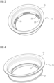
- Figure 3 shows the second housing part 13 without the seal 21.
- the collar 20 has 6 recesses 25, which also have undercuts for the seal 21, since the seal fills the recesses 25.
- Figure 4 shows the second housing part 13 with the seal 21 and the sealing lip 23 aligned with the piston.
Landscapes
- Engineering & Computer Science (AREA)
- General Engineering & Computer Science (AREA)
- Mechanical Engineering (AREA)
- Chemical & Material Sciences (AREA)
- Combustion & Propulsion (AREA)
- Electromagnetism (AREA)
- Physics & Mathematics (AREA)
- Magnetically Actuated Valves (AREA)
- Sealing Devices (AREA)
- Lift Valve (AREA)
- Sealing With Elastic Sealing Lips (AREA)
- Supercharger (AREA)
- Gasket Seals (AREA)
Description
- Gegenstand der Erfindung ist ein Ventil nach Anspruch 1.
- Solche Ventile werden unter anderem als Schubumluftventil am Turbolader in Kraftfahrzeugen eingesetzt (siehe zum Beispiel
US 2013/313455 A1 ,WO 2014/068765 A1 oderWO 2016/041659 A1 ), um im Schubbetrieb einen Bypass zur Saugseite freizugeben und sind somit bekannt. Um ein zu starkes Abbremsen des Turboladers zu verhindern, aber auch ein schnelles Anfahren zu gewährleisten, ist ein schnelles Öffnen und Schließen des Ventils eine wesentliche Voraussetzung. Insbesondere beim Schließen kommt es auf das sofortige Verschließen durch das Anlegen des Kolbens an einen Ventilsitz an. Der Ventilsitz wird vom Gehäuse des Turboladers gebildet, an dem das Ventil angeflanscht wird. Darüber hinaus muss der axial verschiebliche Kolben gegen das Gehäuse abgedichtet sein. Hierzu ist es bekannt, in dem Gehäuse eine V-förmige Dichtung anzuordnen, deren Schenkel jeweils am zweiten Gehäuseteil und an der Mantelfläche des Kolbens anliegen. Diese Dichtung erfordert zudem eine Fixierung im Gehäuseteil, um ein dichtes Anliegen am Kolben zu gewährleisten. Dazu wird die Dichtung durch ein weiteres Bauteil mit dem zweiten Gehäuseteil verpresst. Dies erfordert jedoch zusätzlichen konstruktiven Aufwand, der zu höheren Kosten solcher Ventile führt. - Der Erfindung liegt daher die Aufgabe zugrunde, ein Ventil mit verbesserter Dichtfunktion zu schaffen. Gleichzeitig soll das Ventil einfacher aufgebaut und kostengünstig sein.
- Gelöst wird die Aufgabe dadurch, dass die Dichtung mit dem zweiten Gehäuseteil verbunden ist, wobei die Dichtung einen Bereich des zweiten Gehäuseteils derart umgibt, dass dieser Bereich zumindest einen Hinterschnitt für die Dichtung bildet.
- Das Verbinden der Dichtung mit dem Gehäuseteil, indem die Dichtung einen Bereich des zweiten Gehäuseteils so umgibt, dass ein Hinterschnitt gebildet wird, gewährleistet einen sicheren und zuverlässigen Sitz der Dichtung am Gehäuseteil. Unter einem Hinterschnitt wird dabei eine Ausbildung der Dichtung und/oder des Gehäuseteils verstanden, die ein Entfernen der Dichtung aus ihrer vorbestimmten Position mittels einer einfachen translatorischen oder rotatorischen Bewegung nicht zulässt oder zumindest derart erschwert, dass ein Entfernen der Dichtung nur mit Beschädigungen der Dichtung möglich sind. Der Vorteil des erfindungsgemäßen Ventils besteht darin, dass durch den zumindest einen Hinterschnitt die Dichtung über die Lebensdauer zuverlässig in ihrer Position gehalten wird. Zusätzliche Befestigungselemente sind dazu nicht notwendig. Dadurch lässt sich ein besonders kostengünstiges Ventil herstellen. Des Weiteren lassen sich Hinterschnitte bereits in kleinen Dimensionen erzeugen, so dass das Ventil im Bereich des zweiten Gehäuseteils keinen zusätzlichen Bauraum erfordert.
- In einer einfachen Ausgestaltung umfasst der Hinterschnitt zumindest einen Bereich, wobei dieser Bereich durch einen Radius gebildet ist. Im einfachsten Fall ist das dem Gehäuse abgewandte Ende des zweiten Gehäuseteils abgewinkelt. Die Winkel können hierbei zwischen 5° und 180°, vorzugsweise 90° liegen. Dabei hat sich gezeigt, dass die Sicherheit gegen ein Lösen mit zunehmendem Winkel steigt.
- Die Sicherheit gegen ein Lösen der Dichtung lässt sich auch dadurch erhöhen, dass mehrere durch Radien gebildete Bereiche den Hinterschnitt bilden.
- In einer anderen vorteilhaften Ausgestaltung umfasst der Hinterschnitt zumindest einen Bereich, der zumindest eine Ausnehmung, vorzugsweise 2 bis 12 Ausnehmungen und insbesondere 4 bis 8 Ausnehmungen besitzt. Indem die Dichtung diese Ausnehmungen ausfüllt, ist sie untrennbar mit dem zweiten Gehäuseteil verbunden.
- Obwohl jeder der eben beschrieben Hinterschnitte für sich allein bereits eine ausreichende Sicherheit gegen ein Lösen der Dichtung bietet, kann es dennoch sinnvoll sein, eine Kombination von durch Radien gebildete Bereiche und Ausnehmungen vorzusehen. Insbesondere dann, wenn das Ventil unter besonders rauen äußeren Bedingungen eingesetzt wird.
- Um eine gute Dichtwirkung bei geringem Verschließ über die gesamte Lebensdauer zu erreichen, besteht eine vorteilhafte Ausgestaltung darin, die Dichtung aus einem Fluorkautschuk (FKM-Gummi herzustellen. Dieses Material ist ausreichend robust und erlaubt auch bei Temperaturen von 180 °C einen zuverlässigen Betrieb des Ventils.
- Um eine besonders sichere Verbindung mit dem zweiten Gehäuseteil zu erzielen, kann die Dichtung an dem zweiten Gehäuseteil aufvulkanisiert werden.
- Die Lebensdauer der Dichtung wird gemäß einer weiteren vorteilhaften Ausgestaltung dadurch erhöht, dass die Dichtung eine in axialer Richtung wirkende Dichtlippe besitzt. Durch diese Ausrichtung der Dichtwirkung wird erreicht, dass die Dichtung mit dem Kolben nur in einer Position, nämlich der Endlage, in Kontakt tritt. Ein permanenter Kontakt mit dem Kolben, insbesondere während des Bewegens des Kolbens mit der damit verbundenen Reibung wird vermieden.
- Eine gute Beständigkeit gegenüber verschiedensten durchströmenden Medien und Mediengemischen, vorzugsweise Abgas eines Verbrennungsmotors, wird in einer besonders vorteilhaften Ausgestaltung dadurch erreicht, dass das zweite Gehäuseteil aus Metall, vorzugsweise aus Edelstahl, insbesondere aus einem Chrom-Nickel-Stahl besteht. Zudem lässt sich das zweite Gehäuseteil dadurch auch mit geringen Wandstärken im Bereich von 0,3 mm bis 3 mm, vorzugsweise 0,5 mm bis 1 mm, mit ausreichender Formstabilität ausbilden.
- Das zweite Gehäuseteil lässt sich gemäß einer weiteren vorteilhaften Ausgestaltung besonders kostengünstig als Tiefziehteil herstellen. Die Formgebung des zweiten Gehäuseteils lässt sich in nur einem Arbeitsschritt ohne weitere Bearbeitungen erzielen.
- In gleicher Weise ist es vorteilhaft, wenn der Kolben aus Metall besteht, vorzugsweise aus Edelstahl, insbesondere einem Chrom-Nickel-Stahl. Ein solcher Kolben lässt sich ebenfalls mittels Tiefziehen herstellen, wodurch sich in einem Arbeitsschritt die Dichtfläche für die Dichtung am zweiten Gehäuseteil ausbilden lässt. Das erfindungsgemäße Ventil lässt sich dadurch besonders kostengünstig fertigen.
- Mit der Anordnung einer axial wirkenden Dichtung, die mit dem Kolben nur im geschlossenen Zustand zusammenwirkt, wird erreicht, dass die Berührung von Dichtung und Kolben auf einen Zeitraum beschränkt wird, in der sich der Kolben in Ruhe befindet einschließlich eines Zeitraums unmittelbar bevor der Kolben zur Ruhe kommt. Damit ist gemeint, dass sich Kolben und Dichtung bereits kurz vor der Schließstellung berühren. Mit der letzten Bewegung des Kolbens in die Schließstellung wird die Dichtung so verformt, dass die Dichtflächen gegeneinander vorgespannt sind. Mit der axial wirkenden Dichtung wird daher verhindert, dass die Dichtung während der Bewegung des Kolbens beim Öffnen und Schließen in Kontakt mit dem Kolben ist und einer damit einhergehenden Reibung ausgesetzt ist. Ein reibungsbedingter Verschleiß wird somit verhindert und die Lebensdauer der Dichtung verbessert.
- An einem Ausführungsbeispiel wird die Erfindung näher beschrieben. Es zeigt in
- Fig. 1
- eine Schnittdarstellung des erfindungsgemäßen Ventils,
- Fig. 2
- eine vergrößerte Darstellung des zweiten Gehäuseteils und
- Fig. 3, 4
- eine weitere Ausgestaltung des zweiten Gehäuseteils.
-
Figur 1 zeigt das Ventil, umfassend ein Gehäuse 1 mit einteilig angeformter Buchse 2 zum elektrischen Verbinden des Ventils. Das Gehäuse 1 besitzt weiter einen angeformten Flansch 3 und drei Bohrungen 3a, über die das Gehäuse 1 an einem nicht dargestellten Turbolader im Bereich der Bypassleitung 4 angeflanscht ist. In der gezeigten Einbaulage schließt sich an den Flansch 3 ein zweites Gehäuseteil 13 an. In dem Gehäuse 1 ist ein Solenoid 5 mit einer Spule 6 und einem Metallstift 7 angeordnet. Der Metallstift 7 ist mit einem topfförmigen Kolben 8 verbunden, der am Umfang seines Bodens 9 eine axial abstehende ringförmige Dichtung 10 besitzt. In der gezeigten Schließstellung liegt die Dichtung 10 auf dem Ventilsitz 11 an, um die Bypassleitung 4 zu verschließen, so dass kein Medium von aus der Leitung 4 in die Leitung 12 strömen kann. Eine Feder 7a drückt dabei den Kolben 8 in Richtung Ventilsitz 11. -
Figur 2 zeigt das zweite Gehäuseteil 13 mit seiner zylindrischen Grundform und den Kolben 8 mit seiner zylindrischen Mantelfläche 14 in Schließstellung. Gehäuseteil 13 und Kolben 8 sind Tiefziehteile aus Chrom-Nickel-Stahl. Das zweite Gehäuseteil 13 besitzt an seinem dem Gehäuse 1 zugewandten Ende eine nach radial außen weisenden Kante 15. Konzentrisch zur Kante 15 ist im Gehäuse 1 ein als Dichtung 16 wirkender O-Ring im Gehäuse 1 angeordnet. Das Gehäuse 1 besitzt einen sich vom Solenoid 5 in Richtung Kolben 8 erstreckenden zylindrischen Abschnitt 17. Das zweite Gehäuseteil 13 ist auf den zylindrischen Abschnitt 17 soweit aufgepresst, dass die Kante 15 am Gehäuse 1 anliegt. Für eine definierte Anlagefläche für das Einpressen besitzt das zweite Gehäuseteil 13 eine zylindrische Mantelfläche mit zwei Durchmessern. Der größere Durchmesser 18 ist zum Gehäuse 1 ausgerichtet und ist größer als der zylindrische Abschnitt 17, während der kleinere Durchmesser 19 so gewählt ist, dass die Innenseite die Anlagefläche für die Pressverbindung mit dem Abschnitt 17 bildet. Der Bereich des größeren Durchmessers 18, dient der Entkopplung der Anlagefläche 15 am Gehäuse 1 und der Pressverbindung im Bereich des kleineren Durchmessers 19. - Das zweite Gehäuseteil 13 besitzt weiter an seinem dem Gehäuse 1 abgewandten Ende einen um 90° umgebogenen, nach radial innen weisenden Kragen 20. Eine am zweiten Gehäuseteil 13 angeordnete Dichtung 21 umschließt einen Bereich des Gehäuseteils 13. Dieser Bereich umfasst einen Teil der zylindrischen Mantelfläche 19 und den Kragen 20. Mantelfläche 19 und Kragen 20 bilden einen Hinterschnitt, der ein Lösen der Dichtung 21 verhindert. Die Dichtung 21 aus Fluorkautschuk besteht aus einem Grundkörper 22, der den genannten Bereich am zweiten Gehäuseteil 13 umgibt und einer in Richtung Gehäuse weisenden Dichtlippe 23. Die Dichtlippe 23 wirkt mit einer Dichtfläche 24 am Kolben 8 in Form einer Axialdichtung zusammen. Der Kolben 8 besitzt dazu an seinem dem Gehäuse 1 zugewandten Ende eine nach radial außen abstehende Kante, die im geschlossenen Zustand des Ventils auf der Dichtlippe 23 aufliegt.
- Am Boden 9 des Kolbens 8 ist die Dichtung 10 angeordnet. Es handelt sich hierbei um einen Fluorkautschuk. Die Dichtung 10 ist an den Kolben 8 aufvulkanisiert. Der Boden 9 weist mehrere Ausnehmungen 24 auf, die von der Dichtung 10 ausgefüllt sind. Auf diese Weise ist die Dichtung 10 unlösbar mit dem Kolben 8 verbunden.
-
Figur 3 zeigt das zweite Gehäuseteil 13 ohne die Dichtung 21. Der Kragen 20 besitzt 6 Ausnehmungen 25, welche ebenfalls Hinterschnitte für die Dichtung 21 bilden, da die Dichtung die Ausnehmungen 25 ausfüllt. -
Figur 4 zeigt das zweite Gehäuseteil 13 mit der Dichtung 21 und der zum Kolben ausgerichteten Dichtlippe 23.
Claims (10)
- Ventil mit einem Gehäuse (1), einem in dem Gehäuse angeordneten Solenoid (5),einem von dem Solenoid bewegbaren Stift (7) und einem mit dem Stift verbundenen topfförmigen Kolben (8), der am Umfang seines Bodens eine axial abstehende ringförmige Dichtung (10) besitzt, welche in Schließstellung auf einem Ventilsitz (11) anliegt, wobei ein zweites Gehäuseteil (13) vorgesehen ist welches an dem Gehäuse anliegt und den Kolben teilweise aufnimmt,
undeiner zwischen dem zweiten Gehäuseteil und dem Kolben angeordneten Dichtung (21),dadurch gekennzeichnet, dass die zwischen dem zweiten Gehäuseteil (13) und dem Kolben (8) angeordnete Dichtung (21) mit demzweiten Gehäuseteil (13) verbunden ist, wobei die zwischen dem zweiten Gehäuseteil (13) und dem Kolben (8) angeordnete Dichtung (21) einenBereich des zweiten Gehäuseteils (13) derart umgibt, dass dieser Bereich zumindest einen Hinterschnitt (20, 25) für die zwischen dem zweiten Gehäuseteil (13) und dem Kolben (8) angeordnete Dichtung (21)
bildet. - Ventil nach Anspruch 1, dadurch gekennzeichnet, dass der Hinterschnitt (20) zumindest einen Bereich umfasst, der durch einen Radius gebildet ist.
- Ventil nach Anspruch 1, dadurch gekennzeichnet, dass der Hinterschnitt (25) zumindest einen Bereich umfasst, der zumindest eine Ausnehmung, vorzugsweise 2 bis 12 Ausnehmungen und insbesondere 4 bis 8 Ausnehmungen besitzt.
- Ventil nach zumindest einem der vorhergehenden Ansprüche, dadurch gekennzeichnet, dass die zwischen dem zweiten Gehäuseteil (13) und dem Kolben (8) angeordnete Dichtung (21) aus einem FKM-Gummi besteht.
- Ventil nach zumindest einem der vorhergehenden Ansprüche, dadurch gekennzeichnet, dass die zwischen dem zweiten Gehäuseteil (13) und dem Kolben (8) angeordnete Dichtung (21) an dem zweiten Gehäuseteil (13) aufvulkanisiert ist.
- Ventil nach zumindest einem der vorhergehenden Ansprüche, dadurch gekennzeichnet, dass die zwischen dem zweiten Gehäuseteil (13) und dem Kolben (8) angeordnete Dichtung (21) eine in axialer Richtung wirkende Dichtlippe (23) besitzt.
- Ventil nach zumindest einem der vorhergehenden Ansprüche, dadurch gekennzeichnet, dass das zweite Gehäuseteil (13) aus Metall besteht, vorzugsweise aus Edelstahl, insbesondere ein Chrom-Nickel-Stahl ist.
- Ventil nach zumindest einem der vorhergehenden Ansprüche, dadurch gekennzeichnet, dass das zweite Gehäuseteil (13) ein Tiefziehteil ist.
- Ventil nach Anspruch 8, dadurch gekennzeichnet, dass der Kolben (8) aus Metall besteht, vorzugsweise aus Edelstahl, insbesondere aus einem Chrom-Nickel-Stahl.
- Ventil nach zumindest einem der vorhergehenden Ansprüche, dadurch gekennzeichnet, dass der Kolben (8) ein Tiefziehteil ist.
Applications Claiming Priority (2)
| Application Number | Priority Date | Filing Date | Title |
|---|---|---|---|
| DE102016226106.1A DE102016226106A1 (de) | 2016-12-22 | 2016-12-22 | Ventil |
| PCT/EP2017/082640 WO2018114529A1 (de) | 2016-12-22 | 2017-12-13 | Ventil |
Publications (2)
| Publication Number | Publication Date |
|---|---|
| EP3559429A1 EP3559429A1 (de) | 2019-10-30 |
| EP3559429B1 true EP3559429B1 (de) | 2024-12-04 |
Family
ID=60813836
Family Applications (1)
| Application Number | Title | Priority Date | Filing Date |
|---|---|---|---|
| EP17821864.0A Active EP3559429B1 (de) | 2016-12-22 | 2017-12-13 | Ventil |
Country Status (7)
| Country | Link |
|---|---|
| US (1) | US11168802B2 (de) |
| EP (1) | EP3559429B1 (de) |
| JP (1) | JP7216001B2 (de) |
| KR (1) | KR20190099016A (de) |
| CN (1) | CN110114565A (de) |
| DE (1) | DE102016226106A1 (de) |
| WO (1) | WO2018114529A1 (de) |
Families Citing this family (4)
| Publication number | Priority date | Publication date | Assignee | Title |
|---|---|---|---|---|
| DE102016226098A1 (de) | 2016-12-22 | 2018-06-28 | Continental Automotive Gmbh | Ventil |
| DE102018214458A1 (de) * | 2018-08-27 | 2020-02-27 | Continental Automotive Gmbh | Ventil |
| US20210156484A1 (en) * | 2019-11-25 | 2021-05-27 | Vitesco Technologies USA, LLC | Integrated piston-seal structure for vehicle electronic compressor bypass valve |
| EP4139596B1 (de) * | 2020-04-24 | 2025-06-18 | Pierburg GmbH | Schubumluftventil |
Family Cites Families (22)
| Publication number | Priority date | Publication date | Assignee | Title |
|---|---|---|---|---|
| US4156439A (en) * | 1977-10-11 | 1979-05-29 | The Cessna Aircraft Company | Agriculture chemical spray valve |
| JPS639568A (ja) | 1986-06-30 | 1988-01-16 | Mita Ind Co Ltd | プリンタ装置の安全装置 |
| US6039323A (en) * | 1998-02-11 | 2000-03-21 | Fel-Pro Incorporated | Rubber molded gasket with compression limiter |
| US20030042450A1 (en) | 2001-08-31 | 2003-03-06 | Bircann Raul A. | Force-balanced gas control valve |
| JP2004003541A (ja) | 2002-05-31 | 2004-01-08 | Saginomiya Seisakusho Inc | 弁装置用弁座部材および電磁制御弁 |
| EP2074325B1 (de) * | 2006-10-17 | 2010-01-06 | Selettra S.r.l. | Membranvergaser mit elektromagnetischem stellantrieb |
| US8235394B2 (en) * | 2007-12-06 | 2012-08-07 | Freudenberg-Nok General Partnership | Valve stem seal with gas relief features |
| DE102008031738A1 (de) | 2008-07-04 | 2010-01-07 | Pierburg Gmbh | Schubumluftventil |
| US20120313329A1 (en) | 2011-06-10 | 2012-12-13 | Freudenberg-Nok General Partnership | Vented Dual Lip Seal And Method Of Making |
| US9371749B2 (en) * | 2012-02-08 | 2016-06-21 | Dana Automotive Systems Group, Llc | Hybrid valve stem seal retainer assembly |
| US20130269599A1 (en) * | 2012-04-13 | 2013-10-17 | Taiwan Semiconductor Manufacturing Company, Ltd. | Methods and Apparatus for Continuous Pressure Control Processing |
| DE102012010140A1 (de) * | 2012-05-24 | 2013-11-28 | Eagle Actuator Components Gmbh & Co. Kg | Elektrisches Schubumiuftventil |
| DE102012211575A1 (de) | 2012-07-04 | 2014-01-09 | Robert Bosch Gmbh | Ventil zum Steuern eines gasförmigen Mediums mit kostengünstigem Dichtelement |
| WO2014068765A1 (ja) * | 2012-11-02 | 2014-05-08 | 三菱電機株式会社 | バルブ |
| DE102013220685A1 (de) | 2013-10-14 | 2015-04-16 | Continental Automotive Gmbh | Ventil |
| US9360120B2 (en) | 2013-11-01 | 2016-06-07 | Emerson Process Management Regulator Technologies, Inc. | Valve plug for pressure regulator |
| JP2016008683A (ja) | 2014-06-25 | 2016-01-18 | 浜名湖電装株式会社 | 流体制御弁装置 |
| JP6347444B2 (ja) * | 2014-09-12 | 2018-06-27 | 日立オートモティブシステムズ株式会社 | 電磁弁 |
| DE102014113550B3 (de) * | 2014-09-19 | 2016-03-31 | Pierburg Gmbh | Verstellorgan für ein Schubumluftventil |
| DE102014113540B3 (de) * | 2014-09-19 | 2016-02-04 | Pierburg Gmbh | Schubumluftventil für einen Verdichter eines Verbrennungsmotors |
| DE102014113566B3 (de) | 2014-09-19 | 2016-02-04 | Pierburg Gmbh | Elektromagnetventil für einen Verbrennungsmotor |
| WO2016162968A1 (ja) * | 2015-04-08 | 2016-10-13 | 三菱電機株式会社 | 電磁弁 |
-
2016
- 2016-12-22 DE DE102016226106.1A patent/DE102016226106A1/de not_active Ceased
-
2017
- 2017-12-13 US US16/471,791 patent/US11168802B2/en active Active
- 2017-12-13 WO PCT/EP2017/082640 patent/WO2018114529A1/de not_active Ceased
- 2017-12-13 EP EP17821864.0A patent/EP3559429B1/de active Active
- 2017-12-13 KR KR1020197020964A patent/KR20190099016A/ko not_active Ceased
- 2017-12-13 CN CN201780079597.5A patent/CN110114565A/zh active Pending
- 2017-12-13 JP JP2019534310A patent/JP7216001B2/ja active Active
Also Published As
| Publication number | Publication date |
|---|---|
| KR20190099016A (ko) | 2019-08-23 |
| DE102016226106A1 (de) | 2018-06-28 |
| JP2020502450A (ja) | 2020-01-23 |
| EP3559429A1 (de) | 2019-10-30 |
| JP7216001B2 (ja) | 2023-01-31 |
| US11168802B2 (en) | 2021-11-09 |
| US20200116272A1 (en) | 2020-04-16 |
| CN110114565A (zh) | 2019-08-09 |
| WO2018114529A1 (de) | 2018-06-28 |
Similar Documents
| Publication | Publication Date | Title |
|---|---|---|
| EP3559523B1 (de) | Ventil | |
| DE102011077766A1 (de) | Betätigungseinrichtung für ein Abgasstrom-Steuerelement eines Abgasturboladers | |
| EP3025040B1 (de) | Ventil | |
| EP3559429B1 (de) | Ventil | |
| DE202011109832U1 (de) | Betätigungseinrichtung für ein Abgasstrom-Steuerelement eines Abgasturboladers | |
| EP3237734A1 (de) | Ventil | |
| DE102008001489A1 (de) | Brennkraftmaschine mit Dichtungsschutz für ein Kraftstoffeinspritzventil | |
| WO2021018341A1 (de) | Ventil und vorrichtung zur regelung von drücken eines strömungsmittels mit dem ventil sowie vorrichtung zur sicherung des ventils in dem getriebebauteil | |
| EP2618032B1 (de) | Wellendichtung, insbesondere Radialwellendichtung | |
| EP3559526A1 (de) | Ventil | |
| EP3559529A1 (de) | Ventil | |
| EP1398495B1 (de) | Ventil in einem Filter | |
| EP3559527A1 (de) | Ventil | |
| WO2015058915A1 (de) | Aktor für ventile in verbrennungskraftmaschinen | |
| EP3559528A1 (de) | Ventil | |
| EP3559524B1 (de) | Ventil | |
| EP3559525B1 (de) | Ventil | |
| DE102014226844A1 (de) | Ventil | |
| DE102019120227A1 (de) | Ventil und Vorrichtung zur Regelung von Drücken eines Strömungsmittels mit dem Ventil sowie Vorrichtung zur Sicherung des Ventils in dem Getriebebauteil | |
| DE102015221686A1 (de) | Hydraulisches Gerät mit Anschlussfläche und Ringnut | |
| DE102017223026A1 (de) | Ventil | |
| DE102014210431A1 (de) | Sicherheitsventil | |
| EP3626950B1 (de) | Ventil sowie verfahren zum herstellen eines ventils | |
| WO2019121532A1 (de) | Ventil | |
| DE202017107647U1 (de) | Dichtungsanordnung |
Legal Events
| Date | Code | Title | Description |
|---|---|---|---|
| STAA | Information on the status of an ep patent application or granted ep patent |
Free format text: STATUS: UNKNOWN |
|
| STAA | Information on the status of an ep patent application or granted ep patent |
Free format text: STATUS: THE INTERNATIONAL PUBLICATION HAS BEEN MADE |
|
| PUAI | Public reference made under article 153(3) epc to a published international application that has entered the european phase |
Free format text: ORIGINAL CODE: 0009012 |
|
| STAA | Information on the status of an ep patent application or granted ep patent |
Free format text: STATUS: REQUEST FOR EXAMINATION WAS MADE |
|
| 17P | Request for examination filed |
Effective date: 20190722 |
|
| AK | Designated contracting states |
Kind code of ref document: A1 Designated state(s): AL AT BE BG CH CY CZ DE DK EE ES FI FR GB GR HR HU IE IS IT LI LT LU LV MC MK MT NL NO PL PT RO RS SE SI SK SM TR |
|
| AX | Request for extension of the european patent |
Extension state: BA ME |
|
| RAP1 | Party data changed (applicant data changed or rights of an application transferred) |
Owner name: VITESCO TECHNOLOGIES GMBH |
|
| DAV | Request for validation of the european patent (deleted) | ||
| DAX | Request for extension of the european patent (deleted) | ||
| RAP1 | Party data changed (applicant data changed or rights of an application transferred) |
Owner name: VITESCO TECHNOLOGIES GMBH |
|
| STAA | Information on the status of an ep patent application or granted ep patent |
Free format text: STATUS: EXAMINATION IS IN PROGRESS |
|
| 17Q | First examination report despatched |
Effective date: 20200924 |
|
| RAP3 | Party data changed (applicant data changed or rights of an application transferred) |
Owner name: VITESCO TECHNOLOGIES GMBH |
|
| P01 | Opt-out of the competence of the unified patent court (upc) registered |
Effective date: 20230530 |
|
| GRAP | Despatch of communication of intention to grant a patent |
Free format text: ORIGINAL CODE: EPIDOSNIGR1 |
|
| STAA | Information on the status of an ep patent application or granted ep patent |
Free format text: STATUS: GRANT OF PATENT IS INTENDED |
|
| INTG | Intention to grant announced |
Effective date: 20240726 |
|
| GRAS | Grant fee paid |
Free format text: ORIGINAL CODE: EPIDOSNIGR3 |
|
| GRAA | (expected) grant |
Free format text: ORIGINAL CODE: 0009210 |
|
| STAA | Information on the status of an ep patent application or granted ep patent |
Free format text: STATUS: THE PATENT HAS BEEN GRANTED |
|
| AK | Designated contracting states |
Kind code of ref document: B1 Designated state(s): AL AT BE BG CH CY CZ DE DK EE ES FI FR GB GR HR HU IE IS IT LI LT LU LV MC MK MT NL NO PL PT RO RS SE SI SK SM TR |
|
| REG | Reference to a national code |
Ref country code: GB Ref legal event code: FG4D Free format text: NOT ENGLISH |
|
| REG | Reference to a national code |
Ref country code: CH Ref legal event code: EP |
|
| REG | Reference to a national code |
Ref country code: DE Ref legal event code: R096 Ref document number: 502017016593 Country of ref document: DE |
|
| REG | Reference to a national code |
Ref country code: IE Ref legal event code: FG4D Free format text: LANGUAGE OF EP DOCUMENT: GERMAN |
|
| REG | Reference to a national code |
Ref country code: DE Ref legal event code: R081 Ref document number: 502017016593 Country of ref document: DE Owner name: SCHAEFFLER TECHNOLOGIES AG & CO. KG, DE Free format text: FORMER OWNER: VITESCO TECHNOLOGIES GMBH, 93055 REGENSBURG, DE |
|
| RAP2 | Party data changed (patent owner data changed or rights of a patent transferred) |
Owner name: SCHAEFFLER TECHNOLOGIES AG & CO. KG |
|
| REG | Reference to a national code |
Ref country code: LT Ref legal event code: MG9D |
|
| REG | Reference to a national code |
Ref country code: NL Ref legal event code: MP Effective date: 20241204 |
|
| PG25 | Lapsed in a contracting state [announced via postgrant information from national office to epo] |
Ref country code: HR Free format text: LAPSE BECAUSE OF FAILURE TO SUBMIT A TRANSLATION OF THE DESCRIPTION OR TO PAY THE FEE WITHIN THE PRESCRIBED TIME-LIMIT Effective date: 20241204 |
|
| PG25 | Lapsed in a contracting state [announced via postgrant information from national office to epo] |
Ref country code: FI Free format text: LAPSE BECAUSE OF FAILURE TO SUBMIT A TRANSLATION OF THE DESCRIPTION OR TO PAY THE FEE WITHIN THE PRESCRIBED TIME-LIMIT Effective date: 20241204 |
|
| PG25 | Lapsed in a contracting state [announced via postgrant information from national office to epo] |
Ref country code: BG Free format text: LAPSE BECAUSE OF FAILURE TO SUBMIT A TRANSLATION OF THE DESCRIPTION OR TO PAY THE FEE WITHIN THE PRESCRIBED TIME-LIMIT Effective date: 20241204 |
|
| PG25 | Lapsed in a contracting state [announced via postgrant information from national office to epo] |
Ref country code: ES Free format text: LAPSE BECAUSE OF FAILURE TO SUBMIT A TRANSLATION OF THE DESCRIPTION OR TO PAY THE FEE WITHIN THE PRESCRIBED TIME-LIMIT Effective date: 20241204 |
|
| PG25 | Lapsed in a contracting state [announced via postgrant information from national office to epo] |
Ref country code: NO Free format text: LAPSE BECAUSE OF FAILURE TO SUBMIT A TRANSLATION OF THE DESCRIPTION OR TO PAY THE FEE WITHIN THE PRESCRIBED TIME-LIMIT Effective date: 20250304 |
|
| PG25 | Lapsed in a contracting state [announced via postgrant information from national office to epo] |
Ref country code: LV Free format text: LAPSE BECAUSE OF FAILURE TO SUBMIT A TRANSLATION OF THE DESCRIPTION OR TO PAY THE FEE WITHIN THE PRESCRIBED TIME-LIMIT Effective date: 20241204 Ref country code: GR Free format text: LAPSE BECAUSE OF FAILURE TO SUBMIT A TRANSLATION OF THE DESCRIPTION OR TO PAY THE FEE WITHIN THE PRESCRIBED TIME-LIMIT Effective date: 20250305 |
|
| PG25 | Lapsed in a contracting state [announced via postgrant information from national office to epo] |
Ref country code: RS Free format text: LAPSE BECAUSE OF FAILURE TO SUBMIT A TRANSLATION OF THE DESCRIPTION OR TO PAY THE FEE WITHIN THE PRESCRIBED TIME-LIMIT Effective date: 20250304 |
|
| PG25 | Lapsed in a contracting state [announced via postgrant information from national office to epo] |
Ref country code: NL Free format text: LAPSE BECAUSE OF FAILURE TO SUBMIT A TRANSLATION OF THE DESCRIPTION OR TO PAY THE FEE WITHIN THE PRESCRIBED TIME-LIMIT Effective date: 20241204 |
|
| PG25 | Lapsed in a contracting state [announced via postgrant information from national office to epo] |
Ref country code: SM Free format text: LAPSE BECAUSE OF FAILURE TO SUBMIT A TRANSLATION OF THE DESCRIPTION OR TO PAY THE FEE WITHIN THE PRESCRIBED TIME-LIMIT Effective date: 20241204 |
|
| PG25 | Lapsed in a contracting state [announced via postgrant information from national office to epo] |
Ref country code: PL Free format text: LAPSE BECAUSE OF FAILURE TO SUBMIT A TRANSLATION OF THE DESCRIPTION OR TO PAY THE FEE WITHIN THE PRESCRIBED TIME-LIMIT Effective date: 20241204 |
|
| PG25 | Lapsed in a contracting state [announced via postgrant information from national office to epo] |
Ref country code: IS Free format text: LAPSE BECAUSE OF FAILURE TO SUBMIT A TRANSLATION OF THE DESCRIPTION OR TO PAY THE FEE WITHIN THE PRESCRIBED TIME-LIMIT Effective date: 20250404 |
|
| PG25 | Lapsed in a contracting state [announced via postgrant information from national office to epo] |
Ref country code: PT Free format text: LAPSE BECAUSE OF FAILURE TO SUBMIT A TRANSLATION OF THE DESCRIPTION OR TO PAY THE FEE WITHIN THE PRESCRIBED TIME-LIMIT Effective date: 20250404 |
|
| PG25 | Lapsed in a contracting state [announced via postgrant information from national office to epo] |
Ref country code: EE Free format text: LAPSE BECAUSE OF FAILURE TO SUBMIT A TRANSLATION OF THE DESCRIPTION OR TO PAY THE FEE WITHIN THE PRESCRIBED TIME-LIMIT Effective date: 20241204 |
|
| PG25 | Lapsed in a contracting state [announced via postgrant information from national office to epo] |
Ref country code: RO Free format text: LAPSE BECAUSE OF FAILURE TO SUBMIT A TRANSLATION OF THE DESCRIPTION OR TO PAY THE FEE WITHIN THE PRESCRIBED TIME-LIMIT Effective date: 20241204 |
|
| PG25 | Lapsed in a contracting state [announced via postgrant information from national office to epo] |
Ref country code: SK Free format text: LAPSE BECAUSE OF FAILURE TO SUBMIT A TRANSLATION OF THE DESCRIPTION OR TO PAY THE FEE WITHIN THE PRESCRIBED TIME-LIMIT Effective date: 20241204 |
|
| PG25 | Lapsed in a contracting state [announced via postgrant information from national office to epo] |
Ref country code: CZ Free format text: LAPSE BECAUSE OF FAILURE TO SUBMIT A TRANSLATION OF THE DESCRIPTION OR TO PAY THE FEE WITHIN THE PRESCRIBED TIME-LIMIT Effective date: 20241204 |
|
| REG | Reference to a national code |
Ref country code: CH Ref legal event code: PL |
|
| PG25 | Lapsed in a contracting state [announced via postgrant information from national office to epo] |
Ref country code: LU Free format text: LAPSE BECAUSE OF NON-PAYMENT OF DUE FEES Effective date: 20241213 |
|
| REG | Reference to a national code |
Ref country code: DE Ref legal event code: R097 Ref document number: 502017016593 Country of ref document: DE |
|
| PG25 | Lapsed in a contracting state [announced via postgrant information from national office to epo] |
Ref country code: SE Free format text: LAPSE BECAUSE OF FAILURE TO SUBMIT A TRANSLATION OF THE DESCRIPTION OR TO PAY THE FEE WITHIN THE PRESCRIBED TIME-LIMIT Effective date: 20241204 |
|
| PG25 | Lapsed in a contracting state [announced via postgrant information from national office to epo] |
Ref country code: MC Free format text: LAPSE BECAUSE OF FAILURE TO SUBMIT A TRANSLATION OF THE DESCRIPTION OR TO PAY THE FEE WITHIN THE PRESCRIBED TIME-LIMIT Effective date: 20241204 |
|
| REG | Reference to a national code |
Ref country code: BE Ref legal event code: MM Effective date: 20241231 |
|
| PG25 | Lapsed in a contracting state [announced via postgrant information from national office to epo] |
Ref country code: DK Free format text: LAPSE BECAUSE OF FAILURE TO SUBMIT A TRANSLATION OF THE DESCRIPTION OR TO PAY THE FEE WITHIN THE PRESCRIBED TIME-LIMIT Effective date: 20241204 |
|
| PLBE | No opposition filed within time limit |
Free format text: ORIGINAL CODE: 0009261 |
|
| STAA | Information on the status of an ep patent application or granted ep patent |
Free format text: STATUS: NO OPPOSITION FILED WITHIN TIME LIMIT |
|
| PG25 | Lapsed in a contracting state [announced via postgrant information from national office to epo] |
Ref country code: BE Free format text: LAPSE BECAUSE OF NON-PAYMENT OF DUE FEES Effective date: 20241231 |
|
| PG25 | Lapsed in a contracting state [announced via postgrant information from national office to epo] |
Ref country code: CH Free format text: LAPSE BECAUSE OF NON-PAYMENT OF DUE FEES Effective date: 20241231 |
|
| PG25 | Lapsed in a contracting state [announced via postgrant information from national office to epo] |
Ref country code: IE Free format text: LAPSE BECAUSE OF NON-PAYMENT OF DUE FEES Effective date: 20241213 |
|
| 26N | No opposition filed |
Effective date: 20250905 |
|
| GBPC | Gb: european patent ceased through non-payment of renewal fee |
Effective date: 20250304 |
|
| PG25 | Lapsed in a contracting state [announced via postgrant information from national office to epo] |
Ref country code: GB Free format text: LAPSE BECAUSE OF NON-PAYMENT OF DUE FEES Effective date: 20250304 |
|
| PGFP | Annual fee paid to national office [announced via postgrant information from national office to epo] |
Ref country code: IT Payment date: 20251223 Year of fee payment: 9 |
|
| PGFP | Annual fee paid to national office [announced via postgrant information from national office to epo] |
Ref country code: FR Payment date: 20251229 Year of fee payment: 9 |
|
| REG | Reference to a national code |
Ref country code: AT Ref legal event code: MM01 Ref document number: 1748383 Country of ref document: AT Kind code of ref document: T Effective date: 20241213 |
|
| PGFP | Annual fee paid to national office [announced via postgrant information from national office to epo] |
Ref country code: DE Payment date: 20251231 Year of fee payment: 9 |
|
| PG25 | Lapsed in a contracting state [announced via postgrant information from national office to epo] |
Ref country code: AT Free format text: LAPSE BECAUSE OF NON-PAYMENT OF DUE FEES Effective date: 20241213 |