EP3558066B1 - Dispositif comprenant un élément de surface destiné à être posé sur un élément de rangement d'un rayonnage à marchandises et système et système de présentation de marchandises équipé d'un dispositif de ce type - Google Patents
Dispositif comprenant un élément de surface destiné à être posé sur un élément de rangement d'un rayonnage à marchandises et système et système de présentation de marchandises équipé d'un dispositif de ce type Download PDFInfo
- Publication number
- EP3558066B1 EP3558066B1 EP17823096.7A EP17823096A EP3558066B1 EP 3558066 B1 EP3558066 B1 EP 3558066B1 EP 17823096 A EP17823096 A EP 17823096A EP 3558066 B1 EP3558066 B1 EP 3558066B1
- Authority
- EP
- European Patent Office
- Prior art keywords
- base body
- channel
- shelf
- signal
- conductors
- Prior art date
- Legal status (The legal status is an assumption and is not a legal conclusion. Google has not performed a legal analysis and makes no representation as to the accuracy of the status listed.)
- Active
Links
Images


Classifications
-
- G—PHYSICS
- G01—MEASURING; TESTING
- G01G—WEIGHING
- G01G19/00—Weighing apparatus or methods adapted for special purposes not provided for in the preceding groups
- G01G19/40—Weighing apparatus or methods adapted for special purposes not provided for in the preceding groups with provisions for indicating, recording, or computing price or other quantities dependent on the weight
- G01G19/413—Weighing apparatus or methods adapted for special purposes not provided for in the preceding groups with provisions for indicating, recording, or computing price or other quantities dependent on the weight using electromechanical or electronic computing means
- G01G19/414—Weighing apparatus or methods adapted for special purposes not provided for in the preceding groups with provisions for indicating, recording, or computing price or other quantities dependent on the weight using electromechanical or electronic computing means using electronic computing means only
- G01G19/4144—Weighing apparatus or methods adapted for special purposes not provided for in the preceding groups with provisions for indicating, recording, or computing price or other quantities dependent on the weight using electromechanical or electronic computing means using electronic computing means only for controlling weight of goods in commercial establishments, e.g. supermarket, P.O.S. systems
-
- A—HUMAN NECESSITIES
- A47—FURNITURE; DOMESTIC ARTICLES OR APPLIANCES; COFFEE MILLS; SPICE MILLS; SUCTION CLEANERS IN GENERAL
- A47F—SPECIAL FURNITURE, FITTINGS, OR ACCESSORIES FOR SHOPS, STOREHOUSES, BARS, RESTAURANTS OR THE LIKE; PAYING COUNTERS
- A47F10/00—Furniture or installations specially adapted to particular types of service systems, not otherwise provided for
- A47F10/02—Furniture or installations specially adapted to particular types of service systems, not otherwise provided for for self-service type systems, e.g. supermarkets
-
- A—HUMAN NECESSITIES
- A47—FURNITURE; DOMESTIC ARTICLES OR APPLIANCES; COFFEE MILLS; SPICE MILLS; SUCTION CLEANERS IN GENERAL
- A47B—TABLES; DESKS; OFFICE FURNITURE; CABINETS; DRAWERS; GENERAL DETAILS OF FURNITURE
- A47B96/00—Details of cabinets, racks or shelf units not covered by a single one of groups A47B43/00 - A47B95/00; General details of furniture
- A47B96/02—Shelves
- A47B96/021—Structural features of shelf bases
-
- G—PHYSICS
- G01—MEASURING; TESTING
- G01G—WEIGHING
- G01G19/00—Weighing apparatus or methods adapted for special purposes not provided for in the preceding groups
- G01G19/40—Weighing apparatus or methods adapted for special purposes not provided for in the preceding groups with provisions for indicating, recording, or computing price or other quantities dependent on the weight
- G01G19/42—Weighing apparatus or methods adapted for special purposes not provided for in the preceding groups with provisions for indicating, recording, or computing price or other quantities dependent on the weight for counting by weighing
-
- G—PHYSICS
- G06—COMPUTING OR CALCULATING; COUNTING
- G06Q—INFORMATION AND COMMUNICATION TECHNOLOGY [ICT] SPECIALLY ADAPTED FOR ADMINISTRATIVE, COMMERCIAL, FINANCIAL, MANAGERIAL OR SUPERVISORY PURPOSES; SYSTEMS OR METHODS SPECIALLY ADAPTED FOR ADMINISTRATIVE, COMMERCIAL, FINANCIAL, MANAGERIAL OR SUPERVISORY PURPOSES, NOT OTHERWISE PROVIDED FOR
- G06Q10/00—Administration; Management
- G06Q10/08—Logistics, e.g. warehousing, loading or distribution; Inventory or stock management
- G06Q10/087—Inventory or stock management, e.g. order filling, procurement or balancing against orders
-
- A—HUMAN NECESSITIES
- A47—FURNITURE; DOMESTIC ARTICLES OR APPLIANCES; COFFEE MILLS; SPICE MILLS; SUCTION CLEANERS IN GENERAL
- A47F—SPECIAL FURNITURE, FITTINGS, OR ACCESSORIES FOR SHOPS, STOREHOUSES, BARS, RESTAURANTS OR THE LIKE; PAYING COUNTERS
- A47F10/00—Furniture or installations specially adapted to particular types of service systems, not otherwise provided for
- A47F10/02—Furniture or installations specially adapted to particular types of service systems, not otherwise provided for for self-service type systems, e.g. supermarkets
- A47F2010/025—Furniture or installations specially adapted to particular types of service systems, not otherwise provided for for self-service type systems, e.g. supermarkets using stock management systems
Definitions
- the present invention relates to a system comprising at least one device, at least one storage device for a goods shelf and a power supply system for powering several electronic display devices for displaying goods-related information, the device being designed with a flat element made of a plastic material and with a signaling device.
- From the US 2014/0201041 A is a weight recording system for retail shelves.
- From the WO 2005/033645 A1 a detection system for objects is known.
- From the WO 2016/205629 A1 A warehouse management device, a warehouse management system and a warehouse management method are known.
- From the US 2010/103672 A1 an elongated lighting fixture with light-emitting diodes is known.
- Goods registration systems process this as an essential input variable existing inventory of goods, which usually - for example as part of an inventory - has to be determined in a technically very complex and also usually very labor-intensive manner by recording the goods arranged or stored on the storage devices or shelves of the goods shelves.
- An inventory of goods determined at different times is also an important input variable for determining the product-related purchasing behavior of potential buyers or customers. Specifically, for example, it can be determined to what extent the demand for a certain product changes over time. However, the determination of purchasing behavior is also very personnel-intensive and technically very complex, particularly due to the labor-intensive and technically very complex determination of the inventory.
- the present invention is therefore based on the object of specifying a system with a device that can help to significantly reduce the effort required to determine product-related purchasing behavior.
- the device of the system according to the invention comprises a flat element, for example made of a plastic material, for arranging or depositing on a storage surface of a storage element for a goods shelf or a goods shelf and at least one electrical signaling device or signaling device for signaling a weight load of at least one area of the flat element by at least one goods arranged or placed on the flat element or by at least one goods arranged or placed on a flat side of the flat element.
- a flat element for example made of a plastic material, for arranging or depositing on a storage surface of a storage element for a goods shelf or a goods shelf and at least one electrical signaling device or signaling device for signaling a weight load of at least one area of the flat element by at least one goods arranged or placed on the flat element or by at least one goods arranged or placed on a flat side of the flat element.
- the electrical signaling device or the signaling device which is provided for signaling a weight load on at least one area of the flat element by at least one item arranged or placed on the flat element, is therefore an electrical signaling device or a signaling device for signaling a Weight loading of at least one area of the flat element by at least one product arranged on the flat element or for signaling a weight force transmitted to at least one area of the flat element by at least one product arranged on the flat element.
- the flat element can be arranged or placed on the storage surface to form at least one flat contact between one of the two flat sides of the flat element and the storage surface.
- a flat element it has a thickness or thickness extension that is smaller or significantly smaller than the length or width of the flat element.
- the facility can help to significantly reduce the effort required to determine product-related purchasing behavior.
- the device can be used to determine purchasing behavior or contribute to this in that the flat element is arranged or placed on a storage surface of a storage element of a goods shelf in the respective sales area (such as a sales area in a supermarket or drugstore) and then a or several goods to be offered for sale are placed or arranged on the compartment element.
- the weight load on the flat element associated with the storage or arrangement is - if the goods or goods have been placed on an area in which the signaling device can signal a weight load caused by the goods or goods - signaled by the signaling device, whereby the Signaling of an existing weight load particularly preferably by a signal output by the signaling device or electrical signal occurs, which provides information about the weight load.
- this signal could be a signal generated or capable of being generated by a signal generating device of the signaling device or a signal generated or capable of being generated by a signal generator of the signaling device.
- This signal or electrical signal could be particularly practical, for example in the form of a square wave signal.
- the signal can in particular also be a digital signal generated by analog/digital conversion, which can advantageously be further processed using a computer or a data processing device of a goods registration system, for example in a supermarket or, for example, in a drugstore.
- the duration or durations of the time period or periods of a predetermined period of time in which a signal characterizing the weight load occurs or is present can be combined with the duration or durations of the time period or periods of the predetermined period of time in which If this signal is missing, it can advantageously be used as information or usable information for determining product-related purchasing behavior.
- the durations of these time periods - after any necessary digitization of the durations - can be used advantageously, in particular, for a computer-based determination of product-related purchasing behavior using procedures or methods familiar to those skilled in the art.
- time periods for purchasing behavior results, for example, from the fact that in the time periods with the signal or signals characterizing the weight load, the product or goods are located on the flat element and in the time periods in which the The signal indicating the weight load is missing and there are no goods left on the flat element, for example because they were taken away by the customer.
- the signaling device does not have to be set up to measure the value or exact value of the respective weight load. It is only necessary that the signaling device determines that a weight load is present, which is typically the case, for example, when measuring a load that exceeds a load threshold using a weight force measuring device of the signaling device.
- the use of the device according to the invention or the use of a plurality of the devices according to the invention can contribute to reducing the effort required to determine product-related purchasing behavior compared to the known ones Solutions can be significantly reduced, since the enabled signaling of the weight load on the flat element by the goods or goods makes it possible, in particular, to computer-aided determination of the goods-related purchasing behavior without a lot of personnel effort and also without a lot of technical effort. For example, from the signaling of a weight load by the signal characterizing the weight load and a subsequent absence of the signal characterizing the weight load for more than a minute, it can be concluded with a high degree of probability that the customer actually wants to buy the product. If the signal indicating the weight load occurs again earlier, it can be concluded with high probability that the goods have been put back by the customer and there is no interest in purchasing them.
- the device can also be used in particular advantageously for determining the inventory of the goods or goods placed on the flat element, namely the inventory of goods can be compared to the known solutions due to what has been stated above compared to the known solutions can be accomplished with significantly less effort, in particular the personnel required for inventory determination can be saved using the device according to the invention.
- the device also solves the task of significantly reducing the effort required to determine the inventory of a goods shelf.
- the invention therefore also relates to the use of the device for determining an inventory of goods on a goods shelf.
- the device can in particular also have a plurality of signaling devices, each of the signaling devices preferably signaling or being able to signal a weight load on an area of the flat element assigned to it by at least one product.
- the purchasing behavior or the inventory of goods for a large number of goods stored on the respective storage element can be monitored for the respective storage element.
- the signaling devices are set up to output signals, the signals output or generated by the respective signaling devices can be processed after any necessary analog/digital conversion via a computer, which is based on the signals or .Data the inventory or purchasing behavior in a manner familiar to those skilled in the art via a Computer connected display device, such as a large central screen in a management room of a department store.
- the signaling device or the respective signaling device can have a reporting device and can be set up to control the reporting device for the purpose of reporting the weight load or the absence of weight load in the presence or absence of an existing weight load on the flat element by at least one item.
- the message could be realized, for example, by illuminating a lamp in the signaling device.
- the signaling device for signaling a weight load of at least one area of the flat element by at least one product arranged on the flat element particularly preferably has at least one force sensor for measuring the weight load, which is arranged or attached to the flat element.
- the force sensor is a force sensor for measuring or electrically measuring a weight force acting on the force sensor or for measuring or electrically measuring a weight load on the force sensor, the measuring surface of the force sensor via which the weight force to be measured enters the force sensor to be initiated to measure the same or via which the weight force to be measured is to be transmitted to the force sensor, has an arrangement in relation to the flat element, in which a weight load on the flat element caused by one or more goods can be measured by the force sensor.
- the measuring surface of the force sensor is particularly preferably arranged parallel or particularly preferably substantially parallel to one of the two flat sides of the flat element.
- the force sensor can in particular be attached to the flat element in such a way that the measuring surface of the force sensor is located above the flat element or between the flat element and the storage surface of the storage element when the flat element is placed on the storage surface of the storage element.
- the signaling device can also be partially embedded in the plastic material of the flat element in such a way that the measuring surface of the force sensor is embedded in the plastic material of the flat element or that the measuring surface of the force sensor is accommodated in the plastic material, the plastic material particularly preferably made of a thermoplastic, such as polypropylene or polyethylene, exists to ensure effective power transmission to be able to realize the weight force through the plastic material of the flat element onto the measuring surface of the force sensor.
- the force sensor can be a force sensor familiar to those skilled in the art.
- it can be a force sensor with strain gauges or, for example, a piezo force sensor or a piezoelectric force sensor or, for example, a resistive force sensor.
- the signaling of an existing weight load on the flat element can, as already explained above, particularly preferably take place by a signal issued by the signaling device, which therefore provides information about the weight load.
- this signal could be a signal generated or capable of being generated by a signal generating device of the signaling device or a signal generated or capable of being generated by a signal generator of the signaling device, the signal generating device or signal generator preferably generating or generating this signal from the measurement signal output by the force sensor. forms or generates or forms based on the measurement signal output by the force sensor.
- This electrical signal could be particularly practical, for example in the form of a square-wave signal, which can be generated by the signal generating device when a signal threshold value of the measurement signal from the force sensor is exceeded or fallen below.
- the signaling device is a signaling device for signaling a weight load on at least one area of the flat element by at least one product arranged on the flat element.
- the signaling device can be a signaling device which is set up to signal a weight force which is transmitted from at least one product to the flat element via any partial area of one of the flat sides of the flat element. This can be done particularly practically in such a way that the signaling device has a force sensor for measuring the weight load with a measuring area that corresponds to the area size of the flat side or is larger than this.
- the storage surface of the storage element is a storage surface for storing or arranging at least one product, on which, according to the invention, the flat element is to be placed or laid flat instead of the product or goods.
- the at least one product must be placed or arranged for the purpose of determining the product-specific purchasing behavior or the product-specific inventory.
- the flat element is elongated and the device has a plurality of signaling devices, each with a force sensor, the measuring surfaces of the signaling devices particularly preferably being arranged in rows one after the other in the longitudinal direction of the flat element.
- the force sensors By arranging the force sensors in rows, a signaling option about existing weight loads of placed goods over the entire length of the flat element is advantageously realized.
- a signaling device can be provided for each section of the flat element, and therefore each signaling device can be provided for at least one product that may be arranged on the respective section or can signal a weight load. Overall, this design can advantageously be used to implement goods-specific signaling of the weight loads for a large number of goods without much effort.
- a system comprising at least one device, at least one storage device for a goods shelf and a power supply system for powering several electronic display devices for displaying goods-related information, the storage device having a storage element with a Has a storage surface on which the flat element can be placed, the power supply system having an elongated base body made of a plastic material that can be attached to the storage device and at least one closing device, the base body having a channel extending over the entire length of the base body for receiving the display devices, the Base body has two opposite end sections, each of the end sections having one of two opposite channel end sections of the channel, the display devices being receivable in the channel, the current supply system having at least two current conductors, each of the current conductors having two current conductor end sections and an intermediate section , wherein the intermediate section of each current conductor is arranged in the channel and one of the current conductor end sections of each current conductor is arranged in one of the two opposite channel end
- the elongated base body made of a plastic material is particularly preferably an extruded base body or a base body produced by extrusion.
- Such base bodies can be produced cost-effectively in a large variety and of high, consistent quality.
- Suitable materials for this are thermoplastic materials, such as polypropylene or polyethylene.
- the elongated base body made of a plastic material for attachment to the storage device or storage device for the goods shelf or the goods shelf is therefore an elongated base body which is intended for attachment to the storage device or which can be attached to or with the storage device Storage device can be connected.
- the storage device can in particular comprise a shelf of a goods shelf or for a goods shelf or can be designed in the form of a shelf of a goods shelf or for a goods shelf.
- the base body can, for example, have at least one area that can be received in a receptacle provided on the storage device.
- the at least one area can also be a hook-shaped area, for example, which can be hooked into a receptacle provided on the storage device.
- the power supply system for powering several display devices for displaying goods-related information has the elongated base body made of a plastic material and at least one termination device.
- the base body which is preferably an extruded base body or a base body produced by extrusion, has a channel extending over the entire length of the base body for accommodating the display devices or the base body has an elongated receptacle extending over the entire length of the base body for accommodating the display devices.
- the channel or the receptacle extends over the entire length of the base body or the channel or the receptacle extends from one of two opposite ends of the base body to the other of the two opposite ends of the base body.
- the base body has two opposite end sections or the base body has two longitudinally opposite end sections, each of the end sections of the base body having one or one of two opposite channel end sections of the channel or one or one of two longitudinally opposite each other has opposite channel end sections of the channel (or has one of two opposite receiving end sections of the receptacle or has one of two longitudinally opposite receiving end sections of the receptacle) or wherein in each case one of two opposite - or longitudinally to each other There is a channel end section or a receiving end section in each of the opposite end sections of the base body.
- the display devices are receivable in the channel, the display devices being receivable in the channel in order to realize a series of successively arranged display devices, preferably along the longitudinal axis of the base body, or forming a row in the channel extending along the longitudinal axis of the base body can be recorded or can be recorded sequentially.
- This row-shaped arrangement advantageously enables the power supply system to be arranged in the vicinity of a goods shelf, in which one display device can be assigned directly to the associated goods by the potential buyer or prospective buyer, namely the goods from several goods, which are also placed in rows one after the other on the storage device or one Shelf of a goods shelf are placed or arranged.
- the channel of the base body which is provided or set up to accommodate the display devices, extends over the entire length of the base body.
- the channel is particularly preferably a channel aligned parallel to the longitudinal axis of the base body or the channel is particularly preferably an elongated channel aligned parallel to the longitudinal axis of the base body. If it is preferably an extruded base body, the channel is a channel formed when the base body is extruded.
- the channel or the receptacle is open or accessible to both end faces of the base body.
- the channel is also open or accessible to a long side of the base body, so that the display devices can be accommodated in the channel from the long side. This has the advantage that the display devices do not have to be inserted one after the other into the channel in order to realize a series of display devices arranged one after the other on the base body, which can be difficult due to tilting depending on the design of the channel.
- the or each of the display devices can be accommodated in the channel, whereby the or each display device can be accommodated in the channel in particular in a non-positive manner.
- the or each display device can form a releasable snap connection by being accommodated in the channel with the extruded base body.
- the current supply system has at least two power conductors arranged in the channel, each of the power conductors having two power conductor end sections and an intermediate section, the intermediate section of each power conductor being arranged in the channel and one of the power conductor end sections of each power conductor in each of the two opposite ones Channel end sections are arranged with at least one section.
- the spaced-apart power conductors can be power conductors with a design familiar to those skilled in the art.
- the current conductors can be designed in particular in the form of conductor tracks, with the conductor tracks being, for example, conductor tracks made of copper, of copper-plated aluminum or of galvanized aluminum or of copper-plated gold or of silver or of graphite or of conductive polymers (such as PEDOT-PSS, PANI , etc.) or from various carbon modifications (such as CNTs, fullerenes etc.).
- the conductor tracks can be extruded or laminated or printed onto the plastic material of the base body, for example, or each of the conductor tracks can be in the form of a to hold them in the channel elongated section of an elongated conductive body, wherein a further section of the elongated conductive body can be extruded, pressed, glued or clipped into the plastic material of the extruded base body, for example.
- the system according to the invention is characterized, on the one hand, in that by accommodating the display devices in the channel, a power supply contact of each display device can be contacted in an electrically conductive manner with one of the current conductors.
- a power supply contact of each display device can be contacted in an electrically conductive manner with one of the current conductors.
- the system according to the invention is characterized in that the terminating device or the at least one terminating device has at least two electrical supply lines which are intended to establish a connection to a power source or which are intended to be connected to a power source, the terminating device can be connected to at least one of the two opposite end sections of the base body, and wherein by connecting the termination device to the end section of the base body, a supply line end section (or supply line end section) of each of the supply lines can be contacted in an electrically conductive manner with a current conductor end section of the current conductor end sections which are arranged in the channel end section of the end section of the base body with at least one partial section.
- the intended contactability of the power supply contacts of each of the display devices with the power conductors arranged in the channel by accommodating the display devices in the channel together with the electrical contacting of the supply line end sections of the termination device with the power conductor end sections of the power conductors, which can be achieved by simply connecting the termination device to the end section
- a very simple and practical way of providing the power supply or voltage supply to the display devices via the electrical supply lines of the termination device which are intended to establish a connection with a power source or an external power source or which are intended to establish an electrically conductive connection with a power source or an external power source or with a voltage source or with an external voltage source.
- the power supply of all display devices can therefore be realized simply by accommodating the display devices in the channel, connecting the terminating device to the end section of the base body, then connecting the supply lines of the terminating device to a power source or electrically conductive connections of the supply lines to a power source are produced and the display devices are energized by the power source via the supply lines or are supplied with a supply voltage, for example in the case of a direct current source, this can be done by connecting one of the supply lines to the positive pole of the power source and the other of the two supply lines to the Negative pole of the power source is connected.
- the cabling effort for providing the power supply can be reduced or significantly reduced.
- the display devices for displaying goods-related information or product-related information can be common or known display devices or electronic display devices which are intended or set up for displaying goods-related information or product-related information and which typically have an electronic display .
- they can be display devices with an electronic display, which are designed in the form of so-called ESLs (Electronic Shelf Labels), which are also referred to as electronic price tags.
- ESLs Electronic Shelf Labels
- these displays may have a length within a range of 2 to 125 cm, a height within a range of 2 to 50 cm, and a thickness within a range of 0.2 to 2 cm.
- the product-related information can be any information about the respective product, e.g. the price of the product, the name of the product, the expiry date, the weight, etc.
- each of the current conductors has two current conductor end sections, one of which is arranged in one of the two opposite channel end sections with at least one partial section. This means that in one of the current conductors, a first of the two current conductor end sections is arranged in a first of the two opposite channel end sections with at least one partial section and the second current conductor end section of this current conductor is arranged in the second of the two opposite channel end sections with at least is arranged in a section.
- An intermediate section of the respective power conductor which extends from the first power conductor end section to the second power conductor end section or connects the first power conductor end section to the second power conductor end section, is then arranged in a central region of the channel, which is from the first channel end section extends to the second channel end section.
- Each of the current conductors particularly preferably extends over the entire length of the base body.
- each of the current conductors is particularly preferably designed to be rectilinear and particularly preferably extends parallel or essentially parallel to the longitudinal axis of the extruded base body. However, this is not mandatory.
- all that can be achieved is that by accommodating the display devices in the channel, one of the power supply contacts of each display device can be contacted in an electrically conductive manner with one of the current conductors.
- This contactability can be achieved in a manner familiar to those skilled in the art, in particular by suitably adapting the dimensions of the channel to the relevant dimensions of the display device(s).
- the termination device has at least two electrical supply lines which are provided for establishing a connection to a power source or for connecting to a power source. It is understood that the supply lines can, at least in sections, be current-carrying conductors or inner conductors or cores of a supply cable, which are particularly preferably current-carrying conductors or inner conductors of a single supply cable.
- each of the current conductor end sections can also be designed, for example, in the form of a current-conducting contact of a plug or mating plug. It understands also that each of the supply line end sections can also be designed in the form of a current-conducting contact of a corresponding mating connector or plug, so that by connecting the termination device to the end section of the base body, plug connections can also be formed in order to ensure the electrically conductive contact or the to realize electrically conductive connection between the supply line end sections and the power conductor end sections.
- the termination device can be connected to at least one of the two opposite end sections of the base body, the termination device being particularly preferably non-positively connectable to the end section of the base body.
- the termination device can preferably have an insert body which can be inserted into the channel of the extruded base body on the end face in order to form a non-positive connection with the extruded base body.
- the termination device can be releasably connected or manually releasably connected to at least one of the two opposite end sections of the base body, so that the termination device can advantageously be detached from the preferably extruded base body, in particular for maintenance or repair purposes, and can also be reconnected to it if necessary.
- a supply line end section of each of the supply lines can be contacted in an electrically conductive manner with a current conductor end section of the current conductor end sections, which are arranged in the channel end section of the end section with at least one partial section.
- This contact can be made in a manner familiar to those skilled in the art, in particular through a suitable arrangement of the supply line end sections.
- each of the supply line end sections can protrude, in particular, into the channel of the base body in order to make contact with the current conductor end sections, each of which is arranged with at least one section in the channel.
- Each current conductor has two current conductor end sections, one of which is arranged in one of the two opposite channel end sections with at least one partial section.
- the respective current conductor end section is therefore arranged with at least one partial section in one of the two opposite channel end sections, so that the respective current conductor end section is in particular also complete or to Can be arranged entirely in the respective channel end section or can be arranged in the channel, without protruding from the channel end section.
- the device described above is combined with the advantageous power supply system described above for powering the display devices, so that overall it is advantageously possible to provide the power supply or voltage supply to the display devices in a very simple and practical manner in conjunction with a device, which can advantageously help to significantly reduce the effort required to determine product-related purchasing behavior or inventory.
- the base body has a further channel which extends over the entire length of the base body, with a busbar having at least two electrical busbar conductors extending in the longitudinal direction of the busbar being arranged in at least one section of the further channel, the signaling device having at least two Power supply conductors for the power supply of the signaling device, with one end section of each of the power supply conductors being connectable to one of the busbar conductors, the further channel being open towards a longitudinal side of the base body, so that the end sections of the power supply conductors come from outside the further channel the busbar conductors can be connected, the termination device having at least two further electrical supply lines which are provided for establishing a connection to a power source, by connecting the termination device to the end section of the base body or to one of the two end sections of the base body Supply line end section of each of the further supply lines can be contacted in an electrically conductive manner with a busbar conductor of the busbar or with an end section of the busbar conductor.
- electrically conductive connections can be made to the further supply lines of the termination device by simply removably connecting the termination device to an end section of the base body to supply power to the signaling device, which in turn are used to establish a connection with a power source are provided.
- the further or second channel is open towards a long side of the base body, so that the end sections of the power supply conductors of the signaling device(s) can be connected to the busbar conductors from outside the further channel.
- the busbar can also have or additionally have at least one signal conductor extending in the longitudinal direction of the busbar for forwarding signals, wherein (also) the signaling device has at least one signal conductor for forwarding signals or measurement signals of the signaling device , wherein the signal conductor of the signaling device can be connected to the signal conductor of the busbar, wherein the terminating device - in addition to the electrical supply lines - has at least one signal transmission line which is provided for transmitting measurement signals from the signaling device to a measurement signal processing device, wherein by connecting the terminating device to the end section of the base body, the signal conductor of the busbar can be connected to the signal transmission line in a signal-transmitting manner.
- a signal-transmittable connection can be established between the signal conductor(s) of the signaling device(s) and the (the) signal transmission line(s) of the termination device are produced.
- a signal-transmittable connection can then be established via the signal transmission line(s) of the termination device to a measurement signal processing device or signal processing device, which is set up or provided for the processing of measurement signals or signals for signaling an existing weight load on the flat element.
- the busbar can particularly advantageously extend over the entire length of the base body of the power supply system.
- the termination device has a flat body made of a plastic material with two opposite sides and at least two plug-in bodies made of a plastic material connected to one of the two sides, one of the plug-in bodies being intended for insertion into the channel for receiving the display devices, wherein a further insertion body is provided for insertion into the channel in which the busbar is arranged, each insertion body being able to be received in a force-fitting manner in the respective channel for connecting the termination device to the end section of the base body by inserting it into the respective channel at the end.
- this termination device By means of this termination device, a connection of the supply line end sections to the power conductor end sections and/or the signal transmission line to the signal conductor of the busbar can be realized in a very simple and practical manner by a simple insertion process.
- the provision of the flat body advantageously enables a weight-saving and visually appealing design of the flat body.
- the plug-in bodies are designed to connect the end device to the end section of the base body by being inserted into the respective channel at the end in a non-positive manner, or can be received in full or at least in part, or each plug-in body is for connecting the end device to the end section of the base body By inserting it into the respective channel at the front, it is particularly preferably held in a clamping manner or can be held in the respective channel by forming a clamping tension.
- the connection between the termination device and the base body that can be achieved by means of this preferred embodiment can particularly preferably be a detachable or manually detachable connection.
- Each of the plug-in bodies can therefore particularly preferably be pulled out of the respective channel or can be pulled out manually from the respective channel. Due to the preferably provided releasability of the connection between the termination device and the base body, maintenance work or repairs in particular can advantageously be carried out in a simple and practical manner.
- the plastic material from which the flat body and each of the plug-in bodies is made can be, for example, thermoplastics, thermoset plastics and elastomers.
- Preferred thermoplastics are: PVC, ABS, ASA, PET, PC, PS, PA as well as all plastics from the group of polyolefins, polyacrylates, polycarbonates and polyesters.
- the supply line end sections which can be contacted with the power conductor end sections of the power conductors for supplying the display devices are particularly preferably provided on the plug-in body for insertion into the channel for receiving the display devices. Since the plug-in body can be non-positively received in the channel by inserting it, stable electrically conductive contacts between the supply line end sections and the power conductor end sections can advantageously be realized by providing the supply line end sections on the plug-in body. Accordingly, the further supply line end sections, each of which can be contacted in an electrically conductive manner with a busbar conductor, are particularly preferably provided on the further plug-in body in order to be able to advantageously realize the stable electrically conductive contacts.
- the front side of the base body can be covered by the flat element by inserting the plug-in bodies into the channels on the front side.
- the covering option provided here allows a visually very appealing finish to be created.
- the flat element can have a design that is advantageous can be connected flush to the base body by inserting the plug-in body into the channel at the front, thereby creating a visually very attractive finish.
- the elongated base body of the current supply system is advantageously an extruded base body made of a plastic material, i.e. a base body produced by extrusion.
- a plastic material i.e. a base body produced by extrusion.
- the plastic material from which the base body is made can be, for example, thermoplastics, thermoset plastics and elastomers.
- Preferred thermoplastics are: PVC, ABS, ASA, PET, PC, PS, PA as well as all plastics from the group of polyolefins, polyacrylates, polycarbonates and polyesters.
- the invention also relates to a goods presentation system comprising at least one system according to the invention and at least one goods shelf with at least two holding posts, the base body of the power supply system being attachable to the storage device, the storage device having the storage element with the storage surface and two holding elements, the holding elements with the storage element are connected, with each holding post having at least one receptacle into which one of the holding elements for holding the storage device on the holding post can be received, with at least one of the holding posts having at least two electrical conductors which are provided for connection to a power source, with at least one the holding elements have at least two electrical connection elements, wherein one of the supply lines of the termination device can be connected to each connection element, each connection element being electrically conductively contactable with one of the conductors of the holding post by receiving the holding element in the receptacle of the holding post.
- the goods presentation system is characterized in that it combines the advantages of the above system according to the invention with at least one goods shelf with at least two support posts.
- the holding posts and the at least one storage device of the goods shelf are characterized in that via the electrical conductors of the holding posts and the electrical connection elements of the holding elements after connecting the supply lines of the termination device to the connection elements Electrically conductive connections of the supply lines of the termination device to the power source can be produced by simply removably accommodating the holding elements in the receptacles of the holding posts - namely for holding or attaching the storage device to the holding post - and subsequently connecting the conductors of the holding post to a power source for energizing or supplying voltage to electronic display devices accommodated in the channel of the base body of the energization system and/or for energizing or supplying voltage to the signaling devices that can be energized via the busbar).
- Each holding post has at least one receptacle or several receptacles, into which one of the holding elements for holding the storage device on the holding post can be received.
- each of the holding elements can have an end region that can be hooked into the respective receptacle, wherein the electrical connection elements can be provided on the end region.
- the conductors of the holding posts can be arranged in a longitudinal channel of the holding post or the respective holding post, with an electrically conductive contact to the respective electrical conductor of the holding post being present for each connection element in the suspended state of the end region.
- the elongated base body of the system according to the invention can be attached to the storage device or connected to the storage device.
- the elongated base body of the current supply system can particularly preferably be attached to the storage device in an arrangement in which a surface of the base body extending along the longitudinal axis of the base body faces a surface of the storage element extending along the longitudinal axis of the storage element.
- the elongated base body of the power supply system can particularly preferably be attached to the storage device in such a way that a surface of the base body extending along the longitudinal axis of the base body faces a surface of the storage element extending along the longitudinal axis of the storage element is.
- the channels of the base body of the current supply system are particularly preferably parallel to the longitudinal axis of the storage element or the storage device, the buyers or potential buyers can advantageously establish a direct reference to the display device provided for the respective goods.
- the holding elements are preferably detachably connected to the storage element.
- this comprises the above system with the signal conductors, with at least one of the holding posts having at least one signal line which is provided for transmitting signals from the signaling device to a signal processing device, with at least one of the holding elements having at least one signal line connection, wherein an the signal line connection, the signal transmission line of the termination device can be connected, wherein the signal line connection can be connected in a signal-transferable manner to the signal line of the holding post by receiving the holding element in the receptacle of the holding post.
- a transmission of signals from the signaling device to the signal processing device can advantageously be realized in addition by simply connecting the signal transmission line of the termination device to the signal line connection, receiving the holding elements in the receptacles of the holding post and signal-transferably connecting the signal line of the holding post to a signal processing device to process these, for example, to determine purchasing behavior or, for example, to determine inventory levels.
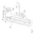
- the facility 300 after Figures 1A and 1B comprises a flat element 302 made of a plastic material for arranging or placing on a storage surface 304 of a storage element 306 for a goods shelf 308 and several signaling devices 309 (for the sake of clarity, only two signaling devices 309 are shown), each of which is used to signal a weight load in an area 338 of the Flat element 302 is provided by at least one product 305 arranged on the respective area 338 of the flat element 302, each area 338 being designed in the form of a longitudinal section 338 of the elongated flat element 302.
- the Figures 1A and 1B already illustrate the situation in which the flat element 302 is placed on the storage surface 304 or is arranged on it.
- Each signaling device 309 has a force sensor 310 for measuring the weight load, with each signaling device 309 - apart from respective signal conductors 332 and power supply conductors 320 and 321 of the respective signaling device 309 - being accommodated in the plastic material 346 of the flat element 302, so that the measuring surface 344 each force sensor 310 - to which the weight force transmitted from at least one product 305 to the flat element 302 is transferred for measuring the same - is accommodated in the plastic material 346.
- the weight load on the flat element 302 associated with the storage or arrangement is signaled by the respective signaling device 309, with the signaling of an existing weight load being signaled by a signal from the signaling device 309 is output, which therefore provides information about the weight load, this signal 309 in this exemplary embodiment being a signal which is generated or can be generated by an electronic signal generating device (not shown) of the signaling device 309, which is in the form of a square-wave signal 348 and from the signal generating device Measurement signal of the force sensor 310 is generated or is generated or formed on the basis of the measurement signal output by the force sensor 310.
- the square-wave signal 348 signals an existing weight load on the flat element 302 or the respective longitudinal section 338 of the flat element, wherein the square-wave signal 348 is or can be generated by the signal generating device when a signal threshold value of the measurement signal from the force sensor 310 is exceeded.
- the Fig. 1B also shows very schematically a system 10 according to the invention comprising the device 300 and a storage device 312 for the goods shelf 308 and a power supply system 352 for powering several electronic display devices 11 for displaying goods-related information.
- the storage device 312 has the storage element 306 with a storage surface 304 (cf. Fig. 1A ), on which the flat element 302 of the device 300 can be placed.
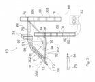
- the power supply system 352 is in Fig. 1 only shown sketchily and in Fig. 2 illustrated in more detail.
- the power supply system 352 (cf. Fig. 2 ) has an elongated base body 12 made of a plastic material that can be attached to the storage device 312 and a closing device 14. To attach or establish a connection between the base body 12 and the storage device 312, the base body 12 has two holding means 350, shown only very schematically, which can be received in a non-positive manner in receptacles of the storage device 312, not shown.
- the base body has a channel 16 extending over the entire length of the base body 12 for receiving the display devices 11.
- the base body 12 has two opposite end sections 18, each of the end sections 18 having one of two opposite channel end sections 20 of the channel 16.
- the display devices 11 can be accommodated in the channel 16.
- the current supply system 352 has two current conductors 21, 22, each of the current conductors 21, 21) having two current conductor end sections 24, 26 and an intermediate section 29.
- each current conductor 21, 22 is arranged in the channel 16 and one of the current conductor end sections 24, 26 of each current conductor 21, 22 is arranged in one of the two opposite channel end sections 20. So, for example, in the case of the current conductor 21, the current conductor end section 24 is arranged in one of the two channel end sections 20 and the current conductor end section 26 is arranged in the other of the two channel end sections 20.
- a power supply contact 28 of each display device 11 can be contacted in an electrically conductive manner with one of the current conductors 21, 22.
- the termination device 14 has four electrical supply lines 32, 34, 324, 326 and a signal transmission line 334.
- the supply lines 32, 34, 324, 326 are intended for establishing a connection to a power source 36 (illustrated in Fig. 2 already the connected state) and the signal transmission line 334 is intended for transmitting signals from the signaling devices 309 to a signal processing device 336.
- the termination device 14 can be connected to each of the two opposite end sections 18 of the base body 12.
- the base body 12 has a further or second channel 314 which extends over the entire length of the base body 12, wherein in the further channel 314 there is a busbar 316 which extends over the entire length of the channel 314 and has two busbars 316 extending in the longitudinal direction of the busbar 316 extending electrical busbar conductors 318, 319 and a signal conductor 330 extending in the longitudinal direction of the busbar 316.
- Each signaling device 309 has two power supply conductors 320, 321 (cf. Fig.1 ) for the power supply of the respective signaling device 309, with one end section 322 of each of the power supply conductors 320, 321 being connectable to one of the busbar conductors 318, 319 (see the schematic sketch Fig. 2 ).
- each signaling device 309 has a signal conductor 332 for forwarding signals from the signaling device 309.
- the signal conductor 332 of each of the signaling devices 309 can be connected to the signal conductor 330 of the busbar 316 (cf. the schematic sketch in Fig. 2 ).
- a supply line end section 38 of each of the supply lines 32, 34 can be electrically conductively contacted with a current conductor end section 24, 26 of the current conductor end sections 24, 26, which is in the channel -End section 20 of the end section 18 of the base body 12 are arranged.
- a supply line end section 328 of each of the further supply lines 324, 326 can also be contacted in an electrically conductive manner with a busbar conductor 318, 319 of the busbar 316.
- the signal conductor 330 of the busbar 316 can be connected to the signal transmission line 334 of the termination device 14 in a signal-transmitting manner.
- the terminating device 14 has two insertion pins 17, which can be inserted into receptacles (not shown) which are provided on the front side of the end sections 18 of the base body 12 (not shown).
- the display devices 11 can be successively accommodated in the channel 16 along the longitudinal axis 15 of the base body 202 in the channel 16, which is open or accessible on both end faces and on one long side, or forming a line along the longitudinal axis 15 of the base body 12 extending row in the channel 16 receivable or sequentially receivable.
- the display devices 11 can be received in the channel 16 in a force-fitting manner from the long side or the display devices 11 can be received in the channel 16 in a clamping manner from the long side.
- the current conductors 21, 22 are arranged in the channel 16 or are arranged completely or completely. Each current conductor 21, 22 is designed in the form of a straight conductor track 21, 22. Each conductor track 21, 22 is extruded onto the base body 12.
- the current conductors 21, 22 have the current conductor end sections 24, 26 and the intermediate sections 29, the respective current conductor end sections 24, 26 being connected to one another by the respective intermediate section 29.
- the respective intermediate section 29 is arranged in the channel 16 and the current conductor end sections 24, 26 are arranged in the respective channel end section 20 or are arranged completely or completely.
- a restriction to an arrangement or a complete arrangement of the current conductor end sections 24, 26 in the channel end sections 20 is of course not provided.
- at least one of the current conductor end sections 24, 26 can also be arranged, for example, with a partial section 31 outside the channel 16 and with a partial section 27 in the channel end section 20 - as in Fig. 2 for a current conductor end section 26 is illustrated schematically.
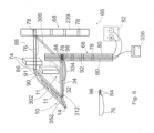
- a third exemplary embodiment of a system 10 according to the invention differs from the base body 12 Fig. 2 in particular in that the channel 16 of the extruded base body 12 comprises three contiguous subregions 97, 98 and 99, which are rectangular in cross section.
- a current conductor 21, 22 for powering the display devices is arranged in each of the smaller sub-areas 97, 98.
- the second or further channel 314 - in which the busbar 316 is arranged and which is open to a long side of the extruded base body 12 or is accessible from a long side of the base body 12 - advantageously has a small, space-saving channel depth.
- the end sections 322 of the respective power supply conductors 320, 321 of the respective signaling device 309 which can be connected to the busbar conductors 318, 319 are designed here in the form of contacts 322 of a connection element 354. Accordingly, the respective signal conductor 332 of the respective signaling device 309 also has a signal-transmitting contact element 333 for connection to the signal conductor 330 of the busbar 316, the contact element 333 being provided on the connection element 354.
- the base body 12 after Fig. 3 further has a third channel 356, in which a long lamp 358 is attached and arranged for illuminating adjacent storage devices.
- the base body 12 is designed to be attachable to the storage device 312 of the system 10 via a claw-like area 360.
- the final device 14 (cf. Fig. 4 ) of the power supply system 352 with the base body 12 according to the Fig. 3 has a flat body 40 made of a plastic material with two opposite sides 42 and 44 and an insert body 46 made of a plastic material connected to the side 42.
- the plug-in body 46 can be received in a non-positive manner in the channel 16 by inserting it into the channel 16 at the end.
- the supply line end sections 38 which can be contacted with the respective current conductor end sections of the channel 16, are on the plug-in body 46 is provided, wherein in this exemplary embodiment both the upper and lower supply line end sections 38 are each designed in the form of a double contact.
- the termination device 14 according to FIG. 9 also has a second and a third insertion body 112, 114.
- the second plug-in body 112 has two supply line end sections 328 in the form of contacting elements 328 for the power supply of the signaling devices 309, which can be contacted with respective busbar conductors by inserting the plug-in body 112 into the channel 314.
- the contacting elements 328 themselves are in turn electrically connected to a line, which is partially accommodated in a sheathing of a cable 117, in which the supply lines for powering the display devices 11 and the long lamp 358 are also partially accommodated.
- the second plug-in body 112 also has a connection device 362 of a signal transmission line, which is also accommodated in sections in the sheathing of the cable 117
- the third plug-in body 114 has two connection elements 118 for the power supply of the long lamp 358, which can be contacted with supply lines, not shown, of the long lamp 358, which are arranged in the channel 356, by inserting the plug-in body 112 into the channel 356.
- the connection elements 118 themselves are in turn electrically connected to a line, which is partially in the sheathing of the cable 117 is recorded.
- all of the supply lines accommodated in sections in the sheathing of the cable 117 can be energized via respective connection elements provided on at least one holding element by receiving the holding element in the respective receptacle of the holding post, namely to power the display devices 11, the signaling devices 309 and the long lamp 358.
- the respective end face of the base body 12 can be covered by the flat body 40 of the termination device 14 by inserting the insert body 46 and the insert bodies 112 and 114 into the channels 16, 314 and 356 at the end.
- the product presentation system 66 after Fig. 5 comprises a system 10 according to the invention with the storage device 312 and a goods shelf 308 with two holding posts 68, although in alternative embodiments a higher number of holding posts and storage devices can of course also be provided.
- the storage device 312 has the storage element 306 with the storage surface 304 and two holding elements 76.
- the holding elements 76 are detachably connected to the storage element 306, namely through receptacles, not shown, on the storage element 306, into which tabs of the holding elements 76, not shown, can be inserted.
- Each holding post 68 has four receptacles 78, with one of the holding elements 76 for holding the storage device 70 on the holding post 68 being receivable in each of the receptacles 78.
- the Fig. 5 already illustrates the state in which the holding elements 76 are accommodated in one of two opposing receptacles 78, one receptacle 78 being located on one holding post 68 and the other receptacles 78 being located on the other holding post 68.
- One of the two holding posts 68 has two electrical conductors 80 which are intended for connection to a power source 82.
- One of the holding elements 76 has two electrical connection elements 84, one of the supply lines 32, 34, 324, 326 of the termination device 14 being able to be connected to each connection element 84 in an electrically conductive manner.
- connection element 84 can be contacted in an electrically conductive manner with one of the conductors 80 of the holding post 68 by receiving the holding element 76 in the respective receptacle 78 of the holding post 68.
- the elongated base body 12 of the system 10 can be attached to the storage device 312, whereby the Fig. 4 already illustrates the appropriate condition.
- the storage element 306 is elongated and the elongated base body 12 can be attached to the storage device 312 in an arrangement in which a surface 90 of the base body 12 extending along the longitudinal axis 86 of the base body 12 is a surface extending along the longitudinal axis 88 of the storage element 306 91 of the storage element 306 faces.
- the product presentation system 66 after Fig. 6 differs from the product presentation system 66 Fig. 5 in that the holding post 68 additionally has a signal line 92 which is provided for transmitting signals from the signaling device(s) 309 to a signal processing device (336).
- the holding element 76 with the electrical connection elements 84 additionally has a signal line connection 96, wherein a signal transmission line 334 of the termination device 14 of the power supply system 352 can be connected to the signal line connection 96.
- the signal line connection 96 can be connected in a signal-transferable manner to the signal line 92 of the holding post 68 by receiving the holding element 76 in the receptacle 78 of the holding post 68.
Landscapes
- Physics & Mathematics (AREA)
- Engineering & Computer Science (AREA)
- Theoretical Computer Science (AREA)
- Mathematical Physics (AREA)
- General Physics & Mathematics (AREA)
- Business, Economics & Management (AREA)
- Economics (AREA)
- Development Economics (AREA)
- Finance (AREA)
- Accounting & Taxation (AREA)
- Entrepreneurship & Innovation (AREA)
- Human Resources & Organizations (AREA)
- Marketing (AREA)
- Operations Research (AREA)
- Quality & Reliability (AREA)
- Strategic Management (AREA)
- Tourism & Hospitality (AREA)
- General Business, Economics & Management (AREA)
- Display Racks (AREA)
Claims (6)
- Système (10) comprenant au moins un appareil (300), au moins un dispositif de dépôt (312) pour une étagère à marchandises (308) et un système d'alimentation électrique (352) pour l'alimentation électrique de plusieurs appareils d'affichage électroniques (11) pour afficher des informations relatives aux marchandises,
l'appareil (300) comprenant un élément plat (302) en une matière plastique destiné à être agencé sur une surface de dépôt (304) d'un élément de dépôt (306) du système (10) pour une étagère de marchandises (308) et au moins un appareil de signalisation (309) pour signaler une charge de poids d'au moins une zone de l'élément plat (302) par au moins une marchandise (305) agencée sur l'élément plat,- le dispositif de dépôt (312) présentant un élément de dépôt (306) avec une surface de dépôt (304) sur laquelle l'élément plat (302) peut être déposé,- le système d'alimentation électrique (352) présentant un corps de base (12) allongé en une matière plastique pouvant être disposé sur le dispositif de dépôt (312) et au moins un appareil de terminaison (14),- le corps de base (12) présentant un canal (16) s'étendant sur toute la longueur du corps de base (12) pour recevoir les appareils d'affichage (11),- le corps de base (12) présentant deux sections d'extrémité opposées (18), chacune des sections d'extrémité (18) présentant l'une de deux sections d'extrémité de canal opposées (20) du canal (16),- les appareils d'affichage (11) pouvant être reçus dans le canal (16),- le système d'alimentation électrique (352) présentant au moins deux conducteurs de courant (21, 22),- chacun des conducteurs de courant (21, 22) présentant deux sections d'extrémité de conducteur de courant (24, 26) et une section intermédiaire (29),- la section intermédiaire (29) de chaque conducteur de courant (21, 22) étant agencée dans le canal (16) et l'une des sections d'extrémité de conducteur de courant (24, 26) de chaque conducteur de courant (21, 22) étant agencée respectivement dans l'une des deux sections d'extrémité de canal opposées (20) avec au moins une section partielle (27),- par réception des appareils d'affichage (11) dans le canal (16), un contact d'alimentation en courant (28) de chaque appareil d'affichage (11) pouvant être mis en contact électriquement conducteur avec respectivement l'un des conducteurs de courant (21, 22),- l'appareil de terminaison (14) présentant au moins deux lignes d'alimentation électrique (32, 34) qui sont prévues pour établir une liaison avec une source de courant (36),- l'appareil de terminaison (14) pouvant être relié à au moins l'une des deux sections d'extrémité opposées (18) du corps de base (12),- par liaison de l'appareil de terminaison (14) à la section d'extrémité (18) du corps de base (12), une section d'extrémité de ligne d'alimentation (38) de chacune des lignes d'alimentation (32, 34) pouvant respectivement être mise en contact électriquement conducteur avec une section d'extrémité de conducteur de courant (24, 26) respective des sections d'extrémité de conducteur de courant (24, 26), qui sont agencées dans la section d'extrémité de canal (20) de la section d'extrémité (18) du corps de base (12) avec au moins une section partielle (27),- le corps de base (12) présentant un autre canal (314) qui s'étend sur toute la longueur du corps de base (12), une barre conductrice (316) étant agencée dans au moins une section de l'autre canal (314) avec au moins deux conducteurs électriques de barre conductrice (318, 319) s'étendant dans la direction longitudinale de la barre conductrice (316),- l'appareil de signalisation (309) présentant au moins deux conducteurs d'alimentation en courant (320, 321) pour l'alimentation en courant de l'appareil de signalisation (309), une section d'extrémité (322) de chacun des conducteurs d'alimentation en courant (320, 321) pouvant respectivement être raccordée à l'un respectif des conducteurs de barre conductrice (318, 319), l'autre canal (314) étant ouvert vers un côté longitudinal du corps de base (12), de telle sorte que les sections d'extrémité (322) des conducteurs d'alimentation en courant (320, 321) peuvent être raccordées aux conducteurs de barre conductrice (318, 319) depuis l'extérieur de l'autre canal (314),- l'appareil de terminaison (14) présentant au moins deux autres lignes d'alimentation électrique (324, 326) ; par liaison de l'appareil de terminaison (14) à la section d'extrémité (18) du corps de base (12), une section d'extrémité de ligne d'alimentation (328) de chacune des autres lignes d'alimentation (324, 326) pouvant respectivement être mise en contact électriquement conducteur avec un conducteur de barre conductrice (318, 319) respectif de la barre conductrice (316). - Système selon la revendication 1, caractérisé en ce que la barre conductrice (316) présente au moins un conducteur de signaux (330) s'étendant dans la direction longitudinale de la barre conductrice (316) pour la transmission de signaux,- l'appareil de signalisation (309) présentant au moins un conducteur de signaux (332) pour la transmission de signaux de l'appareil de signalisation (309), le conducteur de signaux (332) de l'appareil de signalisation (309) pouvant être raccordé au conducteur de signaux (330) de la barre conductrice (316),- l'appareil de terminaison (14) présentant au moins une ligne de transmission de signaux (334), qui est prévue pour la transmission de signaux de l'appareil de signalisation (309) à un appareil de traitement de signaux (336) ; par liaison de l'appareil de terminaison (14) à la section d'extrémité (18) du corps de base (12), le conducteur de signaux (330) de la barre conductrice (316) pouvant être relié à la ligne de transmission de signaux (334) de l'appareil de terminaison (14) en transmettant des signaux.
- Système de présentation de marchandises (66) comprenant un système (10) selon l'une quelconque des revendications 1 à 2 et au moins une étagère à marchandises (308) avec au moins deux montant de support (68),- le corps de base (12) du système d'alimentation électrique pouvant être disposé sur le dispositif de dépôt (312),- le dispositif de dépôt (312) présentant l'élément de dépôt (306) avec la surface de dépôt (304) et deux éléments de support (76),- les éléments de support (76) étant reliés à l'élément de dépôt (306),- chaque montant de support (68) présentant au moins un logement (78) dans lequel peut être reçu respectivement l'un des éléments de support (76) pour supporter le dispositif de dépôt (312) sur le montant de support (68),- au moins l'un des montants de support (68) présentant au moins deux conducteurs électriques (80) qui sont prévus pour être raccordés à une source de courant (82),- au moins l'un des éléments de support (76) présentant au moins deux éléments de raccordement électriques (84), l'une respective des lignes d'alimentation (32, 34, 324, 326) de l'appareil de terminaison (14) pouvant être raccordée à chaque élément de raccordement (84),- chaque élément de raccordement (84) pouvant être mis en contact électriquement conducteur avec l'un respectif des conducteurs (80) du montant de support (68) par réception de l'élément de support (76) dans le logement (78) du montant de support (68).
- Système de présentation de marchandises (66) selon la revendication 3, caractérisé en ce que l'élément de dépôt (306) est configuré sous forme allongée, le corps de base allongé (12) pouvant être disposé sur le dispositif de dépôt (312) dans un agencement dans lequel une surface (90) du corps de base (12) s'étendant le long de l'axe longitudinal (86) du corps de base (12) est tournée vers une surface (91) de l'élément de dépôt (306) s'étendant le long de l'axe longitudinal (88) de l'élément de dépôt (306).
- Système de présentation de marchandises (66) selon la revendication 3 ou 4, comprenant un système (10) selon la revendication 2, dans lequel au moins l'un des montants de support (68) présente au moins une ligne de signalisation (92) prévue pour transmettre des signaux de l'appareil de signalisation (309) à un appareil de traitement de signaux (336),- au moins l'un des montants de support (76) présentant au moins un raccordement de ligne de signaux (96), la ligne de transmission de signaux (334) de l'appareil de terminaison (14) pouvant être raccordée au raccordement de ligne de signaux (96),- le raccordement de ligne de signaux (96) pouvant être relié de manière à pouvoir transmettre des signaux à la ligne de signaux (92) du montant de support (68) par réception de l'élément de support (76) dans le logement (78) du montant de support (68).
- Système de présentation de marchandises (66) selon l'une quelconque des revendications 3 à 5, caractérisé en ce que les éléments de support (76) sont reliés de manière amovible à l'élément de dépôt (306).
Applications Claiming Priority (2)
| Application Number | Priority Date | Filing Date | Title |
|---|---|---|---|
| DE102016124951.3A DE102016124951A1 (de) | 2016-12-20 | 2016-12-20 | Einrichtung umfassend ein Flachelement zum Auflegen auf ein Ablageelement eines Warenregals und System und Warenpräsentationssystem mit einer derartigen Einrichtung |
| PCT/EP2017/083565 WO2018114962A1 (fr) | 2016-12-20 | 2017-12-19 | Dispositif comprenant un élément de surface destiné à être posé sur un élément de rangement d'un rayonnage à marchandises et système et système de présentation de marchandises équipé d'un dispositif de ce type |
Publications (2)
| Publication Number | Publication Date |
|---|---|
| EP3558066A1 EP3558066A1 (fr) | 2019-10-30 |
| EP3558066B1 true EP3558066B1 (fr) | 2023-10-25 |
Family
ID=60915501
Family Applications (1)
| Application Number | Title | Priority Date | Filing Date |
|---|---|---|---|
| EP17823096.7A Active EP3558066B1 (fr) | 2016-12-20 | 2017-12-19 | Dispositif comprenant un élément de surface destiné à être posé sur un élément de rangement d'un rayonnage à marchandises et système et système de présentation de marchandises équipé d'un dispositif de ce type |
Country Status (4)
| Country | Link |
|---|---|
| US (1) | US10976191B2 (fr) |
| EP (1) | EP3558066B1 (fr) |
| DE (1) | DE102016124951A1 (fr) |
| WO (1) | WO2018114962A1 (fr) |
Families Citing this family (7)
| Publication number | Priority date | Publication date | Assignee | Title |
|---|---|---|---|---|
| DE102016124956A1 (de) * | 2016-12-20 | 2018-06-21 | Rehau Ag + Co | System zur Bestromung mehrerer elektronischer Anzeigeeinrichtungen zur Anzeige von produktbezogenen Informationen und Warenpräsentationssystem |
| DE102017117177A1 (de) * | 2017-07-28 | 2019-01-31 | Adolf Würth Gmbh & Co Kg | Lagereinsatz für Lagervorrichtung mit an Unterseite anbringbarer Sensorleiste zum optischen Erfassen von an Oberseite lagerbarem Lagergut |
| CN110400110A (zh) * | 2019-07-26 | 2019-11-01 | 中国工商银行股份有限公司 | 库存管理的方法、装置、计算设备和介质 |
| US11732960B2 (en) * | 2021-02-11 | 2023-08-22 | Haier Us Appliance Solutions, Inc. | Refrigerator appliance having a weight-detecting shelf assembly |
| US11927389B2 (en) * | 2021-02-25 | 2024-03-12 | Haier Us Appliance Solutions, Inc. | Refrigerator appliance having a weight-detecting shelf assembly |
| CN113298210B (zh) * | 2021-05-06 | 2022-12-09 | 广州翼飞数字科技有限公司 | 一种无源电子纸货架标签系统 |
| US11841188B2 (en) * | 2022-02-15 | 2023-12-12 | Haier Us Appliance Solutions, Inc. | Refrigerator appliance and cantilever track with sensor |
Citations (1)
| Publication number | Priority date | Publication date | Assignee | Title |
|---|---|---|---|---|
| US20100103672A1 (en) * | 2006-06-30 | 2010-04-29 | James Thomas | Low-profile elongated LED light fixture |
Family Cites Families (19)
| Publication number | Priority date | Publication date | Assignee | Title |
|---|---|---|---|---|
| US3295093A (en) | 1963-05-21 | 1966-12-27 | Lightolier Inc | Electric power distribution conduit accessible for connection thereto along substantially its entire length |
| FR2671471A1 (fr) | 1991-01-15 | 1992-07-17 | Bancel Guy | Dispositif pour l'accrochage mural d'un objet, notamment d'un tableau. |
| EP0558305A3 (en) | 1992-02-24 | 1995-07-12 | Clares Regisbrook Systems | Apparatus and method for the supply of power and/or data with shelving systems |
| DE19714799C2 (de) * | 1997-04-10 | 2001-08-02 | Kristian Dicke | Vorrichtung zum Lagern von Wareneinheiten |
| US6231205B1 (en) | 1998-10-23 | 2001-05-15 | Powerwall, Inc. | Illuminated shelving |
| DE20221024U1 (de) | 2002-03-19 | 2005-02-24 | Semperlux Ag - Lichttechnische Werke - | Stromschiene mit Datenleitung |
| WO2005033645A1 (fr) | 2003-09-30 | 2005-04-14 | Intrinsic Marks International Llc | Procedes et systeme de surveillance d'articles |
| ATE318090T1 (de) * | 2003-12-08 | 2006-03-15 | Pos Tuning Udo Vosshenrich Gmb | Warenpräsentationsvorrichtung |
| EP1723597B1 (fr) * | 2004-03-11 | 2012-05-23 | Universität St. Gallen Hochschule für Wirtschafts-, Rechts- und Sozialwissenschaften (HSG) | Systeme de stockage et methode de gestion de stocks |
| US8915609B1 (en) | 2008-03-20 | 2014-12-23 | Cooper Technologies Company | Systems, methods, and devices for providing a track light and portable light |
| CN201804348U (zh) * | 2010-09-26 | 2011-04-20 | 传力电子衡器(南京)有限公司 | 仓储物料自动称重计数管理系统 |
| US9204736B2 (en) | 2012-08-22 | 2015-12-08 | Streater LLC | Shelving unit lighting system |
| CN104981825A (zh) * | 2013-01-11 | 2015-10-14 | 塔格尼蒂克斯股份有限公司 | 缺货传感器 |
| US10548418B2 (en) * | 2013-03-13 | 2020-02-04 | T+Ink, Inc. | Automatic sensing methods and devices for inventory control |
| DE102013004594A1 (de) * | 2013-03-15 | 2014-09-18 | Würth Elektronik Ics Gmbh & Co. Kg | Sensorvorrichtung sowie Sensorsystem, Behälter und Regalsystem mit einer Sensorvorrichtung und Herstellungsverfahren für eine Sensorvorrichtung |
| DE102015200330A1 (de) | 2015-01-13 | 2016-07-14 | Umdasch Shopfitting Gmbh | Aufnahme für elektronische Preisschilder, elektronisches Preisschild, Kombination von Aufnahme und Preisschild sowie Warenregal mit einer Aufnahme und/oder einer Kombination von Aufnahme und Preisschild |
| US20180181906A1 (en) | 2015-06-17 | 2018-06-28 | Panasonic Intellectual Property Management Co., Ltd. | Stock management apparatus, method and system |
| US10001402B1 (en) * | 2015-06-19 | 2018-06-19 | Amazon Technologies, Inc. | Instrumented item stowage system with modular elements |
| US10064502B1 (en) * | 2015-06-19 | 2018-09-04 | Amazon Technologies, Inc. | Shelf with integrated electronics |
-
2016
- 2016-12-20 DE DE102016124951.3A patent/DE102016124951A1/de not_active Withdrawn
-
2017
- 2017-12-19 EP EP17823096.7A patent/EP3558066B1/fr active Active
- 2017-12-19 US US16/467,962 patent/US10976191B2/en active Active
- 2017-12-19 WO PCT/EP2017/083565 patent/WO2018114962A1/fr not_active Ceased
Patent Citations (1)
| Publication number | Priority date | Publication date | Assignee | Title |
|---|---|---|---|---|
| US20100103672A1 (en) * | 2006-06-30 | 2010-04-29 | James Thomas | Low-profile elongated LED light fixture |
Also Published As
| Publication number | Publication date |
|---|---|
| US20200072659A1 (en) | 2020-03-05 |
| US10976191B2 (en) | 2021-04-13 |
| EP3558066A1 (fr) | 2019-10-30 |
| DE102016124951A1 (de) | 2018-06-21 |
| WO2018114962A1 (fr) | 2018-06-28 |
Similar Documents
| Publication | Publication Date | Title |
|---|---|---|
| EP3558066B1 (fr) | Dispositif comprenant un élément de surface destiné à être posé sur un élément de rangement d'un rayonnage à marchandises et système et système de présentation de marchandises équipé d'un dispositif de ce type | |
| EP3558065B1 (fr) | Système et method d'alimentation en courant électrique de plusieurs dispositifs d'affichage électroniques servant à l'affichage d'informations relatives à des produits | |
| EP3045088B1 (fr) | Dispositif de presentation, en particulier de marchandises | |
| DE102013114289A1 (de) | Regalsystem mit elektrischer Versorgung | |
| DE102009003509A1 (de) | Präsentationssystem mit Trägerprofilschiene | |
| EP3320811B1 (fr) | Dispositif de présentation | |
| AT13052U1 (de) | Vorrichtung zum verbinden und kontaktieren zumindest einer led-einheit, sowie led-einheit und leuchtsystem | |
| AT13533U1 (de) | Regalpfosten | |
| EP3609369B1 (fr) | Système d'alimentation en courant électrique de plusieurs dispositifs d'affichage électroniques servant à l'affichage d'informations relatives à des produits et système de présentation de marchandises | |
| EP3609368B1 (fr) | Systeme d'affichage électronique | |
| DE202016100561U1 (de) | Vorrichtung zur Strom- und/oder Signalübertragung von an einem Regal, insbesondere einem Verkaufsregal anzuordnenden Abnehmern | |
| DE102019133435B4 (de) | Warenpräsentationsregal und Verfahren zum Aufbau | |
| EP3559547B1 (fr) | Appareil de présentation de produit avec système d'alimentation électrique | |
| DE202015002216U1 (de) | Datenkommunikationsvorrichtung, Informationswiedergabeeinrichtung sowie Anzeigevorrichtung zur Verwendung in einer solchen | |
| DE202013009962U1 (de) | Stromzuführung für eine Beleuchtungsvorrichtung einer Schiebetüre eines Schranks | |
| DE3412687A1 (de) | Produktinformations- und display-system | |
| DE102009046734A1 (de) | Vorschubvorrichtung und Verfahren zur Bestimmung einer Position einer Vorschubeinheit einer Vorschubvorrichtung | |
| DE102020103442A1 (de) | Möbelstück zum Lagern und/oder Präsentieren von Gegenständen | |
| DE102017100958A1 (de) | Elektrifizierung für Hänge- und/oder Regalsysteme | |
| DE102015003723A1 (de) | Datenkommunikationsvorrichtung, Informationswiedergabeeinrichtung sowie Anzeigevorrichtung zur Verwendung in einer solchen | |
| DE102012105252A1 (de) | Kontaktschienen-System für Elektro-Anschluss und Positionierung von LED-Platinen | |
| DE202014105612U1 (de) | Displayanordnung | |
| DE202006005361U1 (de) | Vorrichtung zur Auf- und/oder Entladung eines elektrischen Energiespeichers | |
| DE102015003722A1 (de) | Datenkommunikationsvorrichtung, Informationswiedergabeeinrichtung sowie Anzeigevorrichtung zur Verwendung in einer solchen | |
| DE102015003729A1 (de) | Datenkommunikationsvorrichtung, Informationswiedergabeeinrichtung sowie Anzeigevorrichtung zur Verwendung in einer solchen |
Legal Events
| Date | Code | Title | Description |
|---|---|---|---|
| STAA | Information on the status of an ep patent application or granted ep patent |
Free format text: STATUS: UNKNOWN |
|
| STAA | Information on the status of an ep patent application or granted ep patent |
Free format text: STATUS: THE INTERNATIONAL PUBLICATION HAS BEEN MADE |
|
| PUAI | Public reference made under article 153(3) epc to a published international application that has entered the european phase |
Free format text: ORIGINAL CODE: 0009012 |
|
| STAA | Information on the status of an ep patent application or granted ep patent |
Free format text: STATUS: REQUEST FOR EXAMINATION WAS MADE |
|
| 17P | Request for examination filed |
Effective date: 20190624 |
|
| AK | Designated contracting states |
Kind code of ref document: A1 Designated state(s): AL AT BE BG CH CY CZ DE DK EE ES FI FR GB GR HR HU IE IS IT LI LT LU LV MC MK MT NL NO PL PT RO RS SE SI SK SM TR |
|
| AX | Request for extension of the european patent |
Extension state: BA ME |
|
| RIN1 | Information on inventor provided before grant (corrected) |
Inventor name: SCHMIDT, STEVEN Inventor name: EIBL, STEFAN Inventor name: NIEHOFF, ANSGAR Inventor name: BUEHLMEYER, CHRISTIAN Inventor name: MICHELS, PETER Inventor name: PARDOS, SANTIAGO Inventor name: GOLDSTEIN, JOERG |
|
| DAV | Request for validation of the european patent (deleted) | ||
| DAX | Request for extension of the european patent (deleted) | ||
| RAP1 | Party data changed (applicant data changed or rights of an application transferred) |
Owner name: REHAU AG + CO |
|
| RAP1 | Party data changed (applicant data changed or rights of an application transferred) |
Owner name: REHAU INDUSTRIES SE & CO. KG |
|
| STAA | Information on the status of an ep patent application or granted ep patent |
Free format text: STATUS: EXAMINATION IS IN PROGRESS |
|
| 17Q | First examination report despatched |
Effective date: 20220513 |
|
| RAP3 | Party data changed (applicant data changed or rights of an application transferred) |
Owner name: REHAU INDUSTRIES SE & CO. KG |
|
| GRAP | Despatch of communication of intention to grant a patent |
Free format text: ORIGINAL CODE: EPIDOSNIGR1 |
|
| STAA | Information on the status of an ep patent application or granted ep patent |
Free format text: STATUS: GRANT OF PATENT IS INTENDED |
|
| INTG | Intention to grant announced |
Effective date: 20230731 |
|
| GRAS | Grant fee paid |
Free format text: ORIGINAL CODE: EPIDOSNIGR3 |
|
| GRAA | (expected) grant |
Free format text: ORIGINAL CODE: 0009210 |
|
| STAA | Information on the status of an ep patent application or granted ep patent |
Free format text: STATUS: THE PATENT HAS BEEN GRANTED |
|
| AK | Designated contracting states |
Kind code of ref document: B1 Designated state(s): AL AT BE BG CH CY CZ DE DK EE ES FI FR GB GR HR HU IE IS IT LI LT LU LV MC MK MT NL NO PL PT RO RS SE SI SK SM TR |
|
| REG | Reference to a national code |
Ref country code: GB Ref legal event code: FG4D Free format text: NOT ENGLISH |
|
| REG | Reference to a national code |
Ref country code: CH Ref legal event code: EP |
|
| REG | Reference to a national code |
Ref country code: DE Ref legal event code: R096 Ref document number: 502017015540 Country of ref document: DE |
|
| REG | Reference to a national code |
Ref country code: IE Ref legal event code: FG4D Free format text: LANGUAGE OF EP DOCUMENT: GERMAN |
|
| REG | Reference to a national code |
Ref country code: LT Ref legal event code: MG9D |
|
| REG | Reference to a national code |
Ref country code: NL Ref legal event code: MP Effective date: 20231025 |
|
| PG25 | Lapsed in a contracting state [announced via postgrant information from national office to epo] |
Ref country code: NL Free format text: LAPSE BECAUSE OF FAILURE TO SUBMIT A TRANSLATION OF THE DESCRIPTION OR TO PAY THE FEE WITHIN THE PRESCRIBED TIME-LIMIT Effective date: 20231025 |
|
| PG25 | Lapsed in a contracting state [announced via postgrant information from national office to epo] |
Ref country code: GR Free format text: LAPSE BECAUSE OF FAILURE TO SUBMIT A TRANSLATION OF THE DESCRIPTION OR TO PAY THE FEE WITHIN THE PRESCRIBED TIME-LIMIT Effective date: 20240126 |
|
| PG25 | Lapsed in a contracting state [announced via postgrant information from national office to epo] |
Ref country code: IS Free format text: LAPSE BECAUSE OF FAILURE TO SUBMIT A TRANSLATION OF THE DESCRIPTION OR TO PAY THE FEE WITHIN THE PRESCRIBED TIME-LIMIT Effective date: 20240225 |
|
| PG25 | Lapsed in a contracting state [announced via postgrant information from national office to epo] |
Ref country code: LT Free format text: LAPSE BECAUSE OF FAILURE TO SUBMIT A TRANSLATION OF THE DESCRIPTION OR TO PAY THE FEE WITHIN THE PRESCRIBED TIME-LIMIT Effective date: 20231025 |
|
| PG25 | Lapsed in a contracting state [announced via postgrant information from national office to epo] |
Ref country code: ES Free format text: LAPSE BECAUSE OF FAILURE TO SUBMIT A TRANSLATION OF THE DESCRIPTION OR TO PAY THE FEE WITHIN THE PRESCRIBED TIME-LIMIT Effective date: 20231025 |
|
| PG25 | Lapsed in a contracting state [announced via postgrant information from national office to epo] |
Ref country code: LT Free format text: LAPSE BECAUSE OF FAILURE TO SUBMIT A TRANSLATION OF THE DESCRIPTION OR TO PAY THE FEE WITHIN THE PRESCRIBED TIME-LIMIT Effective date: 20231025 Ref country code: IS Free format text: LAPSE BECAUSE OF FAILURE TO SUBMIT A TRANSLATION OF THE DESCRIPTION OR TO PAY THE FEE WITHIN THE PRESCRIBED TIME-LIMIT Effective date: 20240225 Ref country code: GR Free format text: LAPSE BECAUSE OF FAILURE TO SUBMIT A TRANSLATION OF THE DESCRIPTION OR TO PAY THE FEE WITHIN THE PRESCRIBED TIME-LIMIT Effective date: 20240126 Ref country code: ES Free format text: LAPSE BECAUSE OF FAILURE TO SUBMIT A TRANSLATION OF THE DESCRIPTION OR TO PAY THE FEE WITHIN THE PRESCRIBED TIME-LIMIT Effective date: 20231025 Ref country code: BG Free format text: LAPSE BECAUSE OF FAILURE TO SUBMIT A TRANSLATION OF THE DESCRIPTION OR TO PAY THE FEE WITHIN THE PRESCRIBED TIME-LIMIT Effective date: 20240125 Ref country code: PT Free format text: LAPSE BECAUSE OF FAILURE TO SUBMIT A TRANSLATION OF THE DESCRIPTION OR TO PAY THE FEE WITHIN THE PRESCRIBED TIME-LIMIT Effective date: 20240226 |
|
| PG25 | Lapsed in a contracting state [announced via postgrant information from national office to epo] |
Ref country code: SE Free format text: LAPSE BECAUSE OF FAILURE TO SUBMIT A TRANSLATION OF THE DESCRIPTION OR TO PAY THE FEE WITHIN THE PRESCRIBED TIME-LIMIT Effective date: 20231025 Ref country code: RS Free format text: LAPSE BECAUSE OF FAILURE TO SUBMIT A TRANSLATION OF THE DESCRIPTION OR TO PAY THE FEE WITHIN THE PRESCRIBED TIME-LIMIT Effective date: 20231025 Ref country code: PL Free format text: LAPSE BECAUSE OF FAILURE TO SUBMIT A TRANSLATION OF THE DESCRIPTION OR TO PAY THE FEE WITHIN THE PRESCRIBED TIME-LIMIT Effective date: 20231025 Ref country code: NO Free format text: LAPSE BECAUSE OF FAILURE TO SUBMIT A TRANSLATION OF THE DESCRIPTION OR TO PAY THE FEE WITHIN THE PRESCRIBED TIME-LIMIT Effective date: 20240125 Ref country code: LV Free format text: LAPSE BECAUSE OF FAILURE TO SUBMIT A TRANSLATION OF THE DESCRIPTION OR TO PAY THE FEE WITHIN THE PRESCRIBED TIME-LIMIT Effective date: 20231025 Ref country code: HR Free format text: LAPSE BECAUSE OF FAILURE TO SUBMIT A TRANSLATION OF THE DESCRIPTION OR TO PAY THE FEE WITHIN THE PRESCRIBED TIME-LIMIT Effective date: 20231025 |
|
| PG25 | Lapsed in a contracting state [announced via postgrant information from national office to epo] |
Ref country code: DK Free format text: LAPSE BECAUSE OF FAILURE TO SUBMIT A TRANSLATION OF THE DESCRIPTION OR TO PAY THE FEE WITHIN THE PRESCRIBED TIME-LIMIT Effective date: 20231025 |
|
| PG25 | Lapsed in a contracting state [announced via postgrant information from national office to epo] |
Ref country code: CZ Free format text: LAPSE BECAUSE OF FAILURE TO SUBMIT A TRANSLATION OF THE DESCRIPTION OR TO PAY THE FEE WITHIN THE PRESCRIBED TIME-LIMIT Effective date: 20231025 |
|
| REG | Reference to a national code |
Ref country code: DE Ref legal event code: R097 Ref document number: 502017015540 Country of ref document: DE |
|
| PG25 | Lapsed in a contracting state [announced via postgrant information from national office to epo] |
Ref country code: SK Free format text: LAPSE BECAUSE OF FAILURE TO SUBMIT A TRANSLATION OF THE DESCRIPTION OR TO PAY THE FEE WITHIN THE PRESCRIBED TIME-LIMIT Effective date: 20231025 |
|
| PG25 | Lapsed in a contracting state [announced via postgrant information from national office to epo] |
Ref country code: SM Free format text: LAPSE BECAUSE OF FAILURE TO SUBMIT A TRANSLATION OF THE DESCRIPTION OR TO PAY THE FEE WITHIN THE PRESCRIBED TIME-LIMIT Effective date: 20231025 Ref country code: SK Free format text: LAPSE BECAUSE OF FAILURE TO SUBMIT A TRANSLATION OF THE DESCRIPTION OR TO PAY THE FEE WITHIN THE PRESCRIBED TIME-LIMIT Effective date: 20231025 Ref country code: RO Free format text: LAPSE BECAUSE OF FAILURE TO SUBMIT A TRANSLATION OF THE DESCRIPTION OR TO PAY THE FEE WITHIN THE PRESCRIBED TIME-LIMIT Effective date: 20231025 Ref country code: IT Free format text: LAPSE BECAUSE OF FAILURE TO SUBMIT A TRANSLATION OF THE DESCRIPTION OR TO PAY THE FEE WITHIN THE PRESCRIBED TIME-LIMIT Effective date: 20231025 Ref country code: EE Free format text: LAPSE BECAUSE OF FAILURE TO SUBMIT A TRANSLATION OF THE DESCRIPTION OR TO PAY THE FEE WITHIN THE PRESCRIBED TIME-LIMIT Effective date: 20231025 Ref country code: DK Free format text: LAPSE BECAUSE OF FAILURE TO SUBMIT A TRANSLATION OF THE DESCRIPTION OR TO PAY THE FEE WITHIN THE PRESCRIBED TIME-LIMIT Effective date: 20231025 Ref country code: CZ Free format text: LAPSE BECAUSE OF FAILURE TO SUBMIT A TRANSLATION OF THE DESCRIPTION OR TO PAY THE FEE WITHIN THE PRESCRIBED TIME-LIMIT Effective date: 20231025 |
|
| REG | Reference to a national code |
Ref country code: CH Ref legal event code: PL |
|
| PG25 | Lapsed in a contracting state [announced via postgrant information from national office to epo] |
Ref country code: LU Free format text: LAPSE BECAUSE OF NON-PAYMENT OF DUE FEES Effective date: 20231219 |
|
| PG25 | Lapsed in a contracting state [announced via postgrant information from national office to epo] |
Ref country code: MC Free format text: LAPSE BECAUSE OF FAILURE TO SUBMIT A TRANSLATION OF THE DESCRIPTION OR TO PAY THE FEE WITHIN THE PRESCRIBED TIME-LIMIT Effective date: 20231025 |
|
| REG | Reference to a national code |
Ref country code: BE Ref legal event code: MM Effective date: 20231231 |
|
| PG25 | Lapsed in a contracting state [announced via postgrant information from national office to epo] |
Ref country code: MC Free format text: LAPSE BECAUSE OF FAILURE TO SUBMIT A TRANSLATION OF THE DESCRIPTION OR TO PAY THE FEE WITHIN THE PRESCRIBED TIME-LIMIT Effective date: 20231025 Ref country code: LU Free format text: LAPSE BECAUSE OF NON-PAYMENT OF DUE FEES Effective date: 20231219 |
|
| PLBE | No opposition filed within time limit |
Free format text: ORIGINAL CODE: 0009261 |
|
| STAA | Information on the status of an ep patent application or granted ep patent |
Free format text: STATUS: NO OPPOSITION FILED WITHIN TIME LIMIT |
|
| GBPC | Gb: european patent ceased through non-payment of renewal fee |
Effective date: 20240125 |
|
| 26N | No opposition filed |
Effective date: 20240726 |
|
| REG | Reference to a national code |
Ref country code: IE Ref legal event code: MM4A |
|
| PG25 | Lapsed in a contracting state [announced via postgrant information from national office to epo] |
Ref country code: IE Free format text: LAPSE BECAUSE OF NON-PAYMENT OF DUE FEES Effective date: 20231219 |
|
| PG25 | Lapsed in a contracting state [announced via postgrant information from national office to epo] |
Ref country code: GB Free format text: LAPSE BECAUSE OF NON-PAYMENT OF DUE FEES Effective date: 20240125 |
|
| PG25 | Lapsed in a contracting state [announced via postgrant information from national office to epo] |
Ref country code: BE Free format text: LAPSE BECAUSE OF NON-PAYMENT OF DUE FEES Effective date: 20231231 |
|
| PG25 | Lapsed in a contracting state [announced via postgrant information from national office to epo] |
Ref country code: FR Free format text: LAPSE BECAUSE OF NON-PAYMENT OF DUE FEES Effective date: 20231225 |
|
| PG25 | Lapsed in a contracting state [announced via postgrant information from national office to epo] |
Ref country code: CH Free format text: LAPSE BECAUSE OF NON-PAYMENT OF DUE FEES Effective date: 20231231 |
|
| PG25 | Lapsed in a contracting state [announced via postgrant information from national office to epo] |
Ref country code: SI Free format text: LAPSE BECAUSE OF FAILURE TO SUBMIT A TRANSLATION OF THE DESCRIPTION OR TO PAY THE FEE WITHIN THE PRESCRIBED TIME-LIMIT Effective date: 20231025 |
|
| PG25 | Lapsed in a contracting state [announced via postgrant information from national office to epo] |
Ref country code: SI Free format text: LAPSE BECAUSE OF FAILURE TO SUBMIT A TRANSLATION OF THE DESCRIPTION OR TO PAY THE FEE WITHIN THE PRESCRIBED TIME-LIMIT Effective date: 20231025 Ref country code: IE Free format text: LAPSE BECAUSE OF NON-PAYMENT OF DUE FEES Effective date: 20231219 Ref country code: GB Free format text: LAPSE BECAUSE OF NON-PAYMENT OF DUE FEES Effective date: 20240125 Ref country code: FR Free format text: LAPSE BECAUSE OF NON-PAYMENT OF DUE FEES Effective date: 20231225 Ref country code: CH Free format text: LAPSE BECAUSE OF NON-PAYMENT OF DUE FEES Effective date: 20231231 Ref country code: BE Free format text: LAPSE BECAUSE OF NON-PAYMENT OF DUE FEES Effective date: 20231231 |
|
| PG25 | Lapsed in a contracting state [announced via postgrant information from national office to epo] |
Ref country code: FI Free format text: LAPSE BECAUSE OF FAILURE TO SUBMIT A TRANSLATION OF THE DESCRIPTION OR TO PAY THE FEE WITHIN THE PRESCRIBED TIME-LIMIT Effective date: 20231025 |
|
| PG25 | Lapsed in a contracting state [announced via postgrant information from national office to epo] |
Ref country code: CY Free format text: LAPSE BECAUSE OF FAILURE TO SUBMIT A TRANSLATION OF THE DESCRIPTION OR TO PAY THE FEE WITHIN THE PRESCRIBED TIME-LIMIT; INVALID AB INITIO Effective date: 20171219 |
|
| PG25 | Lapsed in a contracting state [announced via postgrant information from national office to epo] |
Ref country code: HU Free format text: LAPSE BECAUSE OF FAILURE TO SUBMIT A TRANSLATION OF THE DESCRIPTION OR TO PAY THE FEE WITHIN THE PRESCRIBED TIME-LIMIT; INVALID AB INITIO Effective date: 20171219 |
|
| PG25 | Lapsed in a contracting state [announced via postgrant information from national office to epo] |
Ref country code: TR Free format text: LAPSE BECAUSE OF FAILURE TO SUBMIT A TRANSLATION OF THE DESCRIPTION OR TO PAY THE FEE WITHIN THE PRESCRIBED TIME-LIMIT Effective date: 20231025 |
|
| PGFP | Annual fee paid to national office [announced via postgrant information from national office to epo] |
Ref country code: AT Payment date: 20251120 Year of fee payment: 9 |
|
| PGFP | Annual fee paid to national office [announced via postgrant information from national office to epo] |
Ref country code: DE Payment date: 20251231 Year of fee payment: 9 |