EP3558066B1 - Device comprising a flat element for laying onto a shelf element of a goods rack and system and goods presentation system having such a device - Google Patents
Device comprising a flat element for laying onto a shelf element of a goods rack and system and goods presentation system having such a device Download PDFInfo
- Publication number
- EP3558066B1 EP3558066B1 EP17823096.7A EP17823096A EP3558066B1 EP 3558066 B1 EP3558066 B1 EP 3558066B1 EP 17823096 A EP17823096 A EP 17823096A EP 3558066 B1 EP3558066 B1 EP 3558066B1
- Authority
- EP
- European Patent Office
- Prior art keywords
- base body
- channel
- shelf
- signal
- conductors
- Prior art date
- Legal status (The legal status is an assumption and is not a legal conclusion. Google has not performed a legal analysis and makes no representation as to the accuracy of the status listed.)
- Active
Links
- 239000004020 conductor Substances 0.000 claims description 172
- 230000011664 signaling Effects 0.000 claims description 98
- 239000004033 plastic Substances 0.000 claims description 29
- 229920003023 plastic Polymers 0.000 claims description 29
- 239000000463 material Substances 0.000 claims description 28
- 230000008054 signal transmission Effects 0.000 claims description 16
- 238000012545 processing Methods 0.000 claims description 13
- 238000003860 storage Methods 0.000 description 85
- 238000005259 measurement Methods 0.000 description 11
- 238000003780 insertion Methods 0.000 description 8
- 230000037431 insertion Effects 0.000 description 8
- 238000013461 design Methods 0.000 description 5
- 238000000034 method Methods 0.000 description 5
- 229920001169 thermoplastic Polymers 0.000 description 5
- 239000004416 thermosoftening plastic Substances 0.000 description 5
- 238000001125 extrusion Methods 0.000 description 4
- 238000007726 management method Methods 0.000 description 4
- 239000004417 polycarbonate Substances 0.000 description 4
- -1 polypropylene Polymers 0.000 description 4
- OKTJSMMVPCPJKN-UHFFFAOYSA-N Carbon Chemical compound [C] OKTJSMMVPCPJKN-UHFFFAOYSA-N 0.000 description 2
- 239000004698 Polyethylene Substances 0.000 description 2
- 239000004743 Polypropylene Substances 0.000 description 2
- XAGFODPZIPBFFR-UHFFFAOYSA-N aluminium Chemical compound [Al] XAGFODPZIPBFFR-UHFFFAOYSA-N 0.000 description 2
- 229910052782 aluminium Inorganic materials 0.000 description 2
- 238000006243 chemical reaction Methods 0.000 description 2
- 229920001971 elastomer Polymers 0.000 description 2
- 239000000806 elastomer Substances 0.000 description 2
- 238000009434 installation Methods 0.000 description 2
- 238000012423 maintenance Methods 0.000 description 2
- 230000013011 mating Effects 0.000 description 2
- 229920000058 polyacrylate Polymers 0.000 description 2
- 229920000515 polycarbonate Polymers 0.000 description 2
- 229920000728 polyester Polymers 0.000 description 2
- 229920000573 polyethylene Polymers 0.000 description 2
- 229920000098 polyolefin Polymers 0.000 description 2
- 229920001155 polypropylene Polymers 0.000 description 2
- 230000008439 repair process Effects 0.000 description 2
- 229920001187 thermosetting polymer Polymers 0.000 description 2
- XMWRBQBLMFGWIX-UHFFFAOYSA-N C60 fullerene Chemical class C12=C3C(C4=C56)=C7C8=C5C5=C9C%10=C6C6=C4C1=C1C4=C6C6=C%10C%10=C9C9=C%11C5=C8C5=C8C7=C3C3=C7C2=C1C1=C2C4=C6C4=C%10C6=C9C9=C%11C5=C5C8=C3C3=C7C1=C1C2=C4C6=C2C9=C5C3=C12 XMWRBQBLMFGWIX-UHFFFAOYSA-N 0.000 description 1
- RYGMFSIKBFXOCR-UHFFFAOYSA-N Copper Chemical compound [Cu] RYGMFSIKBFXOCR-UHFFFAOYSA-N 0.000 description 1
- 230000005540 biological transmission Effects 0.000 description 1
- 229910052799 carbon Inorganic materials 0.000 description 1
- 239000002041 carbon nanotube Substances 0.000 description 1
- 229920001940 conductive polymer Polymers 0.000 description 1
- 229910052802 copper Inorganic materials 0.000 description 1
- 239000010949 copper Substances 0.000 description 1
- 238000000151 deposition Methods 0.000 description 1
- 238000001514 detection method Methods 0.000 description 1
- 229910003472 fullerene Inorganic materials 0.000 description 1
- PCHJSUWPFVWCPO-UHFFFAOYSA-N gold Chemical compound [Au] PCHJSUWPFVWCPO-UHFFFAOYSA-N 0.000 description 1
- 229910052737 gold Inorganic materials 0.000 description 1
- 239000010931 gold Substances 0.000 description 1
- 229910002804 graphite Inorganic materials 0.000 description 1
- 239000010439 graphite Substances 0.000 description 1
- 238000004519 manufacturing process Methods 0.000 description 1
- 238000012986 modification Methods 0.000 description 1
- 230000004048 modification Effects 0.000 description 1
- 229920000767 polyaniline Polymers 0.000 description 1
- 229910052709 silver Inorganic materials 0.000 description 1
- 239000004332 silver Substances 0.000 description 1
- 239000012815 thermoplastic material Substances 0.000 description 1
Images


Classifications
-
- G—PHYSICS
- G01—MEASURING; TESTING
- G01G—WEIGHING
- G01G19/00—Weighing apparatus or methods adapted for special purposes not provided for in the preceding groups
- G01G19/40—Weighing apparatus or methods adapted for special purposes not provided for in the preceding groups with provisions for indicating, recording, or computing price or other quantities dependent on the weight
- G01G19/413—Weighing apparatus or methods adapted for special purposes not provided for in the preceding groups with provisions for indicating, recording, or computing price or other quantities dependent on the weight using electromechanical or electronic computing means
- G01G19/414—Weighing apparatus or methods adapted for special purposes not provided for in the preceding groups with provisions for indicating, recording, or computing price or other quantities dependent on the weight using electromechanical or electronic computing means using electronic computing means only
- G01G19/4144—Weighing apparatus or methods adapted for special purposes not provided for in the preceding groups with provisions for indicating, recording, or computing price or other quantities dependent on the weight using electromechanical or electronic computing means using electronic computing means only for controlling weight of goods in commercial establishments, e.g. supermarket, P.O.S. systems
-
- A—HUMAN NECESSITIES
- A47—FURNITURE; DOMESTIC ARTICLES OR APPLIANCES; COFFEE MILLS; SPICE MILLS; SUCTION CLEANERS IN GENERAL
- A47F—SPECIAL FURNITURE, FITTINGS, OR ACCESSORIES FOR SHOPS, STOREHOUSES, BARS, RESTAURANTS OR THE LIKE; PAYING COUNTERS
- A47F10/00—Furniture or installations specially adapted to particular types of service systems, not otherwise provided for
- A47F10/02—Furniture or installations specially adapted to particular types of service systems, not otherwise provided for for self-service type systems, e.g. supermarkets
-
- A—HUMAN NECESSITIES
- A47—FURNITURE; DOMESTIC ARTICLES OR APPLIANCES; COFFEE MILLS; SPICE MILLS; SUCTION CLEANERS IN GENERAL
- A47B—TABLES; DESKS; OFFICE FURNITURE; CABINETS; DRAWERS; GENERAL DETAILS OF FURNITURE
- A47B96/00—Details of cabinets, racks or shelf units not covered by a single one of groups A47B43/00 - A47B95/00; General details of furniture
- A47B96/02—Shelves
- A47B96/021—Structural features of shelf bases
-
- G—PHYSICS
- G01—MEASURING; TESTING
- G01G—WEIGHING
- G01G19/00—Weighing apparatus or methods adapted for special purposes not provided for in the preceding groups
- G01G19/40—Weighing apparatus or methods adapted for special purposes not provided for in the preceding groups with provisions for indicating, recording, or computing price or other quantities dependent on the weight
- G01G19/42—Weighing apparatus or methods adapted for special purposes not provided for in the preceding groups with provisions for indicating, recording, or computing price or other quantities dependent on the weight for counting by weighing
-
- G—PHYSICS
- G06—COMPUTING; CALCULATING OR COUNTING
- G06Q—INFORMATION AND COMMUNICATION TECHNOLOGY [ICT] SPECIALLY ADAPTED FOR ADMINISTRATIVE, COMMERCIAL, FINANCIAL, MANAGERIAL OR SUPERVISORY PURPOSES; SYSTEMS OR METHODS SPECIALLY ADAPTED FOR ADMINISTRATIVE, COMMERCIAL, FINANCIAL, MANAGERIAL OR SUPERVISORY PURPOSES, NOT OTHERWISE PROVIDED FOR
- G06Q10/00—Administration; Management
- G06Q10/08—Logistics, e.g. warehousing, loading or distribution; Inventory or stock management
- G06Q10/087—Inventory or stock management, e.g. order filling, procurement or balancing against orders
-
- A—HUMAN NECESSITIES
- A47—FURNITURE; DOMESTIC ARTICLES OR APPLIANCES; COFFEE MILLS; SPICE MILLS; SUCTION CLEANERS IN GENERAL
- A47F—SPECIAL FURNITURE, FITTINGS, OR ACCESSORIES FOR SHOPS, STOREHOUSES, BARS, RESTAURANTS OR THE LIKE; PAYING COUNTERS
- A47F10/00—Furniture or installations specially adapted to particular types of service systems, not otherwise provided for
- A47F10/02—Furniture or installations specially adapted to particular types of service systems, not otherwise provided for for self-service type systems, e.g. supermarkets
- A47F2010/025—Furniture or installations specially adapted to particular types of service systems, not otherwise provided for for self-service type systems, e.g. supermarkets using stock management systems
Definitions
- the present invention relates to a system comprising at least one device, at least one storage device for a goods shelf and a power supply system for powering several electronic display devices for displaying goods-related information, the device being designed with a flat element made of a plastic material and with a signaling device.
- From the US 2014/0201041 A is a weight recording system for retail shelves.
- From the WO 2005/033645 A1 a detection system for objects is known.
- From the WO 2016/205629 A1 A warehouse management device, a warehouse management system and a warehouse management method are known.
- From the US 2010/103672 A1 an elongated lighting fixture with light-emitting diodes is known.
- Goods registration systems process this as an essential input variable existing inventory of goods, which usually - for example as part of an inventory - has to be determined in a technically very complex and also usually very labor-intensive manner by recording the goods arranged or stored on the storage devices or shelves of the goods shelves.
- An inventory of goods determined at different times is also an important input variable for determining the product-related purchasing behavior of potential buyers or customers. Specifically, for example, it can be determined to what extent the demand for a certain product changes over time. However, the determination of purchasing behavior is also very personnel-intensive and technically very complex, particularly due to the labor-intensive and technically very complex determination of the inventory.
- the present invention is therefore based on the object of specifying a system with a device that can help to significantly reduce the effort required to determine product-related purchasing behavior.
- the device of the system according to the invention comprises a flat element, for example made of a plastic material, for arranging or depositing on a storage surface of a storage element for a goods shelf or a goods shelf and at least one electrical signaling device or signaling device for signaling a weight load of at least one area of the flat element by at least one goods arranged or placed on the flat element or by at least one goods arranged or placed on a flat side of the flat element.
- a flat element for example made of a plastic material, for arranging or depositing on a storage surface of a storage element for a goods shelf or a goods shelf and at least one electrical signaling device or signaling device for signaling a weight load of at least one area of the flat element by at least one goods arranged or placed on the flat element or by at least one goods arranged or placed on a flat side of the flat element.
- the electrical signaling device or the signaling device which is provided for signaling a weight load on at least one area of the flat element by at least one item arranged or placed on the flat element, is therefore an electrical signaling device or a signaling device for signaling a Weight loading of at least one area of the flat element by at least one product arranged on the flat element or for signaling a weight force transmitted to at least one area of the flat element by at least one product arranged on the flat element.
- the flat element can be arranged or placed on the storage surface to form at least one flat contact between one of the two flat sides of the flat element and the storage surface.
- a flat element it has a thickness or thickness extension that is smaller or significantly smaller than the length or width of the flat element.
- the facility can help to significantly reduce the effort required to determine product-related purchasing behavior.
- the device can be used to determine purchasing behavior or contribute to this in that the flat element is arranged or placed on a storage surface of a storage element of a goods shelf in the respective sales area (such as a sales area in a supermarket or drugstore) and then a or several goods to be offered for sale are placed or arranged on the compartment element.
- the weight load on the flat element associated with the storage or arrangement is - if the goods or goods have been placed on an area in which the signaling device can signal a weight load caused by the goods or goods - signaled by the signaling device, whereby the Signaling of an existing weight load particularly preferably by a signal output by the signaling device or electrical signal occurs, which provides information about the weight load.
- this signal could be a signal generated or capable of being generated by a signal generating device of the signaling device or a signal generated or capable of being generated by a signal generator of the signaling device.
- This signal or electrical signal could be particularly practical, for example in the form of a square wave signal.
- the signal can in particular also be a digital signal generated by analog/digital conversion, which can advantageously be further processed using a computer or a data processing device of a goods registration system, for example in a supermarket or, for example, in a drugstore.
- the duration or durations of the time period or periods of a predetermined period of time in which a signal characterizing the weight load occurs or is present can be combined with the duration or durations of the time period or periods of the predetermined period of time in which If this signal is missing, it can advantageously be used as information or usable information for determining product-related purchasing behavior.
- the durations of these time periods - after any necessary digitization of the durations - can be used advantageously, in particular, for a computer-based determination of product-related purchasing behavior using procedures or methods familiar to those skilled in the art.
- time periods for purchasing behavior results, for example, from the fact that in the time periods with the signal or signals characterizing the weight load, the product or goods are located on the flat element and in the time periods in which the The signal indicating the weight load is missing and there are no goods left on the flat element, for example because they were taken away by the customer.
- the signaling device does not have to be set up to measure the value or exact value of the respective weight load. It is only necessary that the signaling device determines that a weight load is present, which is typically the case, for example, when measuring a load that exceeds a load threshold using a weight force measuring device of the signaling device.
- the use of the device according to the invention or the use of a plurality of the devices according to the invention can contribute to reducing the effort required to determine product-related purchasing behavior compared to the known ones Solutions can be significantly reduced, since the enabled signaling of the weight load on the flat element by the goods or goods makes it possible, in particular, to computer-aided determination of the goods-related purchasing behavior without a lot of personnel effort and also without a lot of technical effort. For example, from the signaling of a weight load by the signal characterizing the weight load and a subsequent absence of the signal characterizing the weight load for more than a minute, it can be concluded with a high degree of probability that the customer actually wants to buy the product. If the signal indicating the weight load occurs again earlier, it can be concluded with high probability that the goods have been put back by the customer and there is no interest in purchasing them.
- the device can also be used in particular advantageously for determining the inventory of the goods or goods placed on the flat element, namely the inventory of goods can be compared to the known solutions due to what has been stated above compared to the known solutions can be accomplished with significantly less effort, in particular the personnel required for inventory determination can be saved using the device according to the invention.
- the device also solves the task of significantly reducing the effort required to determine the inventory of a goods shelf.
- the invention therefore also relates to the use of the device for determining an inventory of goods on a goods shelf.
- the device can in particular also have a plurality of signaling devices, each of the signaling devices preferably signaling or being able to signal a weight load on an area of the flat element assigned to it by at least one product.
- the purchasing behavior or the inventory of goods for a large number of goods stored on the respective storage element can be monitored for the respective storage element.
- the signaling devices are set up to output signals, the signals output or generated by the respective signaling devices can be processed after any necessary analog/digital conversion via a computer, which is based on the signals or .Data the inventory or purchasing behavior in a manner familiar to those skilled in the art via a Computer connected display device, such as a large central screen in a management room of a department store.
- the signaling device or the respective signaling device can have a reporting device and can be set up to control the reporting device for the purpose of reporting the weight load or the absence of weight load in the presence or absence of an existing weight load on the flat element by at least one item.
- the message could be realized, for example, by illuminating a lamp in the signaling device.
- the signaling device for signaling a weight load of at least one area of the flat element by at least one product arranged on the flat element particularly preferably has at least one force sensor for measuring the weight load, which is arranged or attached to the flat element.
- the force sensor is a force sensor for measuring or electrically measuring a weight force acting on the force sensor or for measuring or electrically measuring a weight load on the force sensor, the measuring surface of the force sensor via which the weight force to be measured enters the force sensor to be initiated to measure the same or via which the weight force to be measured is to be transmitted to the force sensor, has an arrangement in relation to the flat element, in which a weight load on the flat element caused by one or more goods can be measured by the force sensor.
- the measuring surface of the force sensor is particularly preferably arranged parallel or particularly preferably substantially parallel to one of the two flat sides of the flat element.
- the force sensor can in particular be attached to the flat element in such a way that the measuring surface of the force sensor is located above the flat element or between the flat element and the storage surface of the storage element when the flat element is placed on the storage surface of the storage element.
- the signaling device can also be partially embedded in the plastic material of the flat element in such a way that the measuring surface of the force sensor is embedded in the plastic material of the flat element or that the measuring surface of the force sensor is accommodated in the plastic material, the plastic material particularly preferably made of a thermoplastic, such as polypropylene or polyethylene, exists to ensure effective power transmission to be able to realize the weight force through the plastic material of the flat element onto the measuring surface of the force sensor.
- the force sensor can be a force sensor familiar to those skilled in the art.
- it can be a force sensor with strain gauges or, for example, a piezo force sensor or a piezoelectric force sensor or, for example, a resistive force sensor.
- the signaling of an existing weight load on the flat element can, as already explained above, particularly preferably take place by a signal issued by the signaling device, which therefore provides information about the weight load.
- this signal could be a signal generated or capable of being generated by a signal generating device of the signaling device or a signal generated or capable of being generated by a signal generator of the signaling device, the signal generating device or signal generator preferably generating or generating this signal from the measurement signal output by the force sensor. forms or generates or forms based on the measurement signal output by the force sensor.
- This electrical signal could be particularly practical, for example in the form of a square-wave signal, which can be generated by the signal generating device when a signal threshold value of the measurement signal from the force sensor is exceeded or fallen below.
- the signaling device is a signaling device for signaling a weight load on at least one area of the flat element by at least one product arranged on the flat element.
- the signaling device can be a signaling device which is set up to signal a weight force which is transmitted from at least one product to the flat element via any partial area of one of the flat sides of the flat element. This can be done particularly practically in such a way that the signaling device has a force sensor for measuring the weight load with a measuring area that corresponds to the area size of the flat side or is larger than this.
- the storage surface of the storage element is a storage surface for storing or arranging at least one product, on which, according to the invention, the flat element is to be placed or laid flat instead of the product or goods.
- the at least one product must be placed or arranged for the purpose of determining the product-specific purchasing behavior or the product-specific inventory.
- the flat element is elongated and the device has a plurality of signaling devices, each with a force sensor, the measuring surfaces of the signaling devices particularly preferably being arranged in rows one after the other in the longitudinal direction of the flat element.
- the force sensors By arranging the force sensors in rows, a signaling option about existing weight loads of placed goods over the entire length of the flat element is advantageously realized.
- a signaling device can be provided for each section of the flat element, and therefore each signaling device can be provided for at least one product that may be arranged on the respective section or can signal a weight load. Overall, this design can advantageously be used to implement goods-specific signaling of the weight loads for a large number of goods without much effort.
- a system comprising at least one device, at least one storage device for a goods shelf and a power supply system for powering several electronic display devices for displaying goods-related information, the storage device having a storage element with a Has a storage surface on which the flat element can be placed, the power supply system having an elongated base body made of a plastic material that can be attached to the storage device and at least one closing device, the base body having a channel extending over the entire length of the base body for receiving the display devices, the Base body has two opposite end sections, each of the end sections having one of two opposite channel end sections of the channel, the display devices being receivable in the channel, the current supply system having at least two current conductors, each of the current conductors having two current conductor end sections and an intermediate section , wherein the intermediate section of each current conductor is arranged in the channel and one of the current conductor end sections of each current conductor is arranged in one of the two opposite channel end
- the elongated base body made of a plastic material is particularly preferably an extruded base body or a base body produced by extrusion.
- Such base bodies can be produced cost-effectively in a large variety and of high, consistent quality.
- Suitable materials for this are thermoplastic materials, such as polypropylene or polyethylene.
- the elongated base body made of a plastic material for attachment to the storage device or storage device for the goods shelf or the goods shelf is therefore an elongated base body which is intended for attachment to the storage device or which can be attached to or with the storage device Storage device can be connected.
- the storage device can in particular comprise a shelf of a goods shelf or for a goods shelf or can be designed in the form of a shelf of a goods shelf or for a goods shelf.
- the base body can, for example, have at least one area that can be received in a receptacle provided on the storage device.
- the at least one area can also be a hook-shaped area, for example, which can be hooked into a receptacle provided on the storage device.
- the power supply system for powering several display devices for displaying goods-related information has the elongated base body made of a plastic material and at least one termination device.
- the base body which is preferably an extruded base body or a base body produced by extrusion, has a channel extending over the entire length of the base body for accommodating the display devices or the base body has an elongated receptacle extending over the entire length of the base body for accommodating the display devices.
- the channel or the receptacle extends over the entire length of the base body or the channel or the receptacle extends from one of two opposite ends of the base body to the other of the two opposite ends of the base body.
- the base body has two opposite end sections or the base body has two longitudinally opposite end sections, each of the end sections of the base body having one or one of two opposite channel end sections of the channel or one or one of two longitudinally opposite each other has opposite channel end sections of the channel (or has one of two opposite receiving end sections of the receptacle or has one of two longitudinally opposite receiving end sections of the receptacle) or wherein in each case one of two opposite - or longitudinally to each other There is a channel end section or a receiving end section in each of the opposite end sections of the base body.
- the display devices are receivable in the channel, the display devices being receivable in the channel in order to realize a series of successively arranged display devices, preferably along the longitudinal axis of the base body, or forming a row in the channel extending along the longitudinal axis of the base body can be recorded or can be recorded sequentially.
- This row-shaped arrangement advantageously enables the power supply system to be arranged in the vicinity of a goods shelf, in which one display device can be assigned directly to the associated goods by the potential buyer or prospective buyer, namely the goods from several goods, which are also placed in rows one after the other on the storage device or one Shelf of a goods shelf are placed or arranged.
- the channel of the base body which is provided or set up to accommodate the display devices, extends over the entire length of the base body.
- the channel is particularly preferably a channel aligned parallel to the longitudinal axis of the base body or the channel is particularly preferably an elongated channel aligned parallel to the longitudinal axis of the base body. If it is preferably an extruded base body, the channel is a channel formed when the base body is extruded.
- the channel or the receptacle is open or accessible to both end faces of the base body.
- the channel is also open or accessible to a long side of the base body, so that the display devices can be accommodated in the channel from the long side. This has the advantage that the display devices do not have to be inserted one after the other into the channel in order to realize a series of display devices arranged one after the other on the base body, which can be difficult due to tilting depending on the design of the channel.
- the or each of the display devices can be accommodated in the channel, whereby the or each display device can be accommodated in the channel in particular in a non-positive manner.
- the or each display device can form a releasable snap connection by being accommodated in the channel with the extruded base body.
- the current supply system has at least two power conductors arranged in the channel, each of the power conductors having two power conductor end sections and an intermediate section, the intermediate section of each power conductor being arranged in the channel and one of the power conductor end sections of each power conductor in each of the two opposite ones Channel end sections are arranged with at least one section.
- the spaced-apart power conductors can be power conductors with a design familiar to those skilled in the art.
- the current conductors can be designed in particular in the form of conductor tracks, with the conductor tracks being, for example, conductor tracks made of copper, of copper-plated aluminum or of galvanized aluminum or of copper-plated gold or of silver or of graphite or of conductive polymers (such as PEDOT-PSS, PANI , etc.) or from various carbon modifications (such as CNTs, fullerenes etc.).
- the conductor tracks can be extruded or laminated or printed onto the plastic material of the base body, for example, or each of the conductor tracks can be in the form of a to hold them in the channel elongated section of an elongated conductive body, wherein a further section of the elongated conductive body can be extruded, pressed, glued or clipped into the plastic material of the extruded base body, for example.
- the system according to the invention is characterized, on the one hand, in that by accommodating the display devices in the channel, a power supply contact of each display device can be contacted in an electrically conductive manner with one of the current conductors.
- a power supply contact of each display device can be contacted in an electrically conductive manner with one of the current conductors.
- the system according to the invention is characterized in that the terminating device or the at least one terminating device has at least two electrical supply lines which are intended to establish a connection to a power source or which are intended to be connected to a power source, the terminating device can be connected to at least one of the two opposite end sections of the base body, and wherein by connecting the termination device to the end section of the base body, a supply line end section (or supply line end section) of each of the supply lines can be contacted in an electrically conductive manner with a current conductor end section of the current conductor end sections which are arranged in the channel end section of the end section of the base body with at least one partial section.
- the intended contactability of the power supply contacts of each of the display devices with the power conductors arranged in the channel by accommodating the display devices in the channel together with the electrical contacting of the supply line end sections of the termination device with the power conductor end sections of the power conductors, which can be achieved by simply connecting the termination device to the end section
- a very simple and practical way of providing the power supply or voltage supply to the display devices via the electrical supply lines of the termination device which are intended to establish a connection with a power source or an external power source or which are intended to establish an electrically conductive connection with a power source or an external power source or with a voltage source or with an external voltage source.
- the power supply of all display devices can therefore be realized simply by accommodating the display devices in the channel, connecting the terminating device to the end section of the base body, then connecting the supply lines of the terminating device to a power source or electrically conductive connections of the supply lines to a power source are produced and the display devices are energized by the power source via the supply lines or are supplied with a supply voltage, for example in the case of a direct current source, this can be done by connecting one of the supply lines to the positive pole of the power source and the other of the two supply lines to the Negative pole of the power source is connected.
- the cabling effort for providing the power supply can be reduced or significantly reduced.
- the display devices for displaying goods-related information or product-related information can be common or known display devices or electronic display devices which are intended or set up for displaying goods-related information or product-related information and which typically have an electronic display .
- they can be display devices with an electronic display, which are designed in the form of so-called ESLs (Electronic Shelf Labels), which are also referred to as electronic price tags.
- ESLs Electronic Shelf Labels
- these displays may have a length within a range of 2 to 125 cm, a height within a range of 2 to 50 cm, and a thickness within a range of 0.2 to 2 cm.
- the product-related information can be any information about the respective product, e.g. the price of the product, the name of the product, the expiry date, the weight, etc.
- each of the current conductors has two current conductor end sections, one of which is arranged in one of the two opposite channel end sections with at least one partial section. This means that in one of the current conductors, a first of the two current conductor end sections is arranged in a first of the two opposite channel end sections with at least one partial section and the second current conductor end section of this current conductor is arranged in the second of the two opposite channel end sections with at least is arranged in a section.
- An intermediate section of the respective power conductor which extends from the first power conductor end section to the second power conductor end section or connects the first power conductor end section to the second power conductor end section, is then arranged in a central region of the channel, which is from the first channel end section extends to the second channel end section.
- Each of the current conductors particularly preferably extends over the entire length of the base body.
- each of the current conductors is particularly preferably designed to be rectilinear and particularly preferably extends parallel or essentially parallel to the longitudinal axis of the extruded base body. However, this is not mandatory.
- all that can be achieved is that by accommodating the display devices in the channel, one of the power supply contacts of each display device can be contacted in an electrically conductive manner with one of the current conductors.
- This contactability can be achieved in a manner familiar to those skilled in the art, in particular by suitably adapting the dimensions of the channel to the relevant dimensions of the display device(s).
- the termination device has at least two electrical supply lines which are provided for establishing a connection to a power source or for connecting to a power source. It is understood that the supply lines can, at least in sections, be current-carrying conductors or inner conductors or cores of a supply cable, which are particularly preferably current-carrying conductors or inner conductors of a single supply cable.
- each of the current conductor end sections can also be designed, for example, in the form of a current-conducting contact of a plug or mating plug. It understands also that each of the supply line end sections can also be designed in the form of a current-conducting contact of a corresponding mating connector or plug, so that by connecting the termination device to the end section of the base body, plug connections can also be formed in order to ensure the electrically conductive contact or the to realize electrically conductive connection between the supply line end sections and the power conductor end sections.
- the termination device can be connected to at least one of the two opposite end sections of the base body, the termination device being particularly preferably non-positively connectable to the end section of the base body.
- the termination device can preferably have an insert body which can be inserted into the channel of the extruded base body on the end face in order to form a non-positive connection with the extruded base body.
- the termination device can be releasably connected or manually releasably connected to at least one of the two opposite end sections of the base body, so that the termination device can advantageously be detached from the preferably extruded base body, in particular for maintenance or repair purposes, and can also be reconnected to it if necessary.
- a supply line end section of each of the supply lines can be contacted in an electrically conductive manner with a current conductor end section of the current conductor end sections, which are arranged in the channel end section of the end section with at least one partial section.
- This contact can be made in a manner familiar to those skilled in the art, in particular through a suitable arrangement of the supply line end sections.
- each of the supply line end sections can protrude, in particular, into the channel of the base body in order to make contact with the current conductor end sections, each of which is arranged with at least one section in the channel.
- Each current conductor has two current conductor end sections, one of which is arranged in one of the two opposite channel end sections with at least one partial section.
- the respective current conductor end section is therefore arranged with at least one partial section in one of the two opposite channel end sections, so that the respective current conductor end section is in particular also complete or to Can be arranged entirely in the respective channel end section or can be arranged in the channel, without protruding from the channel end section.
- the device described above is combined with the advantageous power supply system described above for powering the display devices, so that overall it is advantageously possible to provide the power supply or voltage supply to the display devices in a very simple and practical manner in conjunction with a device, which can advantageously help to significantly reduce the effort required to determine product-related purchasing behavior or inventory.
- the base body has a further channel which extends over the entire length of the base body, with a busbar having at least two electrical busbar conductors extending in the longitudinal direction of the busbar being arranged in at least one section of the further channel, the signaling device having at least two Power supply conductors for the power supply of the signaling device, with one end section of each of the power supply conductors being connectable to one of the busbar conductors, the further channel being open towards a longitudinal side of the base body, so that the end sections of the power supply conductors come from outside the further channel the busbar conductors can be connected, the termination device having at least two further electrical supply lines which are provided for establishing a connection to a power source, by connecting the termination device to the end section of the base body or to one of the two end sections of the base body Supply line end section of each of the further supply lines can be contacted in an electrically conductive manner with a busbar conductor of the busbar or with an end section of the busbar conductor.
- electrically conductive connections can be made to the further supply lines of the termination device by simply removably connecting the termination device to an end section of the base body to supply power to the signaling device, which in turn are used to establish a connection with a power source are provided.
- the further or second channel is open towards a long side of the base body, so that the end sections of the power supply conductors of the signaling device(s) can be connected to the busbar conductors from outside the further channel.
- the busbar can also have or additionally have at least one signal conductor extending in the longitudinal direction of the busbar for forwarding signals, wherein (also) the signaling device has at least one signal conductor for forwarding signals or measurement signals of the signaling device , wherein the signal conductor of the signaling device can be connected to the signal conductor of the busbar, wherein the terminating device - in addition to the electrical supply lines - has at least one signal transmission line which is provided for transmitting measurement signals from the signaling device to a measurement signal processing device, wherein by connecting the terminating device to the end section of the base body, the signal conductor of the busbar can be connected to the signal transmission line in a signal-transmitting manner.
- a signal-transmittable connection can be established between the signal conductor(s) of the signaling device(s) and the (the) signal transmission line(s) of the termination device are produced.
- a signal-transmittable connection can then be established via the signal transmission line(s) of the termination device to a measurement signal processing device or signal processing device, which is set up or provided for the processing of measurement signals or signals for signaling an existing weight load on the flat element.
- the busbar can particularly advantageously extend over the entire length of the base body of the power supply system.
- the termination device has a flat body made of a plastic material with two opposite sides and at least two plug-in bodies made of a plastic material connected to one of the two sides, one of the plug-in bodies being intended for insertion into the channel for receiving the display devices, wherein a further insertion body is provided for insertion into the channel in which the busbar is arranged, each insertion body being able to be received in a force-fitting manner in the respective channel for connecting the termination device to the end section of the base body by inserting it into the respective channel at the end.
- this termination device By means of this termination device, a connection of the supply line end sections to the power conductor end sections and/or the signal transmission line to the signal conductor of the busbar can be realized in a very simple and practical manner by a simple insertion process.
- the provision of the flat body advantageously enables a weight-saving and visually appealing design of the flat body.
- the plug-in bodies are designed to connect the end device to the end section of the base body by being inserted into the respective channel at the end in a non-positive manner, or can be received in full or at least in part, or each plug-in body is for connecting the end device to the end section of the base body By inserting it into the respective channel at the front, it is particularly preferably held in a clamping manner or can be held in the respective channel by forming a clamping tension.
- the connection between the termination device and the base body that can be achieved by means of this preferred embodiment can particularly preferably be a detachable or manually detachable connection.
- Each of the plug-in bodies can therefore particularly preferably be pulled out of the respective channel or can be pulled out manually from the respective channel. Due to the preferably provided releasability of the connection between the termination device and the base body, maintenance work or repairs in particular can advantageously be carried out in a simple and practical manner.
- the plastic material from which the flat body and each of the plug-in bodies is made can be, for example, thermoplastics, thermoset plastics and elastomers.
- Preferred thermoplastics are: PVC, ABS, ASA, PET, PC, PS, PA as well as all plastics from the group of polyolefins, polyacrylates, polycarbonates and polyesters.
- the supply line end sections which can be contacted with the power conductor end sections of the power conductors for supplying the display devices are particularly preferably provided on the plug-in body for insertion into the channel for receiving the display devices. Since the plug-in body can be non-positively received in the channel by inserting it, stable electrically conductive contacts between the supply line end sections and the power conductor end sections can advantageously be realized by providing the supply line end sections on the plug-in body. Accordingly, the further supply line end sections, each of which can be contacted in an electrically conductive manner with a busbar conductor, are particularly preferably provided on the further plug-in body in order to be able to advantageously realize the stable electrically conductive contacts.
- the front side of the base body can be covered by the flat element by inserting the plug-in bodies into the channels on the front side.
- the covering option provided here allows a visually very appealing finish to be created.
- the flat element can have a design that is advantageous can be connected flush to the base body by inserting the plug-in body into the channel at the front, thereby creating a visually very attractive finish.
- the elongated base body of the current supply system is advantageously an extruded base body made of a plastic material, i.e. a base body produced by extrusion.
- a plastic material i.e. a base body produced by extrusion.
- the plastic material from which the base body is made can be, for example, thermoplastics, thermoset plastics and elastomers.
- Preferred thermoplastics are: PVC, ABS, ASA, PET, PC, PS, PA as well as all plastics from the group of polyolefins, polyacrylates, polycarbonates and polyesters.
- the invention also relates to a goods presentation system comprising at least one system according to the invention and at least one goods shelf with at least two holding posts, the base body of the power supply system being attachable to the storage device, the storage device having the storage element with the storage surface and two holding elements, the holding elements with the storage element are connected, with each holding post having at least one receptacle into which one of the holding elements for holding the storage device on the holding post can be received, with at least one of the holding posts having at least two electrical conductors which are provided for connection to a power source, with at least one the holding elements have at least two electrical connection elements, wherein one of the supply lines of the termination device can be connected to each connection element, each connection element being electrically conductively contactable with one of the conductors of the holding post by receiving the holding element in the receptacle of the holding post.
- the goods presentation system is characterized in that it combines the advantages of the above system according to the invention with at least one goods shelf with at least two support posts.
- the holding posts and the at least one storage device of the goods shelf are characterized in that via the electrical conductors of the holding posts and the electrical connection elements of the holding elements after connecting the supply lines of the termination device to the connection elements Electrically conductive connections of the supply lines of the termination device to the power source can be produced by simply removably accommodating the holding elements in the receptacles of the holding posts - namely for holding or attaching the storage device to the holding post - and subsequently connecting the conductors of the holding post to a power source for energizing or supplying voltage to electronic display devices accommodated in the channel of the base body of the energization system and/or for energizing or supplying voltage to the signaling devices that can be energized via the busbar).
- Each holding post has at least one receptacle or several receptacles, into which one of the holding elements for holding the storage device on the holding post can be received.
- each of the holding elements can have an end region that can be hooked into the respective receptacle, wherein the electrical connection elements can be provided on the end region.
- the conductors of the holding posts can be arranged in a longitudinal channel of the holding post or the respective holding post, with an electrically conductive contact to the respective electrical conductor of the holding post being present for each connection element in the suspended state of the end region.
- the elongated base body of the system according to the invention can be attached to the storage device or connected to the storage device.
- the elongated base body of the current supply system can particularly preferably be attached to the storage device in an arrangement in which a surface of the base body extending along the longitudinal axis of the base body faces a surface of the storage element extending along the longitudinal axis of the storage element.
- the elongated base body of the power supply system can particularly preferably be attached to the storage device in such a way that a surface of the base body extending along the longitudinal axis of the base body faces a surface of the storage element extending along the longitudinal axis of the storage element is.
- the channels of the base body of the current supply system are particularly preferably parallel to the longitudinal axis of the storage element or the storage device, the buyers or potential buyers can advantageously establish a direct reference to the display device provided for the respective goods.
- the holding elements are preferably detachably connected to the storage element.
- this comprises the above system with the signal conductors, with at least one of the holding posts having at least one signal line which is provided for transmitting signals from the signaling device to a signal processing device, with at least one of the holding elements having at least one signal line connection, wherein an the signal line connection, the signal transmission line of the termination device can be connected, wherein the signal line connection can be connected in a signal-transferable manner to the signal line of the holding post by receiving the holding element in the receptacle of the holding post.
- a transmission of signals from the signaling device to the signal processing device can advantageously be realized in addition by simply connecting the signal transmission line of the termination device to the signal line connection, receiving the holding elements in the receptacles of the holding post and signal-transferably connecting the signal line of the holding post to a signal processing device to process these, for example, to determine purchasing behavior or, for example, to determine inventory levels.
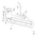
- the facility 300 after Figures 1A and 1B comprises a flat element 302 made of a plastic material for arranging or placing on a storage surface 304 of a storage element 306 for a goods shelf 308 and several signaling devices 309 (for the sake of clarity, only two signaling devices 309 are shown), each of which is used to signal a weight load in an area 338 of the Flat element 302 is provided by at least one product 305 arranged on the respective area 338 of the flat element 302, each area 338 being designed in the form of a longitudinal section 338 of the elongated flat element 302.
- the Figures 1A and 1B already illustrate the situation in which the flat element 302 is placed on the storage surface 304 or is arranged on it.
- Each signaling device 309 has a force sensor 310 for measuring the weight load, with each signaling device 309 - apart from respective signal conductors 332 and power supply conductors 320 and 321 of the respective signaling device 309 - being accommodated in the plastic material 346 of the flat element 302, so that the measuring surface 344 each force sensor 310 - to which the weight force transmitted from at least one product 305 to the flat element 302 is transferred for measuring the same - is accommodated in the plastic material 346.
- the weight load on the flat element 302 associated with the storage or arrangement is signaled by the respective signaling device 309, with the signaling of an existing weight load being signaled by a signal from the signaling device 309 is output, which therefore provides information about the weight load, this signal 309 in this exemplary embodiment being a signal which is generated or can be generated by an electronic signal generating device (not shown) of the signaling device 309, which is in the form of a square-wave signal 348 and from the signal generating device Measurement signal of the force sensor 310 is generated or is generated or formed on the basis of the measurement signal output by the force sensor 310.
- the square-wave signal 348 signals an existing weight load on the flat element 302 or the respective longitudinal section 338 of the flat element, wherein the square-wave signal 348 is or can be generated by the signal generating device when a signal threshold value of the measurement signal from the force sensor 310 is exceeded.
- the Fig. 1B also shows very schematically a system 10 according to the invention comprising the device 300 and a storage device 312 for the goods shelf 308 and a power supply system 352 for powering several electronic display devices 11 for displaying goods-related information.
- the storage device 312 has the storage element 306 with a storage surface 304 (cf. Fig. 1A ), on which the flat element 302 of the device 300 can be placed.
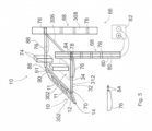
- the power supply system 352 is in Fig. 1 only shown sketchily and in Fig. 2 illustrated in more detail.
- the power supply system 352 (cf. Fig. 2 ) has an elongated base body 12 made of a plastic material that can be attached to the storage device 312 and a closing device 14. To attach or establish a connection between the base body 12 and the storage device 312, the base body 12 has two holding means 350, shown only very schematically, which can be received in a non-positive manner in receptacles of the storage device 312, not shown.
- the base body has a channel 16 extending over the entire length of the base body 12 for receiving the display devices 11.
- the base body 12 has two opposite end sections 18, each of the end sections 18 having one of two opposite channel end sections 20 of the channel 16.
- the display devices 11 can be accommodated in the channel 16.
- the current supply system 352 has two current conductors 21, 22, each of the current conductors 21, 21) having two current conductor end sections 24, 26 and an intermediate section 29.
- each current conductor 21, 22 is arranged in the channel 16 and one of the current conductor end sections 24, 26 of each current conductor 21, 22 is arranged in one of the two opposite channel end sections 20. So, for example, in the case of the current conductor 21, the current conductor end section 24 is arranged in one of the two channel end sections 20 and the current conductor end section 26 is arranged in the other of the two channel end sections 20.
- a power supply contact 28 of each display device 11 can be contacted in an electrically conductive manner with one of the current conductors 21, 22.
- the termination device 14 has four electrical supply lines 32, 34, 324, 326 and a signal transmission line 334.
- the supply lines 32, 34, 324, 326 are intended for establishing a connection to a power source 36 (illustrated in Fig. 2 already the connected state) and the signal transmission line 334 is intended for transmitting signals from the signaling devices 309 to a signal processing device 336.
- the termination device 14 can be connected to each of the two opposite end sections 18 of the base body 12.
- the base body 12 has a further or second channel 314 which extends over the entire length of the base body 12, wherein in the further channel 314 there is a busbar 316 which extends over the entire length of the channel 314 and has two busbars 316 extending in the longitudinal direction of the busbar 316 extending electrical busbar conductors 318, 319 and a signal conductor 330 extending in the longitudinal direction of the busbar 316.
- Each signaling device 309 has two power supply conductors 320, 321 (cf. Fig.1 ) for the power supply of the respective signaling device 309, with one end section 322 of each of the power supply conductors 320, 321 being connectable to one of the busbar conductors 318, 319 (see the schematic sketch Fig. 2 ).
- each signaling device 309 has a signal conductor 332 for forwarding signals from the signaling device 309.
- the signal conductor 332 of each of the signaling devices 309 can be connected to the signal conductor 330 of the busbar 316 (cf. the schematic sketch in Fig. 2 ).
- a supply line end section 38 of each of the supply lines 32, 34 can be electrically conductively contacted with a current conductor end section 24, 26 of the current conductor end sections 24, 26, which is in the channel -End section 20 of the end section 18 of the base body 12 are arranged.
- a supply line end section 328 of each of the further supply lines 324, 326 can also be contacted in an electrically conductive manner with a busbar conductor 318, 319 of the busbar 316.
- the signal conductor 330 of the busbar 316 can be connected to the signal transmission line 334 of the termination device 14 in a signal-transmitting manner.
- the terminating device 14 has two insertion pins 17, which can be inserted into receptacles (not shown) which are provided on the front side of the end sections 18 of the base body 12 (not shown).
- the display devices 11 can be successively accommodated in the channel 16 along the longitudinal axis 15 of the base body 202 in the channel 16, which is open or accessible on both end faces and on one long side, or forming a line along the longitudinal axis 15 of the base body 12 extending row in the channel 16 receivable or sequentially receivable.
- the display devices 11 can be received in the channel 16 in a force-fitting manner from the long side or the display devices 11 can be received in the channel 16 in a clamping manner from the long side.
- the current conductors 21, 22 are arranged in the channel 16 or are arranged completely or completely. Each current conductor 21, 22 is designed in the form of a straight conductor track 21, 22. Each conductor track 21, 22 is extruded onto the base body 12.
- the current conductors 21, 22 have the current conductor end sections 24, 26 and the intermediate sections 29, the respective current conductor end sections 24, 26 being connected to one another by the respective intermediate section 29.
- the respective intermediate section 29 is arranged in the channel 16 and the current conductor end sections 24, 26 are arranged in the respective channel end section 20 or are arranged completely or completely.
- a restriction to an arrangement or a complete arrangement of the current conductor end sections 24, 26 in the channel end sections 20 is of course not provided.
- at least one of the current conductor end sections 24, 26 can also be arranged, for example, with a partial section 31 outside the channel 16 and with a partial section 27 in the channel end section 20 - as in Fig. 2 for a current conductor end section 26 is illustrated schematically.
- a third exemplary embodiment of a system 10 according to the invention differs from the base body 12 Fig. 2 in particular in that the channel 16 of the extruded base body 12 comprises three contiguous subregions 97, 98 and 99, which are rectangular in cross section.
- a current conductor 21, 22 for powering the display devices is arranged in each of the smaller sub-areas 97, 98.
- the second or further channel 314 - in which the busbar 316 is arranged and which is open to a long side of the extruded base body 12 or is accessible from a long side of the base body 12 - advantageously has a small, space-saving channel depth.
- the end sections 322 of the respective power supply conductors 320, 321 of the respective signaling device 309 which can be connected to the busbar conductors 318, 319 are designed here in the form of contacts 322 of a connection element 354. Accordingly, the respective signal conductor 332 of the respective signaling device 309 also has a signal-transmitting contact element 333 for connection to the signal conductor 330 of the busbar 316, the contact element 333 being provided on the connection element 354.
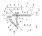
- the base body 12 after Fig. 3 further has a third channel 356, in which a long lamp 358 is attached and arranged for illuminating adjacent storage devices.
- the base body 12 is designed to be attachable to the storage device 312 of the system 10 via a claw-like area 360.
- the final device 14 (cf. Fig. 4 ) of the power supply system 352 with the base body 12 according to the Fig. 3 has a flat body 40 made of a plastic material with two opposite sides 42 and 44 and an insert body 46 made of a plastic material connected to the side 42.
- the plug-in body 46 can be received in a non-positive manner in the channel 16 by inserting it into the channel 16 at the end.
- the supply line end sections 38 which can be contacted with the respective current conductor end sections of the channel 16, are on the plug-in body 46 is provided, wherein in this exemplary embodiment both the upper and lower supply line end sections 38 are each designed in the form of a double contact.
- the termination device 14 according to FIG. 9 also has a second and a third insertion body 112, 114.
- the second plug-in body 112 has two supply line end sections 328 in the form of contacting elements 328 for the power supply of the signaling devices 309, which can be contacted with respective busbar conductors by inserting the plug-in body 112 into the channel 314.
- the contacting elements 328 themselves are in turn electrically connected to a line, which is partially accommodated in a sheathing of a cable 117, in which the supply lines for powering the display devices 11 and the long lamp 358 are also partially accommodated.
- the second plug-in body 112 also has a connection device 362 of a signal transmission line, which is also accommodated in sections in the sheathing of the cable 117
- the third plug-in body 114 has two connection elements 118 for the power supply of the long lamp 358, which can be contacted with supply lines, not shown, of the long lamp 358, which are arranged in the channel 356, by inserting the plug-in body 112 into the channel 356.
- the connection elements 118 themselves are in turn electrically connected to a line, which is partially in the sheathing of the cable 117 is recorded.
- all of the supply lines accommodated in sections in the sheathing of the cable 117 can be energized via respective connection elements provided on at least one holding element by receiving the holding element in the respective receptacle of the holding post, namely to power the display devices 11, the signaling devices 309 and the long lamp 358.
- the respective end face of the base body 12 can be covered by the flat body 40 of the termination device 14 by inserting the insert body 46 and the insert bodies 112 and 114 into the channels 16, 314 and 356 at the end.
- the product presentation system 66 after Fig. 5 comprises a system 10 according to the invention with the storage device 312 and a goods shelf 308 with two holding posts 68, although in alternative embodiments a higher number of holding posts and storage devices can of course also be provided.
- the storage device 312 has the storage element 306 with the storage surface 304 and two holding elements 76.
- the holding elements 76 are detachably connected to the storage element 306, namely through receptacles, not shown, on the storage element 306, into which tabs of the holding elements 76, not shown, can be inserted.
- Each holding post 68 has four receptacles 78, with one of the holding elements 76 for holding the storage device 70 on the holding post 68 being receivable in each of the receptacles 78.
- the Fig. 5 already illustrates the state in which the holding elements 76 are accommodated in one of two opposing receptacles 78, one receptacle 78 being located on one holding post 68 and the other receptacles 78 being located on the other holding post 68.
- One of the two holding posts 68 has two electrical conductors 80 which are intended for connection to a power source 82.
- One of the holding elements 76 has two electrical connection elements 84, one of the supply lines 32, 34, 324, 326 of the termination device 14 being able to be connected to each connection element 84 in an electrically conductive manner.
- connection element 84 can be contacted in an electrically conductive manner with one of the conductors 80 of the holding post 68 by receiving the holding element 76 in the respective receptacle 78 of the holding post 68.
- the elongated base body 12 of the system 10 can be attached to the storage device 312, whereby the Fig. 4 already illustrates the appropriate condition.
- the storage element 306 is elongated and the elongated base body 12 can be attached to the storage device 312 in an arrangement in which a surface 90 of the base body 12 extending along the longitudinal axis 86 of the base body 12 is a surface extending along the longitudinal axis 88 of the storage element 306 91 of the storage element 306 faces.
- the product presentation system 66 after Fig. 6 differs from the product presentation system 66 Fig. 5 in that the holding post 68 additionally has a signal line 92 which is provided for transmitting signals from the signaling device(s) 309 to a signal processing device (336).
- the holding element 76 with the electrical connection elements 84 additionally has a signal line connection 96, wherein a signal transmission line 334 of the termination device 14 of the power supply system 352 can be connected to the signal line connection 96.
- the signal line connection 96 can be connected in a signal-transferable manner to the signal line 92 of the holding post 68 by receiving the holding element 76 in the receptacle 78 of the holding post 68.
Description
Die vorliegende Erfindung betrifft ein System umfassend wenigstens eine Einrichtung, wenigstens eine Ablagevorrichtung für ein Warenregal und ein Bestromungssystem zur Bestromung mehrerer elektronischer Anzeigeeinrichtungen zur Anzeige von warenbezogenen Informationen, wobei die Einrichtung mit einem Flachelement aus einem Kunststoffmaterial und mit einer Signalisierungseinrichtung ausgestaltet ist.The present invention relates to a system comprising at least one device, at least one storage device for a goods shelf and a power supply system for powering several electronic display devices for displaying goods-related information, the device being designed with a flat element made of a plastic material and with a signaling device.
Bekannte Warenerfassungssysteme sind z.B. aus den folgenden Internetquellen bekannt:
-
Panasonic: "NRF Big Show 2015 Panasonic Introduces Intelligent Retail Shelving Solution at NRF 2015 Powershelf Combines Live on Shelf Inventory Awareness, Mobile Phone Advertising, Dynamic Price Adjustments and More to Improve Profitability and Customer Satisfaction - , 11. Januar 2015 (2015-01-11), Seiten 1-4, XP055458103, Gefunden im Internet:
- URL:https://www.businesswire.com/news/home/ 20150111005029/en/Panasonic-Introduces-Intelligent-Retail-Shelving-Solution-NRF
- [gefunden am 2018-03-09] ; & Powersheif: "Powershelf | Power
- at the Shelf",
-
2. Februar 2015 (2015-02-02), Seiten 1-13, XP055458107 - URL:http://powershelf.net/wordpress/
- [gefunden am 2018-03-09]
-
Panasonic: "NRF Big Show 2015 Panasonic Introduces Intelligent Retail Shelving Solution at NRF 2015 Powershelf Combines Live on Shelf Inventory Awareness, Mobile Phone Advertising, Dynamic Price Adjustments and More to Improve Profitability and Customer Satisfaction - , January 11, 2015 (2015-01-11), pages 1-4, XP055458103, Found on the Internet:
- URL: https://www.businesswire.com/news/home/ 20150111005029/en/Panasonic-Introduces-Intelligent-Retail-Shelving-Solution-NRF
- [found on 2018-03-09] ; & Powersheif: "Powershelf | Power
- at the Shelf",
-
February 2, 2015 (2015-02-02), pages 1-13, XP055458107 - URL: http://powershelf.net/wordpress/
- [found on 2018-03-09]
Aus der
Im Einzelhandel, insbesondere in Supermärkten und Drogeriemärkten, ist der Einsatz von elektronischen bzw. computerbasierten Warenerfassungssystemen gängige Praxis. Warenerfassungssysteme verarbeiten als eine wesentliche Eingangsgröße insbesondere den bestehenden Warenbestand, welcher in der Regel - z.B. im Rahmen einer Inventur- technisch sehr aufwendig und auch meist sehr personalintensiv durch Erfassen der auf den Ablagevorrichtungen bzw. Regalböden der Warenregale angeordneten bzw. abgelegten Waren ermittelt werden muss. Ein zu unterschiedlichen Zeitpunkten ermittelter Warenbestand ist auch eine wesentliche Eingangsgröße zur Ermittlung des warenbezogenen Kaufverhaltens der potentiellen Käufer bzw. Kunden. Konkret kann so z.B. festgestellt werden, inwieweit sich die Nachfrage für eine bestimme Ware mit der Zeit ändert. Allerdings ist auch die Ermittlung des Kaufverhaltens insbesondere infolge der hierfür erforderlichen personalintensiven und technisch sehr aufwendigen Ermittlung des Warenbestands sehr personalintensiv und technisch sehr aufwendig.In retail, especially in supermarkets and drugstores, the use of electronic or computer-based goods registration systems is common practice. Goods registration systems process this as an essential input variable existing inventory of goods, which usually - for example as part of an inventory - has to be determined in a technically very complex and also usually very labor-intensive manner by recording the goods arranged or stored on the storage devices or shelves of the goods shelves. An inventory of goods determined at different times is also an important input variable for determining the product-related purchasing behavior of potential buyers or customers. Specifically, for example, it can be determined to what extent the demand for a certain product changes over time. However, the determination of purchasing behavior is also very personnel-intensive and technically very complex, particularly due to the labor-intensive and technically very complex determination of the inventory.
Der vorliegenden Erfindung liegt daher die Aufgabe zugrunde, ein System mit einer Einrichtung anzugeben, das dazu beitragen kann, den Aufwand zur Ermittlung eines warenbezogenen Kaufverhaltens deutlich zu reduzieren.The present invention is therefore based on the object of specifying a system with a device that can help to significantly reduce the effort required to determine product-related purchasing behavior.
Diese Aufgabe wird erfindungsgemäß mit einem nachfolgend beschriebenen System gelöst.This object is achieved according to the invention with a system described below.
Die Einrichtung des erfindungsgemäßen Systems umfasst ein Flachelement beispielsweise aus einem Kunststoffmaterial zum Anordnen bzw. Ablegen auf einer Ablagefläche eines Ablageelements für ein Warenregal bzw. eines Warenregals und wenigstens eine elektrische Signalisierungseinrichtung bzw. Signalisisierungseinrichtung zum Signalisieren einer Gewichtsbelastung wenigstens eines Bereichs des Flachelements durch wenigstens eine auf dem Flachelement angeordnete bzw. abgelegte Ware bzw. durch wenigstens eine auf einer Flachseite des Flachelement angeordneten bzw. abgelegen Ware. Bei der elektrischen Signalisierungseinrichtung bzw. bei der Signalisisierungseinrichtung, die zum Signalisieren einer Gewichtsbelastung wenigstens eines Bereichs des Flachelements durch wenigstens eine auf dem Flachelement angeordnete bzw. abgelegte Ware vorgesehen ist, handelt es sich also um eine elektrische Signalisierungseinrichtung bzw. um eine Signalisisierungseinrichtung zum Signalisieren einer Gewichtsbelastung wenigstens eines Bereichs des Flachelements durch wenigstens eine auf dem Flachelement angeordnete Ware bzw. zum Signalisieren einer auf wenigstens einen Bereichs des Flachelements durch wenigstens eine auf dem Flachelement angeordnete Ware übertragene Gewichtskraft.The device of the system according to the invention comprises a flat element, for example made of a plastic material, for arranging or depositing on a storage surface of a storage element for a goods shelf or a goods shelf and at least one electrical signaling device or signaling device for signaling a weight load of at least one area of the flat element by at least one goods arranged or placed on the flat element or by at least one goods arranged or placed on a flat side of the flat element. The electrical signaling device or the signaling device, which is provided for signaling a weight load on at least one area of the flat element by at least one item arranged or placed on the flat element, is therefore an electrical signaling device or a signaling device for signaling a Weight loading of at least one area of the flat element by at least one product arranged on the flat element or for signaling a weight force transmitted to at least one area of the flat element by at least one product arranged on the flat element.
Das Flachelement ist hierbei unter Ausbildung wenigstens eines flächigen Kontakts einer der beiden Flachseiten des Flachelements zur der Ablagefläche auf dieser anordenbar bzw. ablegbar. Als Flachelement weist es eine Dicke bzw. Dickenerstreckung auf, die kleiner bzw. wesentlich kleiner ausgebildet ist als die Länge oder die Breite des Flachelements.The flat element can be arranged or placed on the storage surface to form at least one flat contact between one of the two flat sides of the flat element and the storage surface. As a flat element, it has a thickness or thickness extension that is smaller or significantly smaller than the length or width of the flat element.
Die Einrichtung kann dazu beitragen, den Aufwand zur Ermittlung eines warenbezogenen Kaufverhaltens deutlich zu reduzieren. So kann die Einrichtung derart für die Ermittlung des Kaufverhaltens verwendet werden bzw. zu dieser beitragen, in dem das Flachelement auf einer Ablagefläche eines Ablageelements eines Warenregals des jeweiligen Verkaufsraums (wie z.B. einem Verkaufsraum eines Supermarkts oder Drogeriemarkts) angeordnet bzw. abgelegt wird und anschließend eine oder mehrere zum Verkauf anzubietende Waren auf dem Fachelement abgelegt bzw. angeordnet werden. Die mit der Ablage bzw. Anordnung einhergehende Gewichtsbelastung des Flachelements wird - sofern die Ware bzw. Waren auf einem Bereich abgelegt wurde bzw. wurden, bei dem die Signalisierungseinrichtung eine Gewichtsbelastung durch die Ware bzw. Waren signalisieren kann - von der Signalisierungseinrichtung signalisiert, wobei die Signalisierung einer bestehenden Gewichtsbelastung besonders bevorzugt durch ein von der Signalisierungseinrichtung ausgegebenes Signal bzw. elektrisches Signal erfolgt, das also über die Gewichtsbelastung informiert. Typischerweise könnte dieses Signal ein von einer Signalerzeugungseinrichtung der Signalisierungseinrichtung erzeugtes bzw. erzeugbares Signal sein oder ein von einem Signalgeber der Signalisierungseinrichtung erzeugtes bzw. erzeugbares Signal sein. Dieses Signal bzw. elektrische Signal könnte besonders praktisch z.B. in Form eines Rechtecksignals ausgebildet sein. Es versteht sich, dass es sich bei dem Signal insbesondere auch um ein durch Analog/Digital-Wandlung erzeugtes digitales Signal handeln kann, welches sich vorteilhaft mittels eines Computers bzw. einer Datenverarbeitungseinrichtung eines Warenerfassungssystems z.B. des Supermarkts oder z.B. des Drogeriemarkts weiter verarbeiten lässt. Die Dauer bzw. Dauern des bzw. der Zeitabschnitte eines vorgegebenen Zeitraums, bei dem bzw. denen ein die Gewichtsbelastung kennzeichnendes Signal auftritt bzw. vorliegt können in Verbindung mit der Dauer bzw. den Dauern des Zeitabschnitts bzw. der Zeitabschnitte des vorgegebenen Zeitraums, bei denen dieses Signal ausbleibt, vorteilhaft als Information bzw. verwertbare Information für die Ermittlung des warenbezogenen Kaufverhaltens herangezogen werden. Insbesondere können die Dauern dieser Zeitabschnitte - nach einer ggf. erforderlichen Digitalisierung der Dauern - vorteilhaft insbesondere für eine computerbasierte Ermittlung des warenbezogenen Kaufverhaltens mittels dem Fachmann geläufiger Verfahren bzw. Methoden verwendet werden. Die Verwertbarkeit dieser Zeitabschnitte für das Kaufverhalten ergibt sich z.B. aus dem Umstand, dass bei den Zeitabschnitten mit dem die Gewichtsbelastung kennzeichnenden Signal bzw. Signalen sich die Ware bzw. die Waren auf dem Flachelement befindet bzw. befinden und bei den Zeitabschnitten, bei denen das die Gewichtsbelastung kennzeichnende Signal ausbleibt, keine Ware auf dem Flachelement mehr vorhanden ist, weil sie z.B. vom Kunden weggenommen wurde.The facility can help to significantly reduce the effort required to determine product-related purchasing behavior. The device can be used to determine purchasing behavior or contribute to this in that the flat element is arranged or placed on a storage surface of a storage element of a goods shelf in the respective sales area (such as a sales area in a supermarket or drugstore) and then a or several goods to be offered for sale are placed or arranged on the compartment element. The weight load on the flat element associated with the storage or arrangement is - if the goods or goods have been placed on an area in which the signaling device can signal a weight load caused by the goods or goods - signaled by the signaling device, whereby the Signaling of an existing weight load particularly preferably by a signal output by the signaling device or electrical signal occurs, which provides information about the weight load. Typically, this signal could be a signal generated or capable of being generated by a signal generating device of the signaling device or a signal generated or capable of being generated by a signal generator of the signaling device. This signal or electrical signal could be particularly practical, for example in the form of a square wave signal. It is understood that the signal can in particular also be a digital signal generated by analog/digital conversion, which can advantageously be further processed using a computer or a data processing device of a goods registration system, for example in a supermarket or, for example, in a drugstore. The duration or durations of the time period or periods of a predetermined period of time in which a signal characterizing the weight load occurs or is present can be combined with the duration or durations of the time period or periods of the predetermined period of time in which If this signal is missing, it can advantageously be used as information or usable information for determining product-related purchasing behavior. In particular, the durations of these time periods - after any necessary digitization of the durations - can be used advantageously, in particular, for a computer-based determination of product-related purchasing behavior using procedures or methods familiar to those skilled in the art. The usability of these time periods for purchasing behavior results, for example, from the fact that in the time periods with the signal or signals characterizing the weight load, the product or goods are located on the flat element and in the time periods in which the The signal indicating the weight load is missing and there are no goods left on the flat element, for example because they were taken away by the customer.
Es versteht sich, dass die Signalisisierungseinrichtung nicht dazu eingerichtet sein muss, den Wert bzw. genauen Wert der jeweiligen Gewichtsbelastung zu messen. Es ist lediglich erforderlich, dass die Signalisisierungseinrichtung feststellt, dass eine Gewichtsbelastung vorliegt, was typischerweise z.B. bei Messung einer eine Belastungsschwelle überschreitenden Belastung mittels eines Gewichtskraftmesseinrichtung der Signalisierungseinrichtung der Fall ist.It goes without saying that the signaling device does not have to be set up to measure the value or exact value of the respective weight load. It is only necessary that the signaling device determines that a weight load is present, which is typically the case, for example, when measuring a load that exceeds a load threshold using a weight force measuring device of the signaling device.
Insgesamt betrachtet kann die Verwendung der erfindungsgemäßen Einrichtung bzw. die Verwendung einer Mehrzahl der erfindungsgemäßen Einrichtungen dazu beitragen, den Aufwand zur Ermittlung eines warenbezogenen Kaufverhaltens gegenüber den bekannten Lösungen deutlich zu reduzieren, da über die ermöglichte Signalisierung der Gewichtsbelastung des Flachelements durch die Ware bzw. Waren ohne großen Personalaufwand und auch ohne großen technischen Aufwand insbesondere eine computergestützte Ermittlung des warenbezogenen Kaufverhaltens möglich ist. Beispielsweise kann aus dem Signalisieren einer Gewichtsbelastung durch das die Gewichtsbelastung kennzeichnende Signal und einem anschließenden Ausbleiben des die Gewichtsbelastung kennzeichnenden Signals für mehr als eine Minute mit hoher Wahrscheinlichkeit darauf geschlossen werden, dass die Ware von dem Kunden auch gekauft werden will. Tritt das die Gewichtsbelastung kennzeichnende Signal schon früher wieder auf, kann mit hoher Wahrscheinlichkeit darauf geschlossen werden, dass die Ware von dem Kunden zurückgestellt wurde und kein Kaufinteresse besteht.Overall, the use of the device according to the invention or the use of a plurality of the devices according to the invention can contribute to reducing the effort required to determine product-related purchasing behavior compared to the known ones Solutions can be significantly reduced, since the enabled signaling of the weight load on the flat element by the goods or goods makes it possible, in particular, to computer-aided determination of the goods-related purchasing behavior without a lot of personnel effort and also without a lot of technical effort. For example, from the signaling of a weight load by the signal characterizing the weight load and a subsequent absence of the signal characterizing the weight load for more than a minute, it can be concluded with a high degree of probability that the customer actually wants to buy the product. If the signal indicating the weight load occurs again earlier, it can be concluded with high probability that the goods have been put back by the customer and there is no interest in purchasing them.
Aufgrund des oben Dargelegten versteht es sich auch, dass die Einrichtung insbesondere auch vorteilhaft für die Ermittlung des Warenbestands der auf dem Flachelement abgelegten Ware bzw. Waren verwendet werden kann, und zwar kann der Warenbestand gegenüber den bekannten Lösungen aufgrund des oben Dargelegten gegenüber den bekannten Lösungen mit einem deutlich geringeren Aufwand bewerkstelligt werden, insbesondere kann mittels der erfindungsgemäßen Einrichtung für die Warenbestandsermittlung erforderliches Personal eingespart werden. Insofern löst die Einrichtung auch die Aufgabe, den Aufwand zur Ermittlung eines Warenbestands eines Warenregals deutlich zu reduzieren. Insbesondere betrifft die Erfindung daher auch die Verwendung der Einrichtung für die Ermittlung eines Warenbestands eines Warenregals.Based on what has been stated above, it is also understood that the device can also be used in particular advantageously for determining the inventory of the goods or goods placed on the flat element, namely the inventory of goods can be compared to the known solutions due to what has been stated above compared to the known solutions can be accomplished with significantly less effort, in particular the personnel required for inventory determination can be saved using the device according to the invention. In this respect, the device also solves the task of significantly reducing the effort required to determine the inventory of a goods shelf. In particular, the invention therefore also relates to the use of the device for determining an inventory of goods on a goods shelf.
Vorteilafterweise kann die Einrichtung insbesondere auch eine Mehrzahl von Signalisierungseinrichtungen aufweisen, wobei jede der Signalisierungseinrichtungen vorzugsweise eine Gewichtsbelastung eines ihr zugeordneten Bereichs des Flachelements durch wenigstens eine Ware signalisiert bzw. signalisieren kann. Auf diese Weise kann für das jeweilige Ablageelement das Kaufverhalten bzw. der Warenbestand für eine Vielzahl von auf dem jeweiligen Ablageelement abgelegten Waren überwacht werden. Besonders praktisch können, sofern die Signalisierungseinrichtungen zur Ausgabe von Signalen eingerichtet sind, die von den jeweiligen Signalisierungseinrichtungen ausgegebenen bzw. erzeugten Signale nach einer ggf. erforderlichen Analog/Digital-Wandlung über einen Computer verarbeitet werden, der auf der Grundlage der an ihn übertragenen Signale bzw. Daten den Warenbestand bzw. das Kaufverhalten in dem Fachmann geläufiger Weise über eine an den Computer angeschlossene Anzeigeeinrichtung, wie z.B. einen großen zentralen Bildschirm in einem Managementraum eines Kaufhauses, darstellt bzw. veranschaulicht.Advantageously, the device can in particular also have a plurality of signaling devices, each of the signaling devices preferably signaling or being able to signal a weight load on an area of the flat element assigned to it by at least one product. In this way, the purchasing behavior or the inventory of goods for a large number of goods stored on the respective storage element can be monitored for the respective storage element. Particularly practical, if the signaling devices are set up to output signals, the signals output or generated by the respective signaling devices can be processed after any necessary analog/digital conversion via a computer, which is based on the signals or .Data the inventory or purchasing behavior in a manner familiar to those skilled in the art via a Computer connected display device, such as a large central screen in a management room of a department store.
Besonders praktisch kann die Signalisierungseinrichtung bzw. die jeweilige Signalisierungseinrichtung eine Meldeeinrichtung aufweisen und dazu eingerichtet sein, bei Vorliegen oder Nicht-Vorliegen einer bestehenden Gewichtsbelastung des Flachelements durch wenigstens eine Ware die Meldeeinrichtung zwecks Meldung der Gewichtsbelastung oder der nicht vorliegenden Gewichtsbelastung anzusteuern. Die Meldung könnte z.B. durch Erleuchtung eines Leuchtmittels der Meldeeinrichtung realisiert sein.Particularly practical, the signaling device or the respective signaling device can have a reporting device and can be set up to control the reporting device for the purpose of reporting the weight load or the absence of weight load in the presence or absence of an existing weight load on the flat element by at least one item. The message could be realized, for example, by illuminating a lamp in the signaling device.
Die Signalisisierungseinrichtung zum Signalisieren einer Gewichtsbelastung wenigstens eines Bereichs des Flachelements durch wenigstens eine auf dem Flachelement angeordnete Ware weist besonders bevorzugt wenigstens einen Kraftsensor zur Messung der Gewichtsbelastung auf, der an dem Flachelement angeordnet bzw. angebracht ist.The signaling device for signaling a weight load of at least one area of the flat element by at least one product arranged on the flat element particularly preferably has at least one force sensor for measuring the weight load, which is arranged or attached to the flat element.
Bei dem Kraftsensor handelt es sich um einen Kraftsensor zur Messung bzw. zur elektrischen Messung einer auf den Kraftsensor einwirkenden Gewichtskraft bzw. zur Messung bzw. elektrischen Messung einer Gewichtsbelastung des Kraftsensors, wobei die Messfläche des Kraftsensors, über welche die zu messende Gewichtskraft in den Kraftsensor zur Messung derselben einzuleiten ist bzw. über welche die zu messende Gewichtskraft auf den Kraftsensor zu übertragen ist, eine Anordnung in Bezug auf das Flachelement aufweist, bei welcher eine Gewichtsbelastung des Flachelements durch eine oder mehrere Waren durch den Kraftsensor messbar ist. Dies bedeutet, dass die Messfläche des Kraftsensors besonders bevorzugt parallel bzw. besonders bevorzugt im Wesentlichen parallel zu einer der beiden Flachseiten des Flachelements angeordnet ist. Der Kraftsensor kann insbesondere derart an dem Flachelement angebracht sein, dass sich die Messfläche des Kraftsensors im auf die Ablagefläche des Ablageelements aufgelegten Zustand des Flachelements über dem Flachelement oder zwischen dem Flachelement und der Ablagefläche des Ablageelements befindet. Besonders bevorzugt kann die Signalisierungseinrichtung auch teilweise in das Kunststoffmaterial des Flachelements derart eingebettet sein, dass die Messfläche des Kraftsensors in das Kunststoffmaterial des Flachelements eingebettet ist bzw. dass die Messfläche des Kraftsensors in dem Kunststoffmaterial aufgenommen ist, wobei das Kunststoffmaterial besonders bevorzugt aus einem Thermoplasten, wie beispielsweise Polypropylen oder Polyethylen, besteht, um eine wirksame Kraftübertragung der Gewichtskraft durch das Kunststoffmaterial des Flachelements hindurch auf die Messfläche des Kraftsensors realisieren zu können. Bei dem Kraftsensor kann es sich um einen dem Fachmann geläufigen Kraftsensor handeln. So kann es sich z.B. um einen Kraftsensor mit Dehnungsmessstreifen oder z.B. um einen Piezo-Kraftsensor bzw. einen piezoelektrischen Kraftsensor oder z.B. um einen resistiven Kraftsensor handeln.The force sensor is a force sensor for measuring or electrically measuring a weight force acting on the force sensor or for measuring or electrically measuring a weight load on the force sensor, the measuring surface of the force sensor via which the weight force to be measured enters the force sensor to be initiated to measure the same or via which the weight force to be measured is to be transmitted to the force sensor, has an arrangement in relation to the flat element, in which a weight load on the flat element caused by one or more goods can be measured by the force sensor. This means that the measuring surface of the force sensor is particularly preferably arranged parallel or particularly preferably substantially parallel to one of the two flat sides of the flat element. The force sensor can in particular be attached to the flat element in such a way that the measuring surface of the force sensor is located above the flat element or between the flat element and the storage surface of the storage element when the flat element is placed on the storage surface of the storage element. Particularly preferably, the signaling device can also be partially embedded in the plastic material of the flat element in such a way that the measuring surface of the force sensor is embedded in the plastic material of the flat element or that the measuring surface of the force sensor is accommodated in the plastic material, the plastic material particularly preferably made of a thermoplastic, such as polypropylene or polyethylene, exists to ensure effective power transmission to be able to realize the weight force through the plastic material of the flat element onto the measuring surface of the force sensor. The force sensor can be a force sensor familiar to those skilled in the art. For example, it can be a force sensor with strain gauges or, for example, a piezo force sensor or a piezoelectric force sensor or, for example, a resistive force sensor.
Die Signalisierung einer bestehenden Gewichtsbelastung des Flachelements kann, wie bereits oben dargelegt, besonders bevorzugt durch ein von der Signalisierungseinrichtung ausgegebenes Signal erfolgen, das also über die Gewichtsbelastung informiert. Typischerweise könnte dieses Signal ein von einer Signalerzeugungseinrichtung der Signalisierungseinrichtung erzeugtes bzw. erzeugbares Signal sein oder ein von einem Signalgeber der Signalisierungseinrichtung erzeugtes bzw. erzeugbares Signal sein, wobei die Signalerzeugungseinrichtung bzw. der Signalgeber dieses Signal vorzugsweise aus dem von dem Kraftsensor ausgegeben Messsignal erzeugt bzw. bildet bzw. auf der Grundlage des von dem Kraftsensor ausgegeben Messsignals erzeugt bzw. bildet. Dieses elektrische Signal könnte besonders praktisch z.B. in Form eines Rechtecksignals ausgebildet sein, das z.B. bei Überschreitung oder Unterschreitung eines Signal-Schwellwertes des Messsignals des Kraftsensors von der Signalerzeugungseinrichtung erzeugbar sein kann.The signaling of an existing weight load on the flat element can, as already explained above, particularly preferably take place by a signal issued by the signaling device, which therefore provides information about the weight load. Typically, this signal could be a signal generated or capable of being generated by a signal generating device of the signaling device or a signal generated or capable of being generated by a signal generator of the signaling device, the signal generating device or signal generator preferably generating or generating this signal from the measurement signal output by the force sensor. forms or generates or forms based on the measurement signal output by the force sensor. This electrical signal could be particularly practical, for example in the form of a square-wave signal, which can be generated by the signal generating device when a signal threshold value of the measurement signal from the force sensor is exceeded or fallen below.
Bei der Signalisisierungseinrichtung handelt es sich um eine Signalisisierungseinrichtung zum Signalisieren einer Gewichtsbelastung wenigstens eines Bereichs des Flachelements durch wenigstens eine auf dem Flachelement angeordnete Ware. Besonders vorteilhaft kann es sich bei der Signalisisierungseinrichtung um eine Signalisisierungseinrichtung handeln, die dazu eingerichtet ist, eine Gewichtskraft zu signalisieren, die über eine beliebige Teilfläche einer der Flachseiten des Flachelements von wenigstens einer Ware auf das Flachelement übertragen wird. Dies kann besonders praktisch derart erfolgen, dass die Signalisisierungseinrichtung einen Kraftsensor zur Messung der Gewichtsbelastung mit einer Messfläche aufweist, die der Flächengröße der Flachseite entspricht oder größer als diese ausgebildet ist.The signaling device is a signaling device for signaling a weight load on at least one area of the flat element by at least one product arranged on the flat element. Particularly advantageously, the signaling device can be a signaling device which is set up to signal a weight force which is transmitted from at least one product to the flat element via any partial area of one of the flat sides of the flat element. This can be done particularly practically in such a way that the signaling device has a force sensor for measuring the weight load with a measuring area that corresponds to the area size of the flat side or is larger than this.
Bei der Ablagefläche des Ablageelements handelt es sich um eine Ablagefläche zum Ablegen bzw. Anordnen von wenigstens einer Ware, auf welcher erfindungsgemäß anstelle der Ware bzw. Waren das Flachelement aufzulegen bzw. flächig aufzulegen ist. Auf das Flachelement ist wiederum die wenigstens eine Ware zum Zwecke der Ermittlung des warenspezifischen Kaufverhaltens bzw. des warenspezifischen Warenbestands aufzulegen bzw. anzuordnen.The storage surface of the storage element is a storage surface for storing or arranging at least one product, on which, according to the invention, the flat element is to be placed or laid flat instead of the product or goods. On the flat element In turn, the at least one product must be placed or arranged for the purpose of determining the product-specific purchasing behavior or the product-specific inventory.
Bei einer besonders bevorzugten Ausführungsform der Einrichtung ist das Flachelement länglich ausgebildet und die Einrichtung weist mehrere Signalisierungseinrichtungen mit jeweils einem Kraftsensor auf, wobei die Messflächen der Signalisierungseinrichtungen in Längsrichtung des Flachelements besonders bevorzugt reihenförmig aufeinanderfolgend angeordnet sind. Durch eine reihenförmige Anordnung der Kraftsensoren wird vorteilhaft eine Signalisierungsmöglichkeit über bestehende Gewichtsbelastungen von aufgelegten Waren über die gesamte Länge des Flachelements realisiert. Insbesondere kann durch die reihenförmige Anordnung jeweils eine Signalisierungseinrichtung für jeweils einen Abschnitt des Flachelements vorgesehen sein, und mithin kann also jede Signalisierungseinrichtung für wenigstes eine auf dem jeweiligen Abschnitt ggf. angeordnete Ware vorgesehen sein bzw. eine Gewichtsbelastung signalisieren. Insgesamt betrachtet kann mittels dieser Ausbildung vorteilhaft für eine große Mehrzahl von Waren ohne großen Aufwand eine warenspezifische Signalisierung der Gewichtsbelastungen realisiert werden.In a particularly preferred embodiment of the device, the flat element is elongated and the device has a plurality of signaling devices, each with a force sensor, the measuring surfaces of the signaling devices particularly preferably being arranged in rows one after the other in the longitudinal direction of the flat element. By arranging the force sensors in rows, a signaling option about existing weight loads of placed goods over the entire length of the flat element is advantageously realized. In particular, due to the row-shaped arrangement, a signaling device can be provided for each section of the flat element, and therefore each signaling device can be provided for at least one product that may be arranged on the respective section or can signal a weight load. Overall, this design can advantageously be used to implement goods-specific signaling of the weight loads for a large number of goods without much effort.
Die obige Aufgabe - bzw. die obigen Aufgaben - wird/werden gelöst durch ein erfindungsgemäßes System umfassend wenigstens eine Einrichtung, wenigstens eine Ablagevorrichtung für ein Warenregal und ein Bestromungssystem zur Bestromung mehrerer elektronischer Anzeigeeinrichtungen zur Anzeige von warenbezogenen Informationen, wobei die Ablagevorrichtung ein Ablageelement mit einer Ablagefläche aufweist, auf welcher das Flachelement auflegbar ist, wobei das Bestromungssystem einen an der Ablagevorrichtung anbringbaren länglichen Grundkörper aus einem Kunststoffmaterial und wenigstens eine Abschlusseinrichtung aufweist, wobei der Grundkörper einen sich über die gesamte Länge des Grundkörpers erstreckenden Kanal zur Aufnahme der Anzeigeeinrichtungen aufweist, wobei der Grundkörper zwei entgegengesetzte Endabschnitte aufweist, wobei jeder der Endabschnitte einen von zwei entgegengesetzten Kanal-Endabschnitten des Kanals aufweist, wobei die Anzeigeeinrichtungen in dem Kanal aufnehmbar sind, wobei das Bestromungssystem wenigstens zwei Stromleiter aufweist, wobei jeder der Stromleiter zwei Stromleiter-Endabschnitte und einen Zwischenabschnitt aufweist, wobei der Zwischenabschnitt jedes Stromleiters in dem Kanal angeordnet ist und von jedem Stromleiter jeweils einer der Stromleiter-Endabschnitte in jeweils einem der beiden entgegengesetzten Kanal-Endabschnitte mit wenigstens einem Teilabschnitt angeordnet ist, wobei durch Aufnehmen der Anzeigeeinrichtungen in dem Kanal jeweils ein Stromversorgungskontakt jeder Anzeigeeinrichtung mit jeweils einem der Stromleiter elektrisch leitend kontaktierbar ist, wobei die Abschlusseinrichtung wenigstens zwei elektrische Versorgungsleitungen aufweist, die zum Herstellen einer Verbindung mit einer Stromquelle vorgesehen sind, wobei die Abschlusseinrichtung mit wenigstens einem der beiden entgegengesetzten Endabschnitte des Grundkörpers verbindbar ist, wobei durch Verbinden der Abschlusseinrichtung mit dem Endabschnitt des Grundkörpers jeweils ein Versorgungsleitungs-Endabschnitt jeder der Versorgungsleitungen mit jeweils einem Stromleiter-Endabschnitt der Stromleiter-Endabschnitte elektrisch leitend kontaktierbar ist, die in dem Kanal-Endabschnitt des Endabschnitts des Grundkörpers mit wenigstens einem Teilabschnitt angeordnet sind, also dem Endabschnitt des Grundkörpers mit welchem die Abschlusseinrichtung verbunden wird bzw. werden soll.The above task - or the above tasks - is / are solved by a system according to the invention comprising at least one device, at least one storage device for a goods shelf and a power supply system for powering several electronic display devices for displaying goods-related information, the storage device having a storage element with a Has a storage surface on which the flat element can be placed, the power supply system having an elongated base body made of a plastic material that can be attached to the storage device and at least one closing device, the base body having a channel extending over the entire length of the base body for receiving the display devices, the Base body has two opposite end sections, each of the end sections having one of two opposite channel end sections of the channel, the display devices being receivable in the channel, the current supply system having at least two current conductors, each of the current conductors having two current conductor end sections and an intermediate section , wherein the intermediate section of each current conductor is arranged in the channel and one of the current conductor end sections of each current conductor is arranged in one of the two opposite channel end sections with at least one partial section, wherein by accommodating the display devices in the channel, a power supply contact of each display device can be contacted in an electrically conductive manner with one of the current conductors, the termination device having at least two electrical supply lines which are provided for establishing a connection to a power source, the termination device having at least one of the both opposite end sections of the base body can be connected, wherein by connecting the termination device to the end section of the base body, a supply line end section of each of the supply lines can be electrically contacted with a respective current conductor end section of the current conductor end sections, which is in the channel end section of the end section of the Base body are arranged with at least one section, i.e. the end section of the base body with which the termination device is or should be connected.
Bei dem länglichen Grundkörper aus einem Kunststoffmaterial handelt es sich besonders bevorzugt um einen extrudierten Grundköper bzw. einem im Wege der Extrusion hergestellten Grundkörper. Derartige Grundkörper sind kostengünstig in großer Vielzahl und hoher gleichbleibender Qualität herstellbar. Als Material hierfür eignen sich thermoplastische Kunststoffmaterialien, wie beispielsweise Polypropylen oder Polyethylen.The elongated base body made of a plastic material is particularly preferably an extruded base body or a base body produced by extrusion. Such base bodies can be produced cost-effectively in a large variety and of high, consistent quality. Suitable materials for this are thermoplastic materials, such as polypropylene or polyethylene.
Bei dem länglichen Grundkörper aus einem Kunststoffmaterial zum Anbringen an der Ablagevorrichtung bzw. Abstellvorrichtung für das Warenregal bzw. des Warenregals handelt es sich also um einen länglichen Grundkörper, der zum Anbringen an der Ablagevorrichtung vorgesehen ist bzw. welcher an der Ablagevorrichtung anbringbar bzw. mit dieser Ablagevorrichtung verbindbar ist. Die Ablagevorrichtung kann hierbei insbesondere einen Regalboden eines Warenregals bzw. für ein Warenregal umfassen bzw. in Form eines Regalbodens eines Warenregals bzw. für ein Warenregal ausgebildet sein. Zum Halten des Grundkörpers an der Ablagevorrichtung kann der Grundkörper z.B. wenigstens einen Bereich aufweisen, der in einer an der Ablagevorrichtung vorgesehenen Aufnahme aufnehmbar ist. Der wenigstens eine Bereich kann z:b auch ein hakenförmiger Bereich sein, der in eine an Ablagevorrichtung vorgesehene Aufnahme einhängbar ist.The elongated base body made of a plastic material for attachment to the storage device or storage device for the goods shelf or the goods shelf is therefore an elongated base body which is intended for attachment to the storage device or which can be attached to or with the storage device Storage device can be connected. The storage device can in particular comprise a shelf of a goods shelf or for a goods shelf or can be designed in the form of a shelf of a goods shelf or for a goods shelf. To hold the base body on the storage device, the base body can, for example, have at least one area that can be received in a receptacle provided on the storage device. The at least one area can also be a hook-shaped area, for example, which can be hooked into a receptacle provided on the storage device.
Das Bestromungssystem zur Bestromung mehrerer Anzeigeeinrichtungen zur Anzeige von warenbezogenen Informationen weist den länglichen Grundkörper aus einem Kunststoffmaterial und wenigstens eine Abschlusseinrichtung auf. Der Grundkörper, der vorzugsweise ein extrudierter Grundköper bzw. ein durch Extrusion hergestellte Grundkörper ist, weist einen sich über die gesamte Länge des Grundkörpers erstreckenden Kanal zur Aufnahme der Anzeigeeinrichtungen auf bzw. der Grundköper weist eine sich über die gesamte Länge des Grundkörpers erstreckende längliche Aufnahme zur Aufnahme der Anzeigeeinrichtungen auf.The power supply system for powering several display devices for displaying goods-related information has the elongated base body made of a plastic material and at least one termination device. The base body, which is preferably an extruded base body or a base body produced by extrusion, has a channel extending over the entire length of the base body for accommodating the display devices or the base body has an elongated receptacle extending over the entire length of the base body for accommodating the display devices.
Der Kanal bzw. die Aufnahme erstreckt sich über die gesamte Länge des Grundkörpers bzw. der Kanal oder die Aufnahme erstreckt sich von einem von zwei entgegengesetzten Enden des Grundkörpers bis zu dem anderen der beiden entgegengesetzten Enden des Grundkörpers.The channel or the receptacle extends over the entire length of the base body or the channel or the receptacle extends from one of two opposite ends of the base body to the other of the two opposite ends of the base body.
Der Grundkörper weist zwei entgegengesetzte Endabschnitte auf bzw. der Grundkörper weist zwei längsläufig zueinander entgegengesetzte Endabschnitte auf, wobei jeder der Endabschnitte des Grundkörpers einen bzw. jeweils einen von zwei entgegengesetzten Kanal-Endabschnitten des Kanals aufweist bzw. einen bzw. jeweils einen von zwei längsläufig zueinander entgegengesetzten Kanal-Endabschnitten des Kanals aufweist (bzw. einen von zwei entgegengesetzten Aufnahme-Endabschnitten der Aufnahme aufweist bzw. einen von zwei längsläufig zueinander entgegengesetzten Aufnahme-Endabschnitten der Aufnahme aufweist) bzw. wobei sich an jeweils einem von zwei entgegengesetzten - bzw. längsläufig zueinander entgegengesetzten - Endabschnitten des Grundkörpers jeweils ein Kanal-Endabschnitt bzw. ein Aufnahme-Endabschnitt befindet.The base body has two opposite end sections or the base body has two longitudinally opposite end sections, each of the end sections of the base body having one or one of two opposite channel end sections of the channel or one or one of two longitudinally opposite each other has opposite channel end sections of the channel (or has one of two opposite receiving end sections of the receptacle or has one of two longitudinally opposite receiving end sections of the receptacle) or wherein in each case one of two opposite - or longitudinally to each other There is a channel end section or a receiving end section in each of the opposite end sections of the base body.
Die Anzeigeeinrichtungen sind in dem Kanal aufnehmbar, wobei die Anzeigeeinrichtungen in dem Kanal zur Realisierung einer Reihe von aufeinanderfolgend angeordneten Anzeigeeinrichtungen vorzugsweise entlang der Längsachse des Grundkörpers aufeinanderfolgend in dem Kanal aufnehmbar sind bzw. unter Ausbildung einer sich entlang der Längsachse des Grundkörpers erstreckenden Reihe in dem Kanal aufnehmbar bzw. aufeinanderfolgend aufnehmbar sind. Diese reihenförmige Anordnung ermöglicht vorteilhaft eine Anordnung des Bestromungssystems in Umgebung eines Warenregals, bei welcher jeweils eine Anzeigeeinrichtung vom potentiellen Käufer oder Kaufinteressenten unmittelbar der zugehörigen Ware zugeordnet werden kann, und zwar der Waren von mehreren Waren, die ebenfalls reihenförmig aufeinanderfolgend auf der Ablagevorrichtung bzw. einem Regalbodens eines Warenregals abgestellt bzw. angeordnet sind.The display devices are receivable in the channel, the display devices being receivable in the channel in order to realize a series of successively arranged display devices, preferably along the longitudinal axis of the base body, or forming a row in the channel extending along the longitudinal axis of the base body can be recorded or can be recorded sequentially. This row-shaped arrangement advantageously enables the power supply system to be arranged in the vicinity of a goods shelf, in which one display device can be assigned directly to the associated goods by the potential buyer or prospective buyer, namely the goods from several goods, which are also placed in rows one after the other on the storage device or one Shelf of a goods shelf are placed or arranged.
Der Kanal des Grundkörpers, der zur Aufnahme der Anzeigeeinrichtungen vorgesehen bzw. eingerichtet ist, erstreckt sich über die gesamte Länge des Grundkörpers. Der Kanal ist besonders bevorzugt ein zur Längsachse des Grundkörpers parallel ausgerichteter Kanal bzw. der Kanal ist besonders bevorzugt ein zur Längsachse des Grundkörpers parallel ausgerichteter länglicher Kanal. Sofern es sich vorzugsweise um einen extrudierten Grundkörper handelt, ist der Kanal ein beim extrudieren des Grundkörpers gebildeter Kanal. Infolge der Erstreckung über die gesamte Länge des Grundkörpers ist der Kanal bzw. die Aufnahme zu beiden Stirnseiten des Grundkörpers hin offen bzw. zugänglich. Besonders bevorzugt ist der Kanal auch zu einer Längsseite des Grundkörpers offen bzw. zugänglich, so dass die Anzeigeeinrichtungen von der Längsseite her in dem Kanal aufgenommen werden können. Dies hat den Vorteil, dass die Anzeigeeinrichtungen zur Realisierung einer Reihe von aufeinanderfolgend an dem Grundkörper angeordneten Anzeigeeinrichtungen nicht stirnseitig nacheinander in den Kanal eingeschoben werden müssen, was sich je nach Ausführung des Kanals infolge von Verkantungen schwierig gestalten kann.The channel of the base body, which is provided or set up to accommodate the display devices, extends over the entire length of the base body. The channel is particularly preferably a channel aligned parallel to the longitudinal axis of the base body or the channel is particularly preferably an elongated channel aligned parallel to the longitudinal axis of the base body. If it is preferably an extruded base body, the channel is a channel formed when the base body is extruded. As a result of the extension over the entire length of the base body, the channel or the receptacle is open or accessible to both end faces of the base body. Particularly preferably, the channel is also open or accessible to a long side of the base body, so that the display devices can be accommodated in the channel from the long side. This has the advantage that the display devices do not have to be inserted one after the other into the channel in order to realize a series of display devices arranged one after the other on the base body, which can be difficult due to tilting depending on the design of the channel.
Die bzw. jede der Anzeigeeinrichtungen ist in dem Kanal aufnehmbar, wobei die bzw. jede Anzeigeeinrichtung in dem Kanal insbesondere kraftschlüssig aufnehmbar sein kann. Besonders praktisch kann die bzw. jede Anzeigeeinrichtung durch Aufnehmen in dem Kanal mit dem extrudierten Grundkörper eine lösbare Schnappverbindung ausbilden.The or each of the display devices can be accommodated in the channel, whereby the or each display device can be accommodated in the channel in particular in a non-positive manner. Particularly practical, the or each display device can form a releasable snap connection by being accommodated in the channel with the extruded base body.
Das Bestromungssystem weist wenigstens zwei in dem Kanal angeordnete Stromleiter auf, wobei jeder der Stromleiter zwei Stromleiter-Endabschnitte und einen Zwischenabschnitt aufweist, wobei der Zwischenabschnitt jedes Stromleitersin dem Kanal angeordnet ist und von jedem Stromleiter jeweils einer der Stromleiter-Endabschnitte in jeweils einem der beiden entgegengesetzten Kanal-Endabschnitte mit wenigstens einem Teilabschnitt angeordnet ist.The current supply system has at least two power conductors arranged in the channel, each of the power conductors having two power conductor end sections and an intermediate section, the intermediate section of each power conductor being arranged in the channel and one of the power conductor end sections of each power conductor in each of the two opposite ones Channel end sections are arranged with at least one section.
Bei den voneinander beabstandeten Stromleitern kann es sich um Stromleiter mit einer dem Fachmann geläufigen Ausbildung aufweisen. So können die Stromleiter z.B. insbesondere in Form von Leiterbahnen ausgebildet sein, wobei die Leiterbahnen z.B. Leiterbahnen aus Kupfer, aus verkupfertem Aluminium oder aus verzinktem Aluminium oder aus verkupfertem Gold oder aus Silber oder aus Graphit oder aus leitfähigen Polymeren (wie z.B. PEDOT-PSS, PANI, etc.) oder aus verschiedenen Kohlenstoffmodifikationen (wie z.B. CNTs, Fullerene etc.) sein können. Die Leiterbahn können zum Halten derselben in dem Kanal z.B. auf das Kunststoffmaterial des Grundkörpers aufextrudiert oder aufkaschiert oder aufgedruckt sein oder jede der Leiterbahnen kann zum Halten derselben in dem Kanal in Form eines länglichen Teilstücks eines länglichen leitenden Körpers ausgebildet sein, wobei ein weiteres Teilstück des länglichen leitenden Körpers in das Kunststoffmaterial des extrudierten Grundkörpers z.B. einextrudiert, eingedrückt, eingeklebt oder eingeclipst sein kann.The spaced-apart power conductors can be power conductors with a design familiar to those skilled in the art. For example, the current conductors can be designed in particular in the form of conductor tracks, with the conductor tracks being, for example, conductor tracks made of copper, of copper-plated aluminum or of galvanized aluminum or of copper-plated gold or of silver or of graphite or of conductive polymers (such as PEDOT-PSS, PANI , etc.) or from various carbon modifications (such as CNTs, fullerenes etc.). To hold them in the channel, the conductor tracks can be extruded or laminated or printed onto the plastic material of the base body, for example, or each of the conductor tracks can be in the form of a to hold them in the channel elongated section of an elongated conductive body, wherein a further section of the elongated conductive body can be extruded, pressed, glued or clipped into the plastic material of the extruded base body, for example.
Das erfindungsgemäße System zeichnet sich zum einen dadurch aus, das durch Aufnehmen der Anzeigeeinrichtungen in dem Kanal jeweils ein Stromversorgungskontakt jeder Anzeigeeinrichtung mit jeweils einem der Stromleiter elektrisch leitend kontaktierbar ist. So kann vorteilhaft auf einfache und praktische Weise für jede in dem Kanal aufzunehmende Anzeigeeinrichtung zur Anzeige von warenbezogenen Informationen eine für die Stromversorgung der Anzeigeeinrichtungen erforderliche Kontaktierung der in dem Kanal angeordneten Stromleiter mit den Stromversorgungskontakten bzw. Spannungsversorgungskontakten der Anzeigeeinrichtungen bzw. den Stromversorgungsanschlüssen bzw. den Spannungsversorgungsanschlüssen der Anzeigeeinrichtungen realisiert werden.The system according to the invention is characterized, on the one hand, in that by accommodating the display devices in the channel, a power supply contact of each display device can be contacted in an electrically conductive manner with one of the current conductors. In this way, for each display device to be accommodated in the channel for displaying goods-related information, contacting of the current conductors arranged in the channel with the power supply contacts or voltage supply contacts of the display devices or the power supply connections or the voltage supply connections, which is required for the power supply of the display devices, can advantageously be made in a simple and practical manner of the display devices can be implemented.
Ferner zeichnet sich das erfindungsgemäße System dadurch aus, dass die Abschlusseinrichtung- bzw. die wenigstens eine Abschlusseinrichtung- wenigstens zwei elektrische Versorgungsleitungen aufweist, die zum Herstellen einer Verbindung mit einer Stromquelle vorgesehen sind bzw. die zum Anschließen an eine Stromquelle vorgesehen sind, wobei die Abschlusseinrichtung mit wenigstens einem der beiden entgegengesetzten Endabschnitte des Grundkörpers verbindbar ist, und wobei durch Verbinden der Abschlusseinrichtung mit dem Endabschnitt des Grundkörper jeweils ein Versorgungsleitungs-Endabschnitt (bzw. Versorgungsleitungsendabschnitt) jeder der Versorgungsleitungen mit jeweils einem Stromleiter-Endabschnitt der Stromleiter-Endabschnitte elektrisch leitend kontaktierbar ist, die in dem Kanal-Endabschnitt des Endabschnitts des Grundkörpers mit wenigstens einem Teilabschnitt angeordnet sind.Furthermore, the system according to the invention is characterized in that the terminating device or the at least one terminating device has at least two electrical supply lines which are intended to establish a connection to a power source or which are intended to be connected to a power source, the terminating device can be connected to at least one of the two opposite end sections of the base body, and wherein by connecting the termination device to the end section of the base body, a supply line end section (or supply line end section) of each of the supply lines can be contacted in an electrically conductive manner with a current conductor end section of the current conductor end sections which are arranged in the channel end section of the end section of the base body with at least one partial section.
Die vorgesehene Kontaktierbarkeit der Stromversorgungskontakte jeder der Anzeigeeinrichtungen mit den in dem Kanal angeordneten Stromleitern durch Aufnehmen der Anzeigeeinrichtungen in dem Kanal zusammen mit der durch einfaches Verbinden der Abschlusseinrichtung mit dem Endabschnitt realisierbaren elektrischen Kontaktierung der Versorgungsleitungs-Endabschnitte der Abschlusseinrichtung mit den Stromleiter-Endabschnitten der Stromleiter ermöglicht vorteilhaft eine auf sehr einfache und praktische Weise realisierbare Bereitstellung der Stromversorgung bzw. Spannungsversorgung der Anzeigeeinrichtungen über die elektrischen Versorgungsleitungen der Abschlusseinrichtung, die zum Herstellen einer Verbindung mit einer Stromquelle bzw. einer externen Stromquelle vorgesehen sind bzw. die zum Herstellen einer elektrisch leitenden Verbindung mit einer Stromquelle bzw. einer externen Stromquelle bzw. mit einer Spannungsquelle bzw. mit einer externen Spannungsquelle vorgesehen sind. Die Stromversorgung aller Anzeigeeinrichtungen kann also einfach dadurch realisiert werden, dass die Anzeigeeinrichtungen in dem Kanal aufgenommen werden, die Abschlusseinrichtung mit dem Endabschnitt des Grundkörpers verbunden wird, hiernach die Versorgungsleitungen der Abschlusseinrichtung an eine Stromquelle angeschlossen werden bzw. elektrische leitende Verbindungen der Versorgungsleitungen zu einer Stromquelle hergestellt werden und die Anzeigeeinrichtungen von der Stromquelle über die Versorgungsleitungen bestromt werden bzw. mit einer Versorgungsspannung versorgt werden, wobei dies z.B. bei einer Gleichstromquelle dadurch erfolgen kann, dass eine der Versorgungsleitungen an den Pluspol der Stromquelle angeschlossen wird und die andere der beiden Versorgungsleitungen an den Minuspol der Stromquelle angeschlossen wird. Insgesamt betrachtet kann infolge der mittels des erfindungsgemäßen Systems bzw., Bestromungssystems sehr einfach realisierbaren Stromversorgung der Anzeigeeinrichtungen der Verkabelungsaufwand für die Bereitstellung der Stromversorgung reduziert bzw. deutlich reduziert werden. Nach der Aufnahme der Anzeigeeinrichtungen in dem Kanal sind lediglich die Versorgungsleitungen an die jeweilige Stromquelle bzw. Spannungsquelle anzuschließen. Ein aufwendiges Verkabeln jeder einzelnen Anzeigeeinrichtung, wie es bei bekannten Lösungen der Fall ist, kann vorteilhaft entfallen. So können der Installationsaufwand und mithin insbesondere auch Installationskosten deutlich reduziert werden.The intended contactability of the power supply contacts of each of the display devices with the power conductors arranged in the channel by accommodating the display devices in the channel together with the electrical contacting of the supply line end sections of the termination device with the power conductor end sections of the power conductors, which can be achieved by simply connecting the termination device to the end section Advantageously, a very simple and practical way of providing the power supply or voltage supply to the display devices via the electrical supply lines of the termination device, which are intended to establish a connection with a power source or an external power source or which are intended to establish an electrically conductive connection with a power source or an external power source or with a voltage source or with an external voltage source. The power supply of all display devices can therefore be realized simply by accommodating the display devices in the channel, connecting the terminating device to the end section of the base body, then connecting the supply lines of the terminating device to a power source or electrically conductive connections of the supply lines to a power source are produced and the display devices are energized by the power source via the supply lines or are supplied with a supply voltage, for example in the case of a direct current source, this can be done by connecting one of the supply lines to the positive pole of the power source and the other of the two supply lines to the Negative pole of the power source is connected. Overall, as a result of the power supply to the display devices being very easy to implement using the system or power supply system according to the invention, the cabling effort for providing the power supply can be reduced or significantly reduced. After the display devices have been included in the channel, only the supply lines need to be connected to the respective power source or voltage source. Complex cabling of each individual display device, as is the case with known solutions, can advantageously be eliminated. In this way, the installation effort and, in particular, installation costs can be significantly reduced.
Bei den Anzeigeneinrichtungen zur Anzeige von warenbezogenen Informationen bzw. produktbezogenen Informationen kann es sich um geläufige bzw. bekannte Anzeigeeinrichtungen bzw. elektronische Anzeigeeinrichtungen handeln, die für Anzeige von warenbezogenen Informationen bzw. produktbezogenen Informationen vorgesehen sind bzw. eingerichtet sind und welche typischerweise ein elektronisches Display aufweisen. Insbesondere kann es sich um Anzeigeeinrichtungen mit einem elektronischen Display handeln, die in Form sogenannter ESLs (Electronic Shelf Labels) ausgebildet sind, die auch als elektronisches Preisschild bezeichnet werden. Größenordnungsmäßig können diese Anzeigeeinrichtungen eine Länge innerhalb eines Bereichs von 2 bis 125 cm, eine Höhe innerhalb eines Bereichs von 2 bis 50 cm und eine Dicke innerhalb eines Bereichs von 0,2 bis 2 cm aufweisen.The display devices for displaying goods-related information or product-related information can be common or known display devices or electronic display devices which are intended or set up for displaying goods-related information or product-related information and which typically have an electronic display . In particular, they can be display devices with an electronic display, which are designed in the form of so-called ESLs (Electronic Shelf Labels), which are also referred to as electronic price tags. In terms of size, these displays may have a length within a range of 2 to 125 cm, a height within a range of 2 to 50 cm, and a thickness within a range of 0.2 to 2 cm.
Bei den warenbezogenen Informationen kann es sich um beliebige Informationen über die jeweilige Ware handeln, also z.B. um den Preis der Ware, die Bezeichnung der Ware, das Haltbarkeitsdatum, das Gewicht usw.The product-related information can be any information about the respective product, e.g. the price of the product, the name of the product, the expiry date, the weight, etc.
Bei dem Bestromungssystem weist jeder der Stromleiter zwei Stromleiter-Endabschnitte auf, von denen jeweils einer in einem der beiden entgegengesetzten Kanal-Endabschnitte mit wenigstens einem Teilabschnitt angeordnet ist. Das heißt also, dass bei einem der Stromleiter ein erster der beiden Stromleiter-Endabschnitte in einem ersten der beiden entgegengesetzten Kanal-Endabschnitte mit wenigstens einem Teilabschnitt angeordnet ist und der zweite Stromleiter-Endabschnitt dieses Stromleiters in dem zweiten der beiden entgegengesetzten Kanal-Endabschnitte mit wenigstens einem Teilabschnitt angeordnet ist. Ein Zwischenabschnitt des jeweiligen Stromleiters, der sich von dem ersten Stromleiter-Endabschnitt bis zu dem zweiten Stromleiter-Endabschnitt erstreckt bzw. den ersten Stromleiter-Endabschnitt mit dem zweiten Stromleiter-Endabschnitt verbindet, ist dann in einem mittleren Bereich des Kanals angeordnet, der von dem ersten Kanal-Endabschnitt bis zu dem zweiten Kanal-Endabschnitt reicht. Jeder der Stromleiter erstreckt sich besonders bevorzugt über die gesamte Länge des Grundkörpers. Ferner ist jeder der Stromleiter besonders bevorzugt geradlinig ausgebildet und erstreckt sich besondere bevorzugt parallel bzw. im Wesentlichen parallel zur Längsachse des extrudierten Grundkörpers. Allerdings ist dies nicht zwingend. Erfindungsgemäß ist lediglich zu bewerkstelligen, dass durch Aufnehmen der Anzeigeeinrichtungen in dem Kanal jeweils einer der Stromversorgungskontakte jeder Anzeigeeinrichtung mit jeweils einem der Stromleiter elektrisch leitend kontaktierbar ist. Diese Kontaktierbarkeit kann in einer dem Fachmann geläufigen Weise insbesondere durch geeignete Anpassung der Abmessungen des Kanals an die relevanten Abmessungen des bzw. der Anzeigeeinrichtungen erfolgen.In the current supply system, each of the current conductors has two current conductor end sections, one of which is arranged in one of the two opposite channel end sections with at least one partial section. This means that in one of the current conductors, a first of the two current conductor end sections is arranged in a first of the two opposite channel end sections with at least one partial section and the second current conductor end section of this current conductor is arranged in the second of the two opposite channel end sections with at least is arranged in a section. An intermediate section of the respective power conductor, which extends from the first power conductor end section to the second power conductor end section or connects the first power conductor end section to the second power conductor end section, is then arranged in a central region of the channel, which is from the first channel end section extends to the second channel end section. Each of the current conductors particularly preferably extends over the entire length of the base body. Furthermore, each of the current conductors is particularly preferably designed to be rectilinear and particularly preferably extends parallel or essentially parallel to the longitudinal axis of the extruded base body. However, this is not mandatory. According to the invention, all that can be achieved is that by accommodating the display devices in the channel, one of the power supply contacts of each display device can be contacted in an electrically conductive manner with one of the current conductors. This contactability can be achieved in a manner familiar to those skilled in the art, in particular by suitably adapting the dimensions of the channel to the relevant dimensions of the display device(s).
Die Abschlusseinrichtung weist wenigstens zwei elektrische Versorgungsleitungen auf, die zum Herstellen einer Verbindung mit einer Stromquelle bzw. zum Anschließen an eine Stromquelle vorgesehen sind. Es versteht sich, dass es sich bei den Versorgungsleitungen wenigstens abschnittsweise insbesondere um stromführende Leiter bzw. Innenleiter bzw. Seelen eines Versorgungskabels handeln kann, die besonders bevorzugt stromführende Leiter bzw. Innenleiter eines einzigen Versorgungskabels sind.The termination device has at least two electrical supply lines which are provided for establishing a connection to a power source or for connecting to a power source. It is understood that the supply lines can, at least in sections, be current-carrying conductors or inner conductors or cores of a supply cable, which are particularly preferably current-carrying conductors or inner conductors of a single supply cable.
Es versteht sich, dass jeder der Stromleiter-Endabschnitte z.B. auch in Form eines stromleitenden Kontakts eines Steckers oder Gegensteckers ausgebildet sein kann. Es versteht sich auch, dass jeder der Versorgungsleitungs-Endabschnitte auch in Form eines stromleitenden Kontakts eines entsprechenden Gegensteckers bzw. Steckers ausgebildet sein kann, so dass durch Verbinden der Abschlusseinrichtung mit dem Endabschnitt des Grundkörpers auch Steckerverbindungen ausbildbar sein können, um die elektrisch leitende Kontaktierung bzw. die elektrische leitende Verbindung zwischen den Versorgungsleitungs-Endabschnitten und den Stromleiter-Endabschnitten zu realisieren.It goes without saying that each of the current conductor end sections can also be designed, for example, in the form of a current-conducting contact of a plug or mating plug. It understands also that each of the supply line end sections can also be designed in the form of a current-conducting contact of a corresponding mating connector or plug, so that by connecting the termination device to the end section of the base body, plug connections can also be formed in order to ensure the electrically conductive contact or the to realize electrically conductive connection between the supply line end sections and the power conductor end sections.
Die Abschlusseinrichtung ist mit wenigstens einem der beiden entgegengesetzten Endabschnitte des Grundkörpers verbindbar, wobei die Abschlusseinrichtung mit dem Endabschnitt des Grundkörpers besonders bevorzugt kraftschlüssig verbindbar ist. Insbesondere kann die Abschlusseinrichtung vorzugsweise einen Einsteckkörper aufweisen, der zum Ausbilden einer kraftschlüssigen Verbindung mit dem extrudierten Grundkörper stirnseitig in den Kanal des extrudierten Grundkörpers einsteckbar ist.The termination device can be connected to at least one of the two opposite end sections of the base body, the termination device being particularly preferably non-positively connectable to the end section of the base body. In particular, the termination device can preferably have an insert body which can be inserted into the channel of the extruded base body on the end face in order to form a non-positive connection with the extruded base body.
Besonders bevorzugt ist die Abschlusseinrichtung mit wenigstens einem der beiden entgegengesetzten Endabschnitte des Grundkörpers lösbar verbindbar bzw. manuell lösbar verbindbar, so dass die Abschlusseinrichtung insbesondere für Wartungszwecke oder Reparaturzwecke von dem vorzugsweise extrudierten Grundkörper vorteilhaft gelöst und auch ggf. mit diesem wieder verbunden werden kann.Particularly preferably, the termination device can be releasably connected or manually releasably connected to at least one of the two opposite end sections of the base body, so that the termination device can advantageously be detached from the preferably extruded base body, in particular for maintenance or repair purposes, and can also be reconnected to it if necessary.
Durch Verbinden der Abschlusseinrichtung mit dem Endabschnitt des Grundkörpers ist jeweils ein Versorgungsleitungs-Endabschnitt jeder der Versorgungsleitungen mit jeweils einem Stromleiter-Endabschnitt der Stromleiter-Endabschnitte elektrisch leitend kontaktierbar, die in dem Kanal-Endabschnitt des Endabschnitts mit wenigstens einem Teilabschnitt angeordnet sind. Diese Kontaktierbarkeit kann in einer dem Fachmann geläufigen Weise insbesondere durch geeignete Anordnung der Versorgungsleitungs-Endabschnitte erfolgen. So kann z.B. jeder der Versorgungsleitungs-Endabschnitte bei bestehender Verbindung zwischen Grundkörper und Abschlusseinrichtung insbesondere in den Kanal des Grundkörpers hineinragen, um die Kontaktierung zu den Stromleiter-Endabschnitten, die jeweils mit wenigstens einem Teilabschnitt in dem Kanal angeordnet sind, zu realisieren.By connecting the termination device to the end section of the base body, a supply line end section of each of the supply lines can be contacted in an electrically conductive manner with a current conductor end section of the current conductor end sections, which are arranged in the channel end section of the end section with at least one partial section. This contact can be made in a manner familiar to those skilled in the art, in particular through a suitable arrangement of the supply line end sections. For example, with an existing connection between the base body and the termination device, each of the supply line end sections can protrude, in particular, into the channel of the base body in order to make contact with the current conductor end sections, each of which is arranged with at least one section in the channel.
Jeder Stromleiter weist zwei Stromleiter-Endabschnitte auf, von denen jeweils einer in einem der beiden entgegengesetzten Kanal-Endabschnitte mit wenigstens einem Teilabschnitt angeordnet ist. Der jeweilige Stromleiter-Endabschnitt ist also mit wenigstens einem Teilabschnitt in einem der beiden entgegengesetzten Kanal-Endabschnitte angeordnet, so dass also der jeweilige Stromleiter-Endabschnitt insbesondere auch vollständig bzw. zur Gänze in dem jeweiligen Kanal-Endabschnitt angeordnet sein kann bzw. in dem Kanal angeordnet sein kann, und zwar ohne aus dem Kanal-Endabschnitt herauszuragen. Bevorzugt kann jedoch auch vorgesehen sein, dass nur ein Teilabschnitt des jeweiligen Stromleiter-Endabschnitt in dem Kanal-Endabschnitt angeordnet ist, so dass ein weiterer Teilabschnitt des jeweiligen Stromleiter-Endabschnitts also insbesondere auch außerhalb des jeweiligen Kanal-Endabschnitts angeordnet sein kann bzw. aus dem jeweiligen Kanal-Endabschnitt herausragen kann.Each current conductor has two current conductor end sections, one of which is arranged in one of the two opposite channel end sections with at least one partial section. The respective current conductor end section is therefore arranged with at least one partial section in one of the two opposite channel end sections, so that the respective current conductor end section is in particular also complete or to Can be arranged entirely in the respective channel end section or can be arranged in the channel, without protruding from the channel end section. However, it can also preferably be provided that only a partial section of the respective current conductor end section is arranged in the channel end section, so that a further partial section of the respective current conductor end section can in particular also be arranged outside of the respective channel end section or from which respective channel end section can protrude.
Bei dem erfindungsgemäßen System wird die oben beschriebene Einrichtung mit dem oben beschriebenen vorteilhaften Bestromungssystem zur Bestromung der Anzeigeeinrichtungen kombiniert, so dass also insgesamt vorteilhaft eine auf sehr einfache und praktische Weise realisierbare Bereitstellung der Stromversorgung bzw. Spannungsversorgung der Anzeigeeinrichtungen in Verbindung mit einer Einrichtung möglich ist, die vorteilhaft dazu beitragen kann, den Aufwand zur Ermittlung eines warenbezogenen Kaufverhaltens bzw. eines Warenbestand deutlich zu reduzieren.In the system according to the invention, the device described above is combined with the advantageous power supply system described above for powering the display devices, so that overall it is advantageously possible to provide the power supply or voltage supply to the display devices in a very simple and practical manner in conjunction with a device, which can advantageously help to significantly reduce the effort required to determine product-related purchasing behavior or inventory.
Der Grundkörper weist erfindungsgemäß einen weiteren Kanal auf, der sich über die gesamte Länge des Grundkörpers erstreckt, wobei in wenigstens einem Abschnitt des weiteren Kanals eine Stromschiene mit wenigsten zwei sich in Längsrichtung der Stromschiene ersteckenden elektrischen Stromschienen-Leitern angeordnet ist, wobei die Signalisisierungseinrichtung wenigstens zwei Stromversorgungsleiter für die Stromversorgung der Signalisisierungseinrichtung aufweist, wobei jeweils ein Endabschnitt jeder der Stromversorgungsleiter an jeweils einen der Stromschienen-Leiter anschließbar ist, wobei der weitere Kanal zu einer Längsseite des Grundkörpers hin offen ist, so dass die Endabschnitte der Stromversorgungsleiter von außerhalb des weiteren Kanals an die Stromschienen-Leiter anschließbar sind, wobei die Abschlusseinrichtung wenigstens zwei weitere elektrische Versorgungsleitungen aufweist, die zum Herstellen einer Verbindung mit einer Stromquelle vorgesehen sind, wobei durch Verbinden der Abschlusseinrichtung mit dem Endabschnitt des Grundkörpers bzw. mit jeweils einem der beiden Endabschnitte des Grundkörpers jeweils ein Versorgungsleitungs-Endabschnitt jeder der weiteren Versorgungsleitungen mit jeweils einem Stromschienen-Leiter der Stromschiene bzw. mit jeweils einem Endabschnitt des Stromschienen-Leiters elektrisch leitend kontaktierbar ist.According to the invention, the base body has a further channel which extends over the entire length of the base body, with a busbar having at least two electrical busbar conductors extending in the longitudinal direction of the busbar being arranged in at least one section of the further channel, the signaling device having at least two Power supply conductors for the power supply of the signaling device, with one end section of each of the power supply conductors being connectable to one of the busbar conductors, the further channel being open towards a longitudinal side of the base body, so that the end sections of the power supply conductors come from outside the further channel the busbar conductors can be connected, the termination device having at least two further electrical supply lines which are provided for establishing a connection to a power source, by connecting the termination device to the end section of the base body or to one of the two end sections of the base body Supply line end section of each of the further supply lines can be contacted in an electrically conductive manner with a busbar conductor of the busbar or with an end section of the busbar conductor.
Bei dem erfindungsgemäßen System können nach Anschließen der Stromversorgungsleiter der Einrichtung an den jeweiligen Stromschienen-Leiter durch einfach vornehmbares Verbinden der Abschlusseinrichtung mit einem Endabschnitt des Grundkörpers zu Stromversorgung der Signalisierungseinrichtung elektrisch leitende Verbindungen zu den weiteren Versorgungsleitungen der Abschlusseinrichtung hergestellt werden, die wiederum zum Herstellen einer Verbindung mit einer Stromquelle vorgesehen sind. Besonders vorteilhaft ist der weitere bzw. der zweite Kanal zu einer Längsseite des Grundkörpers hin offen, so dass die Endabschnitte der Stromversorgungsleiter der Signalisierungseinrichtungen(en) von außerhalb des weiteren Kanals an die Stromschienen-Leiter anschließbar sind. Dies ist insbesondere von Vorteil, wenn mehrere Signalisierungseinrichtungen vorgesehen sind, da die jeweiligen Endabschnitte der Stromversorgungsleiter der Signalisierungseinrichtungen dann vorteilhaft von der Längsseite her entlang der Stromschiene aufeinanderfolgend an die Stromschienen-Leiter anschließbar sind, wodurch vorteilhaft insbesondere ein sehr aufgeräumte Verkabelung realisiert werden könnte, was insbesondere auch sicherheitstechnisch von Vorteil sein kann. Die aufeinanderfolgende Anschliessbarkeit entlang der Stromschiene kann insbesondere für eine Mehrzahl von Signalisierungseinrichtungen mit jeweils einem Kraftsensor von Vorteil sein, die dafür vorgesehen sind mit ihren jeweiligen Kraftsensor-Messflächen auch aufeinanderfolgend entlang der Längsachse des Flachelements angeordnet zu werden.In the system according to the invention, after connecting the power supply conductors of the device to the respective busbar conductor, electrically conductive connections can be made to the further supply lines of the termination device by simply removably connecting the termination device to an end section of the base body to supply power to the signaling device, which in turn are used to establish a connection with a power source are provided. Particularly advantageously, the further or second channel is open towards a long side of the base body, so that the end sections of the power supply conductors of the signaling device(s) can be connected to the busbar conductors from outside the further channel. This is particularly advantageous if several signaling devices are provided, since the respective end sections of the power supply conductors of the signaling devices can then advantageously be connected sequentially to the busbar conductors from the long side along the busbar, which means that in particular a very tidy cabling could advantageously be realized, which can be particularly advantageous in terms of safety. The successive connection along the busbar can be particularly advantageous for a plurality of signaling devices, each with a force sensor, which are intended to be arranged with their respective force sensor measuring surfaces in succession along the longitudinal axis of the flat element.
Bei einer weiteren bevorzugten Ausführungsform des erfindungsgemäßen Systems kann die Stromschiene auch wenigstens einen sich in Längsrichtung der Stromschiene ersteckenden Signalleiter zur Weiterleitung von Signalen aufweisen bzw. zusätzlich aufweisen, wobei (auch) die Signalisisierungseinrichtung wenigstens einen Signalleiter zur Weiterleitung von Signalen bzw. Messsignalen der Signalisisierungseinrichtung aufweist, wobei der Signalleiter der Signalisisierungseinrichtung an den Signalleiter der Stromschiene anschließbar ist, wobei die Abschlusseinrichtung - zusätzlich zu den elektrischen Versorgungsleitungen - wenigstens eine Signalübertragungsleitung aufweist, die zum Übertragen von Messsignalen der Signalisisierungseinrichtung an eine Messsignalverarbeitungseinrichtung vorgesehen ist, wobei durch Verbinden der Abschlusseinrichtung mit dem Endabschnitt des Grundkörpers der Signalleiter der Stromschiene signalübertragend mit der Signalübertragungsleitung verbindbar ist.In a further preferred embodiment of the system according to the invention, the busbar can also have or additionally have at least one signal conductor extending in the longitudinal direction of the busbar for forwarding signals, wherein (also) the signaling device has at least one signal conductor for forwarding signals or measurement signals of the signaling device , wherein the signal conductor of the signaling device can be connected to the signal conductor of the busbar, wherein the terminating device - in addition to the electrical supply lines - has at least one signal transmission line which is provided for transmitting measurement signals from the signaling device to a measurement signal processing device, wherein by connecting the terminating device to the end section of the base body, the signal conductor of the busbar can be connected to the signal transmission line in a signal-transmitting manner.
Mittels dieser bevorzugten Ausführungsform kann nach zusätzlichem Anschließen des bzw. der Signalleiter der Signalisierungseinrichtung bzw. Signalisierungseinrichtungen an den Signalleiter der Stromschiene und anschließendem Verbinden der Abschlusseinrichtung mit dem jeweiligen Endabschnitt des Grundkörpers eine signalübertragbare Verbindung zwischen dem Signalleiter(n) der Signalisisierungseinrichtung(en) und der(den) Signalübertragungsleitung(en) der Abschlusseinrichtung hergestellt werden. Über die Signalübertragungsleitung(en) der Abschlusseinrichtung kann dann eine signalübertragbare Verbindung zu einer Messsignalverarbeitungseinrichtung bzw. Signalverarbeitungseinrichtung hergestellt werden, die für die Verarbeitung von Messsignalen oder Signalen zum Signalisieren einer vorliegenden Gewichtsbelastung des Flachelements eingerichtet ist bzw. vorgesehen ist.By means of this preferred embodiment, after additionally connecting the signal conductor(s) of the signaling device(s) to the signal conductor(s) of the busbar and then connecting the termination device to the respective end section of the base body, a signal-transmittable connection can be established between the signal conductor(s) of the signaling device(s) and the (the) signal transmission line(s) of the termination device are produced. A signal-transmittable connection can then be established via the signal transmission line(s) of the termination device to a measurement signal processing device or signal processing device, which is set up or provided for the processing of measurement signals or signals for signaling an existing weight load on the flat element.
Die Stromschiene kann sich zur Realisierung einer möglichst großen Zahl von Anschlussverbindungen besonders vorteilhaft über die gesamte Länge des Grundkörpers des Bestromungssystems erstrecken.In order to realize the largest possible number of connection connections, the busbar can particularly advantageously extend over the entire length of the base body of the power supply system.
Bei einer bevorzugten Ausführungsform des erfindungsgemäßen Systems weist die Abschlusseinrichtung einen Flachkörper aus einem Kunststoffmaterial mit zwei entgegengesetzten Seiten und wenigsten zwei mit einer der beiden Seiten verbundene Einsteckkörper aus einem Kunststoffmaterial auf, wobei einer der Einsteckkörper zum Einstecken in den Kanal zur Aufnahme der Anzeigeeinrichtungen vorgesehen ist, wobei ein weiterer Einsteckkörper zum Einstecken in den Kanal vorgesehen ist, in dem die Stromschiene angeordnet ist, wobei jeder Einsteckköper zum Verbinden der Abschlusseinrichtung mit dem Endabschnitt des Grundkörpers durch stirnseitiges Einstecken in den jeweiligen Kanal in dem jeweiligen Kanal kraftschlüssig aufnehmbar ist.In a preferred embodiment of the system according to the invention, the termination device has a flat body made of a plastic material with two opposite sides and at least two plug-in bodies made of a plastic material connected to one of the two sides, one of the plug-in bodies being intended for insertion into the channel for receiving the display devices, wherein a further insertion body is provided for insertion into the channel in which the busbar is arranged, each insertion body being able to be received in a force-fitting manner in the respective channel for connecting the termination device to the end section of the base body by inserting it into the respective channel at the end.
Mittels dieser Abschlusseinrichtung kann auf sehr einfache und praktische Weise eine Verbindung der Versorgungsleitungs-Endabschnitte mit den Stromleiter-Endabschnitten und/oder der Signalübertragungsleitung mit dem Signalleiter der Stromschiene durch einen einfachen Einsteckvorgang realisiert werden. Das Vorsehen des Flachkörpers ermöglicht vorteilhaft eine gewichtseinsparende und optisch ansprechende Ausbildung des Flachkörpers. Die Einsteckköper sind zum Verbinden der Abschlusseinrichtung mit dem Endabschnitt des Grundkörpers durch stirnseitiges Einstecken in den jeweiligen Kanal in diesem kraftschlüssig aufnehmbar bzw. zur Gänze oder wenigstens teilweise aufnehmbar bzw. jeder Einsteccköper ist zum Verbinden der Abschlusseinrichtung mit dem Endabschnitt des Grundkörpers durch stirnseitiges Einstecken in den jeweiligen Kanal in diesem besonders bevorzugt klemmend haltbar bzw. unter Ausbildung einer Klemmspannung in dem jeweiligen Kanal haltbar. Es versteht sich, dass die mittels dieser bevorzugten Ausführungsform realisierbare Verbindung zwischen der Abschlusseinrichtung und dem Grundkörper besonders bevorzugt eine lösbare bzw. manuell lösbare Verbindung sein kann. Jeder der Einsteckkörper kann also besonders bevorzugt aus dem jeweiligen Kanal herausziehbar sein bzw. manuell aus dem jeweiligen Kanal herausziehbar sein. Durch die vorzugsweise vorgesehene Lösbarkeit der Verbindung zwischen der Abschlusseinrichtung und dem Grundkörper können vorteilhaft insbesondere Wartungsarbeiten bzw. Reparaturen auf einfache und praktische Weise vorgenommen werden.By means of this termination device, a connection of the supply line end sections to the power conductor end sections and/or the signal transmission line to the signal conductor of the busbar can be realized in a very simple and practical manner by a simple insertion process. The provision of the flat body advantageously enables a weight-saving and visually appealing design of the flat body. The plug-in bodies are designed to connect the end device to the end section of the base body by being inserted into the respective channel at the end in a non-positive manner, or can be received in full or at least in part, or each plug-in body is for connecting the end device to the end section of the base body By inserting it into the respective channel at the front, it is particularly preferably held in a clamping manner or can be held in the respective channel by forming a clamping tension. It goes without saying that the connection between the termination device and the base body that can be achieved by means of this preferred embodiment can particularly preferably be a detachable or manually detachable connection. Each of the plug-in bodies can therefore particularly preferably be pulled out of the respective channel or can be pulled out manually from the respective channel. Due to the preferably provided releasability of the connection between the termination device and the base body, maintenance work or repairs in particular can advantageously be carried out in a simple and practical manner.
Bei dem Kunststoffmaterial aus dem der Flachkörper und jeder der Einsteckkörper besteht, kann es sich z.B. um thermoplastische Kunststoffe, duroplastische Kunststoffe und Elastomere handeln. Bevorzugte thermoplastische Kunststoffe sind: PVC, ABS, ASA, PET, PC, PS, PA sowie alle Kunststoffe aus der Gruppe der Polyolefine, der Polyacrylate, Polycarbonate und Polyester.The plastic material from which the flat body and each of the plug-in bodies is made can be, for example, thermoplastics, thermoset plastics and elastomers. Preferred thermoplastics are: PVC, ABS, ASA, PET, PC, PS, PA as well as all plastics from the group of polyolefins, polyacrylates, polycarbonates and polyesters.
Die mit den Stromleiter-Endabschnitten der Stromleiter zur Versorgung der Anzeigeeinrichtungen kontaktierbaren Versorgungsleitungs-Endabschnitte sind besonders bevorzugt an dem Einsteckköper zum Einstecken in den Kanal zur Aufnahme der Anzeigeeinrichtungen vorgesehen. Da der Einsteckkörper in dem Kanal durch Einstecken kraftschlüssig aufnehmbar ist, können durch das Vorsehen der Versorgungsleitungs-Endabschnitte an dem Einsteckkörper vorteilhaft auch stabile elektrisch leitende Kontaktierungen der Versorgungsleitungs-Endabschnitte mit den Stromleiter-Endabschnitten realisiert werden. Dementsprechend sind auch die mit jeweils einem Stromschienen-Leiter elektrisch leitend kontaktierbaren weiteren Versorgungsleitungs-Endabschnitte besonders bevorzugt an dem weiteren Einsteckkörper vorgesehen, um die stabilen elektrisch leitenden Kontaktierungen vorteilhaft realisieren zu können.The supply line end sections which can be contacted with the power conductor end sections of the power conductors for supplying the display devices are particularly preferably provided on the plug-in body for insertion into the channel for receiving the display devices. Since the plug-in body can be non-positively received in the channel by inserting it, stable electrically conductive contacts between the supply line end sections and the power conductor end sections can advantageously be realized by providing the supply line end sections on the plug-in body. Accordingly, the further supply line end sections, each of which can be contacted in an electrically conductive manner with a busbar conductor, are particularly preferably provided on the further plug-in body in order to be able to advantageously realize the stable electrically conductive contacts.
Besonders bevorzugt ist die Stirnseite des Grundkörpers durch stirnseitiges Einstecken der Einsteckkörper in die Kanäle von dem Flachelement bedeckbar. Durch die hiermit bereitgestellte Bedeckungsmöglichkeit kann ein optisch sehr ansprechender Abschluss geschaffen werden. Insbesondere kann das Flachelement eine Ausbildung aufweisen, die vorteilhaft durch stirnseitiges Einstecken des Einsteckkörpers in den Kanal bündig an den Grundkörper anschließbar ist, einhergehend mit der Schaffung eines optisch sehr ansprechenden Abschlusses.Particularly preferably, the front side of the base body can be covered by the flat element by inserting the plug-in bodies into the channels on the front side. The covering option provided here allows a visually very appealing finish to be created. In particular, the flat element can have a design that is advantageous can be connected flush to the base body by inserting the plug-in body into the channel at the front, thereby creating a visually very attractive finish.
Bei dem länglichen Grundkörper des Bestromungssystems handelt es sich vorteilhaft um einen extrudierten Grundkörper aus einem Kunststoffmaterial, also einen durch Extrusion hergestellten Grundkörper. Mittels Extrusion können im Rahmen einer automatisierten Fertigung eine Vielzahl von Grundkörpern mit gleichbleibender hoher Qualität gefertigt werden. Bei dem Kunststoffmaterial aus dem der Grundkörper besteht kann es sich z.B. um thermoplastische Kunststoffe, duroplastische Kunststoffe und Elastomere handeln. Bevorzugte thermoplastische Kunststoffe sind: PVC, ABS, ASA, PET, PC, PS, PA sowie alle Kunststoffe aus der Gruppe der Polyolefine, der Polyacrylate, Polycarbonate und Polyester.The elongated base body of the current supply system is advantageously an extruded base body made of a plastic material, i.e. a base body produced by extrusion. Using extrusion, a large number of base bodies can be manufactured with consistently high quality as part of automated production. The plastic material from which the base body is made can be, for example, thermoplastics, thermoset plastics and elastomers. Preferred thermoplastics are: PVC, ABS, ASA, PET, PC, PS, PA as well as all plastics from the group of polyolefins, polyacrylates, polycarbonates and polyesters.
Die Erfindung betrifft auch Warenpräsentationssystem umfassend wenigstens ein obiges erfindungsgemäßes System und wenigstens ein Warenregal mit wenigstens zwei Haltepfosten, wobei der Grundkörper des Bestromungssystems an der Ablagevorrichtung anbringbar ist, wobei die Ablagevorrichtung das Ablageelement mit der Ablagefläche und zwei Halteelemente aufweist, wobei die Halteelemente mit dem Ablageelement verbunden sind, wobei jeder Haltepfosten wenigstens eine Aufnahme aufweist, in welche jeweils eines der Halteelemente zum Halten der Ablagevorrichtung an den Haltepfosten aufnehmbar ist, wobei wenigstens einer der Haltepfosten wenigstens zwei elektrische Leiter aufweist, die zum Anschließen an eine Stromquelle vorgesehen sind, wobei wenigstens eines der Haltelemente wenigstens zwei elektrische Anschlusselemente aufweist, wobei an jedes Anschlusselement jeweils eine der Versorgungsleitungen der Abschlusseinrichtung anschließbar ist, wobei jedes Anschlusselement durch Aufnehmen des Halteelements in der Aufnahme des Haltepfostens mit jeweils einem der Leiter des Haltepfostens elektrisch leitend kontaktierbar ist.The invention also relates to a goods presentation system comprising at least one system according to the invention and at least one goods shelf with at least two holding posts, the base body of the power supply system being attachable to the storage device, the storage device having the storage element with the storage surface and two holding elements, the holding elements with the storage element are connected, with each holding post having at least one receptacle into which one of the holding elements for holding the storage device on the holding post can be received, with at least one of the holding posts having at least two electrical conductors which are provided for connection to a power source, with at least one the holding elements have at least two electrical connection elements, wherein one of the supply lines of the termination device can be connected to each connection element, each connection element being electrically conductively contactable with one of the conductors of the holding post by receiving the holding element in the receptacle of the holding post.
Das Warenpräsentationssystem ist dadurch gekennzeichnet, dass es die Vorteile des obigen erfindungsgemäßen Systems mit wenigstens einem Warenregal mit wenigstens zwei Haltepfosten kombiniert. Die Haltepfosten und die wenigstens eine Ablagevorrichtung des Warenregals, zeichnen sich dadurch aus, dass über die elektrischen Leiter der Haltepfosten und die elektrischen Anschlusselemente der Halteelemente nach Anschließen der Versorgungsleitungen der Abschlusseinrichtung an die Anschlusselemente durch einfach vornehmbares Aufnehmen der Haltelemente in den Aufnahmen der Haltepfosten - und zwar zum Halten bzw. Anbringen der Ablagevorrichtung an den Haltepfosten - und nachfolgendes Anschließen der Leiter des Haltepfostens an eine Stromquelle elektrisch leitende Verbindungen der Versorgungsleitungen der Abschlusseinrichtung zu der Stromquelle herstellbar sind, und zwar zum Bestromen bzw. zur Spannungsversorgung von in dem Kanal des Grundkörpers des Bestromungssystems aufgenommenen elektronischen Anzeigeeinrichtungen und/oder zum Bestromen bzw. zur Spannungsversorgung der über die Stromschiene bestrombaren Signalisisierungseinrichtungen).The goods presentation system is characterized in that it combines the advantages of the above system according to the invention with at least one goods shelf with at least two support posts. The holding posts and the at least one storage device of the goods shelf are characterized in that via the electrical conductors of the holding posts and the electrical connection elements of the holding elements after connecting the supply lines of the termination device to the connection elements Electrically conductive connections of the supply lines of the termination device to the power source can be produced by simply removably accommodating the holding elements in the receptacles of the holding posts - namely for holding or attaching the storage device to the holding post - and subsequently connecting the conductors of the holding post to a power source for energizing or supplying voltage to electronic display devices accommodated in the channel of the base body of the energization system and/or for energizing or supplying voltage to the signaling devices that can be energized via the busbar).
Jeder Haltepfosten weist wenigstens eine Aufnahme oder mehrere Aufnahmen aufweist, in welche jeweils eines der Halteelemente zum Halten der Ablagevorrichtung an den Haltepfosten aufnehmbar ist. Insbesondere kann jedes der Halteelemente einen in die jeweilige Aufnahme einhängbaren Endbereich aufweisen, wobei die elektrischen Anschlusselemente an dem Endbereich vorgesehen sein können. Insbesondere können die Leiter der Haltepfosten in einem Längskanal des Haltepfostens bzw. des jeweiligen Haltepfostens angeordnet sein, wobei im eingehängten Zustand des Endbereichs für jedes Anschlusselement ein elektrisch leitender Kontakt zu dem jeweiligen elektrischen Leiter des Haltepfostens vorliegt.Each holding post has at least one receptacle or several receptacles, into which one of the holding elements for holding the storage device on the holding post can be received. In particular, each of the holding elements can have an end region that can be hooked into the respective receptacle, wherein the electrical connection elements can be provided on the end region. In particular, the conductors of the holding posts can be arranged in a longitudinal channel of the holding post or the respective holding post, with an electrically conductive contact to the respective electrical conductor of the holding post being present for each connection element in the suspended state of the end region.
Der längliche Grundkörper des erfindungsgemäßen Systems ist an der Ablagevorrichtung anbringbar bzw. mit der Ablagevorrichtung verbindbar. Insbesondere kann der längliche Grundkörper des Bestromungssystems bei einer länglich ausgebildeten Ablagevorrichtung besonders bevorzugt an der Ablagevorrichtung in einer Anordnung anbringbar sein, bei welcher eine sich entlang der Längsachse des Grundkörpers erstreckende Fläche des Grundkörpers einer sich entlang der Längsachse des Ablageelements erstreckenden Fläche des Ablageelements zugewandt ist. Oder in anderen Worten: Insbesondere kann der längliche Grundkörper des Bestromungssystems bei einer länglich ausgebildeten Ablagevorrichtung besonders bevorzugt derart an der Ablagevorrichtung anbringbar sein, dass eine sich entlang der Längsachse des Grundkörpers erstreckende Fläche des Grundkörpers einer sich entlang der Längsachse des Ablageelements erstreckenden Fläche des Ablageelements zugewandt ist. In dieser Anordnung, in welcher sich die Kanäle des Grundkörpers des Bestromungssystems besonders bevorzugt parallel zur Längsachse des Ablageelements bzw. der Ablagevorrichtung erstrecken, können die Käufer bzw. die potentiellen Käufer vorteilhaft einen direkten Bezug zu der für die jeweilige Ware vorgesehenen Anzeigeeinrichtung herstellen.The elongated base body of the system according to the invention can be attached to the storage device or connected to the storage device. In particular, in the case of an elongated storage device, the elongated base body of the current supply system can particularly preferably be attached to the storage device in an arrangement in which a surface of the base body extending along the longitudinal axis of the base body faces a surface of the storage element extending along the longitudinal axis of the storage element. Or in other words: In particular, in the case of an elongated storage device, the elongated base body of the power supply system can particularly preferably be attached to the storage device in such a way that a surface of the base body extending along the longitudinal axis of the base body faces a surface of the storage element extending along the longitudinal axis of the storage element is. In this arrangement, in which the channels of the base body of the current supply system are particularly preferably parallel to the longitudinal axis of the storage element or the storage device, the buyers or potential buyers can advantageously establish a direct reference to the display device provided for the respective goods.
Besonders praktisch sind die Halteelemente mit dem Ablageelement vorzugsweise lösbar verbunden.Particularly practical, the holding elements are preferably detachably connected to the storage element.
Bei einer bevorzugten Ausführungsform des Warenpräsentationssystem umfasst dieses ein obiges System mit den Signalleitern, wobei wenigstens einer der Haltepfosten wenigstens eine Signalleitung aufweist, die zum Übertragen von Signalen der Signalisisierungseinrichtung an eine Signalverarbeitungseinrichtung vorgesehen ist, wobei wenigstens eines der Haltelemente wenigstens einen Signalleitungsanschluss aufweist, wobei an den Signalleitungsanschluss die Signalübertragungsleitung der Abschlusseinrichtung anschließbar ist, wobei der Signalleitungsanschluss durch Aufnehmen des Halteelements in der Aufnahme des Haltepfostens mit der Signalleitung des Haltepfostens signalübertragbar verbindbar ist.In a preferred embodiment of the product presentation system, this comprises the above system with the signal conductors, with at least one of the holding posts having at least one signal line which is provided for transmitting signals from the signaling device to a signal processing device, with at least one of the holding elements having at least one signal line connection, wherein an the signal line connection, the signal transmission line of the termination device can be connected, wherein the signal line connection can be connected in a signal-transferable manner to the signal line of the holding post by receiving the holding element in the receptacle of the holding post.
Bei dieser bevorzugten Ausführungsform kann vorteilhaft zusätzlich durch einfach vornehmbares Anschließen der Signalübertragungsleitung der Abschlusseinrichtung an den Signalleitungsanschluss, Aufnehmen der Haltelemente in den Aufnahmen der Haltepfosten und signalübertragbares Verbinden der Signalleitung des Haltepfostens mit einer Signalverabeitungseinrichtung eine Übertragung von Signalen der Signalisierungseinrichtung an die Signalverabeitungseinrichtung realisiert werden, um diese z.B. zur Ermittlung des Kaufverhaltens oder z.B. zur Ermittlung des Warenbestands zu verarbeiten.In this preferred embodiment, a transmission of signals from the signaling device to the signal processing device can advantageously be realized in addition by simply connecting the signal transmission line of the termination device to the signal line connection, receiving the holding elements in the receptacles of the holding post and signal-transferably connecting the signal line of the holding post to a signal processing device to process these, for example, to determine purchasing behavior or, for example, to determine inventory levels.
Nachfolgend werden Ausführungsbeispiele der Erfindung anhand der beigefügten Zeichnung näher erläutert. In der Zeichnung zeigt
- Fig. 1A
- eine schematische Darstellung eines ersten Ausführungsbeispiels einer Einrichtung des erfindungsgemäßen Systems,
- Fig.1B
- eine schematische dreidimensionale Darstellung eines ersten Ausführungsbeispiels eines erfindungsgemäßen Systems mit einer Einrichtung nach
Fig. 1A - Fig. 2
- eine schematische Darstellung eines Bestromungssystems,,
- Fig.3
- eine Schnittdarstellung eines zweiten Ausführungsbeispiels eines erfindungsgemäßen Systems ohne Veranschaulichung der Abschlusseinrichtung,
- Fig.4
- eine dreidimensionale Darstellung einer Abschlusseinrichtung des zweiten Ausführungsbeispiels des erfindungsgemäßen Systems,
- Fig.5
- eine schematische dreidimensionale Darstellung eines ersten Ausführungsbeispiels eines Warenpräsentationssystems und
- Fig.6
- eine schematische dreidimensionale Darstellung eines zweiten Ausführungsbeispiels eines Warenpräsentationssystems.
- Fig. 1A
- a schematic representation of a first exemplary embodiment of a device of the system according to the invention,
- Fig.1B
- a schematic three-dimensional representation of a first exemplary embodiment of a system according to the invention with a device
Fig. 1A - Fig. 2
- a schematic representation of a power supply system,,
- Fig.3
- a sectional view of a second exemplary embodiment of a system according to the invention without illustration of the termination device,
- Fig.4
- a three-dimensional representation of a termination device of the second exemplary embodiment of the system according to the invention,
- Fig.5
- a schematic three-dimensional representation of a first exemplary embodiment of a goods presentation system and
- Fig.6
- a schematic three-dimensional representation of a second embodiment of a product presentation system.
Die Einrichtung 300 nach
Jede Signalisisierungseinrichtung 309 weist einen Kraftsensor 310 zur Messung der Gewichtsbelastung auf, wobei jede Signalisierungseinrichtung 309 - abgesehen von jeweiligen Signalleitern 332 und Stromversorgungsleitern 320 und 321 der jeweiligen Signalisierungseinrichtung 309 -in dem Kunststoffmaterial 346 des Flachelements 302 aufgenommen ist, so dass also auch die Messfläche 344 jedes Kraftsensors 310 - auf welche die von wenigstens einer Ware 305 auf das Flachelement 302 übertragene Gewichtskraft zur Messung derselben übertragen wird - in dem Kunststoffmaterial 346 aufgenommen ist.Each
Die mit der Ablage bzw. Anordnung einhergehende Gewichtsbelastung des Flachelements 302 wird von der jeweiligen Signalisierungseinrichtung 309 signalisiert, wobei die Signalisierung einer bestehenden Gewichtsbelastung durch ein von der Signalisierungseinrichtung 309 ausgegebenes Signal erfolgt, das also über die Gewichtsbelastung informiert, wobei dieses Signal 309 bei diesem Ausführungsbeispiel ein von einer nicht dargestellten elektronischen Signalerzeugungseinrichtung der Signalisierungseinrichtung 309 erzeugtes bzw. erzeugbares Signal ist, das in Form eines Rechtecksignals 348 ausgebildet ist und von der Signalerzeugungseinrichtung aus dem Messsignal des Kraftsensors 310 erzeugt bzw. auf der Grundlage des von dem Kraftsensor 310 ausgegebenen Messsignals erzeugt bzw. gebildet wird. Das Rechtecksignal 348 signalisiert eine bestehende Gewichtsbelastung des Flachelements 302 bzw. des jeweiligen Längsabschnitts 338 des Flachelements, wobei das Rechtecksignal 348 bei Überschreitung eines Signal-Schwellwertes des Messsignals des Kraftsensors 310 von der Signalerzeugungseinrichtung erzeugt wird bzw. erzeugt werden kann.The weight load on the
Die
Das Bestromungssystem 352 (vgl.
Der Grundkörper weist einen sich über die gesamte Länge des Grundkörpers 12 erstreckenden Kanal 16 zur Aufnahme der Anzeigeeinrichtungen 11 auf.The base body has a
Der Grundkörper 12 weist zwei entgegengesetzte Endabschnitte 18 auf, wobei jeder der Endabschnitte 18 einen von zwei entgegengesetzten Kanal-Endabschnitten 20 des Kanals 16 aufweist. Die Anzeigeeinrichtungen 11 sind in dem Kanal 16 aufnehmbar.The
Das Bestromungssystem 352 weist zwei Stromleiter 21, 22 auf, wobei jeder der Stromleiter 21, 21) zwei Stromleiter-Endabschnitte 24, 26 und einen Zwischenabschnitt 29 aufweist.The
Der Zwischenabschnitt 29 jedes Stromleiters 21, 22 ist in dem Kanal 16 angeordnet und von jedem Stromleiter 21,22 ist jeweils einer der Stromleiter-Endabschnitte 24, 26 in jeweils einem der beiden entgegengesetzten Kanal-Endabschnitte 20 angeordnet. Also so ist z.B. bei dem Stromleiter 21 der Stromleiter-Endabschnitt 24 in einem der beiden Kanal-Endabschnitte 20 angeordnet und der Stromleiter-Endabschnitt 26 ist in dem anderen der beiden Kanal-Endabschnitte 20 angeordnet.The
Durch Aufnehmen der Anzeigeeinrichtungen 11 in dem Kanal 16 ist jeweils ein Stromversorgungskontakt 28 jeder Anzeigeeinrichtung 11 mit jeweils einem der Stromleiter 21, 22 elektrisch leitend kontaktierbar.By accommodating the
Die Abschlusseinrichtung 14 weist vier elektrische Versorgungsleitungen 32, 34, 324, 326 und eine Signalübertragungsleitung 334 aufweist. Die Versorgungsleitungen 32, 34, 324, 326 sind zum Herstellen einer Verbindung mit einer Stromquelle 36 vorgesehen (veranschaulicht ist in
Die Abschlusseinrichtung 14 ist mit jedem der beiden entgegengesetzten Endabschnitte 18 des Grundkörpers 12 verbindbar.The
Der Grundkörper 12 weist einen weiteren bzw. zweiten Kanal 314 auf, der sich über die gesamte Länge des Grundkörpers 12 erstreckt, wobei in dem weiteren Kanal 314 eine sich über die gesamte Länge des Kanals 314 erstreckende Stromschiene 316 mit zwei sich in Längsrichtung der Stromschiene 316 ersteckenden elektrischen Stromschienen-Leitern 318, 319 und einem sich in Längsrichtung der Stromschiene 316 erstreckenden Signalleiter 330 angeordnet ist.The
Jede Signalisisierungseinrichtung 309 weist zwei Stromversorgungsleiter 320, 321 (vgl.
Der weitere Kanal 314 ist zu einer Längsseite des Grundkörpers 12 hin offen, so dass die Endabschnitte 322 der Stromversorgungsleiter 320, 321 von außerhalb des weiteren Kanals 314 an die Stromschienen-Leiter 318, 319 anschließbar sind. Ferner weist jede Signalisisierungseinrichtung 309 einen Signalleiter 332 zur Weiterleitung von Signalen der Signalisisierungseinrichtung 309 auf. Der Signaleiter 332 jeder der Signalisisierungseinrichtungen 309 ist an den Signalleiter 330 der Stromschiene 316 anschließbar (vgl. die schematische Skizze in
Durch Verbinden der Abschlusseinrichtung 14 mit einem Endabschnitt 18 des Grundkörpers 12 ist jeweils ein Versorgungsleitungs-Endabschnitt 38 jeder der Versorgungsleitungen 32, 34 mit jeweils einem Stromleiter-Endabschnitt 24, 26 der Stromleiter-Endabschnitte 24, 26 elektrisch leitend kontaktierbar ist, die in dem Kanal-Endabschnitt 20 des Endabschnitts 18 des Grundkörpers 12 angeordnet sind. Durch Verbinden der Abschlusseinrichtung 14 mit dem jeweiligen Endabschnitt 18 des Grundkörpers 12 ist auch jeweils ein Versorgungsleitungs-Endabschnitt 328 jeder der weiteren Versorgungsleitungen 324, 326 mit jeweils einem Stromschienen-Leiter 318, 319 der Stromschiene 316 elektrisch leitend kontaktierbar ist. Ferner ist durch Verbinden der Abschlusseinrichtung 14 mit dem jeweiligen Endabschnitt 18 des Grundkörpers 12 der Signalleiter 330 der Stromschiene 316 signalübertragend mit der Signalübertragungsleitung 334 der Abschlusseinrichtung 14 verbindbar.By connecting the
Zur Realisierung einer kraftschlüssigen Verbindung der Abschlusseinrichtung 14 mit dem jeweiligen Grundkörper-Endabschnitt 18 weist die Abschlusseinrichtung 14 zwei Einsteckzapfen 17 auf, die in Aufnahmen (nicht dargestellt) einsteckbar sind, die stirnseitig an den Endabschnitten 18 des Grundkörpers 12 vorgesehen sind (nicht dargestellt).In order to realize a non-positive connection of the terminating
Die Anzeigeeinrichtungen 11 sind in dem Kanal 16, der zu beiden Stirnseiten und zu einer Längsseite hin offen bzw. zugänglich ist, entlang der Längsachse 15 des Grundkörpers 202 aufeinanderfolgend in dem Kanal 16 aufnehmbar bzw. unter Ausbildung einer sich entlang der Längsachse 15 des Grundkörpers 12 erstreckenden Reihe in dem Kanal 16 aufnehmbar bzw. aufeinanderfolgend aufnehmbar. Die Anzeigeeinrichtungen 11 können von der Längsseite her in dem Kanal 16 kraftschlüssig aufgenommen werden bzw. die Anzeigeeinrichtungen 11 können von der Längsseite her in dem Kanal 16 klemmend aufgenommen werden.The
Die Stromleiter 21, 22 sind bei dem veranschaulichten Ausführungsbeispielen in dem Kanal 16 angeordnet bzw. vollständig bzw. zur Gänze angeordnet. Jeder Stromleiter 21, 22 ist in Form einer geradlinigen Leiterbahn 21, 22 ausgebildet. Jede Leiterbahn 21, 22 ist auf den Grundkörper 12 aufextrudiert.In the exemplary embodiments illustrated, the
Die Stromleiter 21, 22 weisen die Stromleiter-Endabschnitte 24, 26 und die Zwischenabschnitte 29 auf, wobei die jeweiligen Stromleiter-Endabschnitte 24, 26 durch den jeweiligen Zwischenabschnitt 29 miteinander verbunden sind. Der jeweilige Zwischenabschnitt 29 ist in dem Kanal 16 angeordnet und die Stromleiter-Endabschnitte 24, 26 sind in dem jeweiligen Kanal-Endabschnitt 20 angeordnet bzw. vollständig oder zur Gänze angeordnet. Allerdings ist erfindungsgemäß selbstverständlich eine Beschränkung auf ein Anordnung bzw. eine vollständige Anordnung der Stromleiter-Endabschnitte 24, 26 in den Kanal-Endabschnitten 20 nicht vorgesehen. So kann wenigstens einer der Stromleiter-Endabschnitte 24, 26 bei einem alternativen Ausführungsbeispiel auch z.B. mit einem Teilabschnitt 31 außerhalb des Kanals 16 angeordnet sein und mit einem Teilabschnitt 27 in dem Kanal-Endabschnitt 20 angeordnet sein - wie es in
Der Grundkörper 12 nach
Die an die Stromschienen-Leiter 318, 319 anschließbaren Endabschnitte 322 der jeweiligen Stromversorgungsleiter 320, 321 der jeweiligen Signalisierungseinrichtung 309 sind hier in Form von Kontakten 322 eines Anschlusselements 354 ausgebildet. Dementsprechend weist auch der jeweiligen Signalleiter 332 der jeweiligen Signalisierungseinrichtung 309 ein signalübertragendes Kontaktelement 333 zum Anschließen an den Signalleiter 330 der Stromschiene 316 auf, wobei das Kontaktelement 333 an dem Anschlusselement 354 vorgesehen ist.The
Der Grundkörper 12 nach
Die Abschlusseinrichtung 14 (vgl.
Die Abschlusseinrichtung 14 nach Fig. 9 weist ferner einen zweiten und einen dritten Einsteckkörper 112, 114 auf. Der zweite Einsteckköper 112 weist zwei Versorgungsleitungs-Endabschnitte 328 in Form von Kontaktierungselementen 328 für die Stromversorgung der Signalisierungseinrichtungen 309 auf, die durch Einstecken des Einsteckkörpers 112 in den Kanal 314 mit jeweiligen Stromschienen-Leitern kontaktierbar sind. Die Kontaktierungselemente 328 selbst sind wiederum jeweils elektrisch leitend mit jeweils einer Leitung verbunden, die abschnittsweise in einer Ummantelung eines Kabel 117 aufgenommen ist, in dem auch die Versorgungsleitungen für die Stromversorgung der Anzeigeeinrichtungen 11 und der Langleuchte 358 abschnittsweise aufgenommen sind. Der zweite Einsteckkörper 112 weist auch eine Anschlusseinrichtung 362 einer Signalübertragungsleitung auf, ebenfalls abschnittsweise in der Ummantelung des Kabels 117 aufgenommen istThe
Entsprechendes trifft auch für den dritten Einsteckkörper 114 zu. Der dritte Einsteckköper 114 weist zwei Anschlusselemente 118 für die Spannungsversorgung der Langleuchte 358 auf, die mit nicht dargestellten Versorgungsleitungen der Langleuchte 358, die in dem Kanal 356 angeordnet sind, durch Einstecken des Einsteckkörpers 112 in den Kanal 356 kontaktierbar sind. Die Anschlusselemente 118 selbst sind wiederum jeweils elektrisch leitend mit jeweils einer Leitung verbunden, die abschnittsweise in der Ummantelung des Kabels 117 aufgenommen ist. Sämtliche in der Ummantelung des Kabels 117 abschnittsweise aufgenommenen Versorgungsleitungen können bei einem erfindungsgemäßen Warenpräsentationssystem über jeweilige an wenigstens einem Halteelement vorgesehene Anschlusselemente durch Aufnehmen des Halteelements in der jeweiligen Aufnahme des Haltepfostens bestromt werden, und zwar zur Stromversorgung der Anzeigeeinrichtungen 11, der Signalisierungseinrichtungen 309 und der Langleuchte 358.The same applies to the
Optisch sehr ansprechend ist die jeweilige Stirnseite des Grundkörpers 12 durch stirnseitiges Einstecken des Einsteckkörpers 46 und der Einsteckkörper 112 und 114 in die Kanäle 16, 314 und 356 von dem Flachkörper 40 der Abschlusseinrichtung 14 bedeckbar.Visually very appealing, the respective end face of the
Das Warenpräsentationssystem 66 nach
Die Ablagevorrichtung 312 weist das Ablageelement 306 mit der Ablagefläche 304 und zwei Halteelemente 76 auf.The
Die Halteelemente 76 sind mit dem Ablageelement 306 lösbar verbunden, und zwar durch nicht dargestellte Aufnahmen an dem Ablageelement 306, in welche nicht dargestellte Laschen der Halteelemente 76 einführbar sind.The holding
Jeder Haltepfosten 68 weist vier Aufnahme 78 auf, wobei in jeder der Aufnahmen 78 jeweils eines der Halteelemente 76 zum Halten der Ablagevorrichtung 70 an den Haltepfosten 68 aufnehmbar ist. Die
Einer der beiden Haltepfosten 68 weist zwei elektrische Leiter 80 auf, die zum Anschließen an eine Stromquelle 82 vorgesehen sind.One of the two holding
Eines der Haltelemente 76 weist zwei elektrische Anschlusselemente 84 auf, wobei an jedes Anschlusselement 84 jeweils eine der Versorgungsleitungen 32, 34, 324, 326 der Abschlusseinrichtung 14 elektrisch leitend anschließbar ist.One of the holding
Jedes Anschlusselement 84 ist durch Aufnehmen des Halteelements 76 in der jeweiligen Aufnahme 78 des Haltepfostens 68 mit jeweils einem der Leiter 80 des Haltepfostens 68 elektrisch leitend kontaktierbar.Each
Der längliche Grundkörper 12 des Systems 10 ist an der Ablagevorrichtung 312 anbringbar, wobei die
Das Warenpräsentationssystem 66 nach
- 10 System10 system
- 11 Anzeigeeinrichtung11 display device
- 12 Grundkörper12 basic bodies
- 14 Abschlusseinrichtung14 Completion facility
- 15 Längsachse15 longitudinal axis
- 16 Kanal16 channel
- 17 Einsteckzapfen17 mortise pins
- 18 Endabschnitt18 end section
- 20 Kanal-Endabschnitt20 channel end section
- 21 Stromleiter21 power conductors
- 22 Stromleiter22 power conductors
- 24 Stromleiter-Endabschnitt24 power conductor end section
- 26 Stromleiter-Endabschnitt26 power conductor end section
- 27 Teilabschnitt27 subsection
- 28 Stromversorgungskontakt28 power supply contact
- 29 Zwischenabschnitt29 Intermediate section
- 31 Teilabschnitt31 subsection
- 32 Versorgungsleitung32 supply line
- 34 Versorgungsleitung34 supply line
- 36 Stromquelle36 power source
- 38 Versorgungsleitungs-Endabschnitt38 utility line end section
- 40 Flachkörper40 flat bodies
- 42 Seite42 page
- 44 Seite44 page
- 46 Einsteckkörper46 insert bodies
- 66 Warenpräsentationssystem66 product presentation system
- 68 Haltepfosten68 support posts
- 74 Ware74 goods
- 76 Halteelement76 holding element
- 78 Aufnahme78 recording
- 80 Leiter80 ladders
- 82 Stromquelle82 power source
- 84 Anschlusselement84 connection element
- 86 Längsachse Grundkörper86 Longitudinal axis base body
- 88 Längsachse Ablageelement88 Longitudinal axis storage element
- 90 Fläche90 area
- 91 Fläche91 area
- 92 Signalleitung Haltepfosten92 signal line support post
- 96 Signalleitungsanschluss96 signal line connection
- 97 Teilbereich97 sub-area
- 98 Teilbereich98 sub-area
- 99 Teilbereich99 sub-area
- 112 Einsteckkörper112 insert body
- 114 Einsteckkörper114 insert body
- 117 Kabel117 cables
- 118 Anschlusselement118 connection element
- 300 Einrichtung300 facility
- 302 Flachelement302 flat element
- 304 Ablagefläche304 storage space
- 305 Ware305 goods
- 306 Ablageelement306 storage element
- 308 Warenregal308 goods shelf
- 309 Signalisierungseinrichtung309 signaling device
- 310 Kraftsensor310 force sensor
- 312 Ablagevorrichtung312 storage device
- 314 weiterer Kanal314 another channel
- 316 Stromschiene316 busbar
- 318 Stromschiene-Leiter318 busbar conductor
- 319 Stromschienen-Leiter319 busbar conductors
- 320 Stromversorgungsleiter-Signalisierungseinrichtung320 power supply conductor signaling device
- 321 Stromversorgungsleiter-Signalisierungseinrichtung321 Power Conductor Signaling Device
- 322 Endabschnitt322 end section
- 324 Versorgungsleitung324 supply line
- 326 Versorgungsleitung326 supply line
- 328 Versorgungsleitungs-Endabschnitt328 utility line end section
- 330 Signalleiter330 signal conductors
- 332 Signalleiter332 signal conductors
- 333 Kontaktelement333 contact element
- 334 Signalübertragungsleitung334 signal transmission line
- 336 Signalverarbeitungseinrichtung336 signal processing device
- 338 Bereich338 area
- 344 Messfläche344 measuring area
- 346 Kunststoffmaterial346 plastic material
- 348 Rechtecksignal348 square wave signal
- 350 Haltemittel350 holding devices
- 352 Bestromungssystem352 power supply system
- 354 Anschlusselement354 connection element
- 356 dritter Kanal356 third channel
- 358 Langleuchte358 long lamp
- 360 klauenartiger Bereich360 claw-like area
- 362 Anschlusseinrichtung362 connection facility
Claims (6)
- System (10) comprising at least one device (300), at least one shelf device (312) for a goods rack (308) and a power supply system (352) for supplying power to a plurality of electronic display devices (11) for displaying goods-related information,
wherein the device (300) comprises a flat element (302) made of a plastic material for arrangement on a shelf surface (304) of a shelf element (306) of the system (10) for a goods rack (308) and at least one signalling device (309) for signalling weight loading of at least one region of the flat element (302) by at least one good (305) arranged on the flat element,- wherein the shelf device (312) comprises a shelf element (306) having a shelf surface (304) onto which the flat element (302) can be laid,- wherein the power supply system (352) comprises an elongate base body (12) made of a plastic material attachable to the shelf device (312) and at least one termination device (14),- wherein the base body (12) comprises a channel (16) extending along the entire length of the base body (12) for receiving the display devices (11),- wherein the base body (12) comprises two opposed end portions (18), wherein each of the end portions (18) comprises one of two opposed channel end portions (20) of the channel (16),- wherein the display devices (11) is receivable in the channel (16),- wherein the power supply system (352) comprises at least two current conductors (21, 22),- wherein each of the current conductors (21, 22) comprises two current conductor end portions (24, 26) and an intermediate portion (29),- wherein the intermediate portion (29) of each current conductor (21, 22) is arranged in the channel (16) and one of the current conductor end portions (24, 26) of each current conductor (21, 22) is arranged, in each case, in one of the two opposite channel end portions (20) with at least one partial portion (27),- wherein, by receiving the display devices (11) in the channel (16), one power supply contact (28) of each display device (11) can be brought into electrically conductive contact with one of the current conductors (21, 22) in each case,- wherein the termination device (14) comprises at least two electrical supply lines (32, 34) intended to establish a connection with a power source (36),- wherein the termination device (14) is connectable to at least one of the two opposed end portions (18) of the base body (12),- wherein, by connecting the termination device (14) to the end portion (18) of the base body (12), one supply line end portion (38) of each of the supply lines (32, 34) can, in each case, be brought into electrically conductive contact with one of the current conductor end portions (24, 26) which are arranged in the channel end portion (20) of the end portion (18) of the base body (12) with at least one partial portion (27),- wherein the base body (12) comprises a further channel (314) extending along the entire length of the base body (12), wherein a busbar (316) having at least two busbar conductors (318, 319) extending in the longitudinal direction of the busbar (316) is arranged in at least one portion of the further channel (314),- wherein the signalling device (309) comprises at least two power supply conductors (320, 321) for supplying power to the signalling device (309), wherein one end portion (322) of each of the power supply conductors (320, 321) is connectable, in each case, to one of the busbar conductors (318, 319), wherein the further channel (314) is open towards a longitudinal side of the base body (12) so that the end portions (322) of the power supply conductors (320, 321) are connectable to the busbar conductors (318, 319) from outside the further channel (314),- wherein the termination device (14) comprises at least two further electrical supply lines (324, 326), wherein, by connecting the termination device (14) to the end portion (18) of the base body (12), one supply line end portion (328) of each of the further supply lines (324, 326) can, in each case, be brought into electrically conductive contact with one busbar conductor (318, 319) of the busbar (316). - System according to claim 1, characterised in that the busbar (316) comprises at least one signal conductor (330) extending in the longitudinal direction of the busbar (316) for forwarding signals,- wherein the signalling device (309) comprises at least one signal conductor (332) for forwarding signals from the signalling device (309), wherein the signal conductor (332) of the signalling device (309) is connectable to the signal conductor (330) of the busbar (316),- wherein the termination device (14) comprises at least one signal transmission line (334) provided for transmitting signals from the signalling device (309) to a signal processing device (336), wherein, by connecting the termination device (14) to the end portion (18) of the base body (12), the signal conductor (330) of the busbar (316) is connectable to the signal transmission line (334) of the termination device (14) so as to transmit signals.
- Goods presentation system (66) comprising a system (10) according to any one of claims 1 to 2 and at least one goods shelf (308) having at least two retaining posts (68),- wherein the base body (12) of the power supply system is attachable to the shelf device (312),- wherein the shelf device (312) comprises the shelf element (306) having the shelf surface (304) and two retaining elements (76),- wherein the retaining elements (76) are connected to the shelf element (306),- wherein each retaining post (68) comprises at least one receptacle (78) into which one of the retaining elements (76) for holding the shelf device (312) on the retaining post (68) is receivable in each case,- wherein at least one of the retaining posts (68) comprises at least two electrical conductors (80) intended for connection to a power source (82),- wherein at least one of the retaining elements (76) comprises at least two electrical connection elements (84), wherein one of the supply lines (32, 34, 324, 326) of the termination device (14) is connectable to each connection element (84) in each case,- wherein each connection element (84) can be brought into electrically conductive contact with one of the conductors (80) of the retaining post (68) in each case by receiving the retaining element (76) in the receptacle (78) of the retaining post (68).
- Goods presentation system (66) according to claim 3, characterised in that the shelf member (306) is configured in an elongate form, wherein the elongate base body (12) is attachable to the shelf device (312) in an arrangement in which a surface (90) of the base body (12) extending along the longitudinal axis (86) of the base body (12) faces a surface (91) of the shelf element (306) extending along the longitudinal axis (88) of the shelf element (306).
- Goods presentation system (66) according to claim 3 or 4, comprising a system (10) according to claim 2, wherein at least one of the retaining posts (68) comprises at least one signal line (92) provided for transmitting signals from the signalling device (309) to a signal processing device (336),- wherein at least one of the retaining posts (76) comprises at least one signal line connection (96), wherein the signal line (334) of the termination device (14) is connectable to the signal line connection (96),- wherein the signal line connection (96) is connectable, so as to be able to transmit signals, to the signal line (92) of the retaining post (68) by receiving the retaining element (76) in the receptacle (78) of the retaining post (68).
- Goods presentation system (66) according to any one of claims 3 to 5, characterised in that the retaining elements (76) are detachably connected to the shelf element (306).
Applications Claiming Priority (2)
| Application Number | Priority Date | Filing Date | Title |
|---|---|---|---|
| DE102016124951.3A DE102016124951A1 (en) | 2016-12-20 | 2016-12-20 | Device comprising a flat element for placement on a storage element of a goods shelf and system and goods presentation system with such a device |
| PCT/EP2017/083565 WO2018114962A1 (en) | 2016-12-20 | 2017-12-19 | Device comprising a flat element for laying onto a shelf element of a goods rack and system and goods presentation system having such a device |
Publications (2)
| Publication Number | Publication Date |
|---|---|
| EP3558066A1 EP3558066A1 (en) | 2019-10-30 |
| EP3558066B1 true EP3558066B1 (en) | 2023-10-25 |
Family
ID=60915501
Family Applications (1)
| Application Number | Title | Priority Date | Filing Date |
|---|---|---|---|
| EP17823096.7A Active EP3558066B1 (en) | 2016-12-20 | 2017-12-19 | Device comprising a flat element for laying onto a shelf element of a goods rack and system and goods presentation system having such a device |
Country Status (4)
| Country | Link |
|---|---|
| US (1) | US10976191B2 (en) |
| EP (1) | EP3558066B1 (en) |
| DE (1) | DE102016124951A1 (en) |
| WO (1) | WO2018114962A1 (en) |
Families Citing this family (7)
| Publication number | Priority date | Publication date | Assignee | Title |
|---|---|---|---|---|
| DE102016124956A1 (en) * | 2016-12-20 | 2018-06-21 | Rehau Ag + Co | System for supplying a plurality of electronic display devices for displaying product-related information and goods presentation system |
| DE102017117177A1 (en) * | 2017-07-28 | 2019-01-31 | Adolf Würth Gmbh & Co Kg | Bearing insert for storage device with attachable to underside sensor strip for the optical detection of storable on top stock |
| CN110400110A (en) * | 2019-07-26 | 2019-11-01 | 中国工商银行股份有限公司 | The method, apparatus of stock control calculates equipment and medium |
| US11732960B2 (en) * | 2021-02-11 | 2023-08-22 | Haier Us Appliance Solutions, Inc. | Refrigerator appliance having a weight-detecting shelf assembly |
| US11927389B2 (en) * | 2021-02-25 | 2024-03-12 | Haier Us Appliance Solutions, Inc. | Refrigerator appliance having a weight-detecting shelf assembly |
| CN113298210B (en) * | 2021-05-06 | 2022-12-09 | 广州翼飞数字科技有限公司 | Passive electronic paper shelf label system |
| US11841188B2 (en) * | 2022-02-15 | 2023-12-12 | Haier Us Appliance Solutions, Inc. | Refrigerator appliance and cantilever track with sensor |
Citations (1)
| Publication number | Priority date | Publication date | Assignee | Title |
|---|---|---|---|---|
| US20100103672A1 (en) * | 2006-06-30 | 2010-04-29 | James Thomas | Low-profile elongated LED light fixture |
Family Cites Families (19)
| Publication number | Priority date | Publication date | Assignee | Title |
|---|---|---|---|---|
| US3295093A (en) | 1963-05-21 | 1966-12-27 | Lightolier Inc | Electric power distribution conduit accessible for connection thereto along substantially its entire length |
| FR2671471A1 (en) | 1991-01-15 | 1992-07-17 | Bancel Guy | Device for hanging an object, in particular a picture, on a wall |
| EP0558305A3 (en) | 1992-02-24 | 1995-07-12 | Clares Regisbrook Systems | Apparatus and method for the supply of power and/or data with shelving systems |
| DE19714799C2 (en) * | 1997-04-10 | 2001-08-02 | Kristian Dicke | Device for storing units of goods |
| US6231205B1 (en) | 1998-10-23 | 2001-05-15 | Powerwall, Inc. | Illuminated shelving |
| DE20221024U1 (en) | 2002-03-19 | 2005-02-24 | Semperlux Ag - Lichttechnische Werke - | Conductor rail system for electrical devices e.g. lamp, has central control unit transmitting control signals to electrical device arrangement through data line of conductor rail for controlling electrical device |
| US7584016B2 (en) * | 2003-09-30 | 2009-09-01 | Intrinsic Marks International Llc | Item monitoring system and methods |
| ATE318090T1 (en) * | 2003-12-08 | 2006-03-15 | Pos Tuning Udo Vosshenrich Gmb | MERCHANDISE DISPLAY DEVICE |
| US20070069867A1 (en) * | 2004-03-11 | 2007-03-29 | Elgar Fleisch | Stocking system and method for managing stocking |
| US8915609B1 (en) | 2008-03-20 | 2014-12-23 | Cooper Technologies Company | Systems, methods, and devices for providing a track light and portable light |
| CN201804348U (en) * | 2010-09-26 | 2011-04-20 | 传力电子衡器(南京)有限公司 | Automatic weighing and counting management system for warehouse material |
| US9204736B2 (en) | 2012-08-22 | 2015-12-08 | Streater LLC | Shelving unit lighting system |
| US9275361B2 (en) * | 2013-01-11 | 2016-03-01 | Tagnetics, Inc. | Out of stock sensor |
| CN105593921A (en) * | 2013-03-13 | 2016-05-18 | 廷克有限公司 | Automatic sensing methods and devices for inventory control |
| DE102013004594A1 (en) * | 2013-03-15 | 2014-09-18 | Würth Elektronik Ics Gmbh & Co. Kg | Sensor device and sensor system, container and shelf system with a sensor device and method for manufacturing a sensor device |
| DE102015200330A1 (en) | 2015-01-13 | 2016-07-14 | Umdasch Shopfitting Gmbh | Inclusion for electronic price tags, electronic price tag, combination of pickup and price tag, and shelf with a receptacle and / or a combination of pickup and price tag |
| US20180181906A1 (en) | 2015-06-17 | 2018-06-28 | Panasonic Intellectual Property Management Co., Ltd. | Stock management apparatus, method and system |
| US10001402B1 (en) * | 2015-06-19 | 2018-06-19 | Amazon Technologies, Inc. | Instrumented item stowage system with modular elements |
| US10064502B1 (en) * | 2015-06-19 | 2018-09-04 | Amazon Technologies, Inc. | Shelf with integrated electronics |
-
2016
- 2016-12-20 DE DE102016124951.3A patent/DE102016124951A1/en not_active Withdrawn
-
2017
- 2017-12-19 EP EP17823096.7A patent/EP3558066B1/en active Active
- 2017-12-19 US US16/467,962 patent/US10976191B2/en active Active
- 2017-12-19 WO PCT/EP2017/083565 patent/WO2018114962A1/en unknown
Patent Citations (1)
| Publication number | Priority date | Publication date | Assignee | Title |
|---|---|---|---|---|
| US20100103672A1 (en) * | 2006-06-30 | 2010-04-29 | James Thomas | Low-profile elongated LED light fixture |
Also Published As
| Publication number | Publication date |
|---|---|
| US10976191B2 (en) | 2021-04-13 |
| US20200072659A1 (en) | 2020-03-05 |
| DE102016124951A1 (en) | 2018-06-21 |
| WO2018114962A1 (en) | 2018-06-28 |
| EP3558066A1 (en) | 2019-10-30 |
Similar Documents
| Publication | Publication Date | Title |
|---|---|---|
| EP3558066B1 (en) | Device comprising a flat element for laying onto a shelf element of a goods rack and system and goods presentation system having such a device | |
| EP2886021B1 (en) | Shelving system with electricity supply | |
| EP3045088B1 (en) | Display stand, in particular for goods | |
| DE102009003509A1 (en) | Presentation system with carrier profile rail | |
| CH674275A5 (en) | ||
| DE202016100561U1 (en) | Device for power and / or signal transmission to be arranged on a shelf, in particular a sales shelf customers | |
| EP3558065B1 (en) | System and method for powering multiple electronic display devices for displaying goods-related information | |
| EP3609368B1 (en) | Electronic display system | |
| EP3559547B1 (en) | Product presentation system with power supply | |
| EP3320811A1 (en) | Display device | |
| DE202012100532U1 (en) | uprights | |
| EP3609369B1 (en) | System for powering multiple electronic display devices for displaying product-related information, and goods presentation system | |
| EP1227648A2 (en) | Price display system | |
| DE102008009356A1 (en) | Label strip for sales shelf in sales shelf system, has electrical module electrically coupled to contact arrangement, where contact arrangement is positioned at or in strip separately from label slot | |
| DE102008035640A1 (en) | Multifunctional rack system for e.g. displaying of goods and products, in business, has conductive channels attached on and/or under rack base and connected with conducting lines in support system by contact device | |
| DE202013009962U1 (en) | Power supply for a lighting device of a sliding door of a cabinet | |
| DE3412687A1 (en) | Product information and display system | |
| DE102015003723A1 (en) | Data communication device, information reproducing device and display device for use in such | |
| DE102012105252A1 (en) | Contact rail system for electrical connection and positioning of light emitting diode-boards, has mounting rail, which comprises guide parallel to current wires, where light emitting diode-boards are displaced on guide in adjoining manner | |
| DE102019133435A1 (en) | Goods display rack and method of assembly | |
| DE102015003722A1 (en) | Data communication device, information reproducing device and display device for use in such | |
| DE102015003730A1 (en) | Data communication device, information reproducing device and display device for use in such | |
| DE102015003729A1 (en) | Data communication device, information reproducing device and display device for use in such | |
| DE202006005361U1 (en) | Device for charging/discharging electrical energy storage device has optical signaling device for storage device operating state parameter(s), further optical signaling device for operating state parameter(s) as external signaling indicator | |
| DE202004011086U1 (en) | Electronic display e.g. for goods reception at merchandise centers, includes at least one electronic display with magnet connector on rear-face for adhering to two-wire conductor |
Legal Events
| Date | Code | Title | Description |
|---|---|---|---|
| STAA | Information on the status of an ep patent application or granted ep patent |
Free format text: STATUS: UNKNOWN |
|
| STAA | Information on the status of an ep patent application or granted ep patent |
Free format text: STATUS: THE INTERNATIONAL PUBLICATION HAS BEEN MADE |
|
| PUAI | Public reference made under article 153(3) epc to a published international application that has entered the european phase |
Free format text: ORIGINAL CODE: 0009012 |
|
| STAA | Information on the status of an ep patent application or granted ep patent |
Free format text: STATUS: REQUEST FOR EXAMINATION WAS MADE |
|
| 17P | Request for examination filed |
Effective date: 20190624 |
|
| AK | Designated contracting states |
Kind code of ref document: A1 Designated state(s): AL AT BE BG CH CY CZ DE DK EE ES FI FR GB GR HR HU IE IS IT LI LT LU LV MC MK MT NL NO PL PT RO RS SE SI SK SM TR |
|
| AX | Request for extension of the european patent |
Extension state: BA ME |
|
| RIN1 | Information on inventor provided before grant (corrected) |
Inventor name: SCHMIDT, STEVEN Inventor name: EIBL, STEFAN Inventor name: NIEHOFF, ANSGAR Inventor name: BUEHLMEYER, CHRISTIAN Inventor name: MICHELS, PETER Inventor name: PARDOS, SANTIAGO Inventor name: GOLDSTEIN, JOERG |
|
| DAV | Request for validation of the european patent (deleted) | ||
| DAX | Request for extension of the european patent (deleted) | ||
| RAP1 | Party data changed (applicant data changed or rights of an application transferred) |
Owner name: REHAU AG + CO |
|
| RAP1 | Party data changed (applicant data changed or rights of an application transferred) |
Owner name: REHAU INDUSTRIES SE & CO. KG |
|
| STAA | Information on the status of an ep patent application or granted ep patent |
Free format text: STATUS: EXAMINATION IS IN PROGRESS |
|
| 17Q | First examination report despatched |
Effective date: 20220513 |
|
| RAP3 | Party data changed (applicant data changed or rights of an application transferred) |
Owner name: REHAU INDUSTRIES SE & CO. KG |
|
| GRAP | Despatch of communication of intention to grant a patent |
Free format text: ORIGINAL CODE: EPIDOSNIGR1 |
|
| STAA | Information on the status of an ep patent application or granted ep patent |
Free format text: STATUS: GRANT OF PATENT IS INTENDED |
|
| INTG | Intention to grant announced |
Effective date: 20230731 |
|
| GRAS | Grant fee paid |
Free format text: ORIGINAL CODE: EPIDOSNIGR3 |
|
| GRAA | (expected) grant |
Free format text: ORIGINAL CODE: 0009210 |
|
| STAA | Information on the status of an ep patent application or granted ep patent |
Free format text: STATUS: THE PATENT HAS BEEN GRANTED |
|
| AK | Designated contracting states |
Kind code of ref document: B1 Designated state(s): AL AT BE BG CH CY CZ DE DK EE ES FI FR GB GR HR HU IE IS IT LI LT LU LV MC MK MT NL NO PL PT RO RS SE SI SK SM TR |
|
| REG | Reference to a national code |
Ref country code: GB Ref legal event code: FG4D Free format text: NOT ENGLISH |
|
| REG | Reference to a national code |
Ref country code: CH Ref legal event code: EP |
|
| REG | Reference to a national code |
Ref country code: DE Ref legal event code: R096 Ref document number: 502017015540 Country of ref document: DE |
|
| REG | Reference to a national code |
Ref country code: IE Ref legal event code: FG4D Free format text: LANGUAGE OF EP DOCUMENT: GERMAN |
|
| PGFP | Annual fee paid to national office [announced via postgrant information from national office to epo] |
Ref country code: DE Payment date: 20231231 Year of fee payment: 7 Ref country code: AT Payment date: 20231127 Year of fee payment: 7 |
|
| REG | Reference to a national code |
Ref country code: LT Ref legal event code: MG9D |
|
| REG | Reference to a national code |
Ref country code: NL Ref legal event code: MP Effective date: 20231025 |
|
| PG25 | Lapsed in a contracting state [announced via postgrant information from national office to epo] |
Ref country code: NL Free format text: LAPSE BECAUSE OF FAILURE TO SUBMIT A TRANSLATION OF THE DESCRIPTION OR TO PAY THE FEE WITHIN THE PRESCRIBED TIME-LIMIT Effective date: 20231025 |
|
| PG25 | Lapsed in a contracting state [announced via postgrant information from national office to epo] |
Ref country code: GR Free format text: LAPSE BECAUSE OF FAILURE TO SUBMIT A TRANSLATION OF THE DESCRIPTION OR TO PAY THE FEE WITHIN THE PRESCRIBED TIME-LIMIT Effective date: 20240126 |
|
| PG25 | Lapsed in a contracting state [announced via postgrant information from national office to epo] |
Ref country code: IS Free format text: LAPSE BECAUSE OF FAILURE TO SUBMIT A TRANSLATION OF THE DESCRIPTION OR TO PAY THE FEE WITHIN THE PRESCRIBED TIME-LIMIT Effective date: 20240225 |