EP3558057B1 - Cuisine de camping portative et procédé de montage et de démontage de ladite cuisine de camping - Google Patents
Cuisine de camping portative et procédé de montage et de démontage de ladite cuisine de camping Download PDFInfo
- Publication number
- EP3558057B1 EP3558057B1 EP17821872.3A EP17821872A EP3558057B1 EP 3558057 B1 EP3558057 B1 EP 3558057B1 EP 17821872 A EP17821872 A EP 17821872A EP 3558057 B1 EP3558057 B1 EP 3558057B1
- Authority
- EP
- European Patent Office
- Prior art keywords
- flap
- storage element
- wall
- stand
- locking device
- Prior art date
- Legal status (The legal status is an assumption and is not a legal conclusion. Google has not performed a legal analysis and makes no representation as to the accuracy of the status listed.)
- Active
Links
- 238000000034 method Methods 0.000 title claims description 20
- XLYOFNOQVPJJNP-UHFFFAOYSA-N water Substances O XLYOFNOQVPJJNP-UHFFFAOYSA-N 0.000 claims description 13
- 238000010411 cooking Methods 0.000 claims description 6
- 229910052782 aluminium Inorganic materials 0.000 claims description 5
- XAGFODPZIPBFFR-UHFFFAOYSA-N aluminium Chemical compound [Al] XAGFODPZIPBFFR-UHFFFAOYSA-N 0.000 claims description 5
- 230000000284 resting effect Effects 0.000 claims description 5
- OKTJSMMVPCPJKN-UHFFFAOYSA-N Carbon Chemical compound [C] OKTJSMMVPCPJKN-UHFFFAOYSA-N 0.000 claims description 4
- 229910000831 Steel Inorganic materials 0.000 claims description 4
- 229910052799 carbon Inorganic materials 0.000 claims description 4
- 229910001220 stainless steel Inorganic materials 0.000 claims description 4
- 239000010935 stainless steel Substances 0.000 claims description 4
- 239000010959 steel Substances 0.000 claims description 4
- 239000002023 wood Substances 0.000 claims description 4
- 239000004411 aluminium Substances 0.000 claims 2
- 208000012886 Vertigo Diseases 0.000 description 4
- 239000000758 substrate Substances 0.000 description 3
- 230000000717 retained effect Effects 0.000 description 2
- 230000001419 dependent effect Effects 0.000 description 1
- 229910052751 metal Inorganic materials 0.000 description 1
- 239000002184 metal Substances 0.000 description 1
- NJPPVKZQTLUDBO-UHFFFAOYSA-N novaluron Chemical compound C1=C(Cl)C(OC(F)(F)C(OC(F)(F)F)F)=CC=C1NC(=O)NC(=O)C1=C(F)C=CC=C1F NJPPVKZQTLUDBO-UHFFFAOYSA-N 0.000 description 1
- 239000007787 solid Substances 0.000 description 1
Images

Classifications
-
- A—HUMAN NECESSITIES
- A47—FURNITURE; DOMESTIC ARTICLES OR APPLIANCES; COFFEE MILLS; SPICE MILLS; SUCTION CLEANERS IN GENERAL
- A47B—TABLES; DESKS; OFFICE FURNITURE; CABINETS; DRAWERS; GENERAL DETAILS OF FURNITURE
- A47B46/00—Cabinets, racks or shelf units, having one or more surfaces adapted to be brought into position for use by extending or pivoting
- A47B46/005—Cabinets, racks or shelf units, having one or more surfaces adapted to be brought into position for use by extending or pivoting by displacement in a vertical plane; by rotating about a horizontal axis
-
- A—HUMAN NECESSITIES
- A47—FURNITURE; DOMESTIC ARTICLES OR APPLIANCES; COFFEE MILLS; SPICE MILLS; SUCTION CLEANERS IN GENERAL
- A47J—KITCHEN EQUIPMENT; COFFEE MILLS; SPICE MILLS; APPARATUS FOR MAKING BEVERAGES
- A47J33/00—Camp cooking devices without integral heating means
-
- A—HUMAN NECESSITIES
- A47—FURNITURE; DOMESTIC ARTICLES OR APPLIANCES; COFFEE MILLS; SPICE MILLS; SUCTION CLEANERS IN GENERAL
- A47B—TABLES; DESKS; OFFICE FURNITURE; CABINETS; DRAWERS; GENERAL DETAILS OF FURNITURE
- A47B3/00—Folding or stowable tables
- A47B3/10—Travelling or trunk tables
-
- A—HUMAN NECESSITIES
- A47—FURNITURE; DOMESTIC ARTICLES OR APPLIANCES; COFFEE MILLS; SPICE MILLS; SUCTION CLEANERS IN GENERAL
- A47B—TABLES; DESKS; OFFICE FURNITURE; CABINETS; DRAWERS; GENERAL DETAILS OF FURNITURE
- A47B37/00—Tables adapted for other particular purposes
- A47B37/04—Tables specially adapted for use in the garden or otherwise in the open air, e.g. with means for holding umbrellas or umbrella-like sunshades
-
- A—HUMAN NECESSITIES
- A47—FURNITURE; DOMESTIC ARTICLES OR APPLIANCES; COFFEE MILLS; SPICE MILLS; SUCTION CLEANERS IN GENERAL
- A47B—TABLES; DESKS; OFFICE FURNITURE; CABINETS; DRAWERS; GENERAL DETAILS OF FURNITURE
- A47B43/00—Cabinets, racks or shelf units, characterised by features enabling folding of the cabinet or the like
-
- A—HUMAN NECESSITIES
- A47—FURNITURE; DOMESTIC ARTICLES OR APPLIANCES; COFFEE MILLS; SPICE MILLS; SUCTION CLEANERS IN GENERAL
- A47B—TABLES; DESKS; OFFICE FURNITURE; CABINETS; DRAWERS; GENERAL DETAILS OF FURNITURE
- A47B77/00—Kitchen cabinets
- A47B77/02—General layout, e.g. relative arrangement of compartments, working surface or surfaces, supports for apparatus
-
- F—MECHANICAL ENGINEERING; LIGHTING; HEATING; WEAPONS; BLASTING
- F24—HEATING; RANGES; VENTILATING
- F24C—DOMESTIC STOVES OR RANGES ; DETAILS OF DOMESTIC STOVES OR RANGES, OF GENERAL APPLICATION
- F24C1/00—Stoves or ranges in which the fuel or energy supply is not restricted to solid fuel or to a type covered by a single one of the following groups F24C3/00 - F24C9/00; Stoves or ranges in which the type of fuel or energy supply is not specified
- F24C1/16—Stoves or ranges in which the fuel or energy supply is not restricted to solid fuel or to a type covered by a single one of the following groups F24C3/00 - F24C9/00; Stoves or ranges in which the type of fuel or energy supply is not specified with special adaptation for travelling, e.g. collapsible
-
- A—HUMAN NECESSITIES
- A47—FURNITURE; DOMESTIC ARTICLES OR APPLIANCES; COFFEE MILLS; SPICE MILLS; SUCTION CLEANERS IN GENERAL
- A47B—TABLES; DESKS; OFFICE FURNITURE; CABINETS; DRAWERS; GENERAL DETAILS OF FURNITURE
- A47B2200/00—General construction of tables or desks
- A47B2200/0035—Tables or desks with features relating to adjustability or folding
- A47B2200/0039—Two position height adjustable table
-
- A—HUMAN NECESSITIES
- A47—FURNITURE; DOMESTIC ARTICLES OR APPLIANCES; COFFEE MILLS; SPICE MILLS; SUCTION CLEANERS IN GENERAL
- A47B—TABLES; DESKS; OFFICE FURNITURE; CABINETS; DRAWERS; GENERAL DETAILS OF FURNITURE
- A47B2220/00—General furniture construction, e.g. fittings
- A47B2220/03—Combined cabinets and wash basins
-
- A—HUMAN NECESSITIES
- A47—FURNITURE; DOMESTIC ARTICLES OR APPLIANCES; COFFEE MILLS; SPICE MILLS; SUCTION CLEANERS IN GENERAL
- A47B—TABLES; DESKS; OFFICE FURNITURE; CABINETS; DRAWERS; GENERAL DETAILS OF FURNITURE
- A47B77/00—Kitchen cabinets
Definitions
- the present invention relates to a portable camping kitchen and a method for assembling and dismantling such a camping kitchen.
- This camping kitchen comprises a cupboard part with legs, the cupboard part being designed as a fixed, portable container and the legs forming a frame which can be slid over the cupboard part in a form-fitting manner in order to fold the kitchen together and is accommodated in it.
- a portable camping kitchen comprises a container member in which a cooking unit is integrally housed, a pair of doors being pivotally attached to the top of the cooking unit for movement from a closed position to an open position, thereby forming two work surfaces. Furthermore, a second pair of doors is provided, by means of which the first pair of doors should be able to be supported by pivoting out the second pair of doors.
- a cupboard-like, collapsible camping kitchen This includes a storage container as well as a subframe detachably connected thereto. There are also storage areas that can be folded out at the side. By arranging the storage container in the base, the camping kitchen is portable.
- This camping kitchen includes a box-like storage element that includes a swing-down leg structure. Furthermore, pull-out shelves are provided.
- a shelf device with a table device arranged on it can be pulled out of this storage container in a vertical upward direction.
- the table set-up can be enlarged with table tops that can be folded out at the side.
- This field kitchen includes a case-like element in which a sink and a cooker are arranged. These become accessible by opening one of the two case elements. Furthermore, a shelf element is formed in this way. Fold-out feet are provided for setting up the camping kitchen.
- This portable workbench includes multi-hinged interconnected storage, display and work surfaces.
- the object of the present invention is to provide a simply constructed portable camping kitchen and a corresponding method for assembly and disassembly, which is ready for operation within a very short time and is of robust design. Furthermore, the camping kitchen should require as little space as possible and be simple, safe and reliable to operate.
- a portable camping kitchen includes a storage space element that has a front and a rear wall, a top and a bottom wall and two side walls. Furthermore, the camping kitchen includes a Standing element that has a rectangular support frame and two foot frames, the foot frames extending on two opposite sides of the support frame transversely to a surface spanned by the support frame.
- the standing element is connected to the storage space element such that it can pivot about a pivot axis that extends parallel to an edge formed between the rear and bottom walls of the storage space element such that in a carrying position the foot frames are arranged essentially congruently on the side walls of the storage space element and in a working position the foot frames extend the side walls in the vertical direction downwards, a locking device being provided to fix the storage element and the stand element in their position relative to one another.
- a locking device is provided to fix the storage space element and the standing element in their position relative to one another means that the locking device can be designed in such a way that the standing element can be fixed relative to the storage space element both in the carrying position and in the working position.
- the fact that the foot frames are arranged substantially congruently on the side walls of the storage space element in the carrying position means that the support frame is arranged substantially congruently with the front wall of the storage space element, so that the support frame is approximately flush with the front wall in the horizontal direction and the base walls are in the horizontal direction Direction are arranged approximately flush with the side walls.
- the frames of the standing element form a front frame wall, two side frame walls, a rear frame wall, an upper frame wall and a support frame wall.
- the stand element includes the rectangular support frame and the two foot frames, which are connected to the storage space element so that they can pivot about a pivot axis, a stand element is provided that is easy and safe to handle and, in particular, enables very high stability on different surfaces .
- the collapsible camping kitchen is compact when folded and still offers a relatively large storage space.
- the storage space element can preferably be cuboid.
- a cuboid is a solid bounded by six rectangles and has twelve edges, four of which are equal in length and parallel to each other.
- a body is also referred to as cuboid if it is delimited by six rectangles, the rectangles having beveled or rounded edges and being only approximately rectangular, and twelve or 24 edges then being provided, of which four or 8 have approximately equal lengths and are approximately parallel to one another.
- a locking device can be provided in order to fix the storage space element and the standing element in their position relative to one another.
- the locking device can comprise a first and a second locking device.
- the first and the second locking device are described in detail below with reference to the exemplary embodiment.
- the locking device can be provided in the area of the corners between the front wall, side wall and bottom wall in order to connect at least one and preferably both corresponding corners of the foot frames to the storage space element either in the carrying position or in the working position.
- one or preferably two plate-shaped folding elements can be provided, which are foldably connected to the side walls of the storage space element via two folding arms, with one end of the folding arms in the area of the side wall being articulated to the front and rear walls and the fold-out element is articulated to the other ends of the swivel arms in such a way that the fold-out element is arranged essentially congruently on the top wall of the storage space in a carrying position and wherein the folding element extends the top wall to the side in a working position.
- the camping kitchen according to the invention provides a work surface and a sink surface that is approximately twice the surface of the top wall of the Storage element corresponds. Despite its compact design, the camping kitchen offers a relatively large work surface.
- a sink preferably designed to be collapsible, can be detachably fastened in the working position.
- the sink In a carrying position, the sink can be arranged in the storage space element.
- a faucet In the working position, a faucet can be detachably fastened to the top wall of the storage space element adjacent to the sink, with the faucet also being able to be arranged in the storage space element or on the top wall in a carrying position.
- the sink can have a closed or sealed trough shape or can also be provided with a resealable drain to which a corresponding drain hose for draining dirty water present in the sink can be connected.
- the sink can also simply be removed from the folding element and emptied in suitable areas.
- a cooking element can be provided in the storage space element, which cooking element is arranged essentially flush with the top wall of the storage space element.
- a two-flame or multi-flame gas cooker can preferably be provided as the cooking element.
- the hobs of such a gas cooker are then designed approximately flush with the top wall of the storage space element, with a corresponding gas bottle either being able to be securely fixed in the storage space element by means of a corresponding fixing device or an external connection being provided in order to connect the hob to an external gas bottle.
- the front and/or rear wall, the top and/or bottom wall and the two side walls can also be designed in the shape of a frame.
- Such frames are also referred to as walls in the context of the present invention. The same applies to the walls, which can also be designed as a frame.
- the frames can be made of aluminum, steel, stainless steel, wood, carbon or plastic profiles.
- the walls can be made of aluminum, steel, stainless steel, wood, carbon or plastic panels.
- the storage space element Due to the fact that the storage space element is delimited by walls, the storage space element can be used as storage space both in the carrying position and in the working position and thus reduces the space requirement of the camping kitchen.
- the camping kitchen is placed on the underside of the storage space element.
- the first locking device between the storage space element and the standing element is then released in the area of the upper wall and the storage space element is lifted upwards in the vertical direction.
- the stand element pivots about the pivot axis.
- the horizontal alignment of the storage space element is retained throughout the entire swing out of the camping kitchen.
- the working position is fixed by means of the second locking device.
- the feet of the stand element can then be adjusted so that the camping kitchen or stand element stands firmly on the ground.
- the second locking device is first released in the area of the underwall between the storage space element and the standing element and the storage space element is lowered in the vertical direction. In this way, the stand element pivots about the pivot axis. The horizontal alignment of the storage space element is retained throughout the entire pivoting of the camping kitchen. As soon as the bottom wall of the storage space element is in full contact with the ground and the supporting frame of the standing element is arranged parallel to the front wall of the storage space element, the carrying position is fixed by means of the second locking device.
- a handle is provided for transferring the camping kitchen from the carrying position to the working position and vice versa.
- the kitchen which is in the carrying position, can be gripped by the foot frame.
- a folding element To fold out a folding element, it is pivoted outwards in the lateral direction in such a way that the folding element is folded around a further folding axis by 180°.
- the folding axis extends through the articulated connection of the folding arms to the folding element.
- One of the edges of the folding element opposite the edge connected to the folding arms rests on the top wall in the area of the corresponding side wall.
- the folding arms rotate around an axis of rotation.
- the folding element is supported in the vertical direction by the folding arms and the upper wall.
- two spring-loaded fixing pins are preferably provided, which are arranged in the area between the top wall and the folding element. In this way, a stable support surface is provided.
- a folding element When folding in, a folding element is lifted upwards in the vertical direction in such a way that the folding element is folded around the folding axis by 180°.
- the folding arms rotate around the axis of rotation.
- the folding elements are then approximately flush with the surface and parallel to the upper wall on this.
- the folding elements are then fixed by means of the spring-loaded fixing pins (not shown).
- a camping kitchen according to the invention is described below using an exemplary embodiment ( Figures 1 to 4 ).
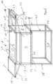
- the camping kitchen 1 has a cuboid storage space element 2 and a standing element 3 .
- the storage space element 3 comprises a front and a rear wall 4, 5, a top and a bottom wall 6, 7 and two side walls 8, 9.
- a flap 10 extending over the entire width of the front wall is formed in the front wall 4 .
- the flap 10 can be folded about a folding axis 12 parallel to an edge 11 formed between the front and bottom walls by means of hinges (not shown).
- a recess (not shown) is formed in the top wall 6, in which a two-flame gas hob 13, for example, is integrated.
- the hob 13 is integrated into the top wall 6 in such a way that a cover plate provided to cover the gas hobs ends approximately flush with the top wall 6 .
- a further recess 15 in which a water tap 16 can be arranged is provided laterally next to the hob 13 .
- the faucet 16 is releasably attached in the recess 15, for example by means of a click mechanism or by screwing.
- the faucet 16 also has a connector (not shown) for connecting to an internal water supply, such as a water canister, or an external water supply, such as a water tap.
- the water tap 16 can be arranged in the storage space element in the carrying position.
- the click mechanism can also be designed in such a way that the faucet is folded over in the direction of the upper wall and remains on it in the carrying position.
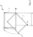
- the first frame-like folding element 18 is foldably connected to the storage space element 2 via two folding arms 20 ( figure 2 ).
- One end of the folding arms 20 is articulated in the area of the side wall 8 to the front and to the rear wall 4, 5.
- the folding element 18 is articulated to the other ends of the folding arms 20 in such a way that the folding element 18 is arranged essentially congruently in a carrying position on the top wall 6 of the storage space element 2 and optionally surrounds the water tap 16 . In a working position, the folding element 18 extends the upper wall 6 to the side.
- the second plate-shaped folding element 19 is also connected to the storage space element 2 so that it can be folded via two folding arms 21 .
- One end of the folding arms 21 is articulated in the area of the side wall 9 to the front and to the rear wall 4, 5.
- the folding element 19 is connected to the other ends of the folding arms 21 in an articulated manner in such a way that the folding element 19 is arranged essentially congruently on the top wall 6 of the storage space element 2 in a carrying position. In a working position, the folding element 19 extends the upper wall 6 to the side.
- a sink 22 can be arranged in the first plate-shaped folding element 18 ( figure 2 ).
- the sink 22 is preferably simply inserted into the frame-shaped first folding element 20 .
- corresponding fastening means for fixing the sink 22 in the folding element 18 can also be provided.
- the plate-shaped folding element 19 forms a worktop or an extension of the top wall 6 .
- the folding element 18 rests approximately flat on the top wall 6 such that an edge of the plate-shaped folding element 18 connected to the folding arms 20 rests approximately centrally in the area of the top wall 6 .
- a handle 23 pointing vertically upwards in the carrying position is provided on this edge.
- the folding element 18 is pivoted outwards in the lateral direction in such a way that the folding element 18 is folded about a further folding axis 14 by 180°.
- the folding axis 14 extends through the articulated connection of the folding arms 20 to the folding element 18 .
- the folding arms 20 rotate about an axis of rotation 17.
- the folding element 18 is supported in the vertical direction by the folding arms 20 and the top wall 6.
- Two spring-loaded fixing pins (not shown) are preferably provided for fixing the folding element 18 in the horizontal direction Area between the top wall 6 and the folding element 18 are arranged. In this way, a stable support surface is provided.
- the folding element 19 is pivoted outwards in the lateral direction in such a way that the folding element 19 is folded around a further folding axis 30 by 180°.
- the folding axis 30 extends through the articulated connection of the folding arms 21 to the folding element 19 .
- the folding arms 21 rotate about an axis of rotation 31.
- the folding element 19 is supported in the vertical direction by the folding arms 21 and the top wall 6.
- Two spring-loaded fixing pins (not shown) are preferably provided for fixing the folding element 19 in the horizontal direction Area between the top wall 6 and the folding element 19 are arranged.
- folding elements 18, 19 When the folding elements 18, 19 are folded in, a corresponding folding element 18, 19 is lifted upwards in the vertical direction in such a way that the folding element 18, 19 is folded about the folding axis 14, 30 by 180°.
- the folding arms 20, 21 rotate about the axis of rotation 17, 31.
- the folding elements 18, 19 are then approximately flush and parallel to the upper wall 6 on this.
- the folding elements 18, 19 are then fixed by means of the spring-loaded fixing pins (not shown).
- the fixing pins (not shown) are provided for fixing the folding arms in the carrying position.
- the fixing pins are arranged in corner regions of the top wall and are designed, for example, as cylindrical pins extending in the vertical direction.
- the folding elements 18, 19 have correspondingly arranged fixing elements.
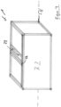
- the stand element 3 of the camping kitchen 1 is described below ( figure 1 ).
- the stand element has a rectangular support frame 24 and two foot frames 25,26.
- the foot frames 25, 26 extend on two opposite sides of the support frame 24 transversely to a surface 27 spanned by the support frame.
- the stand element 3 is pivotably connected to the storage space element 2 about a pivot axis 28, which extends parallel to an edge 29 formed between the rear and base walls 5, 7 of the storage space element 2, such that in a carrying position the foot frames 25, 26 are essentially congruent are arranged on the side walls of the storage space element and in a working position the foot frames 25, 26 extend the side walls 8, 9 in the vertical direction downwards ( figure 3 ).
- the frames 24, 25, 26 of the standing element 3 form a front frame wall 33, two side frame walls 34, 35, a rear frame wall 36, a top frame wall and a support frame wall 37 in a working position.
- a locking device is provided in order to fix the storage space element 2 and the standing element 3 in their position relative to one another.
- the locking device comprises a first and a second locking device 38, 39.
- the first locking device 38 fixes the standing element 3 and the storage space element 2 in the carrying position relative to one another.
- This first locking device 38 comprises two rotary bolts which are arranged approximately centrally on a strut of the support frame in such a way that they can be rotated about axes of rotation which are perpendicular to the front frame wall 33 of the stand element 3 .
- the turning bolts of the first locking device 38 fix the standing element 3 with respect to the storage space element 2 in such a way that the turning bolts rest on the top wall 6 of the storage space element 2 or on the folding elements 18, 19 and prevent the standing element 2 from swinging out.
- the second locking device 39 fixes the standing element 3 and the storage space element 2 in the working position relative to one another.
- This second locking device 39 comprises two rotating bolts, which are arranged on a respective strut of the foot frames 25, 26 in such a way that they can be rotated about axes of rotation that are perpendicular to the wall of the upper frame of the stand element 3.
- the rotary bolts of the second locking device 38 fix the standing element 3 with respect to the storage space element 2 in such a way that the bottom wall 7 of the storage space element 2 rests on the rotary bolts and prevent the standing element 2 from swiveling in.
- the locking device can also comprise a spring-loaded pin, which is arranged on the underside on the bottom wall 7 of the storage space element 3 and engages in corresponding recesses formed in the foot frames 25, 26 in order to fix the standing element 3 relative to the storage space element 2.
- feet 32 pointing downwards in the vertical direction are arranged.
- the feet 32 have threaded rods which engage with threads formed in the support frame 24 .
- the individual feet 32 can each be adjusted independently of one another in the vertical direction. This makes it possible to align the camping kitchen horizontally even on uneven surfaces.
- a further shelf (not shown) can be provided for accommodating objects.
- the sink is preferably designed to be collapsible, so that it requires as little space as possible when stowed away in the storage space element.
- the complete camping kitchen is placed on the bottom wall 7 of the storage space element 2 .
- the first locking device 38 in the region of the top wall 6 is then released by turning the rotating bolt by 90° and the storage space element 2 is lifted upwards in the vertical direction.
- the stand element 3 pivots about the pivot axis 28 formed in the area of the edge 29.
- the working position is rotated by means of the second locking device 39 the twist lock is fixed by 90°.
- the feet 32 are then adjusted so that the camping kitchen or the stand element 3 stands firmly on the ground.
- a pivoting of the standing element 3 to the storage space element 2 or a transfer of the camping kitchen from the working position to the carrying position is described below.
- the second locking device 39 in the area of the bottom wall 7 is released by turning the rotating bolt by 90° and the storage space element 2 is lowered in the vertical direction.
- the stand element 3 pivots about the pivot axis 28 formed in the area of the edge 29.
- the folding elements are actuated accordingly when setting up and folding, as explained above.
- the camping kitchen 1 and its storage space and stand element 2, 3 are preferably formed from interconnected profile bars made of metal, preferably aluminum, with a square cross-section.
- the method for transferring a camping kitchen from a carrying position to a working position and vice versa and the method for folding in and out a folding element of the camping kitchen can be summarized as follows.
Landscapes
- Engineering & Computer Science (AREA)
- Chemical & Material Sciences (AREA)
- Combustion & Propulsion (AREA)
- Mechanical Engineering (AREA)
- General Engineering & Computer Science (AREA)
- Food Science & Technology (AREA)
- Cookers (AREA)
Claims (14)
- Cuisine de camping portative, comprenantun élément de rangement (2) qui présente une paroi avant (4) et une paroi arrière (5), une paroi supérieure (6) et une paroi inférieure (7) ainsi que deux parois latérales (8, 9), un élément de support (3) qui présente un cadre d'appui rectangulaire (24) et deux cadres de pied (25, 26), les cadres de pied (25, 26) s'étendant sur deux côtés opposés du cadre d'appui (24), transversalement à une surface tendue par le cadre d'appui (24), et l'élément de support (3) étant relié à l'élément de rangement (2) de manière à pouvoir pivoter autour d'un axe de rotation (28) qui s'étend parallèlement à un bord formée entre la paroi arrière et la paroi de fond (7) de l'élément de rangement (2), de telle sorte quedans une position de support, les cadres de pied (25, 26) sont disposés essentiellement en coïncidence sur les parois latérales (8, 9) de l'élément de rangement (2), et dans une position de travail, les cadres de pied (25, 26) prolongent les parois latérales (8, 9) vers le bas dans le sens vertical,un dispositif d'arrêt (38, 39) étant prévu pour fixer l'élément de rangement (2) et l'élément de support (3) dans leur position l'un par rapport à l'autre.
- Cuisine de camping selon la revendication 1,
caractérisée en ce que
l'élément de rangement (2) est réalisé en forme de parallélépipède. - Cuisine de camping selon la revendication 1 ou 2,
caractérisée en ce qu'un premier élément rabattable (18) réalisé en forme de cadre est prévu, qui est relié de manière rabattable à l'élément de rangement (2) par l'intermédiaire de deux bras rabattables (20, 21), une extrémité de chacun des bras rabattables (20, 21) étant reliée dans la zone de la paroi latérale (8, 9) de manière articulée à la paroi avant (4) et à la paroi arrière (5) et l'élément rabattable (18) est relié de manière articulée aux autres extrémités des bras pivotants de telle sorte que l'élément rabattable (18), dans une position de support, est disposé essentiellement en coïncidence sur la paroi supérieure (6) de l'élément de rangement (2) et l'élément rabattable (18), dans une position de travail, prolonge la paroi supérieure (6) vers le côté
et/ouun deuxième élément rabattable (19) en forme de plaque est prévu, qui est relié de manière rabattable à l'élément de rangement (2) par l'intermédiaire de deux bras rabattables (20, 21), une extrémité de chacun des bras rabattables (20, 21) étant reliée de manière articulée à la paroi avant (4) et à la paroi arrière (5) dans la zone de la paroi latérale (8, 9) et l'élément rabattable (19) est relié de manière articulée aux autres extrémités des bras pivotants de telle sorte que l'élément rabattable (19) est disposé dans une position de support essentiellement en coïncidence sur la paroi supérieure (6) de l'élément de rangement (2), et l'élément rabattable (19), dans une position de travail, prolonge la paroi supérieure (6) vers le côté. - Cuisine de camping selon l'une quelconque des revendications 1 à 3,
caractérisée en ce queun évier (22) peut être fixé de manière amovible dans l'élément rabattable (19) réalisé en forme de cadre dans la position de travail, l'évier (22) pouvant être disposé dans une position de support dans l'élément de rangement (2)
et/ouun élément de cuisson (13) étant prévu dans l'élément de rangement (2), qui est disposé essentiellement à fleur de la paroi supérieure (6) de l'élément de rangement (2)
et/oudans la position de travail, un robinet d'eau (16) peut être fixé de manière amovible sur la paroi supérieure (6) de l'élément de rangement (2) adjacent à l'évier (22), le robinet d'eau (16) pouvant être disposé dans une position de support dans l'élément de rangement (2) ou sur la paroi supérieure (6)
et/oul'évier (22) est réalisé de manière à pouvoir être replié. - Cuisine de camping selon l'une quelconque des revendications 1 à 4,
caractérisée en ce queles cadres sont réalisés en profilés d'aluminium, d'acier, d'acier inoxydable, de bois, de carbone ou de matière plastique
et/ouque les parois sont réalisées en plaques d'aluminium, d'acier, d'acier inoxydable, de bois, de carbone ou de matière plastique. - Cuisine de camping selon l'une quelconque des revendications 1 à 5,
caractérisée en ce que
le dispositif d'arrêt (38, 39) comprend de préférence un premier (38) et un deuxième (39) dispositifs d'arrêt. - Cuisine de camping selon la revendication 6,
caractérisée en ce que
le premier dispositif d'arrêt (38) fixe l'élément de support (3) et l'élément de rangement (2) l'un par rapport à l'autre dans la position de support, ce premier dispositif d'arrêt (38) comprenant deux verrous rotatifs qui sont disposés à peu près au milieu sur une entretoise du cadre d'appui (24) de telle sorte qu'ils peuvent pivoter autour d'axes de rotation (31) perpendiculaires à une paroi de cadre avant de l'élément de support (3) et les verrous rotatifs du premier dispositif d'arrêt (38) fixent l'élément de support (3) par rapport à l'élément de rangement (2) dans la position de support de telle sorte que les verrous rotatifs reposent sur la paroi supérieure (6) de l'élément de rangement (2) ou sur les éléments rabattables (19) et empêchent un pivotement de l'élément de support (3). - Cuisine de camping selon la revendication 6 ou 7,
caractérisée en ce que
le deuxième dispositif d'arrêt (39) fixe l'élément de support (3) et l'élément de rangement (2) l'un par rapport à l'autre dans la position de travail, ce deuxième dispositif d'arrêt (39) comprenant deux verrous rotatifs qui sont disposés sur une entretoise respective des cadres de pied (25, 26) de telle sorte qu'ils peuvent pivoter autour d'axes de rotation (31) perpendiculaires à une paroi de cadre supérieur de l'élément de support (3) et les verrous rotatifs du deuxième dispositif d'arrêt (39) fixent l'élément de support (3) par rapport à l'élément de rangement (2) dans la position de travail de telle sorte que la paroi de fond (7) de l'élément de rangement (2) repose sur les verrous rotatifs et empêche un pivotement de l'élément de support (3). - Procédé de transfert d'une cuisine de camping selon l'une quelconque des revendications 1 à 8, d'une position de support à une position de travail et donc pour faire pivoter un élément de support (3) d'un élément de rangement (2), comprenant les étapes suivantes :Disposition de la cuisine de camping sur un cadre d'appui (24) ou sur la paroi du cadre de fond de l'élément de support (3),desserrage d'un premier dispositif d'arrêt (38) entre l'élément de support (3) et l'élément de rangement (2),Soulèvement de l'élément de rangement (2) dans le sens vertical vers le haut de telle sorte que l'élément de support (3) pivote autour d'un axe de rotation (28) dans le sens vertical vers le bas,Appui sur une surface d'appui de l'élément de rangement (2) sur un support, alignement horizontalement de la paroi supérieure (6), etFixation de la position de travail au moyen d'un deuxième dispositif d'arrêt (39).
- Procédé selon la revendication 9,
caractérisé en ce qu'
un réglage des pieds de support est effectué de telle sorte que l'élément de support (3) repose de manière stable sur un support. - Procédé selon la revendication 9, comprenant les étapes suivantes :Pivotement de l'élément rabattable (19) en direction latérale vers l'extérieur de telle sorte qu'un rabattement de l'élément rabattable (19) s'effectue autour d'un autre axe de rabattement de 180°, l'axe de rabattement s'étendant à travers une liaison articulée des bras rabattables (20, 21) avec l'élément rabattable (19),Appui sur un bord de l'élément rabattable (19) opposé au bord relié aux bras rabattables (20, 21) dans la zone d'une paroi latérale correspondante (8, 9) de la paroi supérieure (6), les bras rabattables (20, 21) pivotant alors autour d'un axe de rotation (31),Support de l'élément rabattable (19) dans le sens vertical par les bras rabattables (20, 21) et la paroi supérieure (6)
et/ouFixation l'élément rabattable (19) dans la direction horizontale au moyen d'un dispositif de fixation correspondant. - Procédé de transfert d'une cuisine de camping selon l'une quelconque des revendications 1 à 8 d'une position de travail à une position de support et pour faire ainsi pivoter un élément de support (3) vers l'élément de rangement (2), comprenant les étapes suivantes :Disposition de la cuisine de camping sur un cadre d'appui (24) ou sur la paroi du cadre de fond de l'élément de support (3),Desserrage d'un deuxième dispositif d' arrêt (39) entre l'élément de support (3) et l'élément de rangement (2),Abaissement de l'élément de rangement (2) dans le sens vertical vers le bas de telle sorte que l'élément de support (3) pivote autour d'un axe de rotation (28) dans le sens vertical vers le haut,Appui sur une paroi de fond (7) de l'élément de rangement (2) et d'un cadre d'appui (24) ou de la paroi du cadre de fond de l'élément de support (3) sur un support, de sorte que le cadre d'appui (24) de l'élément de support (3) est disposé parallèlement à une paroi avant de l'élément de rangement (2),Fixation de la position de support au moyen d'un premier dispositif de d'arrêt (38).
- Procédé selon la revendication 12, comprenant les étapes suivantes :Soulèvement d'un élément de rabattable (19) dans le sens vertical vers le haut de telle sorte qu'il se produise un rabattement de l'élément de rabattage (19) autour d'un axe de rabattement de 180°, et pivotement des bras rabattables (20, 21) autour de l'axe de rotation (31), appui à peu près à fleur des éléments rabattables (19) sur une paroi supérieure (6)
et/ouFixation de l'élément rabattable (19) moyen d'un dispositif de fixation correspondant. - Procédé selon l'une quelconque des revendications 9 à 13,
caractérisé en ce que
le procédé est mis en oeuvre avec un dispositif selon l'une quelconque des revendications 1 à 8.
Applications Claiming Priority (3)
| Application Number | Priority Date | Filing Date | Title |
|---|---|---|---|
| DE202016107218.2U DE202016107218U1 (de) | 2016-12-21 | 2016-12-21 | Tragbare Campingküche |
| ATA50518/2017A AT519485B1 (de) | 2016-12-21 | 2017-06-22 | Tragbare Campingküche |
| PCT/EP2017/083138 WO2018114712A1 (fr) | 2016-12-21 | 2017-12-15 | Cuisine de camping portative et procédé de montage et de démontage de ladite cuisine de camping |
Publications (2)
| Publication Number | Publication Date |
|---|---|
| EP3558057A1 EP3558057A1 (fr) | 2019-10-30 |
| EP3558057B1 true EP3558057B1 (fr) | 2023-04-12 |
Family
ID=61912687
Family Applications (1)
| Application Number | Title | Priority Date | Filing Date |
|---|---|---|---|
| EP17821872.3A Active EP3558057B1 (fr) | 2016-12-21 | 2017-12-15 | Cuisine de camping portative et procédé de montage et de démontage de ladite cuisine de camping |
Country Status (3)
| Country | Link |
|---|---|
| EP (1) | EP3558057B1 (fr) |
| AT (1) | AT519485B1 (fr) |
| DE (1) | DE202016107218U1 (fr) |
Families Citing this family (2)
| Publication number | Priority date | Publication date | Assignee | Title |
|---|---|---|---|---|
| CN108772815A (zh) * | 2018-06-22 | 2018-11-09 | 江西昌河汽车有限责任公司 | 一种置物方便的置物架 |
| US11466861B2 (en) * | 2019-02-20 | 2022-10-11 | Nomad Kitchen Company LLC | Mobile kitchen unit |
Citations (1)
| Publication number | Priority date | Publication date | Assignee | Title |
|---|---|---|---|---|
| US7032910B2 (en) * | 2002-05-13 | 2006-04-25 | Baxter International Inc. | Adaptable blood processing platforms |
Family Cites Families (7)
| Publication number | Priority date | Publication date | Assignee | Title |
|---|---|---|---|---|
| DE1793074U (de) * | 1959-04-02 | 1959-08-06 | Kurt Vogt | In einen campingtisch bzw. transportkiste verwandelbare kochkiste. |
| GB1030293A (en) | 1964-04-10 | 1966-05-18 | Seadam Equipment Ltd | Improvements in or relating to camp kitchens |
| US3915529A (en) * | 1971-05-18 | 1975-10-28 | Edgar R Bernier | Compact field kitchen |
| IT235741Y1 (it) * | 1995-12-18 | 2000-07-12 | Tomat Dany Severino | Cucina portatile |
| US6543436B2 (en) * | 2000-11-06 | 2003-04-08 | Dennis Montgomery | Portable chuckwagon camp box |
| DE102006032227A1 (de) * | 2006-07-07 | 2008-01-10 | Rieber Gmbh & Co. Kg | Mobile Vorrichtung für eine Heizeinrichtung und Kochvorrichtung |
| DE202013007494U1 (de) | 2013-08-21 | 2013-09-13 | Ralf Scherer | Tragbarer Arbeits-und Freizeitkoffer mit abklappbarer Arbeitsplatte, Schubladen-und Regalsystem |
-
2016
- 2016-12-21 DE DE202016107218.2U patent/DE202016107218U1/de not_active Expired - Lifetime
-
2017
- 2017-06-22 AT ATA50518/2017A patent/AT519485B1/de not_active IP Right Cessation
- 2017-12-15 EP EP17821872.3A patent/EP3558057B1/fr active Active
Patent Citations (1)
| Publication number | Priority date | Publication date | Assignee | Title |
|---|---|---|---|---|
| US7032910B2 (en) * | 2002-05-13 | 2006-04-25 | Baxter International Inc. | Adaptable blood processing platforms |
Also Published As
| Publication number | Publication date |
|---|---|
| AT519485A1 (de) | 2018-07-15 |
| DE202016107218U1 (de) | 2018-03-22 |
| AT519485B1 (de) | 2019-01-15 |
| EP3558057A1 (fr) | 2019-10-30 |
Similar Documents
| Publication | Publication Date | Title |
|---|---|---|
| EP0166910B1 (fr) | Combinaison de table et banc pliants | |
| EP3558057B1 (fr) | Cuisine de camping portative et procédé de montage et de démontage de ladite cuisine de camping | |
| DE60218801T2 (de) | Zusammenklappbarer Wagen mit Fachboden | |
| DE60017122T2 (de) | Zusammenklappbarer karren mit regalboden | |
| DE102020206185B4 (de) | Beistellwagen sowie Küchensystem mit einem Beistellwagen | |
| DE202018100440U1 (de) | Mobile Theke für den Gaststättenbetrieb | |
| EP3802272A1 (fr) | Véhicule de transport et dispositif de transport | |
| DE102021214602B4 (de) | Küchensystem | |
| DE19837987A1 (de) | Tisch mit einer Tischplatte | |
| WO2018114712A1 (fr) | Cuisine de camping portative et procédé de montage et de démontage de ladite cuisine de camping | |
| DE102018218825B4 (de) | Tisch mit einer Tischplatte und einem die Tischplatte tragenden Faltgestell | |
| DE10144353A1 (de) | Innenstellage für ein Motorfahrzeug | |
| DE10038223B4 (de) | Klapptisch | |
| DE10034159A1 (de) | Transportgerät für Gepäckstücke | |
| DE10157602A1 (de) | Transportwagen | |
| DE202004020135U1 (de) | Handgeführter Wagen | |
| DE8613639U1 (de) | Schrankaufbau | |
| DE102009035887B4 (de) | Vorrichtung zur Beleuchtung einer Bar oder Theke | |
| EP2508306B1 (fr) | Coffre à outils déployable | |
| DE1945301U (de) | Mehrzweck-moebelstueck. | |
| DE102006057394A1 (de) | Mobiler Klapptresen | |
| DE19960169A1 (de) | Tisch für ein Fahrzeug | |
| DE10043537B4 (de) | Mobile Werkbank | |
| EP3088246A1 (fr) | Boite de camping | |
| DE60011442T2 (de) | Umwandelbare heizkörperabdeckung |
Legal Events
| Date | Code | Title | Description |
|---|---|---|---|
| STAA | Information on the status of an ep patent application or granted ep patent |
Free format text: STATUS: UNKNOWN |
|
| STAA | Information on the status of an ep patent application or granted ep patent |
Free format text: STATUS: THE INTERNATIONAL PUBLICATION HAS BEEN MADE |
|
| PUAI | Public reference made under article 153(3) epc to a published international application that has entered the european phase |
Free format text: ORIGINAL CODE: 0009012 |
|
| STAA | Information on the status of an ep patent application or granted ep patent |
Free format text: STATUS: REQUEST FOR EXAMINATION WAS MADE |
|
| 17P | Request for examination filed |
Effective date: 20190717 |
|
| AK | Designated contracting states |
Kind code of ref document: A1 Designated state(s): AL AT BE BG CH CY CZ DE DK EE ES FI FR GB GR HR HU IE IS IT LI LT LU LV MC MK MT NL NO PL PT RO RS SE SI SK SM TR |
|
| AX | Request for extension of the european patent |
Extension state: BA ME |
|
| DAV | Request for validation of the european patent (deleted) | ||
| DAX | Request for extension of the european patent (deleted) | ||
| GRAP | Despatch of communication of intention to grant a patent |
Free format text: ORIGINAL CODE: EPIDOSNIGR1 |
|
| STAA | Information on the status of an ep patent application or granted ep patent |
Free format text: STATUS: GRANT OF PATENT IS INTENDED |
|
| INTG | Intention to grant announced |
Effective date: 20221019 |
|
| GRAS | Grant fee paid |
Free format text: ORIGINAL CODE: EPIDOSNIGR3 |
|
| GRAA | (expected) grant |
Free format text: ORIGINAL CODE: 0009210 |
|
| STAA | Information on the status of an ep patent application or granted ep patent |
Free format text: STATUS: THE PATENT HAS BEEN GRANTED |
|
| AK | Designated contracting states |
Kind code of ref document: B1 Designated state(s): AL AT BE BG CH CY CZ DE DK EE ES FI FR GB GR HR HU IE IS IT LI LT LU LV MC MK MT NL NO PL PT RO RS SE SI SK SM TR |
|
| REG | Reference to a national code |
Ref country code: GB Ref legal event code: FG4D Free format text: NOT ENGLISH |
|
| REG | Reference to a national code |
Ref country code: CH Ref legal event code: EP |
|
| REG | Reference to a national code |
Ref country code: DE Ref legal event code: R096 Ref document number: 502017014620 Country of ref document: DE |
|
| REG | Reference to a national code |
Ref country code: IE Ref legal event code: FG4D Free format text: LANGUAGE OF EP DOCUMENT: GERMAN |
|
| REG | Reference to a national code |
Ref country code: AT Ref legal event code: REF Ref document number: 1559328 Country of ref document: AT Kind code of ref document: T Effective date: 20230515 |
|
| REG | Reference to a national code |
Ref country code: LT Ref legal event code: MG9D |
|
| REG | Reference to a national code |
Ref country code: NL Ref legal event code: MP Effective date: 20230412 |
|
| PG25 | Lapsed in a contracting state [announced via postgrant information from national office to epo] |
Ref country code: NL Free format text: LAPSE BECAUSE OF FAILURE TO SUBMIT A TRANSLATION OF THE DESCRIPTION OR TO PAY THE FEE WITHIN THE PRESCRIBED TIME-LIMIT Effective date: 20230412 |
|
| PG25 | Lapsed in a contracting state [announced via postgrant information from national office to epo] |
Ref country code: SE Free format text: LAPSE BECAUSE OF FAILURE TO SUBMIT A TRANSLATION OF THE DESCRIPTION OR TO PAY THE FEE WITHIN THE PRESCRIBED TIME-LIMIT Effective date: 20230412 Ref country code: PT Free format text: LAPSE BECAUSE OF FAILURE TO SUBMIT A TRANSLATION OF THE DESCRIPTION OR TO PAY THE FEE WITHIN THE PRESCRIBED TIME-LIMIT Effective date: 20230814 Ref country code: NO Free format text: LAPSE BECAUSE OF FAILURE TO SUBMIT A TRANSLATION OF THE DESCRIPTION OR TO PAY THE FEE WITHIN THE PRESCRIBED TIME-LIMIT Effective date: 20230712 Ref country code: ES Free format text: LAPSE BECAUSE OF FAILURE TO SUBMIT A TRANSLATION OF THE DESCRIPTION OR TO PAY THE FEE WITHIN THE PRESCRIBED TIME-LIMIT Effective date: 20230412 |
|
| PG25 | Lapsed in a contracting state [announced via postgrant information from national office to epo] |
Ref country code: RS Free format text: LAPSE BECAUSE OF FAILURE TO SUBMIT A TRANSLATION OF THE DESCRIPTION OR TO PAY THE FEE WITHIN THE PRESCRIBED TIME-LIMIT Effective date: 20230412 Ref country code: PL Free format text: LAPSE BECAUSE OF FAILURE TO SUBMIT A TRANSLATION OF THE DESCRIPTION OR TO PAY THE FEE WITHIN THE PRESCRIBED TIME-LIMIT Effective date: 20230412 Ref country code: LV Free format text: LAPSE BECAUSE OF FAILURE TO SUBMIT A TRANSLATION OF THE DESCRIPTION OR TO PAY THE FEE WITHIN THE PRESCRIBED TIME-LIMIT Effective date: 20230412 Ref country code: LT Free format text: LAPSE BECAUSE OF FAILURE TO SUBMIT A TRANSLATION OF THE DESCRIPTION OR TO PAY THE FEE WITHIN THE PRESCRIBED TIME-LIMIT Effective date: 20230412 Ref country code: IS Free format text: LAPSE BECAUSE OF FAILURE TO SUBMIT A TRANSLATION OF THE DESCRIPTION OR TO PAY THE FEE WITHIN THE PRESCRIBED TIME-LIMIT Effective date: 20230812 Ref country code: HR Free format text: LAPSE BECAUSE OF FAILURE TO SUBMIT A TRANSLATION OF THE DESCRIPTION OR TO PAY THE FEE WITHIN THE PRESCRIBED TIME-LIMIT Effective date: 20230412 Ref country code: GR Free format text: LAPSE BECAUSE OF FAILURE TO SUBMIT A TRANSLATION OF THE DESCRIPTION OR TO PAY THE FEE WITHIN THE PRESCRIBED TIME-LIMIT Effective date: 20230713 Ref country code: AL Free format text: LAPSE BECAUSE OF FAILURE TO SUBMIT A TRANSLATION OF THE DESCRIPTION OR TO PAY THE FEE WITHIN THE PRESCRIBED TIME-LIMIT Effective date: 20230412 |
|
| PG25 | Lapsed in a contracting state [announced via postgrant information from national office to epo] |
Ref country code: FI Free format text: LAPSE BECAUSE OF FAILURE TO SUBMIT A TRANSLATION OF THE DESCRIPTION OR TO PAY THE FEE WITHIN THE PRESCRIBED TIME-LIMIT Effective date: 20230412 |
|
| REG | Reference to a national code |
Ref country code: DE Ref legal event code: R097 Ref document number: 502017014620 Country of ref document: DE |
|
| PG25 | Lapsed in a contracting state [announced via postgrant information from national office to epo] |
Ref country code: SK Free format text: LAPSE BECAUSE OF FAILURE TO SUBMIT A TRANSLATION OF THE DESCRIPTION OR TO PAY THE FEE WITHIN THE PRESCRIBED TIME-LIMIT Effective date: 20230412 |
|
| PG25 | Lapsed in a contracting state [announced via postgrant information from national office to epo] |
Ref country code: SM Free format text: LAPSE BECAUSE OF FAILURE TO SUBMIT A TRANSLATION OF THE DESCRIPTION OR TO PAY THE FEE WITHIN THE PRESCRIBED TIME-LIMIT Effective date: 20230412 Ref country code: SK Free format text: LAPSE BECAUSE OF FAILURE TO SUBMIT A TRANSLATION OF THE DESCRIPTION OR TO PAY THE FEE WITHIN THE PRESCRIBED TIME-LIMIT Effective date: 20230412 Ref country code: RO Free format text: LAPSE BECAUSE OF FAILURE TO SUBMIT A TRANSLATION OF THE DESCRIPTION OR TO PAY THE FEE WITHIN THE PRESCRIBED TIME-LIMIT Effective date: 20230412 Ref country code: EE Free format text: LAPSE BECAUSE OF FAILURE TO SUBMIT A TRANSLATION OF THE DESCRIPTION OR TO PAY THE FEE WITHIN THE PRESCRIBED TIME-LIMIT Effective date: 20230412 Ref country code: DK Free format text: LAPSE BECAUSE OF FAILURE TO SUBMIT A TRANSLATION OF THE DESCRIPTION OR TO PAY THE FEE WITHIN THE PRESCRIBED TIME-LIMIT Effective date: 20230412 Ref country code: CZ Free format text: LAPSE BECAUSE OF FAILURE TO SUBMIT A TRANSLATION OF THE DESCRIPTION OR TO PAY THE FEE WITHIN THE PRESCRIBED TIME-LIMIT Effective date: 20230412 |
|
| PGFP | Annual fee paid to national office [announced via postgrant information from national office to epo] |
Ref country code: DE Payment date: 20231208 Year of fee payment: 7 Ref country code: AT Payment date: 20231204 Year of fee payment: 7 |
|
| PLBE | No opposition filed within time limit |
Free format text: ORIGINAL CODE: 0009261 |
|
| STAA | Information on the status of an ep patent application or granted ep patent |
Free format text: STATUS: NO OPPOSITION FILED WITHIN TIME LIMIT |
|
| 26N | No opposition filed |
Effective date: 20240115 |
|
| PGFP | Annual fee paid to national office [announced via postgrant information from national office to epo] |
Ref country code: CH Payment date: 20240117 Year of fee payment: 7 |
|
| PG25 | Lapsed in a contracting state [announced via postgrant information from national office to epo] |
Ref country code: SI Free format text: LAPSE BECAUSE OF FAILURE TO SUBMIT A TRANSLATION OF THE DESCRIPTION OR TO PAY THE FEE WITHIN THE PRESCRIBED TIME-LIMIT Effective date: 20230412 |
|
| PG25 | Lapsed in a contracting state [announced via postgrant information from national office to epo] |
Ref country code: SI Free format text: LAPSE BECAUSE OF FAILURE TO SUBMIT A TRANSLATION OF THE DESCRIPTION OR TO PAY THE FEE WITHIN THE PRESCRIBED TIME-LIMIT Effective date: 20230412 Ref country code: IT Free format text: LAPSE BECAUSE OF FAILURE TO SUBMIT A TRANSLATION OF THE DESCRIPTION OR TO PAY THE FEE WITHIN THE PRESCRIBED TIME-LIMIT Effective date: 20230412 |
|
| PG25 | Lapsed in a contracting state [announced via postgrant information from national office to epo] |
Ref country code: LU Free format text: LAPSE BECAUSE OF NON-PAYMENT OF DUE FEES Effective date: 20231215 |
|
| PG25 | Lapsed in a contracting state [announced via postgrant information from national office to epo] |
Ref country code: MC Free format text: LAPSE BECAUSE OF FAILURE TO SUBMIT A TRANSLATION OF THE DESCRIPTION OR TO PAY THE FEE WITHIN THE PRESCRIBED TIME-LIMIT Effective date: 20230412 |
|
| GBPC | Gb: european patent ceased through non-payment of renewal fee |
Effective date: 20231215 |
|
| REG | Reference to a national code |
Ref country code: BE Ref legal event code: MM Effective date: 20231231 |
|
| PG25 | Lapsed in a contracting state [announced via postgrant information from national office to epo] |
Ref country code: MC Free format text: LAPSE BECAUSE OF FAILURE TO SUBMIT A TRANSLATION OF THE DESCRIPTION OR TO PAY THE FEE WITHIN THE PRESCRIBED TIME-LIMIT Effective date: 20230412 Ref country code: LU Free format text: LAPSE BECAUSE OF NON-PAYMENT OF DUE FEES Effective date: 20231215 |