EP3557715A1 - Stromversorgungssystem - Google Patents
Stromversorgungssystem Download PDFInfo
- Publication number
- EP3557715A1 EP3557715A1 EP19164848.4A EP19164848A EP3557715A1 EP 3557715 A1 EP3557715 A1 EP 3557715A1 EP 19164848 A EP19164848 A EP 19164848A EP 3557715 A1 EP3557715 A1 EP 3557715A1
- Authority
- EP
- European Patent Office
- Prior art keywords
- power
- electric power
- storage battery
- building
- person
- Prior art date
- Legal status (The legal status is an assumption and is not a legal conclusion. Google has not performed a legal analysis and makes no representation as to the accuracy of the status listed.)
- Granted
Links
Images



Classifications
-
- H—ELECTRICITY
- H02—GENERATION; CONVERSION OR DISTRIBUTION OF ELECTRIC POWER
- H02J—ELECTRIC POWER NETWORKS; CIRCUIT ARRANGEMENTS OR SYSTEMS FOR SUPPLYING OR DISTRIBUTING ELECTRIC POWER; SYSTEMS FOR STORING ELECTRIC ENERGY
- H02J3/00—Circuit arrangements for AC mains or AC distribution networks
- H02J3/28—Arrangements for balancing of the load in networks by storage of energy
- H02J3/32—Arrangements for balancing of the load in networks by storage of energy using batteries or super capacitors with converting means
-
- G—PHYSICS
- G05—CONTROLLING; REGULATING
- G05F—SYSTEMS FOR REGULATING ELECTRIC OR MAGNETIC VARIABLES
- G05F1/00—Automatic systems in which deviations of an electric quantity from one or more predetermined values are detected at the output of the system and fed back to a device within the system to restore the detected quantity to its predetermined value or values, i.e. retroactive systems
- G05F1/66—Regulating electric power
-
- H—ELECTRICITY
- H01—ELECTRIC ELEMENTS
- H01M—PROCESSES OR MEANS, e.g. BATTERIES, FOR THE DIRECT CONVERSION OF CHEMICAL ENERGY INTO ELECTRICAL ENERGY
- H01M8/00—Fuel cells; Manufacture thereof
- H01M8/22—Fuel cells in which the fuel is based on materials comprising carbon or oxygen or hydrogen and other elements; Fuel cells in which the fuel is based on materials comprising only elements other than carbon, oxygen or hydrogen
-
- H—ELECTRICITY
- H02—GENERATION; CONVERSION OR DISTRIBUTION OF ELECTRIC POWER
- H02J—ELECTRIC POWER NETWORKS; CIRCUIT ARRANGEMENTS OR SYSTEMS FOR SUPPLYING OR DISTRIBUTING ELECTRIC POWER; SYSTEMS FOR STORING ELECTRIC ENERGY
- H02J3/00—Circuit arrangements for AC mains or AC distribution networks
- H02J3/38—Arrangements for feeding a single network from two or more generators or sources in parallel; Arrangements for feeding already energised networks from additional generators or sources in parallel
-
- H—ELECTRICITY
- H02—GENERATION; CONVERSION OR DISTRIBUTION OF ELECTRIC POWER
- H02J—ELECTRIC POWER NETWORKS; CIRCUIT ARRANGEMENTS OR SYSTEMS FOR SUPPLYING OR DISTRIBUTING ELECTRIC POWER; SYSTEMS FOR STORING ELECTRIC ENERGY
- H02J3/00—Circuit arrangements for AC mains or AC distribution networks
- H02J3/38—Arrangements for feeding a single network from two or more generators or sources in parallel; Arrangements for feeding already energised networks from additional generators or sources in parallel
- H02J3/381—Dispersed generators
-
- H—ELECTRICITY
- H01—ELECTRIC ELEMENTS
- H01M—PROCESSES OR MEANS, e.g. BATTERIES, FOR THE DIRECT CONVERSION OF CHEMICAL ENERGY INTO ELECTRICAL ENERGY
- H01M8/00—Fuel cells; Manufacture thereof
- H01M8/04—Auxiliary arrangements, e.g. for control of pressure or for circulation of fluids
- H01M8/04298—Processes for controlling fuel cells or fuel cell systems
- H01M8/04313—Processes for controlling fuel cells or fuel cell systems characterised by the detection or assessment of variables; characterised by the detection or assessment of failure or abnormal function
-
- H—ELECTRICITY
- H02—GENERATION; CONVERSION OR DISTRIBUTION OF ELECTRIC POWER
- H02J—ELECTRIC POWER NETWORKS; CIRCUIT ARRANGEMENTS OR SYSTEMS FOR SUPPLYING OR DISTRIBUTING ELECTRIC POWER; SYSTEMS FOR STORING ELECTRIC ENERGY
- H02J2101/00—Supply or distribution of decentralised, dispersed or local electric power generation
- H02J2101/20—Dispersed power generation using renewable energy sources
- H02J2101/30—Fuel cells
-
- Y—GENERAL TAGGING OF NEW TECHNOLOGICAL DEVELOPMENTS; GENERAL TAGGING OF CROSS-SECTIONAL TECHNOLOGIES SPANNING OVER SEVERAL SECTIONS OF THE IPC; TECHNICAL SUBJECTS COVERED BY FORMER USPC CROSS-REFERENCE ART COLLECTIONS [XRACs] AND DIGESTS
- Y02—TECHNOLOGIES OR APPLICATIONS FOR MITIGATION OR ADAPTATION AGAINST CLIMATE CHANGE
- Y02E—REDUCTION OF GREENHOUSE GAS [GHG] EMISSIONS, RELATED TO ENERGY GENERATION, TRANSMISSION OR DISTRIBUTION
- Y02E60/00—Enabling technologies; Technologies with a potential or indirect contribution to GHG emissions mitigation
- Y02E60/30—Hydrogen technology
- Y02E60/36—Hydrogen production from non-carbon containing sources, e.g. by water electrolysis
-
- Y—GENERAL TAGGING OF NEW TECHNOLOGICAL DEVELOPMENTS; GENERAL TAGGING OF CROSS-SECTIONAL TECHNOLOGIES SPANNING OVER SEVERAL SECTIONS OF THE IPC; TECHNICAL SUBJECTS COVERED BY FORMER USPC CROSS-REFERENCE ART COLLECTIONS [XRACs] AND DIGESTS
- Y02—TECHNOLOGIES OR APPLICATIONS FOR MITIGATION OR ADAPTATION AGAINST CLIMATE CHANGE
- Y02E—REDUCTION OF GREENHOUSE GAS [GHG] EMISSIONS, RELATED TO ENERGY GENERATION, TRANSMISSION OR DISTRIBUTION
- Y02E60/00—Enabling technologies; Technologies with a potential or indirect contribution to GHG emissions mitigation
- Y02E60/30—Hydrogen technology
- Y02E60/50—Fuel cells
-
- Y—GENERAL TAGGING OF NEW TECHNOLOGICAL DEVELOPMENTS; GENERAL TAGGING OF CROSS-SECTIONAL TECHNOLOGIES SPANNING OVER SEVERAL SECTIONS OF THE IPC; TECHNICAL SUBJECTS COVERED BY FORMER USPC CROSS-REFERENCE ART COLLECTIONS [XRACs] AND DIGESTS
- Y02—TECHNOLOGIES OR APPLICATIONS FOR MITIGATION OR ADAPTATION AGAINST CLIMATE CHANGE
- Y02E—REDUCTION OF GREENHOUSE GAS [GHG] EMISSIONS, RELATED TO ENERGY GENERATION, TRANSMISSION OR DISTRIBUTION
- Y02E70/00—Other energy conversion or management systems reducing GHG emissions
- Y02E70/30—Systems combining energy storage with energy generation of non-fossil origin
Definitions
- the present disclosure relates to a power system.
- Japanese Patent No. 5547902 discloses a human detection unit provided in the photovoltaic power generation device and the storage battery where the electric utility rate information of electric power supplied from the grid is acquired, control for charging and discharging the storage battery economically from the average value of the electric utility rate of the amount of electricity stored in the storage battery is performed, and electric power is suppled to facilities in the building by performing setting from a plurality of modes based on human detection information.
- Japanese Patent No. 6189448 discloses a control unit that stores surplus electric power, which is not supplied from the photovoltaic power generation device to the facility, in the storage battery and the hydrogen production device in a form of electricity and hydrogen during the day, and controls electric power from the fuel cell and the storage battery at night, where based on the predicted value of the power generation amount and the predicted value of the electric power demand amount, the electric power to be supplied to the storage battery and the hydrogen production device during the day is to determined, and the electric power to be supplied from the storage battery and the fuel cell to the facility at night is determined.
- the conventional example has not taken it into consideration to appropriately store the electric power obtained from renewable energy in a device suitable for short-term energy storage and a device suitable for long-term energy storage.
- no consideration has been given to an appropriate supply of electric power to a power load provided in a building from a device suitable for short term energy output and a device suitable for long-term energy output.
- One non-limiting and exemplary embodiment provides a power system capable of appropriately storing electric power obtained from renewable energy in a device suitable for short-term energy storage and a device suitable for long-term energy storage.
- One non-limiting and exemplary embodiment provides a power system capable of appropriately supplying electric power to a power load provided in a building from a device suitable for short term energy output and a device suitable for long-term energy output.
- the techniques disclosed here feature a power system that includes: a storage battery; a water electrolyzer; a fuel cell that generates electricity using hydrogen supplied from a hydrogen reservoir that stores hydrogen generated by the water electrolyzer; a detector that detects whether there is a person in a building; and a controller that performs at least one of first control and second control.
- the first control determines a priority between the storage battery and the water electrolyzer, to which electric power is supplied from a power generation device using renewable energy, based on information detected by the detector.
- the second control determines a priority between the storage battery and the fuel cell, from which electric power is supplied to a power load provided in the building, based on the information detected by the detector.
- the power system of one aspect of the present disclosure has an effect of capable of appropriately storing the electric power obtained from renewable energy in a device suitable for short-term energy storage and a device suitable for long-term energy storage.
- the power system of one aspect of the present disclosure has an effect of capable of appropriately supplying electric power to a power load provided in a building from a device suitable for short term energy output and a device suitable for long-term energy output.
- Devices suitable for short-term energy storage and short-term energy output may include, for example, a storage battery. Further, devices suitable for long-term energy storage and long-term energy output may include, for example, a hydrogen energy storage device including a water electrolyzer, a hydrogen reservoir and a fuel cell.
- the storage battery compared with the hydrogen energy storage device, can be charged and discharged in high power with a high energy conversion efficiency although its storage capacity is small, so that the storage battery is suitable for short-term energy storage and short term energy output.
- the hydrogen energy storage device as compared with the storage battery, has a large storage capacity although its maximum electric power that the hydrogen energy storage device can receive and generate is small, so that the hydrogen energy storage device is suitable for long-term energy storage and long-term energy output.
- a power system includes: a storage battery; a water electrolyzer; a fuel cell that generates electricity using hydrogen supplied from a hydrogen reservoir that stores hydrogen generated by the water electrolyzer; a detector that detects whether there is a person in a building; and a controller that performs at least one of first control and second control.
- the first control determines a priority between the storage battery and the water electrolyzer, to which electric power is supplied from a power generation device using renewable energy, based on information detected by the detector.
- the second control determines a priority between the storage battery and the fuel cell, from which electric power is supplied to a power load provided in the building, based on the information detected by the detector.
- the power system of the present aspect can appropriately store electric power obtained from renewable energy in a storage battery suitable for short-term energy storage and a water electrolyzer suitable for long-term energy storage. In this way, highly efficient power control of the power system is performed.
- the power system of the present aspect can appropriately supply the electric power to the power load provided in the building from the storage battery suitable for short-term energy output and the fuel cell suitable for long-term energy output. In this way, highly efficient power control of the power system is performed.
- To perform at least one of the first control and the second control means to perform the first control, the second control, or the first control and the second control.
- a power system is the power system according to the first aspect, when the detector detects that there is a person in the building, the controller, in the first control, prioritizes the storage battery over the water electrolyzer as a destination to which the electric power is supplied from the power generation device using renewable energy, and causes the storage battery to receive the electric power from the power generation device.
- the detector detects that there is a person in the building, it is predicted that the power consumption of the power load provided in the building will increase after this detection.
- the storage battery capable of receiving high power with a higher energy conversion efficiency is prioritized over the water electrolyzer, and the storage battery is caused to receive the surplus electric power of the power generation device, so that the amount of electricity stored in the storage battery is increased as much as possible, and it is possible to prepare for an increase in power consumption of the power load.
- a power system is the power system according to the first aspect or the second aspect wherein when the detector does not detect that there is a person in the building, the controller, in the first control, prioritizes the water electrolyzer over the storage battery as a destination to which the electric power is supplied from the power generation device using renewable energy, and causes the water electrolyzer to receive the electric power from the power generation device.
- the detector When the detector does not detect that there is a person in the building, it is predicted that the power consumption of the power load provided in the building will not increase for a while after this detection. That is, it is predicted that the period during which the surplus electric power of the power generation device is generated will continue for a while.
- the storage battery having storage capacity smaller than that of the hydrogen energy storage device is prioritized over the water electrolyzer, and the storage battery is caused to receive the power generated by the power generation device, the storage battery may be fully charged at an early stage.
- the storage battery may be fully charged at an early stage.
- it is necessary to store hydrogen (power reception) using this surplus electric power only by the water electrolyzer having the smaller maximum electric power that can be received than the storage battery.
- the amount of electricity stored in the storage battery and the hydrogen energy storage device may decrease during the period in which the surplus electric power of the power generation device is generated.
- the electric power system prioritizes the water electrolyzer over the storage battery when the detector does not detect that there is a person in the building, and causes the water electrolyzer to receive the electric power generated by the power generation device, so that it is possible to extend the period before the storage battery is fully charged.
- the period during which power is received by both the storage battery and the water electrolyzer among the period in which the surplus electric power of the power generation device is generated is extended. Therefore, the amount of electric power transmitted to the system can be reduced during the period in which the surplus electric power of the power generation device is generated.
- the electric power system can increase the amount of electricity stored in the storage battery and the hydrogen energy storage device when the detector does not detect that there is a person in the building, compared with a case where the storage battery is caused to preferentially receive the power generated by the power generation device.
- a power system is the power system according to any one of the first aspect to the third aspect wherein when the detector detects that there is a person in the building, the controller, in the second control, prioritizes the fuel cell over the storage battery as a source from which the electric power is supplied to the power load, and causes the fuel cell to supply the electric power to the power load.
- the detector detects that there is a person in the building, it is predicted that the power consumption of the power load provided in the building will increase after this detection. Therefore, when the surplus electric power of the power generation device is zero, the fuel cell having a slower response than the storage battery is activated, and the electric power is supplied to the power load preferentially from the fuel cell, so that the electric power of the storage battery can be saved.
- the electric power system according to the present aspect can increase the electric power supplied from the storage battery and the fuel cell to the power load, compared with the case where the electric power is supplied to the power load preferentially from the storage battery. More detail in this regard will be described.
- the storage battery has a small storage capacity, the storage battery can output high power with high energy conversion efficiency, compared with the hydrogen energy storage device.
- the storage battery is preferentially discharged, there is a possibility that the amount of electricity stored in the storage battery becomes zero at an early stage.
- the electric power is generated only by the fuel cell of the hydrogen energy storage device during the remaining period when the surplus electric power of the power generation device is zero. Since the hydrogen energy storage device has a large storage capacity, and the maximum electric power of the fuel cell is small, compared with the storage battery, there is a possibility that hydrogen may remain while hydrogen in the hydrogen reservoir of the hydrogen energy storage device is not sufficiently consumed during the remaining period.
- the power system of the present embodiment causes the fuel cell to preferentially generate the power.
- the supply of the base electric power out of the power consumption of the power load from the fuel cell, and the supply of the short term fluctuating power out of electric power of the power load from the storage battery make it possible to increase the electric power supplied from both of them. In this way, it is possible to extend the period before the amount of electricity stored in the storage battery becomes zero. As a result, it is possible to increase the hydrogen consumption amount in the hydrogen reservoir of the hydrogen energy storage device in the remaining period. In other words, it is possible to increase the electric power to be supplied to the power load from the storage battery and the fuel cell.
- a power system is the power system according to any one of the first aspect to the fourth aspect, wherein when the detector does not detect that there is a person in the building, the controller, in the second control, prioritizes the storage battery over the fuel cell as a source from which the electric power is supplied to the power load, and causes the storage battery to supply electric power to the power load.
- the detector When the detector does not detect that there is a person in the building, it is predicted that the power consumption of the power load provided in the building will not increase for a while after this detection. That is, in this case, even if the electric power is supplied to the power load preferentially from the storage battery, it is possible to cover the power consumption of the power load within the range of the storage capacity of the storage battery. At this time, if the electric power is supplied to the power load preferentially from the fuel cell, there is a possibility that intermittent low output and low efficiency operation in the fuel cell is performed. However, the power system of the present aspect can reduce this possibility under the second control described above.
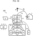
- Figs. 1A and 1B are diagrams illustrating an example of a power system according to an embodiment. The specific example of a first power converter 5 and a second power converter 12 of Fig. 1 are illustrated in Fig. 1B .
- a power system 100 includes a building 1, a power generation device 2, a storage battery 3, a hydrogen energy storage device 4, the first power converter 5, a grid 6, and a controller 20.
- the hydrogen energy storage device 4 includes the second power converter 12, a fuel cell 11, a hydrogen reservoir 10, and a water electrolyzer 9.
- the first power converter 5 includes, for example, a DC/DC converter 5A and a DC/AC converter 5B.
- the second power converter 12 includes, for example, a DC/DC converter 12C.
- a distribution board 7 in the building 1 is provided with a wattmeter 8.
- the power generation device 2 is a device that generates electricity using renewable energy.
- the power generation device 2 supplies, as required, the electric power generated by the power generation device 2, to the building 1, the storage battery 3, and the hydrogen energy storage device 4.
- the power generation device 2 may be of any type as long as it has such a power generation function.
- the power generation device 2 may include, for example, a solar cell. When the power generation device 2 is a solar cell, the power generation device 2 may be installed on the roof of the building 1.
- the storage battery 3 is a battery that can be used by repeating charge/discharge.
- the storage battery 3 supplies, as required, the electric power stored in the storage battery 3 to the building 1.
- the storage battery 3 may be of any type as long as it has such a power storage function.
- the water electrolyzer 9 is a device that generates hydrogen by electrolysis of water. Although not illustrated in the figure, equipment necessary for generating hydrogen in the water electrolyzer 9 is appropriately provided. For example, a water pump that supplies water to the water electrolyzer 9, an electrolyte membrane that conducts protons generated by electrolysis of water, and the like may be provided. In addition, a catalyst layer may be provided on each of the main surfaces of the electrolyte membrane. A voltage applying device that applies a voltage between these catalyst layers may be provided.
- the hydrogen reservoir 10 is a device that stores hydrogen generated by electrolysis of water in the water electrolyzer 9.
- the hydrogen reservoir 10 may have any configuration as long as it can store such hydrogen.
- the hydrogen reservoir 10 may include, for example, a tank.
- the fuel cell 11 is a device that generates electricity using hydrogen in the hydrogen reservoir 10 that stores hydrogen generated by the water electrolyzer 9.
- the fuel cell 11 supplies, as required, the electric power generated by the fuel cell 11 to the building 1.
- the fuel cell 11 may be of any type as long as it has such a power generation function.
- the fuel cell 11 may include, for example, a polymer electrolyte fuel cell, a solid oxide fuel cell, a phosphoric acid fuel cell and the like.
- the water electrolyzer 9 and the fuel cell 11 may be a reversible fuel cell having both functions of hydrogen production and power generation.
- the reversible fuel cell has a poor function, it is possible to make the reversible fuel cell compact. For example, by connecting the reversible fuel cell and the hydrogen reservoir 10, it is possible to store hydrogen by the hydrogen reservoir 10, and perform hydrogen production and power generation using hydrogen by the reversible fuel cell.
- the detector is a sensor that detects that there is a person in the building 1.
- the detector may be any sensor as long as it is a sensor that detects that there is a person in the building 1.
- the detector may be the wattmeter 8 that detects the electric power supplied from the distribution board 7 to the building 1.
- the detection signal of the wattmeter 8 is subjected to signal processing by an appropriate signal processing circuit (not illustrated), and then transmitted to the controller 20.
- Another example of the detector that detects that there is a person in the building 1 will be described in a modification.
- the controller 20 can determine whether there is a person in the building 1 based on whether the detection signal of the wattmeter 8 exceeds a given set value. That is, when the detection signal of the wattmeter 8 is equal to or less than the set value, it is determined that there is no person in the building 1, and when the detection signal of the wattmeter 8 exceeds the set value, it is determined that there is a person in the building 1.
- a plurality of the above set values be set for respective power lines in the distribution board 7, for example. That is, although it may be determined whether there is a person in the entire building 1, it is preferable to determine whether there is a person in each of the respective rooms or areas in the building 1.
- the controller 20 may determine whether there is a person in the building 1 due to a change in power.
- the controller 20 can determine that there is a person in the building 1.
- the boiling pot and its power consumption are examples, and the present modification is not limited to this example. Since a change in power consumption can be grasped in advance even when other electric devices are used, it can be determined whether there is a person in the building 1 due to the change in power consumption.
- the power generation device 2 and the storage battery 3 are connected to the DC/DC converter 5A of the first power converter 5 via wiring 2a and wiring 3a, respectively. Further, the DC/DC converter 5A of the first power converter 5 and the DC/AC converter 5B are connected to each other via internal wiring 5c, and a distribution line 6a of the grid 6 is connected to the DC/AC converter 5B via wiring 7a.
- the grid 6 is connected to the distribution board 7 via the distribution line 6a.
- the wattmeter 8 is connected by a connection line (not illustrated) so as to be able to receive one or a plurality of power signals in the distribution board 7.
- a distribution network (not illustrated) in the building 1 may be provided from the distribution board 7. That is, power lines are laid out from the distribution board 7 in a plurality of rooms or areas in the building 1, and the power consumption in each of these rooms or areas may be configured to be acquired by the wattmeter 8.
- the DC/DC converter 5A of the first power converter 5 and the DC/DC converter 12C of the second power converter 12 are connected to each other via wiring 4a.
- the water electrolyzer 9 and the fuel cell 11 are connected to the DC/DC converter 12C of the second power converter 12 via wiring 12a and wiring 12b, respectively.
- the water electrolyzer 9 is connected to the hydrogen reservoir 10 via piping 9a, and the hydrogen reservoir 10 is connected to the fuel cell 11 via piping 10a. In this way, it is possible to temporarily store the hydrogen generated by the water electrolyzer 9 in the hydrogen reservoir 10. In addition, such hydrogen can be supplied, in a timely manner, from the hydrogen reservoir 10 as a power generation material of the fuel cell 11.
- the electric power (direct current) generated by the power generation device 2 is supplied to the storage battery 3 via the DC/DC converter 5A of the first power converter 5, and is supplied to the water electrolyzer 9 via the DC/DC converter 5A of the first power converter 5 and the DC/DC converter 12C of the second power converter 12 in a timely manner.
- the storage battery 3 is charged. Further, hydrogen is produced through electrolysis of water by the water electrolyzer 9.
- the electric power (direct current) generated by the power generation device 2 is transmitted, in a timely manner, to the DC/DC converter 5A of the first power converter 5 and the DC/AC converter 5B of the first power converter 5 in this order, and is converted from DC to AC in the DC/AC converter 5B.
- the electric power (AC) from the DC/AC converter 5B is supplied to the distribution line 6a of the grid 6. In this way, the electric power generated by the power generation device 2 can be supplied to the distribution board 7 of the building 1 or can be flowed backwardly into the grid 6, as required.
- the electric power (direct current) discharged from the storage battery 3 is transmitted, in a timely manner, to the DC/DC converter 5A of the first power converter 5 and the DC/AC converter 5B of the first power converter 5 in this order, and is converted from DC to AC in the DC/AC converter 5B.
- the electric power (AC) from the DC/AC converter 5B is supplied to the distribution line 6a of the grid 6. In this way, the electric power discharged from the storage battery 3 can be supplied to the distribution board 7 of the building 1.
- the electric power (direct current) generated by the fuel cell 11 is transmitted to the DC/DC converter 12C of the second power converter 12, the DC/DC converter 5A of the first power converter 5, and the DC/AC converter 5B of the first power converter 5 in this order, and is converted from DC to AC in the DC/AC converter 5B.
- the electric power (AC) from the DC/AC converter 5B is supplied to the distribution line 6a of the grid 6. In this way, it is possible to supply the electric power generated by the fuel cell 11 to the distribution board 7 of the building 1.
- the controller 20 performs at least one of first control and second control.
- the first control determines the priority of the power supply from the power generation device 2 using renewable energy to each of the storage battery 3 and the water electrolyzer 9 based on the information detected by the wattmeter 8
- the second control determines the priority of the power supply from each of the storage battery 3 and the fuel cell 11 to the power load provided in the building 1 based on the information detected by the wattmeter 8.
- the controller 20 may control the overall operation of the power system 100.
- the controller 20 may have any configuration as long as the controller 20 has a control function.
- the controller 20 includes, for example, an arithmetic circuit (not illustrated) and a memory circuit (not illustrated) that stores a control program.
- the arithmetic circuit may include, for example, an MPU, a CPU, and the like.
- the memory circuit may include, for example, a memory.
- the controller 20 may be constituted by a single controller that performs centralized control, or may be constituted by a plurality of controllers that performs distributed control in cooperation with each other.
- the following operation may be performed so that the arithmetic circuit of the controller 20 is implemented by the control program from the memory circuit of the controller 20. However, it is not necessarily indispensable to perform the following operations by the controller 20. An operator may perform part of its operation.
- the power consumption of the power load is supplied from the first power converter 5 to the distribution board 7, and the surplus electric power out of the electric power generated by the power generation device 2 is, as required, supplied to one of the storage battery 3, the water electrolyzer 9, and the grid 6.
- first control of determining the priority of the power supply from the power generation device 2 to each of the storage battery 3 and the water electrolyzer 9 using renewable energy is performed based on the information detected by the wattmeter 8. A specific example of the first control will be described in the first example.
- the shortage of the power consumption of the power load is, as required, supplied to the distribution board 7 from at least one of the storage battery 3, the fuel cell 11, and the grid 6. Further, while the power generation of the power generation device 2 is stopped, the power consumption of the power load provided in the building 1 is, as required, supplied to the distribution board 7 from at least one of the storage battery 3, the fuel cell 11, and the grid 6.
- second control of determining the priority of the power supply from the storage battery 3 and the fuel cell 11 to the power load provided in the building 1 is performed based on the information detected by the wattmeter 8.
- a specific example of the second control will be described in the second example.
- the power system 100 of the present embodiment can appropriately store the electric power obtained from renewable energy in the storage battery 3 suitable for short-term energy storage and the water electrolyzer 9 suitable for long-term energy storage. In this way, highly efficient power control of the power system 100 is performed.
- the power system 100 of the present embodiment can appropriately supply the electric power to the power load provided in the building from the storage battery 3 suitable for short-term energy output and the fuel cell 11 suitable for long-term energy output. In this way, highly efficient power control of the power system 100 is performed.
- the power system 100 of the present embodiment is the same as the power system 100 of the embodiment except for the control by the controller 20 described below.
- the controller 20 in the first control described above, prioritizes the storage battery 3 over the water electrolyzer 9 to cause the storage battery 3 to receive the electric power from the power generation device 2 using renewable energy.
- the controller 20 in the first control described above, prioritizes the water electrolyzer 9 over the storage battery 3 to cause the water electrolyzer 9 to receive the electric power from the power generation device 2 using renewable energy.
- the storage battery 3 is prioritized over the water electrolyzer 9, and the storage battery 3 is charged (storage) up to the maximum electric power Wsix within the range of the surplus electric power Ws of the electric power generation device 2. That is, when the surplus electric power Ws is smaller than the maximum electric power Wsix (Ws ⁇ Wsix), the entire amount of surplus electric power Ws is supplied to the storage battery 3, and surplus electric power Ws is not supplied to the water electrolyzer 9.
- the reason for performing the above power control is as follows.
- the storage battery 3 capable of receiving high power with a higher energy conversion efficiency is prioritized over the water electrolyzer 9, and the storage battery 3 is caused to receive the surplus electric power Ws of the power generation device 2, so that the amount of electricity stored in the storage battery 3 is increased as much as possible, and it is possible to prepare for an increase in power consumption of the power load.
- the water electrolyzer 9 is prioritized over the storage battery 3, and the water electrolyzer 9 is caused to receive the electric power up to the maximum electric power Whix within the range of the surplus electric power Ws of the electric power generation device 2.
- the surplus electric power Ws is smaller than the maximum electric power Whix (Ws ⁇ Whix)
- the entire amount of the surplus electric power Ws is supplied to the water electrolyzer 9, and the surplus electric power Ws is not supplied to the storage battery 3.
- hydrogen produced by the water electrolyzer 9 is stored in the hydrogen reservoir 10, so that hydrogen storage (storage) is performed in the hydrogen energy storage device 4.
- the storage battery 3 is charged (storage) up to the maximum electric power Wsix within the range of the remaining electric power (Ws - Whix) of the surplus electric power Ws.
- the reason for performing the above power control is as follows.
- the detector When the detector does not detect that there is a person in the building 1, it is predicted that the power consumption of the power load provided in the building 1 will not increase for a while after this detection. That is, it is predicted that the period during which the surplus electric power Ws of the power generation device 2 is generated will continue for a while.
- the storage battery 3 having storage capacity smaller than that of the hydrogen energy storage device 4 (the water electrolyzer 9 and the hydrogen reservoir 10) is prioritized over the hydrogen energy storage device 4, and the storage battery 3 is caused to receive the power generated by the power generation device 2, the storage battery 3 may be fully charged at an early stage. As a result, in the remaining period during which the surplus electric power Ws of the power generation device 2 is generated, it is necessary to store hydrogen (power reception) using this surplus electric power Ws only by the water electrolyzer 9 having the smaller maximum electric power that can be received than the storage battery 3.
- the amount of electricity stored in the storage battery 3 and the hydrogen energy storage device 4 may decrease during the period in which the surplus electric power Ws of the power generation device 2 is generated.
- the amount of electricity stored in the hydrogen energy storage device 4 correspond to a value obtained by converting the amount of hydrogen stored in the hydrogen reservoir 10 by generating hydrogen by electrolysis of water by the water electrolyzer 9 using electric power as the amount of electricity generated by the fuel cell 11.
- the storage capacity of the hydrogen energy storage device 4 corresponds to a value obtained by converting the amount of hydrogen stored in the hydrogen reservoir 10 as the he amount of electricity generated by the fuel cell 11.
- the amount of electricity stored in the storage battery 3 and the hydrogen energy storage device 4 correspond to the sum of the charge amount of the storage battery 3 using the surplus electric power Ws of the power generation device 2, and the charge amount of the hydrogen energy storage device 4.
- the power system 100 priortizes the water electrolyzer 9 over the storage battery 3 when the wattmeter 8 does not detect that there is a person in the building 1, and causes the water electrolyzer 9 to receive the electric power generated by the power generation device 2, so that it is possible to extend the period before the storage battery 3 is fully charged.
- the period during which power is received by both the storage battery 3 and the water electrolyzer 9 among the period in which the surplus electric power Ws of the power generation device 2 is generated is extended. Therefore, the amount of electric power transmitted to the grid 6 can be reduced during the period in which the surplus electric power Ws of the power generation device 2 is generated.
- the power system 100 can increase the amount of electricity stored in the storage battery 3 and the hydrogen energy storage device 4 when the wattmeter 8 does not detect that there is a person in the building 1, compared with a case where the storage battery 3 is caused to preferentially receive the power generated by the power generation device 2.
- the power consumption of the power load provided in the building 1 is small and the continuity of the period in which the surplus electric power Ws is generated can be expected. Therefore, even if control is performed so that the water electrolyzer 9 preferentially receives the surplus electric power Ws, it is probable that the number of times of starting and stopping of the hydrogen energy storage device 4 be small, so that it is possible to suppress a decrease in the efficiency of the power system 100.
- the power system 100 of the present embodiment may be the same as the power system 100 of the embodiment except for the above features.
- the power system 100 of the present embodiment is the same as the power system 100 of the embodiment except for the control by the controller 20 described below.
- the controller 20 in the above-described second control, prioritizes the fuel cell 11 over the storage battery 3, and causes the fuel cell 11 to supply electric power to the power load provided in the building 1.
- the controller 20 in the above-described second control, prioritizes the storage battery 3 over the fuel cell 11, and causes the storage battery 3 to supply electric power to the power load provided in the building 1.
- the fuel cell 11 is prioritized over the storage battery 3, and the fuel cell 11 generates the power up to the maximum electric power Whox within the range of the power consumption W0 of the power load provided in the building 1. That is, when the power consumption W0 is smaller than the maximum electric power Whox (W0 ⁇ Whox), the entire amount of the power consumption W0 is generated by the fuel cell 11, and the storage battery 3 is not discharged.
- the storage battery 3 is discharged up to the maximum electric power Wsox within the range of the remaining power (W0 - Whox) of the power consumption W0.
- the reason for performing the above power control is as follows.
- the power system 100 can increase the electric power supplied from the storage battery 3 and the fuel cell 11 to the power load, compared with the case where the electric power is supplied to the power load preferentially from the storage battery 3. More detail in this regard will be described.
- the storage battery 3 has a small storage capacity, the storage battery 3 can output high power with high energy conversion efficiency, compared with the hydrogen energy storage device 4.
- the storage battery 3 is preferentially discharged, there is a possibility that the amount of electricity stored in the storage battery 3 becomes zero at an early stage.
- the power system 100 of the present embodiment causes the fuel cell 11 to preferentially generate the power.
- the supply of the base electric power out of the power consumption W0 of the power load from the fuel cell 11, and the supply of the short term fluctuating power out of electric power W0 of the power load from the storage battery 3 make it possible to increase the electric power supplied from both of them. In this way, it is possible to extend the period before the amount of electricity stored in the storage battery 3 becomes zero. As a result, is possible to increase the hydrogen consumption amount in the hydrogen reservoir 10 of the hydrogen energy storage device 4 in the remaining period. In other words, it is possible to increase the electric power to be supplied to the power load from the storage battery 3 and the fuel cell 11.
- the storage battery 3 is prioritized over the fuel cell 11, and the storage battery 3 is discharged up to the maximum electric power Wsox within the range of the power consumption W0 of the power load provided in the building 1. That is, when the power consumption W0 is smaller than the maximum electric power Wsox (W0 ⁇ Wsox), the entire amount of the power consumption W0 is covered by the discharge from the storage battery 3, and the fuel cell 11 does not generate the power.
- the fuel cell 11 when the power consumption W0 is larger than the maximum electric power Wsox (W0 > Wsox), the fuel cell 11 generates the power up to the maximum electric power Whox within the range of the remaining power (W0 - Wsox) of the power consumption W0.
- the reason for performing the above power control is as follows.
- the power consumption W0 of the power load provided in the building 1 will not increase for a while after this detection. That is, in this case, even if the electric power is supplied to the power load preferentially from the storage battery 3, it is possible to cover the power consumption W0 of the power load within the range of the storage capacity of the storage battery 3. At this time, if the electric power is supplied to the power load preferentially from the fuel cell 11, there is a possibility that intermittent low output and low efficiency operation in the fuel cell 11 is performed. However, the power system 100 of the present embodiment can reduce this possibility under the second control described above.
- the power system 100 according to the present embodiment may be the same as the power system 100 according to the embodiment or the first example of the embodiment except for the above-described features.
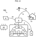
- Fig. 2 is a diagram illustrating an example of a power system according to a first modification of the embodiment.
- the power system 100 of Fig. 2 is the same as the power system 100 of Fig. 1A except that a human detection sensor 13 instead of the wattmeter 8 as a detector that detects that there is a person in the building 1 is used.
- the human detection sensor 13 is a sensor that detects a person.
- the human detection sensor 13 may include, for example, an infrared sensor, but it is not limited thereto.
- the human detection sensor 13 may be attached to the doorway of the building 1, or may be provided in an appropriate room in the building 1.
- Fig. 2 although only one room in the building 1 is illustrated, the human detection sensor 13 may be provided in each of the rooms in a case where there is a plurality of rooms in the building 1. In this case, although the detection accuracy of a person existing in the building 1 can be improved, cost effectiveness should be considered as the cost increases.
- the controller 20 can determine whether there is a person in the building 1.
- the power system 100 according to the present modification may be the same as the power system 100 according to any of the embodiment, the first example of the embodiment, and the second example of the embodiment except for the above-described features. That is, as in the power system 100 according to any of the embodiment, the first example of the embodiment, and the second example of the embodiment, the power system 100 of the present modification performs highly efficient power control by executing at least one of the first control and the second control.
- Fig. 3 is a diagram illustrating an example of a power system according to a second modification of the embodiment.
- the power system 100 of Fig. 3 is the same as the power system 100 of Fig. 1A except that a CO 2 gas sensor 15 instead of the wattmeter 8 as a detector that detects that there is a person in the building 1 is used.
- the CO 2 gas sensor 15 is provided at an appropriate position in the building 1, and is a sensor that detects CO 2 generated by human breathing.
- the CO 2 gas sensor 15 is often provided, for example, to appropriately adjust the CO 2 concentration in the room of the building 1 with a ventilation facility.
- the CO 2 gas sensor 15 may be provided in each of the rooms in a case where there is a plurality of rooms in the building 1. In this case, although the detection accuracy of a person existing in the building 1 can be improved, cost effectiveness should be considered as the cost increases.
- CO 2 concentration rises due to human breathing.
- CO 2 concentration measured by the CO 2 gas sensor 15 exceeds a predetermined set value, a predetermined signal is generated in the CO2 gas sensor 15.
- the detection signal of the CO 2 gas sensor 15 is subjected to signal processing by an appropriate signal processing circuit (not illustrated), and then transmitted to the controller 20 in a timely manner. In this way, the controller 20 can determine whether there is a person in the building 1.
- the CO 2 concentration in the air is about 400 ppm or less, for example, the CO2 concentration of about 500 ppm to 1000 ppm may be used as the above set value. Note that this set value is an example, and is not limited to this example.
- the infrared sensor which is an example of the human detection sensor 13 of the first modification, it is difficult to detect that there is a person in the building 1, for example, if there is no person on the infrared due to furniture in the room or complicated construction.
- the CO 2 gas sensor 15 can properly detect that there is a person in the building 1 unless the CO 2 gas sensor 15 and the person are spatially obstructed.
- the power system 100 according to the present modification may be the same as the power system 100 according to any of the embodiment, the first example of the embodiment, and the second example of the embodiment except for the above-described features. That is, as in the power system 100 according to any of the embodiment, the first example of the embodiment, and the second example of the embodiment, the power system 100 of the present modification performs highly efficient power control by executing at least one of the first control and the second control.
- Fig. 4 is a diagram illustrating an example of a power system according to a third modification of the embodiment.
- the power system 100 of Fig. 4 is the same as the power system 100 of Fig. 1A except that a vibration sensor 17 instead of the wattmeter 8 as a detector that detects that there is a person in the building 1 is used.
- the vibration sensor 17 is provided on the floor of the building 1, and is a sensor that detects a vibration occurring in the building 1 due to human walking or the like.
- the vibration sensor 17 may have any configuration as long as the vibration sensor 17 is a sensor for picking up and detecting the vibration of the floor of the building 1.
- the vibration sensor 17 may be a contact vibration sensor, or a non-contact vibration sensor.
- the contact vibration sensor may include, for example, a piezoelectric element, a electromagnetic sensor, or the like, but not limited thereto.
- the non-contact vibration sensor may include, for example, an electrostatic capacity sensor, an eddy current sensor, a laser Doppler sensor or the like, but not limited thereto. In Fig.
- the vibration sensor 17 may be provided in each of the rooms in a case where there is a plurality of rooms in the building 1. In this case, the detection accuracy of a person existing in the building 1 can be improved. For example, if there is only one vibration sensor 17, it is necessary to detect a vibration caused by walking of a person through the entire building 1 with a single vibration sensor 17. For this reason, when a person is present at a position away from the vibration sensor 17, only low-level slight vibration is transmitted to the vibration sensor 17, so that the controller 20 may erroneously determine that a person is not present in the building 1. However, since the installation of the plurality of vibration sensors 17 increases the cost, cost effectiveness should be considered.
- the vibration occurs on the floor of the building 1.
- a predetermined signal is generated in the vibration sensor 17.
- the detection signal of the vibration sensor 17 is subjected to signal processing by an appropriate signal processing circuit (not illustrated), and then transmitted to the controller 20. In this way, the controller 20 can determine whether there is a person in the building 1.
- the above set value is set as a threshold value in order not to erroneously detect such a minute vibration by the vibration sensor 17.
- the vibration sensor 17 can properly detect that there is a person in the building 1 as long as the vibration due to walking of a person is propagated to the vibration sensor 17.
- the vibration due to walking of a person has various characteristics such as an acceleration, a displacement amount and a frequency. Therefore, it is possible to learn the action of a person in the building 1, the attribute of a person such as an adult or a child based on the analysis of the characteristics of the vibration detected by the vibration sensor 17.
- the power system 100 according to the present modification may be the same as the power system 100 according to any of the embodiment, the first example of the embodiment, and the second example of the embodiment except for the above-described features. That is, as in the power system 100 according to any of the embodiment, the first example of the embodiment, and the second example of the embodiment, the power system 100 of the present modification performs highly efficient power control by executing at least one of the first control and the second control.
- the embodiments, the first example to the second example of the embodiment, and the first modification to the third modification of the embodiment may be combined with each other unless mutually is excluded.
- the controller 20 may receive a signal indicating the presence or absence of a person in the building 1 from equipment having an interface with a person by connecting the device with an energy management system (EMS), a home hub, or the like.
- EMS energy management system
- the equipment having an interface with a person may include, for example, information terminals such as a smartphone, a tablet terminal, and a personal computer.
Landscapes
- Engineering & Computer Science (AREA)
- Power Engineering (AREA)
- General Chemical & Material Sciences (AREA)
- Electromagnetism (AREA)
- Sustainable Energy (AREA)
- Chemical & Material Sciences (AREA)
- Chemical Kinetics & Catalysis (AREA)
- Electrochemistry (AREA)
- Life Sciences & Earth Sciences (AREA)
- Manufacturing & Machinery (AREA)
- Physics & Mathematics (AREA)
- Sustainable Development (AREA)
- General Physics & Mathematics (AREA)
- Radar, Positioning & Navigation (AREA)
- Automation & Control Theory (AREA)
- Fuel Cell (AREA)
- Supply And Distribution Of Alternating Current (AREA)
- Electrolytic Production Of Non-Metals, Compounds, Apparatuses Therefor (AREA)
- Charge And Discharge Circuits For Batteries Or The Like (AREA)
Applications Claiming Priority (1)
| Application Number | Priority Date | Filing Date | Title |
|---|---|---|---|
| JP2018080689 | 2018-04-19 |
Publications (2)
| Publication Number | Publication Date |
|---|---|
| EP3557715A1 true EP3557715A1 (de) | 2019-10-23 |
| EP3557715B1 EP3557715B1 (de) | 2021-01-13 |
Family
ID=65911061
Family Applications (1)
| Application Number | Title | Priority Date | Filing Date |
|---|---|---|---|
| EP19164848.4A Active EP3557715B1 (de) | 2018-04-19 | 2019-03-25 | Leistungssystem |
Country Status (3)
| Country | Link |
|---|---|
| US (1) | US11152788B2 (de) |
| EP (1) | EP3557715B1 (de) |
| JP (1) | JP7417972B2 (de) |
Cited By (1)
| Publication number | Priority date | Publication date | Assignee | Title |
|---|---|---|---|---|
| CN110518865A (zh) * | 2019-08-09 | 2019-11-29 | 华南理工大学 | 一种风电-光电耦合的工业规模稳定供氢系统 |
Families Citing this family (9)
| Publication number | Priority date | Publication date | Assignee | Title |
|---|---|---|---|---|
| CN113424342A (zh) * | 2019-02-12 | 2021-09-21 | 松下知识产权经营株式会社 | 电力供给系统、电力供给系统的控制装置以及控制方法 |
| JP7590706B2 (ja) * | 2020-01-23 | 2024-11-27 | 東京電力ホールディングス株式会社 | エネルギー管理システム、エネルギー管理装置、エネルギー管理方法、及び制御プログラム |
| JP7441121B2 (ja) * | 2020-06-05 | 2024-02-29 | 本田技研工業株式会社 | 電力調整システム、電力調整方法、及びプログラム |
| JP7610938B2 (ja) * | 2020-08-31 | 2025-01-09 | 株式会社神戸製鋼所 | 電力制御システム及びこれを用いた水素製造設備 |
| JP2023009768A (ja) * | 2021-07-08 | 2023-01-20 | 誠 梅谷 | 水素製造装置 |
| WO2023069316A1 (en) * | 2021-10-21 | 2023-04-27 | 8Me Nova, Llc | Systems and methods for renewable powerplant serving multiple loads |
| US12119646B2 (en) | 2021-10-21 | 2024-10-15 | 8Me Nova, Llc | Systems and methods for renewable powerplant serving multiple loads |
| US20230202315A1 (en) * | 2021-12-27 | 2023-06-29 | Newton Howard | Hydrogen-based power storage unit |
| JP2024034267A (ja) * | 2022-08-31 | 2024-03-13 | 高砂熱学工業株式会社 | エネルギーマネジメントシステム、エネルギー管理方法及びプログラム |
Citations (7)
| Publication number | Priority date | Publication date | Assignee | Title |
|---|---|---|---|---|
| JPS5547902B2 (de) | 1977-09-07 | 1980-12-03 | ||
| JP2006236741A (ja) * | 2005-02-24 | 2006-09-07 | Sanesu Denki Tsushin Kk | 自然エネルギーを有効利用する発電システム, |
| US20090076661A1 (en) * | 2007-07-25 | 2009-03-19 | Ken Pearson | Apparatus, system, and method to manage the generation and use of hybrid electric power |
| US20090189445A1 (en) * | 2008-01-24 | 2009-07-30 | Renewable Energy Holdings, Llc | Renewable energy management and storage system |
| JP2010233362A (ja) * | 2009-03-27 | 2010-10-14 | Toyota Motor Corp | 電力供給制御装置 |
| WO2017089468A1 (de) * | 2015-11-25 | 2017-06-01 | Hps Home Power Solutions Gmbh | Hausenergieanlage und betriebsverfahren zum betreiben einer hausenergieanlage |
| JP6189448B2 (ja) | 2015-07-21 | 2017-08-30 | 株式会社東芝 | 電力供給システム、制御装置、および電力供給方法 |
Family Cites Families (30)
| Publication number | Priority date | Publication date | Assignee | Title |
|---|---|---|---|---|
| JP3295185B2 (ja) * | 1993-09-09 | 2002-06-24 | 光洋精工株式会社 | 軸受の異常検出装置 |
| US6559621B2 (en) * | 2001-05-21 | 2003-05-06 | Cellex Power Products, Inc. | Hybrid energy storage device charge equalization system and method |
| JP2003209994A (ja) * | 2002-01-15 | 2003-07-25 | Nippon Telegr & Teleph Corp <Ntt> | 発電システムおよびその制御方法 |
| US6674263B2 (en) * | 2002-06-05 | 2004-01-06 | Kodjo Agbossou | Control system for a renewable energy system |
| US7119458B2 (en) * | 2002-10-01 | 2006-10-10 | Mti Microfuel Cells, Inc. | A/C—D/C power system with internal fuel cell |
| JP4768216B2 (ja) * | 2003-06-03 | 2011-09-07 | 株式会社日立製作所 | 学習制御を有する燃料電池発電システム |
| US7187280B2 (en) * | 2003-07-31 | 2007-03-06 | Techko, Inc. | Alarm system with thin profile |
| US8019445B2 (en) * | 2004-06-15 | 2011-09-13 | Intelligent Generation Llc | Method and apparatus for optimization of distributed generation |
| US7274975B2 (en) * | 2005-06-06 | 2007-09-25 | Gridpoint, Inc. | Optimized energy management system |
| JP2007067312A (ja) * | 2005-09-02 | 2007-03-15 | Jipangu Energy:Kk | 太陽光利用の給電システム |
| TWI474694B (zh) * | 2006-02-22 | 2015-02-21 | Koninkl Philips Electronics Nv | 於展頻快速無線電網路中用於安靜期管理的二階架構之系統、裝置及方法 |
| JP4721949B2 (ja) * | 2006-04-28 | 2011-07-13 | 大阪瓦斯株式会社 | ロードサーベイシステム |
| US20100017045A1 (en) * | 2007-11-30 | 2010-01-21 | Johnson Controls Technology Company | Electrical demand response using energy storage in vehicles and buildings |
| US8823277B2 (en) * | 2008-04-14 | 2014-09-02 | Digital Lumens Incorporated | Methods, systems, and apparatus for mapping a network of lighting fixtures with light module identification |
| US8315745B2 (en) * | 2009-04-24 | 2012-11-20 | Hunter Defense Technologies, Inc. | Mobile micro-grid power system controller and method |
| JP5421847B2 (ja) * | 2010-04-27 | 2014-02-19 | 積水化学工業株式会社 | 予測表示サーバ及び予測表示システム |
| FR2972867B1 (fr) * | 2011-03-17 | 2014-02-07 | Cassidian Sas | Systeme d'alimentation electrique hybride autonome d'un equipement electrique et unite et procede de gestion du systeme |
| JP5874311B2 (ja) * | 2011-10-24 | 2016-03-02 | ソニー株式会社 | 電力需要予測装置、電力需要予測方法および電力需要予測システム |
| US9408268B2 (en) * | 2012-06-19 | 2016-08-02 | Wireless Environment, Llc | Group management of a wireless power outage lighting system |
| US20140062692A1 (en) * | 2012-09-05 | 2014-03-06 | Honeywell Inernational Inc. | Motion Detector with Shock Detection |
| JP2014082867A (ja) * | 2012-10-16 | 2014-05-08 | Toshiba Corp | 電源制御システム、制御装置及び制御方法 |
| JP6076799B2 (ja) * | 2013-03-28 | 2017-02-08 | 大和ハウス工業株式会社 | 試算装置及び試算方法 |
| EP2869377A1 (de) * | 2013-10-29 | 2015-05-06 | Total Marketing Services | Energieerzeugungssystem |
| JP2015139066A (ja) * | 2014-01-21 | 2015-07-30 | 株式会社デンソー | 在不在判定装置 |
| JP6635654B2 (ja) * | 2014-03-04 | 2020-01-29 | キヤノンメディカルシステムズ株式会社 | ワイヤレスフットスイッチ及びx線診断システム |
| JP5866079B1 (ja) * | 2014-11-12 | 2016-02-17 | 株式会社東芝 | 電力供給システム |
| CN107431220B (zh) * | 2015-12-22 | 2021-06-29 | 慧与发展有限责任合伙企业 | 管理数据中心电子部件的装置,及相关系统和方法 |
| KR102693433B1 (ko) * | 2016-10-26 | 2024-08-09 | 삼성전자주식회사 | 전자 장치 및 그의 동작을 제어하는 방법 |
| DE102017000441A1 (de) * | 2017-01-19 | 2018-07-19 | e.solutions GmbH | Eingabevorrichtung und Verfahren zum Erfassen einer Eingabe |
| US20180375444A1 (en) * | 2017-06-23 | 2018-12-27 | Johnson Controls Technology Company | Building system with vibration based occupancy sensors |
-
2019
- 2019-02-26 JP JP2019032703A patent/JP7417972B2/ja active Active
- 2019-03-25 EP EP19164848.4A patent/EP3557715B1/de active Active
- 2019-04-02 US US16/373,031 patent/US11152788B2/en active Active
Patent Citations (7)
| Publication number | Priority date | Publication date | Assignee | Title |
|---|---|---|---|---|
| JPS5547902B2 (de) | 1977-09-07 | 1980-12-03 | ||
| JP2006236741A (ja) * | 2005-02-24 | 2006-09-07 | Sanesu Denki Tsushin Kk | 自然エネルギーを有効利用する発電システム, |
| US20090076661A1 (en) * | 2007-07-25 | 2009-03-19 | Ken Pearson | Apparatus, system, and method to manage the generation and use of hybrid electric power |
| US20090189445A1 (en) * | 2008-01-24 | 2009-07-30 | Renewable Energy Holdings, Llc | Renewable energy management and storage system |
| JP2010233362A (ja) * | 2009-03-27 | 2010-10-14 | Toyota Motor Corp | 電力供給制御装置 |
| JP6189448B2 (ja) | 2015-07-21 | 2017-08-30 | 株式会社東芝 | 電力供給システム、制御装置、および電力供給方法 |
| WO2017089468A1 (de) * | 2015-11-25 | 2017-06-01 | Hps Home Power Solutions Gmbh | Hausenergieanlage und betriebsverfahren zum betreiben einer hausenergieanlage |
Cited By (2)
| Publication number | Priority date | Publication date | Assignee | Title |
|---|---|---|---|---|
| CN110518865A (zh) * | 2019-08-09 | 2019-11-29 | 华南理工大学 | 一种风电-光电耦合的工业规模稳定供氢系统 |
| CN110518865B (zh) * | 2019-08-09 | 2021-07-20 | 华南理工大学 | 一种风电-光电耦合的工业规模稳定供氢系统 |
Also Published As
| Publication number | Publication date |
|---|---|
| US20190326754A1 (en) | 2019-10-24 |
| JP2019193557A (ja) | 2019-10-31 |
| US11152788B2 (en) | 2021-10-19 |
| EP3557715B1 (de) | 2021-01-13 |
| JP7417972B2 (ja) | 2024-01-19 |
Similar Documents
| Publication | Publication Date | Title |
|---|---|---|
| EP3557715B1 (de) | Leistungssystem | |
| JP6923231B2 (ja) | 直流バス制御システム | |
| EP2648304B1 (de) | Stromversorgungsvorrichtung, Stromversorgungsverfahren | |
| EP3206276B1 (de) | Energiespeichersystem und verwaltungsverfahren davon | |
| CN102308452B (zh) | 用于控制混合功率系统的方法和装置 | |
| US8982590B2 (en) | Solar generation method and system | |
| JP5729764B2 (ja) | 集合住宅電力システム及び制御装置 | |
| JP7710243B2 (ja) | 直流バス制御システム | |
| KR20160001249A (ko) | 태양광 발전과 에너지 저장 시스템을 이용한 홈 에너지 관리 시스템 | |
| JPWO2012086572A1 (ja) | 電力制御システムとその電力制御方法、およびパワーゲートウェイ装置とその電力制御方法 | |
| JP5592772B2 (ja) | 電力供給制御装置及びそれを用いた電力供給システム | |
| JP2007087829A (ja) | レドックスフロー電池システム | |
| JP6522901B2 (ja) | 直流配電システム | |
| KR20140080567A (ko) | 배터리 운용 시스템 및 운용 방법 | |
| JP7664638B2 (ja) | 直流バス制御システム | |
| US9929571B1 (en) | Integrated energy storage system | |
| CN206364523U (zh) | 一种伙伴充电控制系统和移动设备 | |
| CN118889560B (zh) | 一种融合电氢氨的微电网系统的功率分配控制方法及设备 | |
| KR20130123749A (ko) | 전력저장 장치 충전 시스템, 이에 적용되는 전력운송 차량 및 전력저장 장치 충전 시스템을 이용한 전력저장 장치의 충전 방법 | |
| CN208028849U (zh) | 一种太阳能热水检测系统 | |
| CN220086965U (zh) | 一种用于氢燃料电池的多级储能系统 | |
| Shimomachi et al. | Fuel cell and Electrolyzer System for Supply and Demand Balancing in DC | |
| US20240250545A1 (en) | Portable energy system | |
| CN111064178B (zh) | 一种自律式浮动微电网系统及其控制方法 | |
| JP2014090653A (ja) | 給電装置 |
Legal Events
| Date | Code | Title | Description |
|---|---|---|---|
| PUAI | Public reference made under article 153(3) epc to a published international application that has entered the european phase |
Free format text: ORIGINAL CODE: 0009012 |
|
| STAA | Information on the status of an ep patent application or granted ep patent |
Free format text: STATUS: THE APPLICATION HAS BEEN PUBLISHED |
|
| AK | Designated contracting states |
Kind code of ref document: A1 Designated state(s): AL AT BE BG CH CY CZ DE DK EE ES FI FR GB GR HR HU IE IS IT LI LT LU LV MC MK MT NL NO PL PT RO RS SE SI SK SM TR |
|
| AX | Request for extension of the european patent |
Extension state: BA ME |
|
| STAA | Information on the status of an ep patent application or granted ep patent |
Free format text: STATUS: REQUEST FOR EXAMINATION WAS MADE |
|
| 17P | Request for examination filed |
Effective date: 20200409 |
|
| RBV | Designated contracting states (corrected) |
Designated state(s): AL AT BE BG CH CY CZ DE DK EE ES FI FR GB GR HR HU IE IS IT LI LT LU LV MC MK MT NL NO PL PT RO RS SE SI SK SM TR |
|
| GRAP | Despatch of communication of intention to grant a patent |
Free format text: ORIGINAL CODE: EPIDOSNIGR1 |
|
| STAA | Information on the status of an ep patent application or granted ep patent |
Free format text: STATUS: GRANT OF PATENT IS INTENDED |
|
| RIC1 | Information provided on ipc code assigned before grant |
Ipc: H02J 3/38 20060101ALI20200721BHEP Ipc: H02J 3/32 20060101AFI20200721BHEP |
|
| INTG | Intention to grant announced |
Effective date: 20200810 |
|
| RIN1 | Information on inventor provided before grant (corrected) |
Inventor name: TAKAHASHI, YASUFUMI Inventor name: SHIMIZU, ATSUSHI Inventor name: ITO, TOMOKI |
|
| GRAS | Grant fee paid |
Free format text: ORIGINAL CODE: EPIDOSNIGR3 |
|
| GRAA | (expected) grant |
Free format text: ORIGINAL CODE: 0009210 |
|
| STAA | Information on the status of an ep patent application or granted ep patent |
Free format text: STATUS: THE PATENT HAS BEEN GRANTED |
|
| AK | Designated contracting states |
Kind code of ref document: B1 Designated state(s): AL AT BE BG CH CY CZ DE DK EE ES FI FR GB GR HR HU IE IS IT LI LT LU LV MC MK MT NL NO PL PT RO RS SE SI SK SM TR |
|
| REG | Reference to a national code |
Ref country code: GB Ref legal event code: FG4D |
|
| REG | Reference to a national code |
Ref country code: CH Ref legal event code: EP |
|
| REG | Reference to a national code |
Ref country code: IE Ref legal event code: FG4D |
|
| REG | Reference to a national code |
Ref country code: DE Ref legal event code: R096 Ref document number: 602019002124 Country of ref document: DE |
|
| REG | Reference to a national code |
Ref country code: AT Ref legal event code: REF Ref document number: 1355269 Country of ref document: AT Kind code of ref document: T Effective date: 20210215 |
|
| REG | Reference to a national code |
Ref country code: AT Ref legal event code: MK05 Ref document number: 1355269 Country of ref document: AT Kind code of ref document: T Effective date: 20210113 |
|
| REG | Reference to a national code |
Ref country code: NL Ref legal event code: MP Effective date: 20210113 |
|
| REG | Reference to a national code |
Ref country code: LT Ref legal event code: MG9D |
|
| PG25 | Lapsed in a contracting state [announced via postgrant information from national office to epo] |
Ref country code: FI Free format text: LAPSE BECAUSE OF FAILURE TO SUBMIT A TRANSLATION OF THE DESCRIPTION OR TO PAY THE FEE WITHIN THE PRESCRIBED TIME-LIMIT Effective date: 20210113 Ref country code: GR Free format text: LAPSE BECAUSE OF FAILURE TO SUBMIT A TRANSLATION OF THE DESCRIPTION OR TO PAY THE FEE WITHIN THE PRESCRIBED TIME-LIMIT Effective date: 20210414 Ref country code: HR Free format text: LAPSE BECAUSE OF FAILURE TO SUBMIT A TRANSLATION OF THE DESCRIPTION OR TO PAY THE FEE WITHIN THE PRESCRIBED TIME-LIMIT Effective date: 20210113 Ref country code: BG Free format text: LAPSE BECAUSE OF FAILURE TO SUBMIT A TRANSLATION OF THE DESCRIPTION OR TO PAY THE FEE WITHIN THE PRESCRIBED TIME-LIMIT Effective date: 20210413 Ref country code: NO Free format text: LAPSE BECAUSE OF FAILURE TO SUBMIT A TRANSLATION OF THE DESCRIPTION OR TO PAY THE FEE WITHIN THE PRESCRIBED TIME-LIMIT Effective date: 20210413 Ref country code: PT Free format text: LAPSE BECAUSE OF FAILURE TO SUBMIT A TRANSLATION OF THE DESCRIPTION OR TO PAY THE FEE WITHIN THE PRESCRIBED TIME-LIMIT Effective date: 20210513 Ref country code: LT Free format text: LAPSE BECAUSE OF FAILURE TO SUBMIT A TRANSLATION OF THE DESCRIPTION OR TO PAY THE FEE WITHIN THE PRESCRIBED TIME-LIMIT Effective date: 20210113 |
|
| PG25 | Lapsed in a contracting state [announced via postgrant information from national office to epo] |
Ref country code: SE Free format text: LAPSE BECAUSE OF FAILURE TO SUBMIT A TRANSLATION OF THE DESCRIPTION OR TO PAY THE FEE WITHIN THE PRESCRIBED TIME-LIMIT Effective date: 20210113 Ref country code: PL Free format text: LAPSE BECAUSE OF FAILURE TO SUBMIT A TRANSLATION OF THE DESCRIPTION OR TO PAY THE FEE WITHIN THE PRESCRIBED TIME-LIMIT Effective date: 20210113 Ref country code: LV Free format text: LAPSE BECAUSE OF FAILURE TO SUBMIT A TRANSLATION OF THE DESCRIPTION OR TO PAY THE FEE WITHIN THE PRESCRIBED TIME-LIMIT Effective date: 20210113 Ref country code: RS Free format text: LAPSE BECAUSE OF FAILURE TO SUBMIT A TRANSLATION OF THE DESCRIPTION OR TO PAY THE FEE WITHIN THE PRESCRIBED TIME-LIMIT Effective date: 20210113 Ref country code: AT Free format text: LAPSE BECAUSE OF FAILURE TO SUBMIT A TRANSLATION OF THE DESCRIPTION OR TO PAY THE FEE WITHIN THE PRESCRIBED TIME-LIMIT Effective date: 20210113 |
|
| PG25 | Lapsed in a contracting state [announced via postgrant information from national office to epo] |
Ref country code: IS Free format text: LAPSE BECAUSE OF FAILURE TO SUBMIT A TRANSLATION OF THE DESCRIPTION OR TO PAY THE FEE WITHIN THE PRESCRIBED TIME-LIMIT Effective date: 20210513 |
|
| REG | Reference to a national code |
Ref country code: DE Ref legal event code: R097 Ref document number: 602019002124 Country of ref document: DE |
|
| PG25 | Lapsed in a contracting state [announced via postgrant information from national office to epo] |
Ref country code: EE Free format text: LAPSE BECAUSE OF FAILURE TO SUBMIT A TRANSLATION OF THE DESCRIPTION OR TO PAY THE FEE WITHIN THE PRESCRIBED TIME-LIMIT Effective date: 20210113 Ref country code: CZ Free format text: LAPSE BECAUSE OF FAILURE TO SUBMIT A TRANSLATION OF THE DESCRIPTION OR TO PAY THE FEE WITHIN THE PRESCRIBED TIME-LIMIT Effective date: 20210113 Ref country code: MC Free format text: LAPSE BECAUSE OF FAILURE TO SUBMIT A TRANSLATION OF THE DESCRIPTION OR TO PAY THE FEE WITHIN THE PRESCRIBED TIME-LIMIT Effective date: 20210113 Ref country code: SM Free format text: LAPSE BECAUSE OF FAILURE TO SUBMIT A TRANSLATION OF THE DESCRIPTION OR TO PAY THE FEE WITHIN THE PRESCRIBED TIME-LIMIT Effective date: 20210113 |
|
| PLBE | No opposition filed within time limit |
Free format text: ORIGINAL CODE: 0009261 |
|
| STAA | Information on the status of an ep patent application or granted ep patent |
Free format text: STATUS: NO OPPOSITION FILED WITHIN TIME LIMIT |
|
| PG25 | Lapsed in a contracting state [announced via postgrant information from national office to epo] |
Ref country code: RO Free format text: LAPSE BECAUSE OF FAILURE TO SUBMIT A TRANSLATION OF THE DESCRIPTION OR TO PAY THE FEE WITHIN THE PRESCRIBED TIME-LIMIT Effective date: 20210113 Ref country code: SK Free format text: LAPSE BECAUSE OF FAILURE TO SUBMIT A TRANSLATION OF THE DESCRIPTION OR TO PAY THE FEE WITHIN THE PRESCRIBED TIME-LIMIT Effective date: 20210113 Ref country code: DK Free format text: LAPSE BECAUSE OF FAILURE TO SUBMIT A TRANSLATION OF THE DESCRIPTION OR TO PAY THE FEE WITHIN THE PRESCRIBED TIME-LIMIT Effective date: 20210113 |
|
| REG | Reference to a national code |
Ref country code: BE Ref legal event code: MM Effective date: 20210331 |
|
| 26N | No opposition filed |
Effective date: 20211014 |
|
| PG25 | Lapsed in a contracting state [announced via postgrant information from national office to epo] |
Ref country code: AL Free format text: LAPSE BECAUSE OF FAILURE TO SUBMIT A TRANSLATION OF THE DESCRIPTION OR TO PAY THE FEE WITHIN THE PRESCRIBED TIME-LIMIT Effective date: 20210113 Ref country code: IE Free format text: LAPSE BECAUSE OF NON-PAYMENT OF DUE FEES Effective date: 20210325 Ref country code: LU Free format text: LAPSE BECAUSE OF NON-PAYMENT OF DUE FEES Effective date: 20210325 Ref country code: FR Free format text: LAPSE BECAUSE OF NON-PAYMENT OF DUE FEES Effective date: 20210331 Ref country code: ES Free format text: LAPSE BECAUSE OF FAILURE TO SUBMIT A TRANSLATION OF THE DESCRIPTION OR TO PAY THE FEE WITHIN THE PRESCRIBED TIME-LIMIT Effective date: 20210113 |
|
| PG25 | Lapsed in a contracting state [announced via postgrant information from national office to epo] |
Ref country code: SI Free format text: LAPSE BECAUSE OF FAILURE TO SUBMIT A TRANSLATION OF THE DESCRIPTION OR TO PAY THE FEE WITHIN THE PRESCRIBED TIME-LIMIT Effective date: 20210113 |
|
| PG25 | Lapsed in a contracting state [announced via postgrant information from national office to epo] |
Ref country code: IT Free format text: LAPSE BECAUSE OF FAILURE TO SUBMIT A TRANSLATION OF THE DESCRIPTION OR TO PAY THE FEE WITHIN THE PRESCRIBED TIME-LIMIT Effective date: 20210113 |
|
| PG25 | Lapsed in a contracting state [announced via postgrant information from national office to epo] |
Ref country code: IS Free format text: LAPSE BECAUSE OF FAILURE TO SUBMIT A TRANSLATION OF THE DESCRIPTION OR TO PAY THE FEE WITHIN THE PRESCRIBED TIME-LIMIT Effective date: 20210513 |
|
| PG25 | Lapsed in a contracting state [announced via postgrant information from national office to epo] |
Ref country code: BE Free format text: LAPSE BECAUSE OF NON-PAYMENT OF DUE FEES Effective date: 20210331 |
|
| REG | Reference to a national code |
Ref country code: CH Ref legal event code: PL |
|
| PG25 | Lapsed in a contracting state [announced via postgrant information from national office to epo] |
Ref country code: LI Free format text: LAPSE BECAUSE OF NON-PAYMENT OF DUE FEES Effective date: 20220331 Ref country code: CH Free format text: LAPSE BECAUSE OF NON-PAYMENT OF DUE FEES Effective date: 20220331 |
|
| PG25 | Lapsed in a contracting state [announced via postgrant information from national office to epo] |
Ref country code: CY Free format text: LAPSE BECAUSE OF FAILURE TO SUBMIT A TRANSLATION OF THE DESCRIPTION OR TO PAY THE FEE WITHIN THE PRESCRIBED TIME-LIMIT Effective date: 20210113 Ref country code: NL Free format text: LAPSE BECAUSE OF NON-PAYMENT OF DUE FEES Effective date: 20210113 |
|
| PG25 | Lapsed in a contracting state [announced via postgrant information from national office to epo] |
Ref country code: HU Free format text: LAPSE BECAUSE OF FAILURE TO SUBMIT A TRANSLATION OF THE DESCRIPTION OR TO PAY THE FEE WITHIN THE PRESCRIBED TIME-LIMIT; INVALID AB INITIO Effective date: 20190325 |
|
| GBPC | Gb: european patent ceased through non-payment of renewal fee |
Effective date: 20230325 |
|
| PG25 | Lapsed in a contracting state [announced via postgrant information from national office to epo] |
Ref country code: GB Free format text: LAPSE BECAUSE OF NON-PAYMENT OF DUE FEES Effective date: 20230325 |
|
| PG25 | Lapsed in a contracting state [announced via postgrant information from national office to epo] |
Ref country code: GB Free format text: LAPSE BECAUSE OF NON-PAYMENT OF DUE FEES Effective date: 20230325 |
|
| PG25 | Lapsed in a contracting state [announced via postgrant information from national office to epo] |
Ref country code: MK Free format text: LAPSE BECAUSE OF FAILURE TO SUBMIT A TRANSLATION OF THE DESCRIPTION OR TO PAY THE FEE WITHIN THE PRESCRIBED TIME-LIMIT Effective date: 20210113 |
|
| PG25 | Lapsed in a contracting state [announced via postgrant information from national office to epo] |
Ref country code: TR Free format text: LAPSE BECAUSE OF FAILURE TO SUBMIT A TRANSLATION OF THE DESCRIPTION OR TO PAY THE FEE WITHIN THE PRESCRIBED TIME-LIMIT Effective date: 20210113 |
|
| PG25 | Lapsed in a contracting state [announced via postgrant information from national office to epo] |
Ref country code: MT Free format text: LAPSE BECAUSE OF FAILURE TO SUBMIT A TRANSLATION OF THE DESCRIPTION OR TO PAY THE FEE WITHIN THE PRESCRIBED TIME-LIMIT Effective date: 20210113 |
|
| PGFP | Annual fee paid to national office [announced via postgrant information from national office to epo] |
Ref country code: DE Payment date: 20260319 Year of fee payment: 8 |