EP3557071A1 - Pompe à vide et procédé de fonctionnement d'une telle pompe à vide - Google Patents
Pompe à vide et procédé de fonctionnement d'une telle pompe à vide Download PDFInfo
- Publication number
- EP3557071A1 EP3557071A1 EP18167557.0A EP18167557A EP3557071A1 EP 3557071 A1 EP3557071 A1 EP 3557071A1 EP 18167557 A EP18167557 A EP 18167557A EP 3557071 A1 EP3557071 A1 EP 3557071A1
- Authority
- EP
- European Patent Office
- Prior art keywords
- pump
- sensor
- vacuum pump
- vacuum
- heating device
- Prior art date
- Legal status (The legal status is an assumption and is not a legal conclusion. Google has not performed a legal analysis and makes no representation as to the accuracy of the status listed.)
- Granted
Links
Images


Classifications
-
- F—MECHANICAL ENGINEERING; LIGHTING; HEATING; WEAPONS; BLASTING
- F04—POSITIVE - DISPLACEMENT MACHINES FOR LIQUIDS; PUMPS FOR LIQUIDS OR ELASTIC FLUIDS
- F04D—NON-POSITIVE-DISPLACEMENT PUMPS
- F04D19/00—Axial-flow pumps
- F04D19/02—Multi-stage pumps
- F04D19/04—Multi-stage pumps specially adapted to the production of a high vacuum, e.g. molecular pumps
- F04D19/042—Turbomolecular vacuum pumps
-
- F—MECHANICAL ENGINEERING; LIGHTING; HEATING; WEAPONS; BLASTING
- F04—POSITIVE - DISPLACEMENT MACHINES FOR LIQUIDS; PUMPS FOR LIQUIDS OR ELASTIC FLUIDS
- F04D—NON-POSITIVE-DISPLACEMENT PUMPS
- F04D27/00—Control, e.g. regulation, of pumps, pumping installations or pumping systems specially adapted for elastic fluids
- F04D27/001—Testing thereof; Determination or simulation of flow characteristics; Stall or surge detection, e.g. condition monitoring
-
- F—MECHANICAL ENGINEERING; LIGHTING; HEATING; WEAPONS; BLASTING
- F04—POSITIVE - DISPLACEMENT MACHINES FOR LIQUIDS; PUMPS FOR LIQUIDS OR ELASTIC FLUIDS
- F04D—NON-POSITIVE-DISPLACEMENT PUMPS
- F04D27/00—Control, e.g. regulation, of pumps, pumping installations or pumping systems specially adapted for elastic fluids
- F04D27/02—Surge control
- F04D27/0284—Conjoint control of two or more different functions
-
- F—MECHANICAL ENGINEERING; LIGHTING; HEATING; WEAPONS; BLASTING
- F04—POSITIVE - DISPLACEMENT MACHINES FOR LIQUIDS; PUMPS FOR LIQUIDS OR ELASTIC FLUIDS
- F04D—NON-POSITIVE-DISPLACEMENT PUMPS
- F04D29/00—Details, component parts, or accessories
- F04D29/58—Cooling; Heating; Diminishing heat transfer
- F04D29/582—Cooling; Heating; Diminishing heat transfer specially adapted for elastic fluid pumps
- F04D29/584—Cooling; Heating; Diminishing heat transfer specially adapted for elastic fluid pumps cooling or heating the machine
Definitions
- the present invention relates to a vacuum pump, in particular a turbomolecular pump, and a method for operating a vacuum pump.
- Separate heating devices are usually provided for exceeding certain temperature thresholds or for maintaining relatively high pump temperatures. On the one hand, this increases the number of necessary components, which is associated with high expenditure on equipment and thus causes high costs. Furthermore, a separately provided heating device allows only a relatively inaccurate temperature control of the pump areas or pump components in question.
- the object of the present invention to provide a vacuum pump, which allows the maintenance of a particular desired temperature with a higher accuracy and at the same time can be produced with reduced effort.
- the object was to provide a method for operating a vacuum pump.
- a vacuum pump according to the invention can be configured and / or arranged in particular as a backing pump.
- a vacuum pump according to the invention may be a turbomolecular pump.
- a vacuum pump according to the invention has at least one pump component, a heating device for heating the pump component and a sensor for detecting a measured variable for pump operation.
- the sensor is arranged independently of the heating device and the heating device is configured for operation as a function of the measured variable detected by the sensor.
- the sensor can thus be a component which is provided independently of the heating device in the vacuum pump, in particular detects measured variables which are also utilized elsewhere.
- the sensor can detect a measured variable and make it available to other devices than the heating device provided according to the invention, in particular for functionalities of the vacuum pump which are not directly related to the heating functionality of the heating device.
- the heating of the pump component can take place with increased accuracy, since the operation takes place as a function of measured data of an independently arranged sensor.
- the respectively to be determined measured variable can be detected closer or directly at the desired location of the vacuum pump or the respective pump component.
- the heating effect of the heater at the respective critical part of the vacuum pump can thus be detected without delay or with only a slight delay.
- the heating power of the heater can be precisely adjusted. The operational precision of the heater can thereby be improved overall.
- the sensor for detecting a measured variable for the control and / or regulation of the pump operation, in particular a pump drive is formed.
- the measured variable detected by the sensor triggers an increase, maintenance or reduction of the pump drive power.
- the respective measured variable can trigger an emergency measure such as an emergency stop.
- the sensor can also be designed to detect a parameter for influencing the pump operation via a pump control and / or pump control device. Accordingly, the respectively measured variable can be made available to a pump control and / or pump control device and these can adapt the current pump operation as a function of the respective measured value or the development of the measured value.
- the senor is designed to detect a measured variable which is reproduced only for informational purposes, so that, for example, an operator can read the current measured values of the measured variable from a display device. Depending on the measured value, an operator can thus be induced to change or maintain the pump operation.
- the senor is arranged at a distance from the heating device, in particular in a pump interior.
- the constructive freedom of design is thereby increased, since the position of the heater can be selected in particular independently of the position of the sensor.
- the sensor can be arranged in particular for detecting a measured variable at a critical point of the vacuum pump, so that a maximum of precision can be achieved when detecting the respective measured variable.
- the sensor can be set up to detect a measured variable on or in the pump component.
- the pump component in question may, for example, be the pump housing, a section of the pump housing or even a component arranged inside the pump housing.
- the choice of the position of the heater in terms of a simple overall design, a simple mountability and / or be selected in terms of easy replacement of the heater.
- the choice of the position of the heater can be selected with regard to a favorable transition of a heating power to each pump component to be heated.
- the senor is a temperature sensor.
- the measured variable to be detected can thus be a temperature act, in particular a component temperature or a temperature of the medium to be delivered in each case.
- the sensor can be set up to detect a pump operating temperature and / or to detect the temperature of the pump component, in particular to detect a predefined maximum temperature of the pump component. On the one hand, this can ensure a high degree of operational safety. Furthermore, this creates the possibility to align the pump operation with respect to a specific temperature of the pump component. For example, in order to maintain a respective predefined temperature of the pump component, the pump drive can be correspondingly activated and / or the heating device can be operated accordingly.
- the heating device is designed without a temperature sensor.
- a heating device which is designed completely without a temperature sensor, whereby the number of components of the vacuum pump can be reduced in a particularly advantageous manner. In this way, in particular, the production costs for a vacuum pump according to the invention can be reduced.
- the heating device may be designed for connection to an external and / or separately arranged temperature sensor.
- a connection can for example be provided directly wired or wirelessly or else indirectly via a separate control and / or regulating device. In this way, a heater despite design without temperature sensor during operation can be precisely adjusted, whereby the reliability of a vacuum pump according to the invention can be further improved.
- the heating device can be mounted externally or arranged in a pump interior.
- An external arrangement the heater for example on a housing of the vacuum pump allows a handling-friendly installation and also a handling friendly replacement of the heater.
- the arrangement in a pump interior, the heating power can be transmitted in a particularly effective manner to be heated to the pump component, and thus be introduced directly into the temperature-critical part of the vacuum pump.
- the heating device can be arranged, for example, on a pump housing and / or arranged to heat the pump housing.
- the heater may directly heat the pump housing or a portion of the pump housing.
- at least one further component arranged within the pump housing can be indirectly heated.
- the heating device is designed for direct heating of a pump component which is arranged within the pump housing or at this.
- the heating device can be set up to maintain a minimum temperature and / or maximum temperature.
- a pump temperature or pump component temperature reached in pump operation by the power consumption of the pump drive can be maintained independently of the further power consumption by the pump drive.
- the heating device is set up for heating up to a minimum temperature and / or maximum temperature.
- the vacuum pump or the respective pump component can be conditioned prior to operation, so that the respective desired temperature conditions already exist at the beginning of the respective pump operation. The operating characteristics of the vacuum pump can be further improved in this way.
- the heating device may be configured to be activated when falling below a predefined limit temperature and / or deactivated when the predefined limit temperature is exceeded.
- the heater can be disabled or activated.
- the respective desired limit temperature can be maintained in the sequence with relatively great precision.
- a second aspect of the present invention relates to a vacuum pump, in particular a turbomolecular pump, with a pump drive and with a heating device for heating at least one pump component, wherein the heating device is configured for operation in dependence on a power absorbed by the pump drive.
- the operation of the heater in response to a recorded by the pump drive power allows a particularly constant heat input. This is due to the fact that by turbomolecular pumps, a relatively low flow rate is provided and the majority of the electrical power absorbed by the pump drive is generated as heat loss. If the heating device is configured for operation as a function of the power consumed by the pump drive, in this way the heat loss generated by the pump drive can be specifically supplemented by the heating power of the heating element in order to ensure a constant loss or heat output. A predefined or desired operating temperature of the vacuum pump or of the respective pump component or also of a plurality of pump components can be maintained with high reliability in this way.
- An above-described vacuum pump according to the second aspect of the invention may be advantageously additionally formed according to the first aspect of the invention. Accordingly, the embodiment according to the first aspect of the invention can be combined with the embodiment according to the second aspect of the invention.
- the heating device for operation as a function of a power consumed by the pump drive and at the same time as a function of a measured variable detected by a sensor arranged independently of the heating device.
- the decisive factor for the operation of the heating device can therefore be both the power absorbed by the pump drive and the measured variable detected by the sensor.
- the operational safety and heating accuracy can be further improved in this way.
- the heating device is configured for operation in dependence on predefined process steps or at least one further sensor.
- the further sensor may be a sensor provided in addition to a temperature sensor, for example a pressure sensor or a flow rate sensor.
- the heating device is set up when the power consumption of a pump drive is increased in order to reduce the heating power and / or to maintain a deactivated state. In this way, the heat input to the heat loss of the pump drive can be limited, whereby the risk of overheating can be reduced.
- the heating device is set up when the power consumption of a pump drive is reduced in order to activate the heating operation and / or to increase the heating power.
- the heat of loss introduced by the pump drive can be specifically supplemented in this way by the heat output of the heating device, whereby the risk of undesired cooling of the vacuum pump or the respective pump component can be reduced.
- the heater may be configured to remain deactivated in a pump start-up operation.
- a relatively high power consumption of a pump drive for example more than 80 watts, in particular 90 to 100 watts, is typically carried out. Since this absorbed power is released to a large extent as heat loss, additional heating by the heater can be omitted.
- the heater may remain in a deactivated state.
- the heating device may be configured to remain deactivated in a vacuum-generating operation.
- a vacuum-generating operation for example, a vacuum chamber is pumped empty, so that a relatively high gas load is present.
- a pump drive takes on a relatively high power, for example more than 40 watts, in particular 50 to 60 watts.
- the corresponding introduced heat loss may be sufficient for heating a pump component or for maintaining a pump component temperature, so that it requires no further heating by the heater.
- the heating device may be configured to be activated in a vacuum-maintaining operation or to increase the respective heating power.
- a vacuum-maintaining operation the respective vacuum chamber is already pumped empty and the vacuum pump can be operated at an operating point without gas load.
- the power absorbed by the pump drive is relatively low, so that a correspondingly low heat loss is produced.
- activation of the heating device or an increase in the heating power can take place in this operating state.
- a power consumption by the pump drive of only 20 watts or less, so that a heating power of about 80 watts can be provided.
- a total available power of about 100 W can be divided into 20 watts for the pump drive and about 80 watts for the heater.
- a pump drive is provided with a power supply unit and the heating device is set up to draw power from the power supply unit of the pump drive.
- This allows a more efficient use of existing components, so that Overall, the number of required components can be reduced.
- valves and / or fans for the power supply can be set up by the power supply unit.
- the available power of the power supply unit can be divided at least between the pump drive and the heater. In a particularly preferred manner, the available power of the power supply unit can be completely divided, in particular between all consumers which are connected to the power supply unit of the pump drive. In this way, a substantially constant heating is achieved regardless of the power absorbed by the pump drive. This allows a total of simple and compact design with a high level of reliability at the same time.
- the pump control and / or pump control device can be set up to control all consumers connected to the power supply unit of the pump drive as a function of a pump operating state, in particular an electrical power received by the pump drive, and / or a measured variable detected by the sensor , This ensures a total safe and efficient pump operation.
- Another aspect of the present invention relates to a method for operating a vacuum pump, in particular a vacuum pump described above, in which by a sensor, a measured variable for the pump operation is detected, and in which a pump component is heated by a heating device arranged independently of the sensor as a function of the measured variable detected by the sensor.
- Yet another aspect of the invention relates to a method for operating a vacuum pump, in particular a vacuum pump described above, in which a pump drive receives power from a power supply unit and in which a heating device heats at least one pump component as a function of the power absorbed by the pump drive.
- the above-mentioned methods for operating a vacuum pump can be combined with each other. Accordingly, there is the possibility that a pump component is heated by a heating device arranged independently of the sensor as a function of the measured variable detected by the sensor and in dependence on the power absorbed by the pump drive.
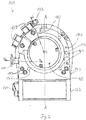
- turbomolecular pump 111 comprises a pump inlet 115 surrounded by an inlet flange 113, to which in a conventional manner, a non-illustrated recipient can be connected.
- the gas from the recipient may be drawn from the recipient via the pump inlet 115 and conveyed through the pump to a pump outlet 117 to which a backing pump, such as a rotary vane pump, may be connected.
- the inlet flange 113 forms according to the orientation of the vacuum pump Fig. 1 the upper end of the housing 119 of the vacuum pump 111.
- the housing 119 comprises a lower part 121, on which an electronics housing 123 is arranged laterally.
- Housed in the electronics housing 123 are electrical and / or electronic components of the vacuum pump 111, eg for operating an electric motor 125 arranged in the vacuum pump.
- a plurality of connections 127 for accessories are provided on the electronics housing 123.
- a data interface 129 for example, according to the RS485 standard, and a power supply terminal 131 on the electronics housing 123 are arranged.
- a flood inlet 133 On the housing 119 of the turbomolecular pump 111, a flood inlet 133, in particular in the form of a flood valve, is provided, via which the vacuum pump 111 can be flooded.
- a sealing gas connection 135, which is also referred to as flushing gas connection is arranged, via which flushing gas for protecting the electric motor 125 from the gas conveyed by the pump into the engine compartment 137, in which the electric motor 125 in the vacuum pump 111 housed, can be brought.
- two coolant connections 139 are further arranged, wherein one of the coolant connections is provided as an inlet and the other coolant connection as an outlet for coolant, which can be passed for cooling purposes in the vacuum pump.
- the lower side 141 of the vacuum pump can serve as a base, so that the vacuum pump 111 can be operated standing on the bottom 141.
- the vacuum pump 111 can also be fastened to a recipient via the inlet flange 113 and thus be operated to a certain extent suspended.
- the vacuum pump 111 can be designed so that it can also be put into operation, if it is aligned differently than in Fig. 1 is shown.
- Embodiments of the vacuum pump can also be implemented in which the lower side 141 can not be turned down but can be turned to the side or directed upwards.
- a bearing cap 145 is attached to the bottom 141.
- mounting holes 147 are arranged, via which the pump 111 can be attached, for example, to a support surface.
- a coolant line 148 is shown, in which the coolant introduced and discharged via the coolant connections 139 can circulate.
- the vacuum pump comprises a plurality of process gas pumping stages for conveying the process gas pending at the pump inlet 115 to the pump outlet 117.
- a rotor 149 is arranged, which has a about a rotation axis 151 rotatable rotor shaft 153.
- Turbomolecular pump 111 includes a plurality of turbomolecular pump stages operatively connected in series with a plurality of rotor disks 155 mounted on rotor shaft 153 and stator disks 157 disposed between rotor disks 155 and housed in housing 119.
- a rotor disk 155 and an adjacent stator disk 157 each form a turbomolecular one pump stage.
- the stator disks 157 are held by spacer rings 159 at a desired axial distance from each other.
- the vacuum pump further comprises Holweck pumping stages which are arranged one inside the other in the radial direction and which are pumpingly connected to one another in series.
- the rotor of the Holweck pump stages comprises a rotor hub 161 arranged on the rotor shaft 153 and two cylinder shell-shaped Holweck rotor sleeves 163, 165 fastened to the rotor hub 161 and oriented coaxially with the rotation axis 151 and nested in the radial direction.
- two cylinder jacket-shaped Holweck stator sleeves 167, 169 are provided, which are also oriented coaxially to the rotation axis 151 and, as seen in the radial direction, are nested one inside the other.
- the pump-active surfaces of the Holweck pump stages are formed by the lateral surfaces, ie by the radial inner and / or outer surfaces, the Holweck rotor sleeves 163, 165 and the Holweck stator sleeves 167, 169.
- the radially inner surface of the outer Holweck stator sleeve 167 faces the radially outer surface of the outer Holweck rotor sleeve 163, forming a radial Holweck gap 171, and forms with it the first Holweck pump stage subsequent to the turbomolecular pumps.
- the radially inner surface of the outer Holweck rotor sleeve 163 faces the radially outer surface of the inner Holweck stator sleeve 169 forming a radial Holweck gap 173 and forms with this a second Holweck pumping stage.
- the radially inner surface of the inner Holweck stator sleeve 169 faces the radially outer surface of the inner Holweck rotor sleeve 165 to form a radial Holweck gap 175 and forms with this the third Holweck pumping stage.
- a radially extending channel may be provided, via which the radially outer Holweck gap 171 is connected to the middle Holweck gap 173.
- a radially extending channel may be provided, via which the middle Holweck gap 173 is connected to the radially inner Holweck gap 175.
- a connecting channel 179 to the outlet 117 may be provided at the lower end of the radially inner Holweck rotor sleeve 165.
- the above-mentioned pump-active surfaces of the Holweck stator sleeves 163, 165 each have a plurality of Holweck grooves running around the axis of rotation 151 in the axial direction, while the opposite lateral surfaces of the Holweck rotor sleeves 163, 165 are smooth and the gas for operating the Drive vacuum pump 111 in the Holweck grooves.
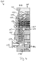
- a roller bearing 181 in the region of the pump outlet 117 and a permanent magnet bearing 183 in the region of the pump inlet 115 are provided for rotatably supporting the rotor shaft 153.
- a conical spray nut 185 with an outer diameter increasing toward the rolling bearing 181 is provided on the rotor shaft 153.
- the spray nut 185 is in sliding contact with at least one scraper of a resource storage.
- the resource storage comprises a plurality of stackable absorbent discs 187 provided with a rolling bearing bearing means 181, e.g. with a lubricant, soaked.
- the operating means is transferred by capillary action of the resource storage on the scraper on the rotating sprayer nut 185 and due to the centrifugal force along the spray nut 185 in the direction of increasing outer diameter of the injection nut 92 to the roller bearing 181 out promoted, where eg fulfills a lubricating function.
- the rolling bearing 181 and the resource storage are enclosed by a trough-shaped insert 189 and the bearing cap 145 in the vacuum pump.
- the permanent magnet bearing 183 includes a rotor-side bearing half 191 and a stator-side bearing half 193, each comprising a ring stack of a plurality of stacked in the axial direction of permanent magnetic rings 195, 197 include.
- the ring magnets 195, 197 are opposed to each other to form a radial bearing gap 199, wherein the rotor-side ring magnets 195 are disposed radially outward and the stator-side ring magnets 197 radially inward.
- the magnetic field present in the bearing gap 199 causes magnetic repulsive forces between the ring magnets 195, 197, which cause a radial bearing of the rotor shaft 153.
- the rotor-side ring magnets 195 are supported by a carrier section 201 of the rotor shaft 153, which surrounds the ring magnets 195 radially on the outside.
- the stator-side ring magnets 197 are supported by a stator-side support portion 203 which extends through the ring magnets 197 and is suspended on radial struts 205 of the housing 119.
- Parallel to the axis of rotation 151, the rotor-side ring magnets 195 are fixed by a lid element 207 coupled to the carrier section 203.
- the stator-side ring magnets 197 are fixed parallel to the axis of rotation 151 in one direction by a fastening ring 209 connected to the carrier section 203 and a fastening ring 211 connected to the carrier section 203. Between the fastening ring 211 and the ring magnet 197, a plate spring 213 may also be provided.
- an emergency or catch bearing 215 which runs empty during normal operation of the vacuum pump 111 without contact and only with an excessive radial deflection of the rotor 149 relative to the stator engages to a radial stop for the rotor 149 to form, since a collision of the rotor-side structures is prevented with the stator-side structures.
- the safety bearing 215 is designed as an unlubricated rolling bearing and forms with the rotor 149 and / or the stator a radial gap, which causes the safety bearing 215 is disengaged in the normal pumping operation.
- the radial deflection at which the safety bearing 215 engages is dimensioned large enough so that the safety bearing 215 does not engage during normal operation of the vacuum pump, and at the same time small enough so that a collision of the rotor-side structures with the stator-side structures under all circumstances is prevented.
- the vacuum pump 111 includes the electric motor 125 for rotationally driving the rotor 149.
- the armature of the electric motor 125 is formed by the rotor 149 whose rotor shaft 153 extends through the motor stator 217.
- On the extending through the motor stator 217 through portion of the rotor shaft 153 may radially outside or embedded a permanent magnet assembly be arranged.
- a gap 219 is arranged, which comprises a radial motor gap, via which the motor stator 217 and the permanent magnet arrangement for the transmission of the drive torque can influence magnetically.
- the motor stator 217 is fixed in the housing within the motor space 137 provided for the electric motor 125.
- a sealing gas which is also referred to as purge gas, and which may be, for example, air or nitrogen, enter the engine compartment 137.
- the electric motor 125 can be provided with process gas, e.g. against corrosive fractions of the process gas.
- the engine compartment 137 may also be evacuated via the pump outlet 117, i. In the engine compartment 137, at least approximately, the vacuum pressure caused by the backing pump connected to the pump outlet 117 prevails.
- delimiting wall 221 Between the rotor hub 161 and a motor space 137 delimiting wall 221 may also be a so-called. And per se known labyrinth seal 223 may be provided, in particular to achieve a better seal of the engine compartment 217 against the Holweck pump stages located radially outside.
- the turbomolecular pump of Fig. 1 to 5 forms a vacuum pump according to the invention.
- the Fig. 6 shows details which also in a turbomolecular pump according to the Fig. 1 to 5 may be provided, even if they are not explicitly shown there.
- FIG. 12 shows a schematic block diagram of a turbomolecular pump 111 according to an embodiment of the present invention.
- the in the Fig. 6 shown turbomolecular pump 111 has a plurality of pump components 225, a heater 227 for heating at least one of the pump components 225 and a sensor 229 for detecting a measured variable for the pump operation.
- a plurality of sensors 229 for example, a sensor 229 per pump component 225th
- the sensor 229 according to the invention is arranged independently of the heater 227.
- the sensor 229 is not arranged as part of the heater 227 or within the heater 227 but spaced therefrom.
- the sensor 227 can be arranged, for example, in a pump interior, in particular in or on a pump component 225, and thus configured to detect a measured variable directly in or on the pump component 225.
- the respective measured variable can be detected in critical regions or adjacent critical regions of the turbomolecular pump 111.
- the sensor 229 may be designed to detect a measured variable for the control and / or regulation of the pump operation, in particular a pump drive 231.
- the pump drive 231 may correspond to or have the electric motor 125 described above.
- the sensor 229 can also be designed to influence the pump operation, in particular the pump drive 231, via a pump control and / or pump control device 233.
- the sensor 229 may be in communication with the pump control and / or pump control device 233, in particular via a wired or wireless data connection.
- the sensor 229 may be designed in particular as a temperature sensor. Accordingly, the sensor 229 may be configured to detect a pump operating temperature and / or to detect the temperature of the pump component 225, in particular to detect a predefined maximum temperature of the pump component 225.
- the heating device 227 is configured for operation as a function of the measured variable detected by the sensor 225, in particular a detected temperature.
- the heating operation of the heating device 227 accordingly takes place as a function of sensor data, in particular temperature data, which are detected by the sensor 229.
- the heater 227 may thus be formed without own sensors, whereby the number of components can be reduced.
- the sensor 229 may be connected directly to the heating device 227, in particular via a data connection.
- the sensor 229 may be indirectly connected to the heater 227 via the pump control and / or pump control means 233.
- the latter applies in particular in the case of the control and / or regulation of the heater 227 via the pump control and / or pump control device 233.
- the data connections can be wired or wireless.
- the heater 227 may be configured to maintain a minimum temperature and / or maximum temperature and / or to heat up to a minimum temperature and / or maximum temperature. This may be a temperature detected by the sensor 229 on the pump component 225, wherein the respective minimum temperature or maximum temperature may be predefined, in particular with regard to the desired operating properties of the turbomolecular pump 111 and / or with regard to material and wear properties of the respective ones Pump component 225.
- the minimum temperature with regard to low tendency to condensation and the maximum temperature can be selected in terms of allowable material stress.
- the heater 227 may further be configured to be activated when falling below a predefined limit temperature and / or deactivated when the predefined limit temperature is exceeded. Further, the heating power of the heater 227 can be adjusted and / or compensated for falling below or exceeding the limit temperature.
- the predefined limit temperature may be a maximum or minimum temperature.
- the heater 227 may thus be configured to be fully powered-up in pump mode. Likewise, a control of the heater 227 can be effected by means of pulsed, linearly variable or by means of discrete intermediate values.
- the turbomolecular pump 111 has a pump drive 231.
- the heating device 227 may be configured for operation as a function of a power absorbed by the pump drive 231.
- the heater 227 may be configured to increase the power consumption of the pump drive 231 to maintain a deactivated state and / or to reduce the heating power.
- the heater 227 may be configured to reduce the power consumption of the pump drive 231 to activate the heating operation and / or increase the heating power. Furthermore, the heater 227 may be configured to remain deactivated in a pump start-up operation and / or in a vacuum-generating operation and / or to be activated in a vacuum-maintaining operation. Activation and / or deactivation and / or variation of the heating power may be performed by the pump control and / or pump control means 233 or by a dedicated unit provided in the heater 227, respectively.
- the pump drive 231 has a power supply unit 235.
- the power supply unit 235 can - unlike in Fig. 6 represented - also be arranged outside the pump drive 231 and connected to this.
- the power source heater 227 is set up by the power supply unit 235 of the pump driver 231. The heater 227 thus does not require its own power supply unit, so that the component number of the turbomolecular pump 111 can be further reduced.
- Other components and / or devices of the vacuum pump may be configured to draw power from the power supply unit 235 of the pump drive 231, such as the pump control and / or pump control means 233.
- all consumers of the turbomolecular pump 111 for power supply from the power supply unit 235 of the pump drive 231 be furnished.
- the available power of the power supply unit 235 may be divided at least between the pump drive 231 and the heater 227. In a particularly advantageous manner, the available power of the power supply unit 235 can be completely divided between the respective connected consumers.
- available 100 watts from a power supply unit 235 configured as a power supply may be substantially split between the pump drive 231 and the heater 227.
- the division can be made depending on the operating state. For example, 90 watts may be needed by pump drive 231 in a pump start-up operation.
- the heater 227 remains deactivated. In a vacuum-generating operation, for example, a vacuum chamber is pumped empty, so that a relatively high gas load is present.
- the pump drive 231 may require, for example, 50 watts here.
- the heater 227 continues to be deactivated or activated and operated at a low power of about 50 watts or less.
- a vacuum chamber In a vacuum-maintaining operation, a vacuum chamber is already pumped empty, so that there is a relatively low or no gas load.
- the turbomolecular pump 111 is thus operated at an operating point without or with only a small gas load, so that the pump drive 231, for example, requires 20 watts or less.
- the heater 227 may be operated at 80 watts in this state to prevent over-cooling of the pump component 225.
Landscapes
- Engineering & Computer Science (AREA)
- Mechanical Engineering (AREA)
- General Engineering & Computer Science (AREA)
- Physics & Mathematics (AREA)
- Thermal Sciences (AREA)
- Non-Positive Displacement Air Blowers (AREA)
Priority Applications (2)
| Application Number | Priority Date | Filing Date | Title |
|---|---|---|---|
| EP18167557.0A EP3557071B1 (fr) | 2018-04-16 | 2018-04-16 | Pompe à vide et procédé de fonctionnement d'une telle pompe à vide |
| JP2019041548A JP2019183831A (ja) | 2018-04-16 | 2019-03-07 | 真空ポンプおよびこれを作動させるための方法 |
Applications Claiming Priority (1)
| Application Number | Priority Date | Filing Date | Title |
|---|---|---|---|
| EP18167557.0A EP3557071B1 (fr) | 2018-04-16 | 2018-04-16 | Pompe à vide et procédé de fonctionnement d'une telle pompe à vide |
Publications (2)
| Publication Number | Publication Date |
|---|---|
| EP3557071A1 true EP3557071A1 (fr) | 2019-10-23 |
| EP3557071B1 EP3557071B1 (fr) | 2021-09-22 |
Family
ID=62002562
Family Applications (1)
| Application Number | Title | Priority Date | Filing Date |
|---|---|---|---|
| EP18167557.0A Active EP3557071B1 (fr) | 2018-04-16 | 2018-04-16 | Pompe à vide et procédé de fonctionnement d'une telle pompe à vide |
Country Status (2)
| Country | Link |
|---|---|
| EP (1) | EP3557071B1 (fr) |
| JP (1) | JP2019183831A (fr) |
Citations (3)
| Publication number | Priority date | Publication date | Assignee | Title |
|---|---|---|---|---|
| EP1178217A2 (fr) * | 2000-07-31 | 2002-02-06 | Seiko Instruments Inc. | Pompe à vide |
| JP2013079602A (ja) * | 2011-10-04 | 2013-05-02 | Shimadzu Corp | ターボ分子ポンプ |
| US20150275914A1 (en) * | 2014-03-28 | 2015-10-01 | Shimadzu Corporation | Vacuum pump |
Family Cites Families (3)
| Publication number | Priority date | Publication date | Assignee | Title |
|---|---|---|---|---|
| JP3557608B2 (ja) * | 1996-05-30 | 2004-08-25 | 株式会社島津製作所 | ターボ分子ポンプの電源装置 |
| JP2003172292A (ja) * | 2001-12-04 | 2003-06-20 | Shimadzu Corp | ターボ分子ポンプ駆動用電源装置 |
| WO2011021428A1 (fr) * | 2009-08-21 | 2011-02-24 | エドワーズ株式会社 | Pompe à vide |
-
2018
- 2018-04-16 EP EP18167557.0A patent/EP3557071B1/fr active Active
-
2019
- 2019-03-07 JP JP2019041548A patent/JP2019183831A/ja active Pending
Patent Citations (3)
| Publication number | Priority date | Publication date | Assignee | Title |
|---|---|---|---|---|
| EP1178217A2 (fr) * | 2000-07-31 | 2002-02-06 | Seiko Instruments Inc. | Pompe à vide |
| JP2013079602A (ja) * | 2011-10-04 | 2013-05-02 | Shimadzu Corp | ターボ分子ポンプ |
| US20150275914A1 (en) * | 2014-03-28 | 2015-10-01 | Shimadzu Corporation | Vacuum pump |
Non-Patent Citations (1)
| Title |
|---|
| DATABASE WPI Week 201330, Derwent World Patents Index; AN 2013-G54479, XP002784555 * |
Also Published As
| Publication number | Publication date |
|---|---|
| EP3557071B1 (fr) | 2021-09-22 |
| JP2019183831A (ja) | 2019-10-24 |
Similar Documents
| Publication | Publication Date | Title |
|---|---|---|
| EP2826999B1 (fr) | Pompe à vide | |
| EP3657021B1 (fr) | Pompe à vide | |
| EP3653885B1 (fr) | Procédé de détermination d'une information d'état dans un appareil sous vide | |
| EP4108932B1 (fr) | Reciate et système avec reciate et pompe à vide élevé | |
| EP3438460B1 (fr) | Pompe à vide | |
| EP3112687B1 (fr) | Détection de la circulation d'un gaz auxiliaire qui est injecté dans une pompe à vide | |
| EP3657022A1 (fr) | Pompe à vide, procédé de mise en température pour une pompe a vide | |
| EP3660317B1 (fr) | Appareil à vide | |
| EP3557071B1 (fr) | Pompe à vide et procédé de fonctionnement d'une telle pompe à vide | |
| EP3557072B1 (fr) | Surveillance d'un dispositif de palier d'une pompe à vide | |
| EP3473858B1 (fr) | Procédé d'optimisation de durée de vie des paliers à rouleaux d'une pompe à vide | |
| EP4194700B1 (fr) | Pompe à vide avec étage de pompe de holweck à géométrie de holweck variable | |
| EP3683449A1 (fr) | Palier magnétique et appareil sous vide | |
| EP3327293B1 (fr) | Pompe à vide avec une pluralté d'entrées | |
| EP3907406B1 (fr) | Pompe à vide | |
| EP4212730A1 (fr) | Pompe à vide avec étage de pompage de holward optimisé pour compenser la perte de performance liée à la température | |
| EP3683447A1 (fr) | Pompe à vide | |
| EP3135932A1 (fr) | Pompe a vide et palier a aimant permanent | |
| EP3628873B1 (fr) | Logement de rotor | |
| EP3611383B1 (fr) | Réglage de vitesse de rotation d'un rotor d'une pompe à vide | |
| EP3633204B1 (fr) | Pompe à vide | |
| EP3650702B1 (fr) | Utilisation d'une huile synthétique dans une pompe à vide et pompe à vide | |
| EP4174321B1 (fr) | Pompe à vide | |
| EP3536966B1 (fr) | Appareil à vide | |
| EP3926174B1 (fr) | Pompe à vide |
Legal Events
| Date | Code | Title | Description |
|---|---|---|---|
| PUAI | Public reference made under article 153(3) epc to a published international application that has entered the european phase |
Free format text: ORIGINAL CODE: 0009012 |
|
| STAA | Information on the status of an ep patent application or granted ep patent |
Free format text: STATUS: THE APPLICATION HAS BEEN PUBLISHED |
|
| AK | Designated contracting states |
Kind code of ref document: A1 Designated state(s): AL AT BE BG CH CY CZ DE DK EE ES FI FR GB GR HR HU IE IS IT LI LT LU LV MC MK MT NL NO PL PT RO RS SE SI SK SM TR |
|
| AX | Request for extension of the european patent |
Extension state: BA ME |
|
| STAA | Information on the status of an ep patent application or granted ep patent |
Free format text: STATUS: REQUEST FOR EXAMINATION WAS MADE |
|
| 17P | Request for examination filed |
Effective date: 20200416 |
|
| RBV | Designated contracting states (corrected) |
Designated state(s): AL AT BE BG CH CY CZ DE DK EE ES FI FR GB GR HR HU IE IS IT LI LT LU LV MC MK MT NL NO PL PT RO RS SE SI SK SM TR |
|
| STAA | Information on the status of an ep patent application or granted ep patent |
Free format text: STATUS: EXAMINATION IS IN PROGRESS |
|
| 17Q | First examination report despatched |
Effective date: 20201005 |
|
| GRAP | Despatch of communication of intention to grant a patent |
Free format text: ORIGINAL CODE: EPIDOSNIGR1 |
|
| STAA | Information on the status of an ep patent application or granted ep patent |
Free format text: STATUS: GRANT OF PATENT IS INTENDED |
|
| INTG | Intention to grant announced |
Effective date: 20210429 |
|
| GRAS | Grant fee paid |
Free format text: ORIGINAL CODE: EPIDOSNIGR3 |
|
| GRAA | (expected) grant |
Free format text: ORIGINAL CODE: 0009210 |
|
| STAA | Information on the status of an ep patent application or granted ep patent |
Free format text: STATUS: THE PATENT HAS BEEN GRANTED |
|
| AK | Designated contracting states |
Kind code of ref document: B1 Designated state(s): AL AT BE BG CH CY CZ DE DK EE ES FI FR GB GR HR HU IE IS IT LI LT LU LV MC MK MT NL NO PL PT RO RS SE SI SK SM TR |
|
| REG | Reference to a national code |
Ref country code: GB Ref legal event code: FG4D Free format text: NOT ENGLISH |
|
| REG | Reference to a national code |
Ref country code: DE Ref legal event code: R096 Ref document number: 502018007136 Country of ref document: DE |
|
| REG | Reference to a national code |
Ref country code: IE Ref legal event code: FG4D Free format text: LANGUAGE OF EP DOCUMENT: GERMAN |
|
| REG | Reference to a national code |
Ref country code: CH Ref legal event code: EP Ref country code: AT Ref legal event code: REF Ref document number: 1432542 Country of ref document: AT Kind code of ref document: T Effective date: 20211015 |
|
| REG | Reference to a national code |
Ref country code: LT Ref legal event code: MG9D |
|
| REG | Reference to a national code |
Ref country code: NL Ref legal event code: MP Effective date: 20210922 |
|
| PG25 | Lapsed in a contracting state [announced via postgrant information from national office to epo] |
Ref country code: RS Free format text: LAPSE BECAUSE OF FAILURE TO SUBMIT A TRANSLATION OF THE DESCRIPTION OR TO PAY THE FEE WITHIN THE PRESCRIBED TIME-LIMIT Effective date: 20210922 Ref country code: SE Free format text: LAPSE BECAUSE OF FAILURE TO SUBMIT A TRANSLATION OF THE DESCRIPTION OR TO PAY THE FEE WITHIN THE PRESCRIBED TIME-LIMIT Effective date: 20210922 Ref country code: HR Free format text: LAPSE BECAUSE OF FAILURE TO SUBMIT A TRANSLATION OF THE DESCRIPTION OR TO PAY THE FEE WITHIN THE PRESCRIBED TIME-LIMIT Effective date: 20210922 Ref country code: FI Free format text: LAPSE BECAUSE OF FAILURE TO SUBMIT A TRANSLATION OF THE DESCRIPTION OR TO PAY THE FEE WITHIN THE PRESCRIBED TIME-LIMIT Effective date: 20210922 Ref country code: NO Free format text: LAPSE BECAUSE OF FAILURE TO SUBMIT A TRANSLATION OF THE DESCRIPTION OR TO PAY THE FEE WITHIN THE PRESCRIBED TIME-LIMIT Effective date: 20211222 Ref country code: BG Free format text: LAPSE BECAUSE OF FAILURE TO SUBMIT A TRANSLATION OF THE DESCRIPTION OR TO PAY THE FEE WITHIN THE PRESCRIBED TIME-LIMIT Effective date: 20211222 Ref country code: LT Free format text: LAPSE BECAUSE OF FAILURE TO SUBMIT A TRANSLATION OF THE DESCRIPTION OR TO PAY THE FEE WITHIN THE PRESCRIBED TIME-LIMIT Effective date: 20210922 |
|
| PG25 | Lapsed in a contracting state [announced via postgrant information from national office to epo] |
Ref country code: LV Free format text: LAPSE BECAUSE OF FAILURE TO SUBMIT A TRANSLATION OF THE DESCRIPTION OR TO PAY THE FEE WITHIN THE PRESCRIBED TIME-LIMIT Effective date: 20210922 Ref country code: GR Free format text: LAPSE BECAUSE OF FAILURE TO SUBMIT A TRANSLATION OF THE DESCRIPTION OR TO PAY THE FEE WITHIN THE PRESCRIBED TIME-LIMIT Effective date: 20211223 |
|
| PG25 | Lapsed in a contracting state [announced via postgrant information from national office to epo] |
Ref country code: IS Free format text: LAPSE BECAUSE OF FAILURE TO SUBMIT A TRANSLATION OF THE DESCRIPTION OR TO PAY THE FEE WITHIN THE PRESCRIBED TIME-LIMIT Effective date: 20220122 Ref country code: SK Free format text: LAPSE BECAUSE OF FAILURE TO SUBMIT A TRANSLATION OF THE DESCRIPTION OR TO PAY THE FEE WITHIN THE PRESCRIBED TIME-LIMIT Effective date: 20210922 Ref country code: RO Free format text: LAPSE BECAUSE OF FAILURE TO SUBMIT A TRANSLATION OF THE DESCRIPTION OR TO PAY THE FEE WITHIN THE PRESCRIBED TIME-LIMIT Effective date: 20210922 Ref country code: PT Free format text: LAPSE BECAUSE OF FAILURE TO SUBMIT A TRANSLATION OF THE DESCRIPTION OR TO PAY THE FEE WITHIN THE PRESCRIBED TIME-LIMIT Effective date: 20220124 Ref country code: PL Free format text: LAPSE BECAUSE OF FAILURE TO SUBMIT A TRANSLATION OF THE DESCRIPTION OR TO PAY THE FEE WITHIN THE PRESCRIBED TIME-LIMIT Effective date: 20210922 Ref country code: NL Free format text: LAPSE BECAUSE OF FAILURE TO SUBMIT A TRANSLATION OF THE DESCRIPTION OR TO PAY THE FEE WITHIN THE PRESCRIBED TIME-LIMIT Effective date: 20210922 Ref country code: ES Free format text: LAPSE BECAUSE OF FAILURE TO SUBMIT A TRANSLATION OF THE DESCRIPTION OR TO PAY THE FEE WITHIN THE PRESCRIBED TIME-LIMIT Effective date: 20210922 Ref country code: EE Free format text: LAPSE BECAUSE OF FAILURE TO SUBMIT A TRANSLATION OF THE DESCRIPTION OR TO PAY THE FEE WITHIN THE PRESCRIBED TIME-LIMIT Effective date: 20210922 Ref country code: AL Free format text: LAPSE BECAUSE OF FAILURE TO SUBMIT A TRANSLATION OF THE DESCRIPTION OR TO PAY THE FEE WITHIN THE PRESCRIBED TIME-LIMIT Effective date: 20210922 |
|
| REG | Reference to a national code |
Ref country code: DE Ref legal event code: R097 Ref document number: 502018007136 Country of ref document: DE |
|
| PG25 | Lapsed in a contracting state [announced via postgrant information from national office to epo] |
Ref country code: DK Free format text: LAPSE BECAUSE OF FAILURE TO SUBMIT A TRANSLATION OF THE DESCRIPTION OR TO PAY THE FEE WITHIN THE PRESCRIBED TIME-LIMIT Effective date: 20210922 |
|
| PLBE | No opposition filed within time limit |
Free format text: ORIGINAL CODE: 0009261 |
|
| STAA | Information on the status of an ep patent application or granted ep patent |
Free format text: STATUS: NO OPPOSITION FILED WITHIN TIME LIMIT |
|
| 26N | No opposition filed |
Effective date: 20220623 |
|
| PG25 | Lapsed in a contracting state [announced via postgrant information from national office to epo] |
Ref country code: SI Free format text: LAPSE BECAUSE OF FAILURE TO SUBMIT A TRANSLATION OF THE DESCRIPTION OR TO PAY THE FEE WITHIN THE PRESCRIBED TIME-LIMIT Effective date: 20210922 |
|
| REG | Reference to a national code |
Ref country code: CH Ref legal event code: PL |
|
| REG | Reference to a national code |
Ref country code: BE Ref legal event code: MM Effective date: 20220430 |
|
| PG25 | Lapsed in a contracting state [announced via postgrant information from national office to epo] |
Ref country code: MC Free format text: LAPSE BECAUSE OF FAILURE TO SUBMIT A TRANSLATION OF THE DESCRIPTION OR TO PAY THE FEE WITHIN THE PRESCRIBED TIME-LIMIT Effective date: 20210922 Ref country code: LU Free format text: LAPSE BECAUSE OF NON-PAYMENT OF DUE FEES Effective date: 20220416 Ref country code: LI Free format text: LAPSE BECAUSE OF NON-PAYMENT OF DUE FEES Effective date: 20220430 Ref country code: FR Free format text: LAPSE BECAUSE OF NON-PAYMENT OF DUE FEES Effective date: 20220430 Ref country code: CH Free format text: LAPSE BECAUSE OF NON-PAYMENT OF DUE FEES Effective date: 20220430 |
|
| PG25 | Lapsed in a contracting state [announced via postgrant information from national office to epo] |
Ref country code: BE Free format text: LAPSE BECAUSE OF NON-PAYMENT OF DUE FEES Effective date: 20220430 |
|
| PG25 | Lapsed in a contracting state [announced via postgrant information from national office to epo] |
Ref country code: IE Free format text: LAPSE BECAUSE OF NON-PAYMENT OF DUE FEES Effective date: 20220416 |
|
| PG25 | Lapsed in a contracting state [announced via postgrant information from national office to epo] |
Ref country code: HU Free format text: LAPSE BECAUSE OF FAILURE TO SUBMIT A TRANSLATION OF THE DESCRIPTION OR TO PAY THE FEE WITHIN THE PRESCRIBED TIME-LIMIT; INVALID AB INITIO Effective date: 20180416 |
|
| PG25 | Lapsed in a contracting state [announced via postgrant information from national office to epo] |
Ref country code: SM Free format text: LAPSE BECAUSE OF FAILURE TO SUBMIT A TRANSLATION OF THE DESCRIPTION OR TO PAY THE FEE WITHIN THE PRESCRIBED TIME-LIMIT Effective date: 20210922 Ref country code: MK Free format text: LAPSE BECAUSE OF FAILURE TO SUBMIT A TRANSLATION OF THE DESCRIPTION OR TO PAY THE FEE WITHIN THE PRESCRIBED TIME-LIMIT Effective date: 20210922 Ref country code: CY Free format text: LAPSE BECAUSE OF FAILURE TO SUBMIT A TRANSLATION OF THE DESCRIPTION OR TO PAY THE FEE WITHIN THE PRESCRIBED TIME-LIMIT Effective date: 20210922 |
|
| REG | Reference to a national code |
Ref country code: AT Ref legal event code: MM01 Ref document number: 1432542 Country of ref document: AT Kind code of ref document: T Effective date: 20230416 |
|
| PG25 | Lapsed in a contracting state [announced via postgrant information from national office to epo] |
Ref country code: TR Free format text: LAPSE BECAUSE OF FAILURE TO SUBMIT A TRANSLATION OF THE DESCRIPTION OR TO PAY THE FEE WITHIN THE PRESCRIBED TIME-LIMIT Effective date: 20210922 |
|
| PG25 | Lapsed in a contracting state [announced via postgrant information from national office to epo] |
Ref country code: AT Free format text: LAPSE BECAUSE OF NON-PAYMENT OF DUE FEES Effective date: 20230416 |
|
| PG25 | Lapsed in a contracting state [announced via postgrant information from national office to epo] |
Ref country code: AT Free format text: LAPSE BECAUSE OF NON-PAYMENT OF DUE FEES Effective date: 20230416 |
|
| PG25 | Lapsed in a contracting state [announced via postgrant information from national office to epo] |
Ref country code: MT Free format text: LAPSE BECAUSE OF FAILURE TO SUBMIT A TRANSLATION OF THE DESCRIPTION OR TO PAY THE FEE WITHIN THE PRESCRIBED TIME-LIMIT Effective date: 20210922 |
|
| PGFP | Annual fee paid to national office [announced via postgrant information from national office to epo] |
Ref country code: DE Payment date: 20250625 Year of fee payment: 8 |
|
| PGFP | Annual fee paid to national office [announced via postgrant information from national office to epo] |
Ref country code: GB Payment date: 20250423 Year of fee payment: 8 |
|
| PGFP | Annual fee paid to national office [announced via postgrant information from national office to epo] |
Ref country code: IT Payment date: 20250424 Year of fee payment: 8 |
|
| PGFP | Annual fee paid to national office [announced via postgrant information from national office to epo] |
Ref country code: CZ Payment date: 20250407 Year of fee payment: 8 |
|
| PGFP | Annual fee paid to national office [announced via postgrant information from national office to epo] |
Ref country code: AT Payment date: 20260410 Year of fee payment: 5 |