EP3556944B1 - Schachtabdeckungsrahmen, schachtabdeckungsanordnung, schachtanordnung und installationsverfahren - Google Patents
Schachtabdeckungsrahmen, schachtabdeckungsanordnung, schachtanordnung und installationsverfahren Download PDFInfo
- Publication number
- EP3556944B1 EP3556944B1 EP19164383.2A EP19164383A EP3556944B1 EP 3556944 B1 EP3556944 B1 EP 3556944B1 EP 19164383 A EP19164383 A EP 19164383A EP 3556944 B1 EP3556944 B1 EP 3556944B1
- Authority
- EP
- European Patent Office
- Prior art keywords
- frame
- shaft
- predetermined breaking
- apron
- breaking point
- Prior art date
- Legal status (The legal status is an assumption and is not a legal conclusion. Google has not performed a legal analysis and makes no representation as to the accuracy of the status listed.)
- Active
Links
Images


Classifications
-
- E—FIXED CONSTRUCTIONS
- E02—HYDRAULIC ENGINEERING; FOUNDATIONS; SOIL SHIFTING
- E02D—FOUNDATIONS; EXCAVATIONS; EMBANKMENTS; UNDERGROUND OR UNDERWATER STRUCTURES
- E02D29/00—Independent underground or underwater structures; Retaining walls
- E02D29/12—Manhole shafts; Other inspection or access chambers; Accessories therefor
- E02D29/121—Manhole shafts; Other inspection or access chambers; Accessories therefor characterised by the connection between shaft elements, e.g. of rings forming said shaft
Definitions
- the invention relates to a manhole cover frame according to the preamble of claim 1, a manhole cover arrangement herewith according to claim 10, a manhole arrangement with such a manhole cover arrangement according to claim 11 and a method for installing the manhole cover frame according to claim 12.
- Manhole cover arrangements are used to cover manholes and usually have a manhole cover frame and a closure element with which a passage opening in the manhole cover frame can be closed.
- Such manhole cover frames are installed in particular at the upper end of a manhole structure.
- a floor-level installation of the manhole cover frame and the closure element in the traffic area is necessary.
- the problem with the current state of the art is that the distance between the shaft structure and the traffic area is variable. If the building contractor knows about this in advance, distance, he can order a manhole cover arrangement that is a suitable length. Even with advance planning, but especially during renovations, it often turns out on the construction site that the height of the manhole cover arrangement brought with it is too great and would protrude beyond the traffic area if installed. In practice, construction work is then interrupted until a shorter manhole cover arrangement arrives. This results in additional costs due to repeated trips, ordering processes and securing the construction site. In addition, traffic on the traffic area is impeded for a longer period of time.
- a manhole cover frame for a manhole cover arrangement for use in new road construction and in rehabilitation processes. This has a frame apron through which a manhole passage runs. The manhole cover frame also has a locking element holder.
- EP 2 317 197 A1 indicates a dimensionally stable water pipe that has a sleeve with a metal layer and a plastic layer. This sleeve has predetermined breaking points for cutting to length.
- EN 10 2006 056 146 A1 specifies an installation body for floor slabs of buildings, which forms a service opening to a pipeline under the floor slab, as described by way of example to a backflow flap.
- This installation body has a vertically aligned passage into which an elongated, rectangular attachment element with a connection piece is inserted.
- This attachment element is cast into the floor slab with the connection piece (together with the installation body) in such a way that its upper side is flush with the surface of the floor slab.
- the insertion section Due to different thicknesses of the floor slabs and distances of the pipeline lying under the floor line, the insertion section is designed to be shortened.
- the connection piece has cutting markings at which the piece can be cut according to EN 10 2006 056 146 A1 can be sawn off.
- the connection piece according to EN 10 2006 056 146 A1 there is a single cutting mark designed as a predetermined breaking point.
- the object of the invention is to provide a manhole cover arrangement, individual parts thereof or method instructions with which the aforementioned disadvantages are overcome so that the installation of the manhole cover arrangement can be continued without having to interrupt the construction site activity.
- the invention relates to a manhole cover frame for a manhole cover arrangement for use in new road construction and in renovation processes, which forms a manhole passage running in a longitudinal direction, with a closure element receptacle, in particular for receiving a closure element of a manhole cover arrangement with which the manhole passage can be closed, and with a frame apron with an inner side, an outer side and a length in the longitudinal direction, wherein the manhole passage runs through the frame apron, wherein the frame apron has a first predetermined breaking point that runs transversely to the longitudinal direction, and the frame apron is divided into a first section that borders the closure element receptacle and a second section that can be broken off specifically along the first predetermined breaking point, namely in such a way that the length of the frame apron can be shortened, in particular irreversibly by breaking or breaking off, wherein the first predetermined breaking point runs along the circumference of the frame apron.
- the manhole cover frame is made of cast iron and the first predetermined breaking point is designed as a predetermined breaking groove at least in sections, wherein the frame apron has a wall thickness and the predetermined breaking groove has a groove depth which is at least 25% of the wall thickness of the frame apron in the region of the predetermined breaking groove.
- the building contractor now has the option of using this manhole cover frame according to the invention to adjust the length of the manhole cover frame by shortening the frame apron in order to adapt it to the existing road structure without having to leave the construction site. Due to the predetermined breaking point, this can be achieved in particular with inexpensive and almost always available tools, e.g. a hammer, a spade or a pickaxe. The breaking off is also much faster, more precise and less dangerous than, for example, cutting off with a grinder.
- the targeted breaking off leads to an irreversible division of the entire component and is based on a targeted mechanical Initiation of crack formation in the area of the predetermined breaking point, whereby the first section of the manhole cover frame alone remains usable, in particular because this first section is not damaged.
- the first predetermined breaking point runs along the circumference of the frame apron, an even shortening of the frame apron over the circumference can be achieved.
- the first predetermined breaking point is designed as a predetermined breaking groove at least in sections, with the predetermined breaking groove preferably running along the entire circumference of the frame apron.
- a predetermined breaking groove contributes to a clean break-off edge and is easy to produce. This also prevents damage to the first section in particular. If it runs over the entire circumference, the break-off edge is also cleanly defined over the entire circumference.
- the predetermined breaking groove is arranged on the outside of the frame apron. On the one hand, this contributes to a smooth surface on the inside of the frame apron. On the other hand, a blow with a tool to trigger a predetermined breaking point on the outside can be carried out easily and precisely.
- the frame apron has a wall thickness and the predetermined breaking groove has a groove depth that is at least 25%, and preferably at least 30%, of the wall thickness of the frame apron in the area of the predetermined breaking groove.
- the frame apron is thus weakened in this area compared to the adjacent wall thickness of the frame apron to such an extent that the predetermined breaking point can be produced cleanly along the predetermined breaking groove.
- the groove depth is a maximum of 60%, and preferably a maximum of 50%, of the wall thickness of the frame apron in the area of the predetermined breaking groove.
- the second section is thus still comparatively stable connected to the first section of the frame apron and can bear traffic loads even when not shortened.
- the predetermined breaking groove has a rounded groove cross-section. Due to the lack of corners in the cross-sectional profile, larger traffic loads can be transferred between the first and second sections without spontaneous material fractures occurring at the predetermined breaking point. In addition, a minimum wall thickness is achieved in the area of the groove base along a tangent line along which the predetermined breaking point can be achieved.
- the frame apron has at least one second predetermined breaking point, which runs transversely to the longitudinal direction and divides the breakable second section of the frame apron into a a first section that can be broken off in a targeted manner and a further section that can be broken off in a targeted manner, in particular in such a way that the length of the frame apron can be shortened to two different values, in particular irreversibly by breaking or breaking off.
- the at least one second predetermined breaking point should be arranged between the first predetermined breaking point and an end of the frame apron facing away from the closure element holder.
- the second predetermined breaking point In a design with at least one such second predetermined breaking point, it is advantageous to dimension the second predetermined breaking point so that it is weaker than the first predetermined breaking point. This allows the predetermined breaking point to be achieved at the second predetermined breaking point with a low risk of triggering a predetermined breaking point at the first predetermined breaking point.
- the second predetermined breaking point can optionally have the individual optional features of the first predetermined breaking point.
- the second predetermined breaking point can optionally run along the circumference of the frame apron.
- the second predetermined breaking point can also be designed as a predetermined breaking groove, at least in sections. It is advantageous if the predetermined breaking groove of the second predetermined breaking point is arranged on the outside of the frame apron.
- the frame apron has a wall thickness and the predetermined breaking groove of the second predetermined breaking point has a groove depth that is at least 25%, and preferably at least 30%, of the wall thickness of the frame apron in the area of the predetermined breaking groove.
- the groove depth of the predetermined breaking groove of the second predetermined breaking point is a maximum of 60%, and preferably a maximum of 50%, of the wall thickness of the frame apron in the area of the predetermined breaking groove.
- the predetermined breaking groove of the second predetermined breaking point has a rounded groove cross-section.
- the breakable second section of the frame apron has at least one segmentation predetermined breaking point that runs in the longitudinal direction and divides the second section or at least one of its subsections in the circumferential direction of the frame apron, in particular such that the second section can be broken off as an open ring or in circumferential segments, in particular irreversibly by breaking or breaking off. If only a single segmentation predetermined breaking point is provided, this serves as the beginning of the predetermined breaking point. Depending on how brittle the ring apron is, the entire open ring then comes loose or segments are broken off piece by piece.
- the at least one segmentation predetermined breaking point extends between the first predetermined breaking point and an end of the frame skirt facing away from the closure element holder.
- the at least one segmentation predetermined breaking point can either extend over the entire length of the second section in the longitudinal direction or extend over the entire length of a partial section of the second section in the longitudinal direction. As a result, the adjacent parts of the second section do not remain attached to one another when knocked off.
- Breaking or breaking is particularly easy if at least two segmentation break points are distributed over the circumference of the second section, preferably evenly distributed. This means that the segments can be easily broken off or broken off individually. Furthermore, the entire second section can be separated from the first section particularly quickly if the segmentation break points are aligned across the boundaries of the sections when the second section is divided into at least two sections.
- the segmentation breaking points run in a common plane with the longitudinal direction. This means that the longitudinally aligned breaking edges are short when breaking off.
- the segmentation predetermined breaking points can optionally have the individual optional features of the first predetermined breaking point.
- the segmentation predetermined breaking points can each be designed as a predetermined breaking groove, at least in sections. It is advantageous if the predetermined breaking groove of the segmentation predetermined breaking points is arranged on the outside of the frame apron. With regard to the dimensioning, it is preferable that the frame apron has a wall thickness and the predetermined breaking groove of the segmentation predetermined breaking points each have a groove depth that is at least 25%, and preferably at least 30%, of the wall thickness of the frame apron in the area of the predetermined breaking groove.
- the groove depth of the predetermined breaking groove of the segmentation predetermined breaking points is a maximum of 60%, and preferably a maximum of 50%, of the wall thickness of the frame apron in the area of the predetermined breaking groove.
- the predetermined breaking groove of the segmentation predetermined breaking points each have a rounded groove cross-section.
- the segmentation breaking points are stronger than the first and/or second breaking points.
- the groove depth of the Segmentation breaking points should be less deep than the adjacent breaking grooves of the first and/or second breaking point. This means that a crack caused by breaking or fracture separation will preferably continue along the first and/or second breaking point. This creates a straight breaking edge.
- the closure element holder is formed in one piece with the frame apron. This is inexpensive to manufacture and a high level of stability is achieved.
- the manhole cover frame as such is preferably formed in one piece. This can also include a frame collar. This can protrude radially beyond the frame apron. It can also form a traffic area.
- a variant in which the frame apron or the manhole cover frame is made of cast iron is particularly stable and at the same time brittle enough to produce a predetermined breaking point.
- the invention further relates to a manhole cover arrangement for use in new road construction and in renovation processes, with a manhole cover frame as described above and below and a closure element, wherein the manhole passage can be closed by positioning the closure element on the closure element holder.
- a manhole cover frame as described above and below and a closure element, wherein the manhole passage can be closed by positioning the closure element on the closure element holder.
- the invention also relates to a shaft arrangement with a shaft cover arrangement as described above and below and a shaft structure, wherein the shaft cover frame with the frame apron extends into the shaft structure.
- This shaft arrangement it is possible to adapt the length of the shaft cover frame or its frame apron to the relative position of the shaft structure to the traffic area.
- the frame apron can be inserted into a centering ring of the shaft structure.
- the centering ring preferably forms a guide for the frame apron.
- the frame apron is preferably mounted in the centering ring so that it can be moved longitudinally. This allows the shaft cover frame to be rolled into the road surface and levels itself in the process.
- Such centering rings are used in particular when the frame apron has a larger outer diameter than the inner diameter of the shaft structure at its upper end. With such diameter ratios, a collision between the shaft structure and the frame apron can be prevented by breaking off the second section.
- breaking off the second section is also useful in designs where the The outer diameter of the frame apron is approximately as large as the inner diameter of the shaft structure. If the frame apron is immersed deeply in the shaft structure, it can become jammed, particularly in traffic areas that are at an angle to the shaft structure, which in the worst case can lead to damage to the shaft structure. This can be avoided by shortening the frame apron.
- the shaft structure can in particular form a circular opening for the frame apron. Accordingly, the frame apron should also have a substantially cylindrical outer surface. Furthermore, the shaft structure according to the invention preferably consists essentially of concrete. However, the optional centering ring can consist of concrete or of metal, e.g. cast iron.
- the invention also relates to a method for installing a manhole cover frame, as described above and below, on a manhole structure, which comprises the following steps. First, an available installation height for the manhole cover frame between an upper end of the manhole structure and the desired installation height of the closure element holder is determined. The manhole cover frame is then installed either without shortening the frame apron if the available installation height is greater than a defined limit value, or only after shortening the frame apron in the longitudinal direction by at least partially breaking off the second section at a predetermined breaking point if the available installation height is less than the defined limit value. This allows the length of the manhole cover arrangement to be adjusted quickly and inexpensively on site.
- the break-off is carried out by hitting the second section with an impact tool, especially a hammer (e.g. a sledgehammer).
- an impact tool especially a hammer (e.g. a sledgehammer).
- a hammer e.g. a sledgehammer
- Construction workers are also very familiar with how to use hammers and a hammer is almost always carried with them.
- a hammer can be obtained quickly.
- the predetermined breaking points should therefore be designed for breaking off with an impact tool.
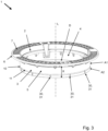
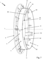
- the Fig. 1 to 3 each show in a perspective view a manhole cover frame 1 for a manhole cover arrangement (80, cf. Fig. 17 ) for use in new road construction and in renovation processes.
- This forms a manhole passage D running in a longitudinal direction L.
- the manhole cover frame 1 On the upper side, the manhole cover frame 1 has a closure element holder 2 for holding a closure element (81, cf. Fig. 17 ) of a manhole cover arrangement (80, cf. Fig. 17 ) with which the shaft passage D can be closed.
- the closure element holder 2 is radially enclosed by a frame collar 6, which forms an upper traffic area 7.
- a tubular frame apron 3 with an inner side 4, an outer side 5 and a length X in the longitudinal direction L is connected to the closure element holder 2 in the longitudinal direction L.
- the frame collar 6 projects radially beyond the frame apron 3.
- the shaft passage D runs through this frame apron 3 as well as the closure element holder 2 and the frame collar 6.
- the manhole cover frame 1 is made of cast iron in one piece, in particular including the locking element holder 2, the frame collar 6 and the frame apron 3.
- the frame apron 3 has a first predetermined breaking point 10 which runs transversely to the longitudinal direction L, and the frame apron 3 is divided into a first section A1 which borders on the closure element holder 2, and a breakable second section A2.
- the first predetermined breaking point 10 is designed as a predetermined breaking groove 11 on the outside 5 of the frame apron 3, which runs along the entire circumference of the frame apron 3.
- the frame apron 3 has a wall thickness W and the predetermined breaking groove 11 has a groove depth T1 which is at least 25%, and preferably at least 30%, of the wall thickness W of the frame apron 3 in the area of the predetermined breaking groove 11.
- this groove depth T1 should be a maximum of 60%, and preferably a maximum of 50%, of the wall thickness W of the frame apron 3 in the area of the predetermined breaking groove 11.
- the predetermined breaking groove 11 has a rounded groove cross-section.
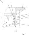
- the longitudinal section according to Fig.4 shows in particular a section through a manhole cover frame 1 according to the Fig.2 or 3 , which is why reference is made to their description regarding the further construction of the manhole cover frame 1.
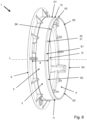
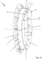
- Fig.2 deviates from the execution according to Fig.1 that the breakable second section A2 of the frame apron 3 has a single segmentation predetermined breaking point 30 which runs in the longitudinal direction L and divides the second section A2 in the circumferential direction of the frame apron 3, in particular such that the second section A2 is designed as an open ring or in circumferential segments (S1, S2, S3, S4, S5, S6, cf. Fig. 6 to 12 ) can be broken off, in particular irreversibly by breaking or breaking off.
- several segmentation predetermined breaking points 30 are evenly distributed over the circumference of the second section A2.
- the segmentation breaking points 30 each extend over the entire length between the first predetermined breaking point 10 and the end of the frame apron 3 which faces away from the closure element receptacle 2.
- the segmentation predetermined breaking points 30 each lie in a common plane with the longitudinal direction L or perpendicular to the first predetermined breaking point 10.
- the segmentation predetermined breaking points 30 are also each designed as a predetermined breaking groove 31 on the outside 5 of the frame apron 3.
- the predetermined breaking groove 31 of the segmentation predetermined breaking points 30 has a groove depth T3 which is at least 25%, and preferably at least 30%, of the wall thickness W of the frame apron 3 in the area of the predetermined breaking groove 31.
- this groove depth T3 of the predetermined breaking groove 31 of the segmentation predetermined breaking points 30 should be a maximum of 60%, and preferably a maximum of 50%, of the wall thickness W of the frame apron 3 in the area of the predetermined breaking groove 31.
- the predetermined breaking groove 31 of the segmentation predetermined breaking points 30 also has a rounded groove cross-section.
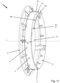
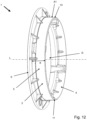
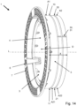
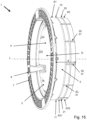
- the chess cover frames according to the Fig. 13 , 14 and 15 In this order, they essentially correspond to those in the Fig.1 , 2 and 3 are shown, which is why reference is first made to their description.
- the main difference in each case is that the frame apron 3 has a second predetermined breaking point 20 which runs transversely to the longitudinal direction L and divides the breakable second section A2 of the frame apron 3 into a breakable first partial section A21 and a breakable further partial section A22.
- the length X of the frame apron 3 can be shortened to two different values, in particular irreversibly by breaking off one or both partial sections A21, A22.
- the second predetermined breaking point 20 is located between the first predetermined breaking point 10 and the end of the frame apron 3 which faces away from the closure element holder 2.
- the second predetermined breaking point 20 is weaker than the first predetermined breaking point 10.
- the second predetermined breaking point 20 therefore breaks more easily than the first predetermined breaking point 10.
- the second predetermined breaking point 20 is designed as a predetermined breaking groove 21, which runs on the outside 5 of the frame apron 3 along the entire circumference of the frame apron 3.
- the predetermined breaking groove 21 of the second predetermined breaking point 20 also has a rounded groove cross-section.
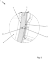
- the predetermined breaking groove 21 of the second predetermined breaking point 20 has a groove depth T2 which is at least 25%, and preferably at least 30%, of the wall thickness W of the Frame apron 3 in the area of the predetermined breaking groove 21. It is clear that the wall thickness W decreases with increasing distance from the closure element holder 2. However, the groove depth T2 of the predetermined breaking groove 21 of the second predetermined breaking point 20 should be a maximum of 60%, and preferably a maximum of 50%, of the wall thickness W of the frame apron 3 in the area of this predetermined breaking groove 11. Furthermore, it can be seen that the first predetermined breaking point 10 is slightly weaker than the segmentation predetermined breaking point 30 in the adjacent area. Likewise, the second predetermined breaking point 20 is slightly weaker than the segmentation predetermined breaking point 30 in the adjacent area. This promotes straight crack formation along the first and/or second predetermined breaking point 10, 20.
- the Fig. 13 , 14 , 15 and 16 in each case that the at least one segmentation predetermined breaking point 30 extends over the entire length of the second section A2, thus flush over the first and the second partial section A21, A22, in the longitudinal direction L.
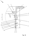
- Fig. 17 a longitudinal section through a shaft arrangement 90 with a shaft cover arrangement 80 on a shaft structure 91 is shown.
- the manhole cover arrangement 80 has a manhole cover frame 1, which, for example, as shown in the Fig. 1 to 16 A closure element 81 of the manhole cover arrangement 80 is inserted into the closure element receptacle 2 of the manhole cover frame 1 and thereby closes the manhole passage D.
- the manhole cover frame 1 is opposite the manhole structure 91 with the frame apron 3 and, if it were completely lowered, would sit on the manhole structure 91 and be supported on it. This is particularly the case because the frame apron 3 is longitudinally displaceable in a guide of a centering ring 92 of the manhole structure 91, the diameter of which is larger than the actual diameter of the manhole structure 91 at its upper end. The outer diameter of the frame apron 3 is therefore larger than the diameter of the manhole structure 91 below the centering ring 92.
- the manhole cover frame 1 To install the manhole cover frame 1, it is now first necessary to determine how high the available installation height for the manhole cover frame 1 is between the upper end of the manhole structure 91 and the desired installation height of the closure element holder 2 or the traffic area 7. The manhole cover frame 1 is then installed either without shortening the frame apron 3 if the available installation height is greater than a defined limit value. Alternatively, installation is only carried out after shortening the frame apron 3 in the longitudinal direction L by at least partially breaking off the second section A2 at a predetermined breaking point 10, 20 if the available Installation height is smaller than the defined limit. This can be done by hitting the outside 5 of the second section A2 with a hammer (see Fig. 1 to 16 ).
- Manhole cover frame A1 first section 2 Locking element holder A2 second part 3 Frame apron A21 first section 4 inside A22 further section 5 Outside D Shaft passage 6 Frame collar L Longitudinal direction 7 traffic area S1 Circumference segment S2 Circumference segment 10 first breaking point S3 Circumference segment 11 Breaking groove S4 Circumference segment S5 Circumference segment 20 second breaking point S6 Circumference segment 21 Breaking groove T1 Groove depth T2 Groove depth 30 Segmentation breaking point T3 Groove depth 31 Breaking groove W Wall thickness X length 80 Manhole cover arrangement 81 Locking element 90 Shaft arrangement 91 Shaft construction 92 Centering ring
Landscapes
- Engineering & Computer Science (AREA)
- Environmental & Geological Engineering (AREA)
- Life Sciences & Earth Sciences (AREA)
- General Life Sciences & Earth Sciences (AREA)
- Mining & Mineral Resources (AREA)
- Paleontology (AREA)
- Civil Engineering (AREA)
- General Engineering & Computer Science (AREA)
- Structural Engineering (AREA)
- Underground Structures, Protecting, Testing And Restoring Foundations (AREA)
Applications Claiming Priority (1)
| Application Number | Priority Date | Filing Date | Title |
|---|---|---|---|
| DE102018109220.2A DE102018109220A1 (de) | 2018-04-18 | 2018-04-18 | Schachtabdeckungsrahmen, Schachtabdeckungsanordnung, Schachtanordnung und Installationsverfahren |
Publications (2)
| Publication Number | Publication Date |
|---|---|
| EP3556944A1 EP3556944A1 (de) | 2019-10-23 |
| EP3556944B1 true EP3556944B1 (de) | 2024-05-01 |
Family
ID=65904196
Family Applications (1)
| Application Number | Title | Priority Date | Filing Date |
|---|---|---|---|
| EP19164383.2A Active EP3556944B1 (de) | 2018-04-18 | 2019-03-21 | Schachtabdeckungsrahmen, schachtabdeckungsanordnung, schachtanordnung und installationsverfahren |
Country Status (3)
| Country | Link |
|---|---|
| EP (1) | EP3556944B1 (pl) |
| DE (2) | DE102018109220A1 (pl) |
| PL (1) | PL3556944T3 (pl) |
Families Citing this family (1)
| Publication number | Priority date | Publication date | Assignee | Title |
|---|---|---|---|---|
| CN115110911B (zh) * | 2022-07-14 | 2024-05-14 | 东营大明石油工程科技开发有限责任公司 | 一种井口对接装置及其对接方法 |
Citations (2)
| Publication number | Priority date | Publication date | Assignee | Title |
|---|---|---|---|---|
| US6311433B1 (en) * | 2000-09-05 | 2001-11-06 | David J. Zdroik | Adjustable manhole/catch basin structure |
| DE102006056146A1 (de) * | 2006-11-28 | 2008-06-05 | Aco Severin Ahlmann Gmbh & Co. Kg | Vorrichtung zum Einbau in eine Rohrleitung |
Family Cites Families (4)
| Publication number | Priority date | Publication date | Assignee | Title |
|---|---|---|---|---|
| DE9215759U1 (de) * | 1992-11-20 | 1993-03-04 | Passavant-Werke AG, 6209 Aarbergen | Aus Rahmen und klappbarem Deckel oder Rost bestehender Kanalisationsartikel |
| DE59913773D1 (de) * | 1998-04-30 | 2006-09-28 | Gerhard Schone | Vorrichtung zum Höhenausgleich zwischen Schachthals und Fahrbahnoberfläche und Anordnung der Vorrichtung in einer Fahrbahnkonstruktion |
| EP2317197B1 (de) * | 2009-11-02 | 2012-06-06 | R. Nussbaum AG | Formstabiles Rohr zum Führen von Wasser |
| DE102015106750A1 (de) * | 2015-04-30 | 2016-11-03 | ACO Severin Ahlmann GmbH & Co Kommanditgesellschaft | Schachtabdeckung |
-
2018
- 2018-04-18 DE DE102018109220.2A patent/DE102018109220A1/de not_active Withdrawn
-
2019
- 2019-03-21 DE DE202019005915.6U patent/DE202019005915U1/de active Active
- 2019-03-21 PL PL19164383.2T patent/PL3556944T3/pl unknown
- 2019-03-21 EP EP19164383.2A patent/EP3556944B1/de active Active
Patent Citations (2)
| Publication number | Priority date | Publication date | Assignee | Title |
|---|---|---|---|---|
| US6311433B1 (en) * | 2000-09-05 | 2001-11-06 | David J. Zdroik | Adjustable manhole/catch basin structure |
| DE102006056146A1 (de) * | 2006-11-28 | 2008-06-05 | Aco Severin Ahlmann Gmbh & Co. Kg | Vorrichtung zum Einbau in eine Rohrleitung |
Also Published As
| Publication number | Publication date |
|---|---|
| PL3556944T3 (pl) | 2024-10-28 |
| DE102018109220A1 (de) | 2019-10-24 |
| EP3556944A1 (de) | 2019-10-23 |
| DE202019005915U1 (de) | 2023-04-05 |
Similar Documents
| Publication | Publication Date | Title |
|---|---|---|
| EP2839083B1 (de) | Rammspitze für pfahl | |
| EP3556944B1 (de) | Schachtabdeckungsrahmen, schachtabdeckungsanordnung, schachtanordnung und installationsverfahren | |
| EP3115511A1 (de) | Verfahren zur herstellung einer überschnittenen bohrpfahlwand | |
| AT510951B1 (de) | Pfahl mit einem im wesentlichen zylindrischen schaft | |
| EP2902645B1 (de) | Schraube zum Einschrauben in ein Bohrloch und Vorspann-Anordnung mit einer derartigen in das Bohrloch eingeschraubten Schraube | |
| EP1460277B1 (de) | Verankerungshülse für Schutzgeländer | |
| EP1907714B1 (de) | Gewindeschneidender betonanker | |
| DE202010004381U1 (de) | Druckrohr sowie daraus hergestellter Erdanker | |
| EP0262444A1 (de) | Verankerungselement, insbesondere Dübel | |
| DE102013015502B4 (de) | Verfahren zum baulich lntegrieren eines Aufsetzstücks gemeinsam mit einer Leitung in ein Wand- oder Bodenelement | |
| EP3508667B1 (de) | Verfahren zum verbinden eines distanzhalters mit einem anschlusseisen, eine abstand- und anschlaghalteranordnung, ein keil und ein halter | |
| CH711156B1 (de) | Anschlagelement, Positioniervorrichtung mit mindestens einem solchen Anschlagelement und Verfahren zur Positionierung von Wandschalungen. | |
| DE202013006822U1 (de) | Abstandhalter für mit einem Basismaterial herzustellende Bauteile mit textilen Bewehrungslagen | |
| DE102004053934B4 (de) | Vorrichtung zum Durchführen wenigstens eines Kabels oder Rohres durch eine bodenseitige Betonplatte eines Gebäudes | |
| EP0315277A1 (de) | Verfahren und Vorrichtung zur Prüfung von erdverlegten Kanalisationsrohren aus Beton | |
| EP3107166B1 (de) | Durchführung zum hindurchführen einer leitung durch ein wand- oder bodenelement | |
| EP3228750B1 (de) | Verfahren und bodendübelsystem zur pfostenbefestigung | |
| AT516176B1 (de) | Seitenwandung für eine Überlaufrinne | |
| DE9307284U1 (de) | Verschlußteil für Betonwand oder Betondecke | |
| EP3784835B1 (de) | Anschlussvorrichtung, ablaufsystem und verfahren | |
| DE202021003890U1 (de) | Futterrohr zum Durchführen einer oder mehrerer Leitungen durch einen Wandabschnitt | |
| DE29611837U1 (de) | Vorrichtung zum Versetzen von Kellerfenstergewänden | |
| EP2813622B1 (de) | Pfahlschuh für einen Rammpfahl und Gründungselement | |
| DE3437639C1 (de) | Abstandhalter für die Bewehrung einer Stahlbetonplatte | |
| DE9016348U1 (de) | Einbauhilfe für Steigeisen |
Legal Events
| Date | Code | Title | Description |
|---|---|---|---|
| PUAI | Public reference made under article 153(3) epc to a published international application that has entered the european phase |
Free format text: ORIGINAL CODE: 0009012 |
|
| STAA | Information on the status of an ep patent application or granted ep patent |
Free format text: STATUS: THE APPLICATION HAS BEEN PUBLISHED |
|
| AK | Designated contracting states |
Kind code of ref document: A1 Designated state(s): AL AT BE BG CH CY CZ DE DK EE ES FI FR GB GR HR HU IE IS IT LI LT LU LV MC MK MT NL NO PL PT RO RS SE SI SK SM TR |
|
| AX | Request for extension of the european patent |
Extension state: BA ME |
|
| STAA | Information on the status of an ep patent application or granted ep patent |
Free format text: STATUS: REQUEST FOR EXAMINATION WAS MADE |
|
| 17P | Request for examination filed |
Effective date: 20200410 |
|
| RBV | Designated contracting states (corrected) |
Designated state(s): AL AT BE BG CH CY CZ DE DK EE ES FI FR GB GR HR HU IE IS IT LI LT LU LV MC MK MT NL NO PL PT RO RS SE SI SK SM TR |
|
| STAA | Information on the status of an ep patent application or granted ep patent |
Free format text: STATUS: EXAMINATION IS IN PROGRESS |
|
| 17Q | First examination report despatched |
Effective date: 20211012 |
|
| GRAP | Despatch of communication of intention to grant a patent |
Free format text: ORIGINAL CODE: EPIDOSNIGR1 |
|
| STAA | Information on the status of an ep patent application or granted ep patent |
Free format text: STATUS: GRANT OF PATENT IS INTENDED |
|
| INTG | Intention to grant announced |
Effective date: 20240112 |
|
| GRAS | Grant fee paid |
Free format text: ORIGINAL CODE: EPIDOSNIGR3 |
|
| GRAA | (expected) grant |
Free format text: ORIGINAL CODE: 0009210 |
|
| STAA | Information on the status of an ep patent application or granted ep patent |
Free format text: STATUS: THE PATENT HAS BEEN GRANTED |
|
| AK | Designated contracting states |
Kind code of ref document: B1 Designated state(s): AL AT BE BG CH CY CZ DE DK EE ES FI FR GB GR HR HU IE IS IT LI LT LU LV MC MK MT NL NO PL PT RO RS SE SI SK SM TR |
|
| REG | Reference to a national code |
Ref country code: GB Ref legal event code: FG4D Free format text: NOT ENGLISH |
|
| REG | Reference to a national code |
Ref country code: CH Ref legal event code: EP |
|
| REG | Reference to a national code |
Ref country code: DE Ref legal event code: R096 Ref document number: 502019011155 Country of ref document: DE |
|
| REG | Reference to a national code |
Ref country code: IE Ref legal event code: FG4D Free format text: LANGUAGE OF EP DOCUMENT: GERMAN |
|
| REG | Reference to a national code |
Ref country code: NL Ref legal event code: FP |
|
| REG | Reference to a national code |
Ref country code: LT Ref legal event code: MG9D |
|
| PG25 | Lapsed in a contracting state [announced via postgrant information from national office to epo] |
Ref country code: IS Free format text: LAPSE BECAUSE OF FAILURE TO SUBMIT A TRANSLATION OF THE DESCRIPTION OR TO PAY THE FEE WITHIN THE PRESCRIBED TIME-LIMIT Effective date: 20240901 |
|
| PG25 | Lapsed in a contracting state [announced via postgrant information from national office to epo] |
Ref country code: BG Free format text: LAPSE BECAUSE OF FAILURE TO SUBMIT A TRANSLATION OF THE DESCRIPTION OR TO PAY THE FEE WITHIN THE PRESCRIBED TIME-LIMIT Effective date: 20240501 |
|
| PG25 | Lapsed in a contracting state [announced via postgrant information from national office to epo] |
Ref country code: HR Free format text: LAPSE BECAUSE OF FAILURE TO SUBMIT A TRANSLATION OF THE DESCRIPTION OR TO PAY THE FEE WITHIN THE PRESCRIBED TIME-LIMIT Effective date: 20240501 Ref country code: FI Free format text: LAPSE BECAUSE OF FAILURE TO SUBMIT A TRANSLATION OF THE DESCRIPTION OR TO PAY THE FEE WITHIN THE PRESCRIBED TIME-LIMIT Effective date: 20240501 |
|
| PG25 | Lapsed in a contracting state [announced via postgrant information from national office to epo] |
Ref country code: GR Free format text: LAPSE BECAUSE OF FAILURE TO SUBMIT A TRANSLATION OF THE DESCRIPTION OR TO PAY THE FEE WITHIN THE PRESCRIBED TIME-LIMIT Effective date: 20240802 |
|
| PG25 | Lapsed in a contracting state [announced via postgrant information from national office to epo] |
Ref country code: PT Free format text: LAPSE BECAUSE OF FAILURE TO SUBMIT A TRANSLATION OF THE DESCRIPTION OR TO PAY THE FEE WITHIN THE PRESCRIBED TIME-LIMIT Effective date: 20240902 |
|
| PG25 | Lapsed in a contracting state [announced via postgrant information from national office to epo] |
Ref country code: ES Free format text: LAPSE BECAUSE OF FAILURE TO SUBMIT A TRANSLATION OF THE DESCRIPTION OR TO PAY THE FEE WITHIN THE PRESCRIBED TIME-LIMIT Effective date: 20240501 |
|
| PG25 | Lapsed in a contracting state [announced via postgrant information from national office to epo] |
Ref country code: PT Free format text: LAPSE BECAUSE OF FAILURE TO SUBMIT A TRANSLATION OF THE DESCRIPTION OR TO PAY THE FEE WITHIN THE PRESCRIBED TIME-LIMIT Effective date: 20240902 Ref country code: NO Free format text: LAPSE BECAUSE OF FAILURE TO SUBMIT A TRANSLATION OF THE DESCRIPTION OR TO PAY THE FEE WITHIN THE PRESCRIBED TIME-LIMIT Effective date: 20240801 Ref country code: IS Free format text: LAPSE BECAUSE OF FAILURE TO SUBMIT A TRANSLATION OF THE DESCRIPTION OR TO PAY THE FEE WITHIN THE PRESCRIBED TIME-LIMIT Effective date: 20240901 Ref country code: HR Free format text: LAPSE BECAUSE OF FAILURE TO SUBMIT A TRANSLATION OF THE DESCRIPTION OR TO PAY THE FEE WITHIN THE PRESCRIBED TIME-LIMIT Effective date: 20240501 Ref country code: GR Free format text: LAPSE BECAUSE OF FAILURE TO SUBMIT A TRANSLATION OF THE DESCRIPTION OR TO PAY THE FEE WITHIN THE PRESCRIBED TIME-LIMIT Effective date: 20240802 Ref country code: FI Free format text: LAPSE BECAUSE OF FAILURE TO SUBMIT A TRANSLATION OF THE DESCRIPTION OR TO PAY THE FEE WITHIN THE PRESCRIBED TIME-LIMIT Effective date: 20240501 Ref country code: ES Free format text: LAPSE BECAUSE OF FAILURE TO SUBMIT A TRANSLATION OF THE DESCRIPTION OR TO PAY THE FEE WITHIN THE PRESCRIBED TIME-LIMIT Effective date: 20240501 Ref country code: BG Free format text: LAPSE BECAUSE OF FAILURE TO SUBMIT A TRANSLATION OF THE DESCRIPTION OR TO PAY THE FEE WITHIN THE PRESCRIBED TIME-LIMIT Effective date: 20240501 Ref country code: RS Free format text: LAPSE BECAUSE OF FAILURE TO SUBMIT A TRANSLATION OF THE DESCRIPTION OR TO PAY THE FEE WITHIN THE PRESCRIBED TIME-LIMIT Effective date: 20240801 |
|
| PG25 | Lapsed in a contracting state [announced via postgrant information from national office to epo] |
Ref country code: DK Free format text: LAPSE BECAUSE OF FAILURE TO SUBMIT A TRANSLATION OF THE DESCRIPTION OR TO PAY THE FEE WITHIN THE PRESCRIBED TIME-LIMIT Effective date: 20240501 |
|
| PG25 | Lapsed in a contracting state [announced via postgrant information from national office to epo] |
Ref country code: EE Free format text: LAPSE BECAUSE OF FAILURE TO SUBMIT A TRANSLATION OF THE DESCRIPTION OR TO PAY THE FEE WITHIN THE PRESCRIBED TIME-LIMIT Effective date: 20240501 |
|
| PG25 | Lapsed in a contracting state [announced via postgrant information from national office to epo] |
Ref country code: RO Free format text: LAPSE BECAUSE OF FAILURE TO SUBMIT A TRANSLATION OF THE DESCRIPTION OR TO PAY THE FEE WITHIN THE PRESCRIBED TIME-LIMIT Effective date: 20240501 Ref country code: SK Free format text: LAPSE BECAUSE OF FAILURE TO SUBMIT A TRANSLATION OF THE DESCRIPTION OR TO PAY THE FEE WITHIN THE PRESCRIBED TIME-LIMIT Effective date: 20240501 |
|
| PG25 | Lapsed in a contracting state [announced via postgrant information from national office to epo] |
Ref country code: SM Free format text: LAPSE BECAUSE OF FAILURE TO SUBMIT A TRANSLATION OF THE DESCRIPTION OR TO PAY THE FEE WITHIN THE PRESCRIBED TIME-LIMIT Effective date: 20240501 |
|
| PG25 | Lapsed in a contracting state [announced via postgrant information from national office to epo] |
Ref country code: SM Free format text: LAPSE BECAUSE OF FAILURE TO SUBMIT A TRANSLATION OF THE DESCRIPTION OR TO PAY THE FEE WITHIN THE PRESCRIBED TIME-LIMIT Effective date: 20240501 Ref country code: SK Free format text: LAPSE BECAUSE OF FAILURE TO SUBMIT A TRANSLATION OF THE DESCRIPTION OR TO PAY THE FEE WITHIN THE PRESCRIBED TIME-LIMIT Effective date: 20240501 Ref country code: RO Free format text: LAPSE BECAUSE OF FAILURE TO SUBMIT A TRANSLATION OF THE DESCRIPTION OR TO PAY THE FEE WITHIN THE PRESCRIBED TIME-LIMIT Effective date: 20240501 Ref country code: EE Free format text: LAPSE BECAUSE OF FAILURE TO SUBMIT A TRANSLATION OF THE DESCRIPTION OR TO PAY THE FEE WITHIN THE PRESCRIBED TIME-LIMIT Effective date: 20240501 Ref country code: DK Free format text: LAPSE BECAUSE OF FAILURE TO SUBMIT A TRANSLATION OF THE DESCRIPTION OR TO PAY THE FEE WITHIN THE PRESCRIBED TIME-LIMIT Effective date: 20240501 |
|
| REG | Reference to a national code |
Ref country code: DE Ref legal event code: R097 Ref document number: 502019011155 Country of ref document: DE |
|
| PG25 | Lapsed in a contracting state [announced via postgrant information from national office to epo] |
Ref country code: IT Free format text: LAPSE BECAUSE OF FAILURE TO SUBMIT A TRANSLATION OF THE DESCRIPTION OR TO PAY THE FEE WITHIN THE PRESCRIBED TIME-LIMIT Effective date: 20240501 |
|
| PLBE | No opposition filed within time limit |
Free format text: ORIGINAL CODE: 0009261 |
|
| STAA | Information on the status of an ep patent application or granted ep patent |
Free format text: STATUS: NO OPPOSITION FILED WITHIN TIME LIMIT |
|
| 26N | No opposition filed |
Effective date: 20250204 |
|
| PGFP | Annual fee paid to national office [announced via postgrant information from national office to epo] |
Ref country code: DE Payment date: 20250331 Year of fee payment: 7 |
|
| PGFP | Annual fee paid to national office [announced via postgrant information from national office to epo] |
Ref country code: NL Payment date: 20250319 Year of fee payment: 7 |
|
| PGFP | Annual fee paid to national office [announced via postgrant information from national office to epo] |
Ref country code: LU Payment date: 20250320 Year of fee payment: 7 |
|
| PG25 | Lapsed in a contracting state [announced via postgrant information from national office to epo] |
Ref country code: SI Free format text: LAPSE BECAUSE OF FAILURE TO SUBMIT A TRANSLATION OF THE DESCRIPTION OR TO PAY THE FEE WITHIN THE PRESCRIBED TIME-LIMIT Effective date: 20240501 |
|
| PGFP | Annual fee paid to national office [announced via postgrant information from national office to epo] |
Ref country code: AT Payment date: 20250320 Year of fee payment: 7 Ref country code: LV Payment date: 20250320 Year of fee payment: 7 |
|
| PGFP | Annual fee paid to national office [announced via postgrant information from national office to epo] |
Ref country code: PL Payment date: 20250317 Year of fee payment: 7 Ref country code: CZ Payment date: 20250317 Year of fee payment: 7 |
|
| PGFP | Annual fee paid to national office [announced via postgrant information from national office to epo] |
Ref country code: CH Payment date: 20250401 Year of fee payment: 7 |
|
| PG25 | Lapsed in a contracting state [announced via postgrant information from national office to epo] |
Ref country code: SE Free format text: LAPSE BECAUSE OF FAILURE TO SUBMIT A TRANSLATION OF THE DESCRIPTION OR TO PAY THE FEE WITHIN THE PRESCRIBED TIME-LIMIT Effective date: 20240501 |
|
| PG25 | Lapsed in a contracting state [announced via postgrant information from national office to epo] |
Ref country code: MC Free format text: LAPSE BECAUSE OF FAILURE TO SUBMIT A TRANSLATION OF THE DESCRIPTION OR TO PAY THE FEE WITHIN THE PRESCRIBED TIME-LIMIT Effective date: 20240501 |
|
| GBPC | Gb: european patent ceased through non-payment of renewal fee |
Effective date: 20250321 |
|
| REG | Reference to a national code |
Ref country code: BE Ref legal event code: MM Effective date: 20250331 |