EP2813622B1 - Pfahlschuh für einen Rammpfahl und Gründungselement - Google Patents
Pfahlschuh für einen Rammpfahl und Gründungselement Download PDFInfo
- Publication number
- EP2813622B1 EP2813622B1 EP13171686.2A EP13171686A EP2813622B1 EP 2813622 B1 EP2813622 B1 EP 2813622B1 EP 13171686 A EP13171686 A EP 13171686A EP 2813622 B1 EP2813622 B1 EP 2813622B1
- Authority
- EP
- European Patent Office
- Prior art keywords
- pile
- tube
- shoe
- pile shoe
- pile tube
- Prior art date
- Legal status (The legal status is an assumption and is not a legal conclusion. Google has not performed a legal analysis and makes no representation as to the accuracy of the status listed.)
- Active
Links
Images

Classifications
-
- E—FIXED CONSTRUCTIONS
- E02—HYDRAULIC ENGINEERING; FOUNDATIONS; SOIL SHIFTING
- E02D—FOUNDATIONS; EXCAVATIONS; EMBANKMENTS; UNDERGROUND OR UNDERWATER STRUCTURES
- E02D5/00—Bulkheads, piles, or other structural elements specially adapted to foundation engineering
- E02D5/72—Pile shoes
Definitions
- the invention relates to a pile shoe for a driven pile, wherein the pile shoe has a propulsion side, which points in a driving direction, and a back with an abutment, which is designed for mounting and supporting a pile tube, according to the preamble of claim 1.
- the invention further relates a foundation element according to the preamble of claim 10.
- Such piles are used as foundation elements for buildings or soil improvement in loose or soft soils.
- the driven pile is driven into the ground essentially without excavation of soil material, in particular vibrated or driven in by means of vibrators or rams.
- a pile tube which can be composed of several, usually the same structure pile pipe elements. In this way, the pile can be adjusted depending on the application in its length.
- a so-called pile shoe At the bottom end of the pile tube is as a final element a so-called pile shoe. Its outer diameter is usually larger than the diameter of the underlying pile tube.
- Such a pile is, for example, in the GB 2 351 516 A described.
- the pile pile is constructed from several pile tube segments, which each have a pipe extension at its rear end of the pipe. In the respective pipe extension, a bottom, smaller-diameter end of an adjacent pile pipe element can be inserted. At the bottom end of a conical pile shoe is attached. Passages for radial exit of the hardenable mass are provided at different positions along each pile tube element. The introduction of such radial passages in a cylinder wall, for example, during the casting of the tubular element is complicated. In addition, a recess is often desired only at the lower end, so that the well reliably fills up from below.
- the invention has for its object to provide a technical teaching, with which on the one hand a pile pile is inexpensive to produce and on the other hand, a foundation element can be reliably manufactured with such a pile pile.
- the pile shoe according to the invention is characterized in that at least one radially extending passage is arranged on the abutment, which is formed for the passage of a filling material from the interior of the pile tube to the outside of the pile tube.
- a basic idea of the invention is not to provide a passage for the hardenable mass from the pile tube inner side to the pile tube outside on the pile tube, but to form a passageway on the pile shoe.
- the pile pile can thus be formed in a cost-effective manner from one or more identically constructed pile tube elements, without them necessarily having to have a passage.
- the pile tube can be made so overall easy and with high strength.
- one or more radially directed passages are provided on the pile shoe separate pile shoe.
- the flowable hardenable mass can thus emerge directly from the tube interior into the outer free space at the lower end of the pile tube, so that the annular outer space can reliably fill from below with curable material.
- the inventively designed pile shoe can also be used with pile tube elements, which additionally have passages.
- An inexpensive embodiment of the invention is that the propulsion side of the pile shoe is designed plate-shaped. A particularly good penetration into the ground is inventively achieved in that the propulsion side is conical.
- the outer diameter of the approximately circular pile shoe is greater than the outer diameter of the alsforden pile tube, so that when driving into the ground, an annular outer space is formed.
- the at least one radially extending passage may be formed as a tunnel-like channel which extends within the pile shoe and has an inner access opening and a radially outer outlet opening.
- the abutment has a flat support surface in which at least one recess is made to form the passage.
- the pile shoe may thus be made, for example, as a simple forging or casting.
- the Pile shoe is preferably made of metal, in particular steel or gray cast iron, or concrete.
- the support surface is circular or annular and is interrupted by the one or more recesses.
- a uniform strength is achieved according to the invention in that the front and the back of the pile shoe are formed substantially symmetrically to a central axis.
- a basic shape of the pile shoe is rotationally symmetrical.
- the pile shoe can also be square, polygonal or formed with another, deviating from a circular shape.
- a single radial passage is formed in the pile shoe.
- a particularly efficient and uniform filling of the outer annular space of the borehole is ensured according to a further embodiment of the invention in that a plurality of passages are provided, which are distributed uniformly over the circumference of the abutment.
- a plurality of passages are provided, which are distributed uniformly over the circumference of the abutment.
- 2, 3 or 4 radially extending passages are formed.
- the one or more passages have a radial extent which is greater than the thickness of the pipe wall of the patch pile pipe. This ensures safe flow around the pile tube in the area of the pile shoe from the inside to the outside.
- a positionally accurate introduction of the driven pile is supported according to the invention in that a centering device is provided on the back of the pile shoe, through which the pile tube is held centrally to the center axis of the pile shoe.
- This can be an interior and / or exterior centering.
- the centering device has at least two radially directed webs, which taper conically towards the center axis. This is an internal centering, preferably 3 or 4 evenly distributed over the circumference radial webs are arranged.
- the centering device has a base whose outer circumference is adapted to an inner side of the pile tube.
- the base may in principle have an annular shoulder or ring-segment-shaped shoulders, wherein the outer ring diameter is adapted to the inner diameter of the aufcutden pile tube, in particular forms a clearance fit with this.
- annular outer wall is arranged on the rear side, with an outer side of the pile tube being spaced from the inner side of the peripheral wall when the pile tube is mounted, thereby forming a free space.
- the free space is designed in particular annular.
- the one or more radial passages open into this annular space.
- the annular outer wall extends axially only in a partial region of the pile length and, in particular in particularly soft and unstable soils, ensures that as free as possible an escape of the hardenable mass, in particular on a cement basis, from the passage into the surrounding annular space is made possible.
- a foundation element in the bottom with a driven pile which has a pile tube, which is composed of one or more pile tube elements, and a pile shoe at the bottom end of the pile tube.
- This foundation element is characterized in that a pile shoe is provided according to the invention described above.
- the pile tube or the pile tube elements for forming the pile tube and the pile shoe may be formed of metal, in particular steel or gray cast iron, or of concrete.
- these each have at their bottom end a taper and at its bottom end facing away from a corresponding diameter extension, so that the pile tube elements can be reliably plugged together.
- a preferred embodiment of the foundation element according to the invention is that the driven pile is embedded in a hardened mass.
- the Hardened mass is in particular a cement paste, which is arranged inside and outside of the driven pile due to a passage through the passage at the pile shoe.
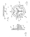
- the pile shoe according to Fig. 1 is formed substantially circular disc-shaped with a flat propulsion side 12, which is directed in a driving direction.
- a centering device 30 is formed centrally with respect to a center axis 24.
- the centering device 30 has three plate-shaped webs 32, which extend from a common center region in a star-shaped manner radially outwards.
- the three webs 32 are evenly distributed to the circular outer periphery 22 of the pile shoe 10 at an angle of 120 ° to each other.
- the identically formed webs 32 each have an arcuate outer edge 36, so that the webs 32 taper from a lower base 34 up to the center axis 24 out, as from Fig. 2 is apparent.
- an abutment 16 is formed with a flat support surface 18, from which the centering device 30 extends upward.
- the level Support surface 18 is annular on an elevated circular disk-shaped plateau 26 and extends around the centering device 30 around.
- the annular bearing surface 18 has a radial extent, which is designed to receive a pile tube, not shown.
- the pile tube has an inner diameter which corresponds approximately to the spanned by the base 34 of the webs 32 outer diameter.
- the annular bearing surface 18 is interrupted by three mutually offset by 120 ° recesses to form passages 20.
- the passages 20 represent segment-shaped recesses which have a radial extent which is greater than a wall thickness of the pile pipe to be erected. There remain so axially directed inlet and outlet openings. In this way, it is ensured in a patch on the support surface 18 post tube that a supplied within the pile tube curable material can flow through the passages 20 radially outwardly to the outside of the pile tube.
- the borehole diameter corresponds approximately to the outer periphery 22 of the pile shoe 10.
- This annular space is filled by the hardenable mass, in particular cement-based, which flows through the passages 20 into the annular outer space.
- the flat bearing surface 18 of the abutment 16 is formed on an elevated circular disk-shaped plateau 26.
- the circular disk-shaped plateau 26 is smaller in diameter relative to the circular drive side 12, so that an outer shoulder 28 is formed.
- FIGS. 4 to 6 A modified embodiment of a pile shoe 10 according to the invention is in the FIGS. 4 to 6 shown. This corresponds largely to the embodiment according to the FIGS. 1 to 3 , In contrast to the previous embodiment, however, the circular disk-shaped plateau 26 is formed with a smaller diameter, so that the three passages 20 open directly into the shoulder 28. In this way, the passages 20 also have a radial outlet opening 21, in particular from the FIGS. 5 and 6 can be seen.
- the centering device 30 corresponds to the centering device described above, wherein the arrangement of the three webs 32 offset by 60 ° to the arrangement of the three passages 20, as shown in the previous embodiment.
Landscapes
- Engineering & Computer Science (AREA)
- Structural Engineering (AREA)
- Life Sciences & Earth Sciences (AREA)
- General Life Sciences & Earth Sciences (AREA)
- Mining & Mineral Resources (AREA)
- Paleontology (AREA)
- Civil Engineering (AREA)
- General Engineering & Computer Science (AREA)
- Piles And Underground Anchors (AREA)
Description
- Die Erfindung betrifft einen Pfahlschuh für einen Rammpfahl, wobei der Pfahlschuh eine Vortriebseite, welche in eine Rammrichtung weist, und eine Rückseite mit einem Widerlager aufweist, welches zum Aufsetzen und Abstützen eines Pfahlrohres ausgebildet ist, gemäß dem Oberbegriff des Anspruchs 1. Die Erfindung betrifft weiter ein Gründungselement nach dem Oberbegriff des Anspruchs 10.
- Derartige Rammpfähle werden als Gründungselemente für Bauwerke oder zur Bodenverbesserung in lockeren oder weichen Böden eingesetzt. Der Rammpfahl wird dabei im Wesentlichen ohne Aushub von Bodenmaterial in den Boden eingetrieben, insbesondere mittels Rüttlern oder Rammen eingerüttelt oder eingerammt.
- Zum Bilden des Rammpfahles ist ein Pfahlrohr vorgesehen, welches aus mehreren, üblicherweise gleich aufgebauten Pfahlrohrelementen zusammengesetzt werden kann. Auf diese Weise kann der Rammpfahl je nach Anwendungsfall in seiner Länge angepasst werden. Am bodenseitigen Ende des Pfahlrohres befindet sich als Abschlusselement ein sogenannter Pfahlschuh. Dessen Außendurchmesser ist üblicherweise größer als der Durchmesser des dahinterliegenden Pfahlrohres. Beim Eintreiben des Rammpfahles wird aufgrund des durchmessergrößeren Pfahlschuhs ein gewisser Freiraum zwischen dem durch Eintreiben bewirkten Bohrloch und dem darin angeordneten Pfahlrohr erzeugt. Über den inneren Rohrhohlraum des Pfahlrohres kann von der Bodenoberseite eine aushärtbare Masse, insbesondere auf Zementbasis, in das Bohrloch eingeleitet werden. Über Durchgänge am Pfahlrohr kann die fließfähige aushärtbare Masse auch in den Freiraum an der Außenseite des Pfahlrohres dringen, so dass nach Aushärten der aushärtbaren Masse das Pfahlrohr als Versteifungs- oder Verstärkungselement in dem Gründungspfahl verbleibt.
- Ein derartiger Rammpfahl ist beispielsweise in der
GB 2 351 516 A - Es ist bekannt, einen Rammpfahl aus Pfahlrohrelementen aufzubauen, welche zunächst gar keinen radialen Durchbruch aufweisen. Ein derartiger Rammpfahl wird beispielsweise in der
DE 94 14 813 U1 oder in derNL 103 2168 C - Ein derartiges nachträgliches Einbringen von Ausnehmungen ist jedoch zeit- und arbeitsaufwändig. Wird zudem eine Ausnehmung nicht in einer ausreichenden Größe hergestellt, kann der Durchtritt von aushärtbarer Masse durch das Pfahlrohr an die Außenseite beeinträchtigt sein. Dies kann dazu führen, dass der außenliegende Freiraum am Pfahlrohr nicht vollständig verfüllt ist, wodurch der Kontakt zum umgebenden Erdreich und damit die Tragfähigkeit des Gründungselementes beeinträchtigt sein können.
- Der Erfindung liegt die Aufgabe zugrunde, eine technische Lehre anzugeben, mit welcher einerseits ein Rammpfahl kostengünstig herstellbar ist und andererseits ein Gründungselement mit einem solchen Rammpfahl zuverlässig gefertigt werden kann.
- Die Erfindung wird durch einen Pfahlschuh für einen Rammpfahl mit den Merkmalen des Anspruchs 1 gelöst. Bevorzugte Ausführungsformen des erfindungsgemäßen Pfahlschuhes sind in den abhängigen Ansprüchen angegeben.
- Der erfindungsgemäße Pfahlschuh ist dadurch gekennzeichnet, dass an dem Widerlager mindestens ein radial verlaufender Durchgang angeordnet ist, welcher zum Durchtritt eines Füllmateriales aus dem Innern des Pfahlrohres zur Außenseite des Pfahlrohres ausgebildet ist.
- Ein Grundgedanke der Erfindung liegt darin, einen Durchgang für die aushärtbare Masse von der Pfahlrohrinnenseite zur Pfahlrohraußenseite nicht am Pfahlrohr vorzusehen, sondern einen Durchgang am Pfahlschuh auszubilden. Der Rammpfahl kann so in einer kostengünstigen Weise aus einem oder mehreren gleich aufgebauten Pfahlrohrelementen gebildet sein, ohne dass diese zwingend einen Durchgang aufweisen müssen. Das Pfahlrohr kann so insgesamt einfach und mit hoher Festigkeit gefertigt werden.
- Gemäß der Erfindung werden ein oder mehrere radial gerichtete Durchgänge an dem vom Pfahlrohr separaten Pfahlschuh vorgesehen. Die fließfähige aushärtbare Masse kann somit unmittelbar am unteren Ende des Pfahlrohres aus dem Rohrinnenraum in den äußeren Freiraum austreten, so dass sich der ringförmige äußere Freiraum zuverlässig von unten mit aushärtbarer Masse füllen kann. Selbstverständlich kann der erfindungsgemäß ausgebildete Pfahlschuh auch mit Pfahlrohrelementen verwendet werden, welche zusätzlich Durchgänge aufweisen.
- Eine kostengünstige Ausführungsform der Erfindung besteht darin, dass die Vortriebsseite des Pfahlschuhes plattenförmig gestaltet ist. Ein besonders gutes Vordringen in den Boden wird erfindungsgemäß dadurch erreicht, dass die Vortriebsseite konisch ausgebildet ist. Der Außendurchmesser des etwa kreisförmigen Pfahlschuhs ist größer als der Außendurchmesser des aufzusetzenden Pfahlrohrs, so dass beim Eintreiben in den Boden ein ringförmiger äußerer Freiraum gebildet wird.
- Grundsätzlich kann der mindestens eine radial verlaufende Durchgang als ein tunnelartiger Kanal ausgebildet sein, welcher sich innerhalb des Pfahlschuhes erstreckt und eine innere Zutrittsöffnung und eine radial äußere Austrittsöffnung aufweist. Eine in fertigungstechnischer Hinsicht besonders effiziente Ausgestaltung besteht darin, dass das Widerlager eine ebene Auflagefläche aufweist, in welcher zum Bilden des Durchganges mindestens eine Ausnehmung eingebracht ist. Der Pfahlschuh kann so beispielsweise als ein einfaches Schmiedeteil oder Gussteil hergestellt sein. Der Pfahlschuh ist vorzugsweise aus Metall, insbesondere Stahl oder Grauguss, oder Beton gefertigt. Die Auflagefläche ist kreis- oder ringförmig und wird von der oder den Ausnehmungen unterbrochen.
- Eine gleichmäßige Festigkeit wird nach der Erfindung dadurch erzielt, dass die Vorderseite und die Rückseite des Pfahlschuhes im Wesentlichen symmetrisch zu einer Mittenachse ausgebildet sind. Vorzugsweise ist eine Grundform des Pfahlschuhs rotationssymmetrisch. Der Pfahlschuh kann aber auch eckig, polygonförmig oder mit einer anderen, von einer Kreisstruktur abweichenden Form ausgebildet sein.
- Grundsätzlich ist es ausreichend, dass in dem Pfahlschuh ein einzelner radialer Durchgang ausgebildet ist. Eine besonders effiziente und gleichmäßige Auffüllung des äußeren Ringraumes des Bohrloches wird nach einer weiteren Ausführungsform der Erfindung dadurch sichergestellt, dass mehrere Durchgänge vorgesehen sind, welche sich gleichmäßig über den Umfang des Widerlagers verteilen. Vorzugsweise sind 2, 3 oder 4 radial verlaufende Durchgänge eingeformt.
- Der oder die Durchgänge weisen eine radiale Erstreckung auf, welche größer als die Dicke der Rohrwandung des aufgesetzten Pfahlrohres ist. So wird eine sichere Umströmung des Pfahlrohres im Bereich des Pfahlschuhes von innen nach radial außen gewährleistet.
- Ein positionsgenaues Einbringen des Rammpfahles wird nach der Erfindung dadurch unterstützt, dass an der Rückseite des Pfahlschuhes eine Zentriereinrichtung vorgesehen ist, durch welche das Pfahlrohr zentrisch zur Mittenachse des Pfahlschuhes gehalten ist. Es kann sich hierbei um eine Innen- und/oder Außenzentrierung handeln.
- Nach einer Ausführungsvariante der Erfindung ist es besonders bevorzugt, dass die Zentriereinrichtung mindestens zwei radial gerichtete Stege aufweist, welche sich konisch zur Mittenachse hin verjüngen. Es handelt sich hierbei um eine Innenzentrierung, wobei vorzugsweise 3 oder 4 gleichmäßig über den Umfang verteilte radiale Stege angeordnet sind. Durch die zur Mittenachse hin vorgesehene konische Verjüngung wird ein einfaches und zuverlässiges Aufsetzen des Pfahlrohres oder des untersten Pfahlrohrsegmentes auf den Pfahlschuh sichergestellt.
- Weiter kann die Zentrierung dadurch verbessert sein, dass die Zentriereinrichtung eine Basis aufweist, deren Außenumfang an eine Innenseite des Pfahlrohres angepasst ist. Die Basis kann grundsätzlich einen ringförmigen Absatz oder ringsegmentförmige Absätze aufweisen, wobei der äußere Ringdurchmesser an den Innendurchmesser des aufzusetzenden Pfahlrohres angepasst ist, insbesondere mit diesem eine Spielpassung bildet.
- Eine weitere zweckmäßige Ausgestaltung der Erfindung kann darin gesehen werden, dass an der Rückseite eine ringförmige Außenwand angeordnet ist, wobei bei aufgesetztem Pfahlrohr eine Außenseite des Pfahlrohres zur Innenseite der Umfangswand beabstandet und dabei ein Freiraum gebildet ist. Der Freiraum ist insbesondere ringförmig gestaltet. Der oder die radialen Durchgänge münden in diesen ringförmigen Freiraum. Die ringförmige Außenwand erstreckt sich axial nur in einem Teilbereich der Pfahllänge und stellt insbesondere bei besonders weichen und instabilen Böden sicher, dass ein möglichst ungehinderter Austritt der aushärtbaren Masse, insbesondere auf Zementbasis, aus dem Durchgang in den umgebenden ringförmigen Freiraum ermöglicht wird.
- Die eingangs genannte Aufgabe wird zum anderen durch ein Gründungselement im Boden mit einem Rammpfahl gelöst, der ein Pfahlrohr, welches aus einem oder mehreren Pfahlrohrelementen zusammengesetzt ist, und einen Pfahlschuh am bodenseitigen Ende des Pfahlrohrs aufweist. Dieses Gründungselement ist dadurch gekennzeichnet, dass ein Pfahlschuh gemäß der vorbeschriebenen Erfindung vorgesehen ist.
- Das Pfahlrohr oder die Pfahlrohrelemente zum Bilden des Pfahlrohres sowie der Pfahlschuh können aus Metall, insbesondere Stahl oder Grauguss, oder aus Beton gebildet sein. Insbesondere bei einem Bilden des Rammpfahles mit einer Vielzahl von Pfahlrohrelementen weisen diese jeweils an ihrem bodenseitigen Ende eine Verjüngung und an ihrem bodenabgewandten Ende eine korrespondierende Durchmessererweiterung auf, so dass die Pfahlrohrelemente zuverlässig zusammengesteckt werden können.
- Eine bevorzugte Ausführungsform des erfindungsgemäßen Gründungselementes besteht darin, dass der Rammpfahl in einer ausgehärteten Masse eingebettet ist. Die ausgehärtete Masse ist insbesondere eine Zementmasse, welche innerhalb und außerhalb des Rammpfahles aufgrund eines Durchtrittes durch den Durchgang am Pfahlschuh angeordnet ist.
- Die Erfindung wird nachfolgend anhand von bevorzugten Ausführungsbeispielen weiter erläutert, welche schematisch in den Zeichnungen dargestellt sind. In den Zeichnungen zeigen:
- Fig. 1
- eine Draufsicht auf einen ersten erfindungsgemäßen Pfahlschuh;
- Fig. 2
- eine Querschnittsansicht gemäß dem Schnitt A - A des Pfahlschuhs von
Fig. 1 ; - Fig. 3
- eine Querschnittsansicht gemäß dem Schnitt B - B des Pfahlschuhs gemäß
Fig. 1 ; - Fig. 4
- eine Draufsicht auf eine weitere Ausführungsform eines erfindungsgemäßen Pfahlschuhs;
- Fig. 5
- eine Querschnittsansicht gemäß dem Schnitt A - A des Pfahlschuhs von
Fig. 4 ; und - Fig. 6
- eine Querschnittsansicht gemäß dem Schnitt B - B des Pfahlschuhs gemäß
Fig. 4 . - Der Pfahlschuh gemäß
Fig. 1 ist im Wesentlichen kreisscheibenförmig mit einer flachen Vortriebsseite 12 ausgebildet, welche in eine Rammrichtung gerichtet ist. Auf einer von der Vortriebsseite 12 abgewandten Rückseite 14 ist zentrisch zu einer Mittenachse 24 eine Zentriereinrichtung 30 ausgebildet. Die Zentriereinrichtung 30 weist drei plattenförmige Stege 32 auf, welche sich von einem gemeinsamen Mittenbereich sternförmig radial nach außen erstrecken. Die drei Stege 32 sind gleichmäßig zu dem kreisförmigen Außenumfang 22 des Pfahlschuhs 10 in einem Winkel von 120° zueinander verteilt angeordnet. Die gleich ausgebildeten Stege 32 weisen jeweils eine bogenförmige Außenkante 36 auf, so dass sich die Stege 32 von einer unteren Basis 34 nach oben zur Mittenachse 24 hin verjüngen, wie ausFig. 2 ersichtlich ist. - An der Rückseite 14 ist ein Widerlager 16 mit einer ebenen Auflagefläche 18 gebildet, von welcher aus sich die Zentriereinrichtung 30 nach oben erstreckt. Die ebene Auflagefläche 18 ist ringförmig auf einem erhöhten kreisscheibenförmigen Plateau 26 ausgebildet und erstreckt sich um die Zentriereinrichtung 30 herum. Die ringförmige Auflagefläche 18 weist eine radiale Erstreckung auf, welche zur Aufnahme eines nicht dargestellten Pfahlrohres ausgebildet ist. Das Pfahlrohr weist dabei einen Innendurchmesser auf, welcher etwa dem durch die Basis 34 der Stege 32 aufgespannten Außendurchmesser entspricht.
- Die ringförmige Auflagefläche 18 ist durch drei zueinander um 120° versetzte Ausnehmungen zum Bilden von Durchgängen 20 unterbrochen. Die Durchgänge 20 stellen segmentförmige Ausnehmungen dar, welche eine radiale Erstreckung aufweisen, welche größer als eine Wanddicke des aufzusetzenden Pfahlrohres ist. Es verbleiben so axial gerichtete Ein- und Austrittsöffnungen. Auf diese Weise wird bei einem auf die Auflagefläche 18 aufgesetzten Pfahlrohr sichergestellt, dass eine innerhalb des Pfahlrohres zugeführte aushärtbare Masse über die Durchgänge 20 radial nach außen an die Außenseite des Pfahlrohres strömen kann.
- Beim Eintreiben eines Rammpfahles mit dem Pfahlschuh 10 wird im weichen Boden ein Bohrloch gebildet, dessen Bohrlochdurchmesser etwa dem Außenumfang 22 des Pfahlschuhs 10 entspricht. Auf diese Weise entsteht zwischen der so gebildeten Bohrlochwandung und dem durchmesserkleineren Außenumfang des aufgesetzten Pfahlrohres des Rammpfahles ein ringförmiger Freiraum um das Pfahlrohr. Dieser ringförmige Freiraum wird durch die aushärtbare Masse, insbesondere auf Zementbasis, verfüllt, welche durch die Durchgänge 20 hindurch in den ringförmigen äußeren Freiraum strömt.
- Wie aus
Fig. 3 ersichtlich, ist die ebene Auflagefläche 18 des Widerlagers 16 auf einem erhöhten kreisscheibenförmigen Plateau 26 ausgebildet. Das kreisscheibenförmige Plateau 26 ist gegenüber der kreisförmigen Vortriebsseite 12 durchmesserkleiner, so dass ein äußerer Absatz 28 gebildet ist. - Eine abgewandelte Ausführungsform eines erfindungsgemäßen Pfahlschuhs 10 ist in den
Figuren 4 bis 6 dargestellt. Dieser entspricht weitgehend der Ausführungsform gemäß denFiguren 1 bis 3 . Im Unterschied zu der vorausgegangenen Ausführungsform ist das kreisscheibenförmige Plateau 26 jedoch mit einem kleineren Durchmesser ausgebildet, so dass die drei Durchgänge 20 unmittelbar in den Absatz 28 münden. Auf diese Weise weisen die Durchgänge 20 auch eine radiale Austrittsöffnung 21 auf, wie insbesondere aus denFiguren 5 und 6 zu entnehmen ist. - Die Zentriereinrichtung 30 entspricht der vorausgehend beschriebenen Zentriereinrichtung, wobei die Anordnung der drei Stege 32 um 60° versetzt zu der Anordnung der drei Durchgänge 20 ist, wie dies auch schon im vorausgegangen Ausführungsbeispiel dargestellt ist.
Claims (11)
- Pfahlschuh für einen Rammpfahl, wobei der Pfahlschuh (10) eine Vortriebsseite (12), welche in eine Rammrichtung weist, und eine Rückseite (14) mit einem Widerlager (16) aufweist, welches zum Aufsetzen und Abstützen eines Pfahlrohres ausgebildet ist,
dadurch gekennzeichnet,
dass an dem Widerlager (16) mindestens ein radial verlaufender Durchgang (20) angeordnet ist, welcher zum Durchtritt eines Füllmateriales aus dem Inneren des Pfahlrohres zur Außenseite des Pfahlrohres ausgebildet ist, und
dass das Widerlager (16) eine ebene ringförmige Auflagefläche (18) aufweist, in welche zum Bilden des Durchganges (20) mindestens eine Ausnehmung eingebracht ist. - Pfahlschuh nach Anspruch 1,
dadurch gekennzeichnet,
dass die Vortriebsseite (12) flach oder konisch ausgebildet ist. - Pfahlschuh nach Anspruch 1 oder 2,
dadurch gekennzeichnet,
dass der Pfahlschuh (10) im Wesentlichen kreisscheibenförmig ausgebildet ist. - Pfahlschuh nach einem der Ansprüche 1 bis 3,
dadurch gekennzeichnet,
dass die Vorderseite (12) und die Rückseite (14) im Wesentlichen symmetrisch zu einer Mittenachse (24) ausgebildet sind. - Pfahlschuh nach einem der Ansprüche 1 bis 4,
dadurch gekennzeichnet,
dass mehrere Durchgänge (20) vorgesehen sind, welche sind gleichmäßig über den Umfang des Widerlagers (16) verteilen. - Pfahlschuh nach einem der Ansprüche 1 bis 5,
dadurch gekennzeichnet,
dass an der Rückseite (14) eine Zentriereinrichtung (30) vorgesehen ist, durch welche das Pfahlrohr zentrisch zur Mittenachse (24) des Pfahlschuhs (10) gehalten ist. - Pfahlschuh nach Anspruch 6,
dadurch gekennzeichnet,
dass die Zentriereinrichtung (30) mindestens zwei radial gerichtete Stege (32) aufweist, welche sich konisch zur Mittenachse (24) hin verjüngen. - Pfahlschuh nach Anspruch 6 oder 7,
dadurch gekennzeichnet,
dass die Zentriereinrichtung (30) eine Basis (34) aufweist, dessen Außenumfang an eine Innenseite des Pfahlrohres angepasst ist. - Pfahlschuh nach einem der Ansprüche 1 bis 8,
dadurch gekennzeichnet,
dass an der Rückseite (14) eine ringförmige Außenwand angeordnet ist, wobei bei ausgesetztem Pfahlrohr eine Außenseite des Pfahlrohres zur Innenseite der Umfangswand beabstandet und dabei ein Freiraum gebildet ist. - Gründungselement im Boden mit einem Rammpfahl, der ein Pfahlrohr, welches aus einem oder mehreren Pfahlrohrelementen zusammengesetzt ist, und einen Pfahlschuh (10) am bodenseitigen Ende des Pfahlrohres aufweist,
dadurch gekennzeichnet,
dass ein Pfahlschuh (10) nach einem der Ansprüche 1 bis 9 vorgesehen ist. - Gründungselement nach Anspruch 10,
dadurch gekennzeichnet,
dass der Rammpfahl in einer ausgehärteten Masse eingebettet ist.
Priority Applications (1)
| Application Number | Priority Date | Filing Date | Title |
|---|---|---|---|
| EP13171686.2A EP2813622B1 (de) | 2013-06-12 | 2013-06-12 | Pfahlschuh für einen Rammpfahl und Gründungselement |
Applications Claiming Priority (1)
| Application Number | Priority Date | Filing Date | Title |
|---|---|---|---|
| EP13171686.2A EP2813622B1 (de) | 2013-06-12 | 2013-06-12 | Pfahlschuh für einen Rammpfahl und Gründungselement |
Publications (2)
| Publication Number | Publication Date |
|---|---|
| EP2813622A1 EP2813622A1 (de) | 2014-12-17 |
| EP2813622B1 true EP2813622B1 (de) | 2015-12-23 |
Family
ID=48626319
Family Applications (1)
| Application Number | Title | Priority Date | Filing Date |
|---|---|---|---|
| EP13171686.2A Active EP2813622B1 (de) | 2013-06-12 | 2013-06-12 | Pfahlschuh für einen Rammpfahl und Gründungselement |
Country Status (1)
| Country | Link |
|---|---|
| EP (1) | EP2813622B1 (de) |
Family Cites Families (3)
| Publication number | Priority date | Publication date | Assignee | Title |
|---|---|---|---|---|
| DE9414813U1 (de) | 1994-09-12 | 1994-11-10 | Tiroler Röhren- und Metallwerke AG, Hall in Tirol | Pfahl |
| GB2351516B (en) | 1999-06-09 | 2003-08-13 | Abbey Pynford Contracts Plc | Improvements relating to piles |
| NL1032168C1 (nl) * | 2006-07-14 | 2006-08-31 | Ecodrie B V | Samenstel voor het in een bodem vervaardigen van een langwerpig constructie-element alsmede een verdringingselement ter gebruike daarbij. |
-
2013
- 2013-06-12 EP EP13171686.2A patent/EP2813622B1/de active Active
Also Published As
| Publication number | Publication date |
|---|---|
| EP2813622A1 (de) | 2014-12-17 |
Similar Documents
| Publication | Publication Date | Title |
|---|---|---|
| EP2171179B1 (de) | Bohrfundament | |
| DE3501439C2 (de) | ||
| EP1895090A1 (de) | Verfahren und Vorrichtung zum Erstellen einer Bohrung im Boden | |
| EP2839083B9 (de) | Rammspitze für pfahl | |
| DE102004020852A1 (de) | Eingussdübel | |
| EP2003251B1 (de) | Trägerverbau | |
| EP4613954A2 (de) | Gewindehülse zur verankerung von bauelementen in einem betonbauwerk, und ein distanzrohr | |
| EP2813622B1 (de) | Pfahlschuh für einen Rammpfahl und Gründungselement | |
| DE112013001151B4 (de) | Schwingungsübertragungs-Unterdrückungsverfahren | |
| DE3100733A1 (de) | Verfahren zur befestigung von gegenstaenden an fertigen beton- oder steinwaenden sowie vorrichtung zur durchfuehrung des verfahrens | |
| EP3219879B1 (de) | Verfahren zum aufstellen eines windenergieanlagen-turms sowie entsprechende windenergieanlage | |
| DE4307396A1 (en) | Method of lining of shaft with concrete sections - has sections cast in-situ in circular forms which are re-used as lower sections harden and are driven down | |
| EP3848512B1 (de) | Verfahren zum erstellen eines gründungselementes im boden und gründungselement | |
| EP3556944B1 (de) | Schachtabdeckungsrahmen, schachtabdeckungsanordnung, schachtanordnung und installationsverfahren | |
| DE202009018729U1 (de) | Bohrfundament mit zylindrischem Grundkörper | |
| EP3034701B1 (de) | Injektionsventil und Verfahren zum Erzeugen eines Injektionskörpers im Boden | |
| DE102013012279A1 (de) | Vorrichtung und Verfahren zur Erstellung einer Gründung im Boden und für eine Gründung im Boden | |
| DE102011087096B4 (de) | Werkzeug und Verfahren zum Erstellen von Bohrlöchern mit einem nicht rotationssymmetrischen Querschnitt | |
| EP3192927B1 (de) | Vorrichtung und verfahren zum erstellen einer füllgutsäule | |
| EP2000726A2 (de) | Schacht aus Beton | |
| EP3760830B1 (de) | Vorrichtung zum verschliessen eines im erdboden ausgebildeten hohlraums | |
| DE102016004261A1 (de) | Bewehrungsvorrichtung ASTO vario 2016 Bewehrungsvorrichtung zum Erstellen einer lagerbestimmten Bewehrung eines Bauwerks | |
| DE102005032363B4 (de) | Mastfundament für einen Mast | |
| EP3258028A1 (de) | Als schubelement ausgebildete vorrichtung zum bewehren einer betondecke | |
| EP3933141A1 (de) | Fertigbetonbauteil, insbesondere fertigbetonplatte |
Legal Events
| Date | Code | Title | Description |
|---|---|---|---|
| 17P | Request for examination filed |
Effective date: 20140303 |
|
| AK | Designated contracting states |
Kind code of ref document: A1 Designated state(s): AL AT BE BG CH CY CZ DE DK EE ES FI FR GB GR HR HU IE IS IT LI LT LU LV MC MK MT NL NO PL PT RO RS SE SI SK SM TR |
|
| AX | Request for extension of the european patent |
Extension state: BA ME |
|
| PUAI | Public reference made under article 153(3) epc to a published international application that has entered the european phase |
Free format text: ORIGINAL CODE: 0009012 |
|
| GRAP | Despatch of communication of intention to grant a patent |
Free format text: ORIGINAL CODE: EPIDOSNIGR1 |
|
| RIC1 | Information provided on ipc code assigned before grant |
Ipc: E02D 5/72 20060101AFI20141222BHEP |
|
| INTG | Intention to grant announced |
Effective date: 20150127 |
|
| GRAP | Despatch of communication of intention to grant a patent |
Free format text: ORIGINAL CODE: EPIDOSNIGR1 |
|
| GRAJ | Information related to disapproval of communication of intention to grant by the applicant or resumption of examination proceedings by the epo deleted |
Free format text: ORIGINAL CODE: EPIDOSDIGR1 |
|
| GRAP | Despatch of communication of intention to grant a patent |
Free format text: ORIGINAL CODE: EPIDOSNIGR1 |
|
| INTG | Intention to grant announced |
Effective date: 20150721 |
|
| INTG | Intention to grant announced |
Effective date: 20150731 |
|
| GRAS | Grant fee paid |
Free format text: ORIGINAL CODE: EPIDOSNIGR3 |
|
| GRAA | (expected) grant |
Free format text: ORIGINAL CODE: 0009210 |
|
| AK | Designated contracting states |
Kind code of ref document: B1 Designated state(s): AL AT BE BG CH CY CZ DE DK EE ES FI FR GB GR HR HU IE IS IT LI LT LU LV MC MK MT NL NO PL PT RO RS SE SI SK SM TR |
|
| REG | Reference to a national code |
Ref country code: GB Ref legal event code: FG4D Free format text: NOT ENGLISH |
|
| REG | Reference to a national code |
Ref country code: CH Ref legal event code: EP |
|
| REG | Reference to a national code |
Ref country code: IE Ref legal event code: FG4D Free format text: LANGUAGE OF EP DOCUMENT: GERMAN |
|
| REG | Reference to a national code |
Ref country code: AT Ref legal event code: REF Ref document number: 766624 Country of ref document: AT Kind code of ref document: T Effective date: 20160115 |
|
| REG | Reference to a national code |
Ref country code: DE Ref legal event code: R096 Ref document number: 502013001638 Country of ref document: DE |
|
| REG | Reference to a national code |
Ref country code: LT Ref legal event code: MG4D |
|
| REG | Reference to a national code |
Ref country code: NL Ref legal event code: MP Effective date: 20151223 |
|
| PG25 | Lapsed in a contracting state [announced via postgrant information from national office to epo] |
Ref country code: NO Free format text: LAPSE BECAUSE OF FAILURE TO SUBMIT A TRANSLATION OF THE DESCRIPTION OR TO PAY THE FEE WITHIN THE PRESCRIBED TIME-LIMIT Effective date: 20160323 Ref country code: HR Free format text: LAPSE BECAUSE OF FAILURE TO SUBMIT A TRANSLATION OF THE DESCRIPTION OR TO PAY THE FEE WITHIN THE PRESCRIBED TIME-LIMIT Effective date: 20151223 Ref country code: LT Free format text: LAPSE BECAUSE OF FAILURE TO SUBMIT A TRANSLATION OF THE DESCRIPTION OR TO PAY THE FEE WITHIN THE PRESCRIBED TIME-LIMIT Effective date: 20151223 |
|
| PG25 | Lapsed in a contracting state [announced via postgrant information from national office to epo] |
Ref country code: SE Free format text: LAPSE BECAUSE OF FAILURE TO SUBMIT A TRANSLATION OF THE DESCRIPTION OR TO PAY THE FEE WITHIN THE PRESCRIBED TIME-LIMIT Effective date: 20151223 Ref country code: RS Free format text: LAPSE BECAUSE OF FAILURE TO SUBMIT A TRANSLATION OF THE DESCRIPTION OR TO PAY THE FEE WITHIN THE PRESCRIBED TIME-LIMIT Effective date: 20151223 Ref country code: GR Free format text: LAPSE BECAUSE OF FAILURE TO SUBMIT A TRANSLATION OF THE DESCRIPTION OR TO PAY THE FEE WITHIN THE PRESCRIBED TIME-LIMIT Effective date: 20160324 Ref country code: NL Free format text: LAPSE BECAUSE OF FAILURE TO SUBMIT A TRANSLATION OF THE DESCRIPTION OR TO PAY THE FEE WITHIN THE PRESCRIBED TIME-LIMIT Effective date: 20151223 Ref country code: FI Free format text: LAPSE BECAUSE OF FAILURE TO SUBMIT A TRANSLATION OF THE DESCRIPTION OR TO PAY THE FEE WITHIN THE PRESCRIBED TIME-LIMIT Effective date: 20151223 Ref country code: LV Free format text: LAPSE BECAUSE OF FAILURE TO SUBMIT A TRANSLATION OF THE DESCRIPTION OR TO PAY THE FEE WITHIN THE PRESCRIBED TIME-LIMIT Effective date: 20151223 |
|
| PG25 | Lapsed in a contracting state [announced via postgrant information from national office to epo] |
Ref country code: ES Free format text: LAPSE BECAUSE OF FAILURE TO SUBMIT A TRANSLATION OF THE DESCRIPTION OR TO PAY THE FEE WITHIN THE PRESCRIBED TIME-LIMIT Effective date: 20151223 Ref country code: IT Free format text: LAPSE BECAUSE OF FAILURE TO SUBMIT A TRANSLATION OF THE DESCRIPTION OR TO PAY THE FEE WITHIN THE PRESCRIBED TIME-LIMIT Effective date: 20151223 Ref country code: CZ Free format text: LAPSE BECAUSE OF FAILURE TO SUBMIT A TRANSLATION OF THE DESCRIPTION OR TO PAY THE FEE WITHIN THE PRESCRIBED TIME-LIMIT Effective date: 20151223 |
|
| PG25 | Lapsed in a contracting state [announced via postgrant information from national office to epo] |
Ref country code: EE Free format text: LAPSE BECAUSE OF FAILURE TO SUBMIT A TRANSLATION OF THE DESCRIPTION OR TO PAY THE FEE WITHIN THE PRESCRIBED TIME-LIMIT Effective date: 20151223 Ref country code: IS Free format text: LAPSE BECAUSE OF FAILURE TO SUBMIT A TRANSLATION OF THE DESCRIPTION OR TO PAY THE FEE WITHIN THE PRESCRIBED TIME-LIMIT Effective date: 20160423 Ref country code: PL Free format text: LAPSE BECAUSE OF FAILURE TO SUBMIT A TRANSLATION OF THE DESCRIPTION OR TO PAY THE FEE WITHIN THE PRESCRIBED TIME-LIMIT Effective date: 20151223 Ref country code: SK Free format text: LAPSE BECAUSE OF FAILURE TO SUBMIT A TRANSLATION OF THE DESCRIPTION OR TO PAY THE FEE WITHIN THE PRESCRIBED TIME-LIMIT Effective date: 20151223 Ref country code: RO Free format text: LAPSE BECAUSE OF FAILURE TO SUBMIT A TRANSLATION OF THE DESCRIPTION OR TO PAY THE FEE WITHIN THE PRESCRIBED TIME-LIMIT Effective date: 20151223 Ref country code: SM Free format text: LAPSE BECAUSE OF FAILURE TO SUBMIT A TRANSLATION OF THE DESCRIPTION OR TO PAY THE FEE WITHIN THE PRESCRIBED TIME-LIMIT Effective date: 20151223 Ref country code: PT Free format text: LAPSE BECAUSE OF FAILURE TO SUBMIT A TRANSLATION OF THE DESCRIPTION OR TO PAY THE FEE WITHIN THE PRESCRIBED TIME-LIMIT Effective date: 20160426 |
|
| REG | Reference to a national code |
Ref country code: DE Ref legal event code: R097 Ref document number: 502013001638 Country of ref document: DE |
|
| PLBE | No opposition filed within time limit |
Free format text: ORIGINAL CODE: 0009261 |
|
| STAA | Information on the status of an ep patent application or granted ep patent |
Free format text: STATUS: NO OPPOSITION FILED WITHIN TIME LIMIT |
|
| PG25 | Lapsed in a contracting state [announced via postgrant information from national office to epo] |
Ref country code: DK Free format text: LAPSE BECAUSE OF FAILURE TO SUBMIT A TRANSLATION OF THE DESCRIPTION OR TO PAY THE FEE WITHIN THE PRESCRIBED TIME-LIMIT Effective date: 20151223 |
|
| 26N | No opposition filed |
Effective date: 20160926 |
|
| PG25 | Lapsed in a contracting state [announced via postgrant information from national office to epo] |
Ref country code: BE Free format text: LAPSE BECAUSE OF NON-PAYMENT OF DUE FEES Effective date: 20160630 |
|
| PG25 | Lapsed in a contracting state [announced via postgrant information from national office to epo] |
Ref country code: MC Free format text: LAPSE BECAUSE OF FAILURE TO SUBMIT A TRANSLATION OF THE DESCRIPTION OR TO PAY THE FEE WITHIN THE PRESCRIBED TIME-LIMIT Effective date: 20151223 |
|
| REG | Reference to a national code |
Ref country code: CH Ref legal event code: PL |
|
| PG25 | Lapsed in a contracting state [announced via postgrant information from national office to epo] |
Ref country code: SI Free format text: LAPSE BECAUSE OF FAILURE TO SUBMIT A TRANSLATION OF THE DESCRIPTION OR TO PAY THE FEE WITHIN THE PRESCRIBED TIME-LIMIT Effective date: 20151223 |
|
| REG | Reference to a national code |
Ref country code: IE Ref legal event code: MM4A |
|
| REG | Reference to a national code |
Ref country code: FR Ref legal event code: ST Effective date: 20170228 |
|
| PG25 | Lapsed in a contracting state [announced via postgrant information from national office to epo] |
Ref country code: FR Free format text: LAPSE BECAUSE OF NON-PAYMENT OF DUE FEES Effective date: 20160630 Ref country code: LI Free format text: LAPSE BECAUSE OF NON-PAYMENT OF DUE FEES Effective date: 20160630 Ref country code: CH Free format text: LAPSE BECAUSE OF NON-PAYMENT OF DUE FEES Effective date: 20160630 |
|
| PG25 | Lapsed in a contracting state [announced via postgrant information from national office to epo] |
Ref country code: IE Free format text: LAPSE BECAUSE OF NON-PAYMENT OF DUE FEES Effective date: 20160612 |
|
| GBPC | Gb: european patent ceased through non-payment of renewal fee |
Effective date: 20170612 |
|
| REG | Reference to a national code |
Ref country code: DE Ref legal event code: R082 Ref document number: 502013001638 Country of ref document: DE Representative=s name: WUNDERLICH & HEIM PATENTANWAELTE PARTNERSCHAFT, DE |
|
| PG25 | Lapsed in a contracting state [announced via postgrant information from national office to epo] |
Ref country code: GB Free format text: LAPSE BECAUSE OF NON-PAYMENT OF DUE FEES Effective date: 20170612 |
|
| PG25 | Lapsed in a contracting state [announced via postgrant information from national office to epo] |
Ref country code: HU Free format text: LAPSE BECAUSE OF FAILURE TO SUBMIT A TRANSLATION OF THE DESCRIPTION OR TO PAY THE FEE WITHIN THE PRESCRIBED TIME-LIMIT; INVALID AB INITIO Effective date: 20130612 |
|
| PG25 | Lapsed in a contracting state [announced via postgrant information from national office to epo] |
Ref country code: CY Free format text: LAPSE BECAUSE OF FAILURE TO SUBMIT A TRANSLATION OF THE DESCRIPTION OR TO PAY THE FEE WITHIN THE PRESCRIBED TIME-LIMIT Effective date: 20151223 Ref country code: MK Free format text: LAPSE BECAUSE OF FAILURE TO SUBMIT A TRANSLATION OF THE DESCRIPTION OR TO PAY THE FEE WITHIN THE PRESCRIBED TIME-LIMIT Effective date: 20151223 Ref country code: MT Free format text: LAPSE BECAUSE OF FAILURE TO SUBMIT A TRANSLATION OF THE DESCRIPTION OR TO PAY THE FEE WITHIN THE PRESCRIBED TIME-LIMIT Effective date: 20151223 Ref country code: LU Free format text: LAPSE BECAUSE OF NON-PAYMENT OF DUE FEES Effective date: 20160612 |
|
| PG25 | Lapsed in a contracting state [announced via postgrant information from national office to epo] |
Ref country code: BG Free format text: LAPSE BECAUSE OF FAILURE TO SUBMIT A TRANSLATION OF THE DESCRIPTION OR TO PAY THE FEE WITHIN THE PRESCRIBED TIME-LIMIT Effective date: 20151223 |
|
| PG25 | Lapsed in a contracting state [announced via postgrant information from national office to epo] |
Ref country code: AL Free format text: LAPSE BECAUSE OF FAILURE TO SUBMIT A TRANSLATION OF THE DESCRIPTION OR TO PAY THE FEE WITHIN THE PRESCRIBED TIME-LIMIT Effective date: 20151223 Ref country code: TR Free format text: LAPSE BECAUSE OF FAILURE TO SUBMIT A TRANSLATION OF THE DESCRIPTION OR TO PAY THE FEE WITHIN THE PRESCRIBED TIME-LIMIT Effective date: 20151223 |
|
| PGFP | Annual fee paid to national office [announced via postgrant information from national office to epo] |
Ref country code: DE Payment date: 20200625 Year of fee payment: 8 |
|
| REG | Reference to a national code |
Ref country code: DE Ref legal event code: R119 Ref document number: 502013001638 Country of ref document: DE |
|
| PG25 | Lapsed in a contracting state [announced via postgrant information from national office to epo] |
Ref country code: DE Free format text: LAPSE BECAUSE OF NON-PAYMENT OF DUE FEES Effective date: 20220101 |
|
| P01 | Opt-out of the competence of the unified patent court (upc) registered |
Effective date: 20230511 |
|
| PGFP | Annual fee paid to national office [announced via postgrant information from national office to epo] |
Ref country code: AT Payment date: 20250616 Year of fee payment: 13 |