EP3556942A1 - Foreuse pour faire une mur de diaphragma et procedé pour faire une mur de diaphragma - Google Patents
Foreuse pour faire une mur de diaphragma et procedé pour faire une mur de diaphragma Download PDFInfo
- Publication number
- EP3556942A1 EP3556942A1 EP18167973.9A EP18167973A EP3556942A1 EP 3556942 A1 EP3556942 A1 EP 3556942A1 EP 18167973 A EP18167973 A EP 18167973A EP 3556942 A1 EP3556942 A1 EP 3556942A1
- Authority
- EP
- European Patent Office
- Prior art keywords
- milling
- discharge
- cutting wheels
- trench wall
- wall cutter
- Prior art date
- Legal status (The legal status is an assumption and is not a legal conclusion. Google has not performed a legal analysis and makes no representation as to the accuracy of the status listed.)
- Granted
Links
- 238000004519 manufacturing process Methods 0.000 title description 2
- 238000005520 cutting process Methods 0.000 claims abstract description 94
- 238000003801 milling Methods 0.000 claims abstract description 77
- 239000007788 liquid Substances 0.000 claims abstract description 35
- 238000010926 purge Methods 0.000 claims abstract description 23
- 239000012530 fluid Substances 0.000 claims abstract description 20
- 238000007599 discharging Methods 0.000 claims abstract description 4
- 238000011010 flushing procedure Methods 0.000 claims description 39
- 239000000463 material Substances 0.000 claims description 32
- 239000002689 soil Substances 0.000 claims description 31
- 238000000034 method Methods 0.000 claims description 10
- 238000002347 injection Methods 0.000 claims description 7
- 239000007924 injection Substances 0.000 claims description 7
- 230000002262 irrigation Effects 0.000 claims 2
- 238000003973 irrigation Methods 0.000 claims 2
- 239000000284 extract Substances 0.000 claims 1
- 230000036346 tooth eruption Effects 0.000 description 9
- 230000018109 developmental process Effects 0.000 description 5
- 239000000725 suspension Substances 0.000 description 3
- 238000009966 trimming Methods 0.000 description 3
- 238000004140 cleaning Methods 0.000 description 2
- 238000007789 sealing Methods 0.000 description 2
- 238000009412 basement excavation Methods 0.000 description 1
- 239000004927 clay Substances 0.000 description 1
- 230000013228 contact guidance Effects 0.000 description 1
- 230000001419 dependent effect Effects 0.000 description 1
- 239000003292 glue Substances 0.000 description 1
- 238000011065 in-situ storage Methods 0.000 description 1
- 239000000203 mixture Substances 0.000 description 1
Images


Classifications
-
- E—FIXED CONSTRUCTIONS
- E02—HYDRAULIC ENGINEERING; FOUNDATIONS; SOIL SHIFTING
- E02D—FOUNDATIONS; EXCAVATIONS; EMBANKMENTS; UNDERGROUND OR UNDERWATER STRUCTURES
- E02D17/00—Excavations; Bordering of excavations; Making embankments
- E02D17/13—Foundation slots or slits; Implements for making these slots or slits
-
- E—FIXED CONSTRUCTIONS
- E02—HYDRAULIC ENGINEERING; FOUNDATIONS; SOIL SHIFTING
- E02F—DREDGING; SOIL-SHIFTING
- E02F3/00—Dredgers; Soil-shifting machines
- E02F3/04—Dredgers; Soil-shifting machines mechanically-driven
- E02F3/18—Dredgers; Soil-shifting machines mechanically-driven with digging wheels turning round an axis, e.g. bucket-type wheels
- E02F3/22—Component parts
- E02F3/24—Digging wheels; Digging elements of wheels; Drives for wheels
- E02F3/248—Cleaning the wheels or emptying the digging elements mounted on the wheels, e.g. in combination with spoil removing equipment
-
- E—FIXED CONSTRUCTIONS
- E02—HYDRAULIC ENGINEERING; FOUNDATIONS; SOIL SHIFTING
- E02F—DREDGING; SOIL-SHIFTING
- E02F3/00—Dredgers; Soil-shifting machines
- E02F3/04—Dredgers; Soil-shifting machines mechanically-driven
- E02F3/08—Dredgers; Soil-shifting machines mechanically-driven with digging elements on an endless chain
- E02F3/10—Dredgers; Soil-shifting machines mechanically-driven with digging elements on an endless chain with tools that only loosen the material, i.e. with cutter-type chains
-
- E—FIXED CONSTRUCTIONS
- E02—HYDRAULIC ENGINEERING; FOUNDATIONS; SOIL SHIFTING
- E02F—DREDGING; SOIL-SHIFTING
- E02F3/00—Dredgers; Soil-shifting machines
- E02F3/04—Dredgers; Soil-shifting machines mechanically-driven
- E02F3/18—Dredgers; Soil-shifting machines mechanically-driven with digging wheels turning round an axis, e.g. bucket-type wheels
- E02F3/20—Dredgers; Soil-shifting machines mechanically-driven with digging wheels turning round an axis, e.g. bucket-type wheels with tools that only loosen the material, i.e. mill-type wheels
- E02F3/205—Dredgers; Soil-shifting machines mechanically-driven with digging wheels turning round an axis, e.g. bucket-type wheels with tools that only loosen the material, i.e. mill-type wheels with a pair of digging wheels, e.g. slotting machines
-
- E—FIXED CONSTRUCTIONS
- E02—HYDRAULIC ENGINEERING; FOUNDATIONS; SOIL SHIFTING
- E02F—DREDGING; SOIL-SHIFTING
- E02F5/00—Dredgers or soil-shifting machines for special purposes
- E02F5/02—Dredgers or soil-shifting machines for special purposes for digging trenches or ditches
- E02F5/08—Dredgers or soil-shifting machines for special purposes for digging trenches or ditches with digging wheels turning round an axis
Definitions
- the invention relates to a method for creating a Frässchlitzes in the ground with such a trench cutter, wherein in a milling operation, the cutting wheels are driven in rotation and the trench wall cutter sunken into the soil and soil material is milled, the Frässchlitz created in the ground, according to the preamble of Claim 11.
- From the EP 1 452 645 A1 is a trench wall cutter for creating a slot wall in the ground out. Between the two pairs of cutting wheels opens a feeding device, by means of which a settable liquid can be introduced into the milling slot in the area between the cutting wheels. The supplied settable liquid is thereby mixed by the rotational movement of the cutting wheels with the milled soil material to form a hardenable mass, which then harden to the slot wall segment can. In this known method, the milled soil material is mixed directly in situ in the milling slot to the curable composition.
- Another method for producing a trench wall segment in the ground is from the DE 41 41 629 A1 out.
- a discharge device is provided between the cutting wheels, with which the milled soil material is sucked directly with lawen in the milling slot supporting liquid to the surface.
- the extracted suspension can be de-enriched in a separator of soil material and returned to an upper portion of the Frässchlitzes.
- the suspension can be processed in such a way that it represents a hardenable mass which cures to the slot wall segment in the milling slot.
- the invention has for its object to provide a trench cutter and a method for creating a Frässchlitzes in the ground, with which a Frässchlitz can be made particularly efficient.
- the trench wall cutter according to the invention is characterized in that a switching device is provided, which is designed for switching the discharge device into a rinsing operation, in which a liquid flow generated by at least one discharge pump of the discharge device is generated on at least one cutting wheel for purging the cutting wheel.
- a basic idea of the invention is to use the discharge device for discharging the milling fluid, that is to say the milled ground material with the surrounding support fluid, at least partially for generating a fluid flow which is directed onto one, preferably all, cutting wheels in order to flush them free of adhering soil material ,
- a switching device is provided, with which the discharge device can be switched to a rinsing operation.
- a preferred embodiment of the invention is that at least one discharge pump is designed as an adjustable pump that is adjustable by a milling operation in which the discharge pump milling liquid from the cutting wheels in the flushing operation, in which the discharge pump in the reverse direction liquid to the Promotes cutting wheels.
- the adjustable pump is also referred to as a so-called swing-through pump, which can reverse the conveying direction.
- the switching device is essentially an electrical or electronic control device for changing the pump setting. This embodiment is structurally particularly simple.
- an intake opening above the discharge pump is formed with the control valve.
- milling fluid in the slot which is not or only slightly mixed with milled soil material, sucked and promoted by the switched Abrawpumpe to the cutting wheels. This way, the pump is protected.
- a suction element of the discharge device is arranged in a middle between the two cutting wheels and that flows in the flushing operation of the suction liquid in the direction of the cutting wheels.
- the cutting wheels are preferably rotatably mounted about a common axis of rotation.
- the axis of rotation is arranged in the milling operation in particular horizontally.
- the axes of rotation of the two pairs are arranged parallel or coaxially.
- the discharge device is arranged in the middle between the two cutting wheels, so that the milling fluid can be removed centrally and then fed centrally in the rinsing operation.
- a further preferred embodiment of the invention consists in that a flushing line arrangement with at least one flushing outlet is provided for flushing the at least one cutting wheel.
- a flushing line arrangement with at least one flushing outlet is provided for flushing the at least one cutting wheel.
- a special purge line arrangement with at least one purge outlet is provided.
- at least one flushing outlet, preferably several flushing outlets, are provided on all cutting wheels. It must be done so no or not alone a central flow when purging on the switched suction. Rather, a purge line arrangement with a specific number of purge outlets can be provided in a targeted manner.
- the switching device comprises a switching valve which connects a purge line of the discharge device with the purge line arrangement in the purge mode.
- the discharge pump can maintain its normal conveying direction of the milling operation.
- the switching valve By the switching valve, the upward flow in the discharge device can be deflected into the purge line arrangement, which then directs the liquid flow down.
- a particularly good flushing performance is achieved according to a development of the invention in that at least one second pump is provided which conveys liquid in the flushing operation via the flushing line arrangement to the at least one cutting wheel.
- a particularly advantageous embodiment is achieved in that the second pump is connected to the discharge line andorientanit in milling milling liquid upwards and that in the flushing operation, the second pump is connected via an adjusting valve of the switching device with the Spül effetsanix.
- the second pump can thus support the removal of milled soil material upwards through the discharge line.
- the second pump can be selectively used for flushing, this being achieved via a corresponding adjustable or Wegschwenkbare pump or solely by an adjustment valve.
- a particularly good flushing is also achieved according to a development of the invention in that a plurality of Spülauslässe are provided which are fan-shaped in the region of the at least one cutting wheel.
- a plurality of Spülauslässe are provided which are fan-shaped in the region of the at least one cutting wheel.
- the Spülauslässe may have one or more nozzle openings, so that targeted nozzles on the cutting teeth and in particular the gaps can be directed between the Fräs leopard whatsoever. It can be provided in a fan-like manner according to the numbers of annular spaces a plurality of Spülauslässen.
- the cutter is raised to interrupt the milling operation and thereby spaced from the upcoming milling ground. As a result, the milling operation is interrupted. Subsequently, in the rinsing operation, in particular for further rotating cutting wheels, the liquid flow in the direction of the cutting wheels can be generated, as a result of which the cutting wheels are freed of adhering soil material.
- control device free driving power of the cutting wheels can be transferred to the at least one pump in the purge mode.
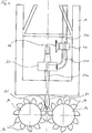
- the Fig. 1 shows an overall view of a trench cutter 10 according to the invention with a box-like Fräsrahmen 12, at the lower end of two pairs of cutting wheels 14 are arranged.
- the cutting wheels 14 are rotating about a not shown Drive motor rotatably driven about mutually parallel horizontal axes of rotation.
- detachable cutting teeth 16 are arranged in a known manner on plate-shaped brackets, which can be milled with which pending in the milling operation on the slot bottom soil material.
- the milling slot is filled with a supporting liquid, which in Fig. 1 not shown.
- the milled soil material is sucked together with surrounding supporting liquid as milling liquid via a centrally arranged between the cutting wheels 14 suction 24 a discharge device 20.
- the suction element 24 is connected via a lower discharge line 26a to a discharge pump 22 of the discharge device 20 arranged on the frame.
- the discharge pump 22 generates the suction pressure for sucking the milling fluid.
- the sucked milling fluid is then removed via the discharge pump 22 further upwards via an upper discharge line 26c from the milling slot.
- the milling fluid can be prepared for days in a suitable facility, be de-enriched especially from milled soil material.
- the processed milling fluid can then be returned to the slot as support fluid.
- a holding device 18 is arranged at the upper end of the milling frame 20, at the upper end of the milling frame 20, a holding device 18 is arranged.
- the trench wall cutter 10 can be attached to a cable or a guide rod of a carrier device, not shown, and in particular thereby vertically moved.
- trench wall cutter 10 has, for example, a box-shaped milling frame 12, which is provided with lateral guide elements.
- the trench wall cutter 10 can lead itself in the slot.
- the milling frame 12 may also be formed compact and substantially without guide elements for contact guidance. The guide then takes place via an attached to the holding device 18 guide rod from outside the Frässchlitzes on the carrier device.
- a switching device 40 provided, with which in the illustrated embodiment, the trench wall cutter 10 can be switched from a milling operation in a rinsing operation for flushing the cutting wheels 14.
- the switching device 40 a control valve 42 between a central discharge line 26b and the upper discharge line 26c of the discharge device 20.
- the control valve 42 By means of the control valve 42, the upper discharge line 26c located above the control valve 42 is shut off and at the same time an intake opening 44 on the control valve 42 is released.
- the intake opening 44 is preferably located above the discharge pump 22 in an upper area of the milling frame 12 which is at a distance from the cutting wheels 14.
- the discharge pump 22 as an adjustable pump, also called Wegschwenkbare pump formed. Simultaneously with the actuation of the control valve 42, the discharge pump 22 is changed over in its conveying direction.
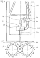
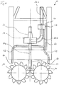
- the discharge pump 22 when opening the suction port 44, the discharge pump 22 from a milling operation, in which the discharge pump 22 promotes milling fluid from the cutting wheels 14 upwards, as clearly in Fig. 2 represented by arrows, in a rinsing operation according to Fig. 3 switched.
- the trench wall cutter 10 is raised, so that the cutting wheels 14 are spaced from the upcoming slot base.
- a flushing can be switched back by means of the control device in the milling operation, in which case then the cutter is lowered back to the slot base for milling further soil material.
- FIGS. 4 and 5 a second embodiment of a trench cutter 10 according to the invention is shown. It shows Fig. 4 the trench wall cutter 10 in the milling operation, in which the trench wall cutter 10 operates according to the first embodiment described above. Ground material removed by the cutting wheels 14 is sucked by the discharge device 20 with the discharge pump 22 via the suction element 24 and conveyed upwards.
- the conveying direction of the discharge pump 22 remains in the rinsing operation, which in Fig. 5 is shown schematically, unchanged.
- the switching device 40 has a switching valve 48.
- the switching valve 48 blocks the upper discharge line 26c of the discharge device 20 and connects the middle discharge line 26b with a purge line arrangement 60.
- the purge line arrangement 60 has one or more purge lines 62 which lead from the changeover valve 48 down to the cutting wheels 14.
- the flushing lines 62 terminate in nozzle-like flushing outlets 64, with which the milling fluid conveyed by the discharge pump 22 is led back again to the cutting wheels 14 in the area of the cutting teeth 16 for releasing adhering soil material.
- a simple discharge pump 22 can continue to be used.
- the discharge pump 22 according to the first embodiment according to the FIGS. 1 to 3 converted in their conveying direction.
- the discharge pump 22 is thus also designed as an adjustable or Wegschwenkbare pump.
- liquid is now flushed from an upper region of the slit or from the processing plant itself via the discharge pump 22 and the suction element 24 back in the direction of the cutting wheels 14.
- a second pump 30 is provided on the trimming frame 12.
- this second pump 30 can additionally convey, via a rinsing line arrangement 60 with a plurality of rinsing lines 62 and rinsing outlets 64, additionally liquid toward the cutting wheels 14 and free flow of adhering soil material.
- a flushing out takes place both from the direction of the suction element 24 and through additional flushing outlets 64 of the flushing line arrangement 60.
- FIGS. 7 and 8th A fourth embodiment of a trench wall cutter 10 according to the invention is in the FIGS. 7 and 8th shown.
- the trench wall cutter 10 is in accordance Fig. 7 in the milling operation, in which, similar to the embodiments described above, milled from the cutting wheels 14 soil material sucked together with liquid through the suction element 24 by a discharge pump 22 of a discharge device 20 and a lower, middle and upper discharge line 26a, b, c upwards is carried away.
- a second pump 30 is connected via a lower auxiliary line 28a and an adjusting valve 52 of a switching device 40 according to the invention.
- the additional line 28 is connected to a purge line 60 with flushing lines 62. In milling operation according to Fig. 7 However, there is no line connection between the additional line 28 and the Speller effetsan ist 60th
- the adjustment valve 52 connects the additional line 28 of the second pump 30 with the Spagit effetsan whatsoever 60.
- the second pump 30 which is designed as an adjustable pump, switched in its conveying direction by the switching device 40.
- the second pump 30 via the additional line 28 liquid from top to bottom in the Spagit effetsan whatsoever 60 lead, which leads to the cutting wheels 14.
- corresponding flushing outlets 64 at the ends of the flushing lines 62 an outside of the cutting wheels 14 can be targeted for flushing away adhering soil material.
Landscapes
- Engineering & Computer Science (AREA)
- Mining & Mineral Resources (AREA)
- Mechanical Engineering (AREA)
- Civil Engineering (AREA)
- General Engineering & Computer Science (AREA)
- Structural Engineering (AREA)
- Life Sciences & Earth Sciences (AREA)
- General Life Sciences & Earth Sciences (AREA)
- Paleontology (AREA)
- Road Repair (AREA)
- Structures Of Non-Positive Displacement Pumps (AREA)
- Earth Drilling (AREA)
Priority Applications (5)
| Application Number | Priority Date | Filing Date | Title |
|---|---|---|---|
| EP18167973.9A EP3556942B1 (fr) | 2018-04-18 | 2018-04-18 | Foreuse pour faire une mur de diaphragma et procedé pour faire une mur de diaphragma |
| US16/383,708 US11286637B2 (en) | 2018-04-18 | 2019-04-15 | Trench cutter and method for producing a cut trench in the soil |
| JP2019078628A JP6725722B2 (ja) | 2018-04-18 | 2019-04-17 | 土壌に掘削トレンチを形成するためのトレンチ・カッター及び方法 |
| KR1020190045178A KR102311859B1 (ko) | 2018-04-18 | 2019-04-18 | 토양에 컷 트렌치를 생성하기 위한 트렌치 커터와 방법 |
| CN201910312717.2A CN110387918B (zh) | 2018-04-18 | 2019-04-18 | 用于在土壤中产生切割沟槽的沟槽切割器和方法 |
Applications Claiming Priority (1)
| Application Number | Priority Date | Filing Date | Title |
|---|---|---|---|
| EP18167973.9A EP3556942B1 (fr) | 2018-04-18 | 2018-04-18 | Foreuse pour faire une mur de diaphragma et procedé pour faire une mur de diaphragma |
Publications (2)
| Publication Number | Publication Date |
|---|---|
| EP3556942A1 true EP3556942A1 (fr) | 2019-10-23 |
| EP3556942B1 EP3556942B1 (fr) | 2020-04-29 |
Family
ID=62025702
Family Applications (1)
| Application Number | Title | Priority Date | Filing Date |
|---|---|---|---|
| EP18167973.9A Active EP3556942B1 (fr) | 2018-04-18 | 2018-04-18 | Foreuse pour faire une mur de diaphragma et procedé pour faire une mur de diaphragma |
Country Status (5)
| Country | Link |
|---|---|
| US (1) | US11286637B2 (fr) |
| EP (1) | EP3556942B1 (fr) |
| JP (1) | JP6725722B2 (fr) |
| KR (1) | KR102311859B1 (fr) |
| CN (1) | CN110387918B (fr) |
Cited By (1)
| Publication number | Priority date | Publication date | Assignee | Title |
|---|---|---|---|---|
| CN111441410A (zh) * | 2020-04-17 | 2020-07-24 | 徐州徐工基础工程机械有限公司 | 一种双轮铣削搅拌机辅助冲洗装置 |
Families Citing this family (2)
| Publication number | Priority date | Publication date | Assignee | Title |
|---|---|---|---|---|
| EP4086390B1 (fr) | 2021-05-06 | 2024-04-03 | BAUER Maschinen GmbH | Engin de creusement et procédé de creuser une fente dans le sol |
| EP4286593A1 (fr) | 2022-05-30 | 2023-12-06 | BAUER Spezialtiefbau GmbH | Dispositif d'excavation et procede de creation d'un trou |
Citations (8)
| Publication number | Priority date | Publication date | Assignee | Title |
|---|---|---|---|---|
| EP0249555A1 (fr) * | 1986-06-11 | 1987-12-16 | SOLETANCHE Société Anonyme dite: | Motopompe pour engin de fraisage destiné à creuser des tranchées dans le sol |
| EP0253726A1 (fr) * | 1986-07-15 | 1988-01-20 | SOLETANCHE Société Anonyme dite: | Engin pour creuser des tranchées dans le sol à l'aide de fraises |
| DE4141629A1 (de) | 1991-12-17 | 1993-06-24 | Bauer Spezialtiefbau | Verfahren zur herstellung von dichtwaenden |
| EP0730064A1 (fr) | 1995-02-28 | 1996-09-04 | Compagnie Du Sol | Appareil destiné à creuser des tranchées dans le sol |
| EP1452645A1 (fr) | 2003-02-27 | 2004-09-01 | BAUER Maschinen GmbH | Procédé pour creuser des tranchées dans le sol et fraiseuse à rideau souterrain |
| WO2012007533A1 (fr) * | 2010-07-14 | 2012-01-19 | Damen Dredging Equipment Bv | Tête de coupe |
| EP2586962A1 (fr) * | 2011-10-24 | 2013-05-01 | Soilmec S.p.A. | Système d'évacuation de boue pour une machine à creuser des tranchées |
| EP2685007A1 (fr) | 2012-07-10 | 2014-01-15 | BAUER Maschinen GmbH | Cutting wheel for a slotted wall cutter |
Family Cites Families (19)
| Publication number | Priority date | Publication date | Assignee | Title |
|---|---|---|---|---|
| JPS495402B1 (fr) * | 1969-12-13 | 1974-02-07 | ||
| US4397106A (en) * | 1982-02-08 | 1983-08-09 | Ellicott Machine Corporation | Dredge bucket wheel structure |
| DE3424999C2 (de) * | 1984-07-06 | 1994-01-13 | Bauer Spezialtiefbau | Schlitzwandfräse |
| DE3602387C1 (de) * | 1986-01-28 | 1987-06-04 | Hochtief Ag Hoch Tiefbauten | Vorrichtung zum Einbringen eines im wesentlichen vertikalen Bodenschlitzes |
| JPH05280042A (ja) | 1992-03-31 | 1993-10-26 | Hazama Gumi Ltd | 連続地中壁における固化材の打設方法とその装置 |
| JP2591537Y2 (ja) * | 1992-09-29 | 1999-03-03 | 大成建設株式会社 | ドラムカッタの付着土除去装置 |
| JP2621762B2 (ja) * | 1993-06-01 | 1997-06-18 | 山▲さき▼建設株式会社 | 連続地中壁掘削機 |
| JPH10331188A (ja) * | 1997-05-30 | 1998-12-15 | Koken Boring Mach Co Ltd | 地中連続壁掘削機 |
| JP2001020317A (ja) * | 1999-07-02 | 2001-01-23 | Nippon Sharyo Seizo Kaisha Ltd | 地中掘削具 |
| FR2806111B1 (fr) * | 2000-03-13 | 2002-06-14 | Cie Du Sol | Appareil de forage en terrain dur |
| US6860042B2 (en) * | 2002-07-19 | 2005-03-01 | Walker-Dawson Interests, Inc. | Excavation system employing a jet pump |
| DE10308539B3 (de) * | 2003-02-27 | 2004-06-03 | Bauer Maschinen Gmbh | Fräsvorrichtung zum Fräsen von Schlitzen im Boden |
| ES2299779T3 (es) * | 2004-08-23 | 2008-06-01 | Bauer Maschinen Gmbh | Metodo y dispositivo de fresado de muro pantalla para la produccion de un muro pantalla en el suelo. |
| FR2904339B1 (fr) * | 2006-07-28 | 2011-03-04 | Cie Du Sol | Tete de coupe pour une machine d'excavation |
| ITTO20070241A1 (it) * | 2007-04-05 | 2008-10-06 | Soilmec Spa | Pompa per idrofresa. |
| ITUD20120148A1 (it) * | 2012-08-30 | 2014-03-01 | Casagrande Spa | Attrezzatura di scavo |
| KR101664366B1 (ko) | 2016-02-03 | 2016-10-24 | (주)케이씨이피중공업 | 콘크리트 펌프카의 콘크리트 회수장치 및 방법 |
| CN106223381A (zh) * | 2016-08-31 | 2016-12-14 | 徐州徐工基础工程机械有限公司 | 一种一机两用型地下连续墙施工设备 |
| JP6821244B2 (ja) | 2016-09-30 | 2021-01-27 | 日本車輌製造株式会社 | 地盤改良機 |
-
2018
- 2018-04-18 EP EP18167973.9A patent/EP3556942B1/fr active Active
-
2019
- 2019-04-15 US US16/383,708 patent/US11286637B2/en active Active
- 2019-04-17 JP JP2019078628A patent/JP6725722B2/ja active Active
- 2019-04-18 CN CN201910312717.2A patent/CN110387918B/zh active Active
- 2019-04-18 KR KR1020190045178A patent/KR102311859B1/ko active IP Right Grant
Patent Citations (8)
| Publication number | Priority date | Publication date | Assignee | Title |
|---|---|---|---|---|
| EP0249555A1 (fr) * | 1986-06-11 | 1987-12-16 | SOLETANCHE Société Anonyme dite: | Motopompe pour engin de fraisage destiné à creuser des tranchées dans le sol |
| EP0253726A1 (fr) * | 1986-07-15 | 1988-01-20 | SOLETANCHE Société Anonyme dite: | Engin pour creuser des tranchées dans le sol à l'aide de fraises |
| DE4141629A1 (de) | 1991-12-17 | 1993-06-24 | Bauer Spezialtiefbau | Verfahren zur herstellung von dichtwaenden |
| EP0730064A1 (fr) | 1995-02-28 | 1996-09-04 | Compagnie Du Sol | Appareil destiné à creuser des tranchées dans le sol |
| EP1452645A1 (fr) | 2003-02-27 | 2004-09-01 | BAUER Maschinen GmbH | Procédé pour creuser des tranchées dans le sol et fraiseuse à rideau souterrain |
| WO2012007533A1 (fr) * | 2010-07-14 | 2012-01-19 | Damen Dredging Equipment Bv | Tête de coupe |
| EP2586962A1 (fr) * | 2011-10-24 | 2013-05-01 | Soilmec S.p.A. | Système d'évacuation de boue pour une machine à creuser des tranchées |
| EP2685007A1 (fr) | 2012-07-10 | 2014-01-15 | BAUER Maschinen GmbH | Cutting wheel for a slotted wall cutter |
Cited By (1)
| Publication number | Priority date | Publication date | Assignee | Title |
|---|---|---|---|---|
| CN111441410A (zh) * | 2020-04-17 | 2020-07-24 | 徐州徐工基础工程机械有限公司 | 一种双轮铣削搅拌机辅助冲洗装置 |
Also Published As
| Publication number | Publication date |
|---|---|
| US20190323200A1 (en) | 2019-10-24 |
| KR102311859B1 (ko) | 2021-10-12 |
| JP6725722B2 (ja) | 2020-07-22 |
| CN110387918A (zh) | 2019-10-29 |
| EP3556942B1 (fr) | 2020-04-29 |
| CN110387918B (zh) | 2022-03-11 |
| JP2019190268A (ja) | 2019-10-31 |
| US11286637B2 (en) | 2022-03-29 |
| KR20190121706A (ko) | 2019-10-28 |
Similar Documents
| Publication | Publication Date | Title |
|---|---|---|
| DE10308538C5 (de) | Verfahren zum Herstellen einer Schlitzwand im Boden, Schlitzwandfräse und Schlitzwandfräsvorrichtung | |
| EP3543408B1 (fr) | Engin de fraisage pour creuser des tranchées dans le sol et procédé de creusage des tranchées dans le sol | |
| DE1902138A1 (de) | Verfahren und Vorrichtung zur Herstellung von Untergrundbauten im Erdkoerper,insbesondere von wasserdichten Dichtungsschuerzen | |
| EP3556942B1 (fr) | Foreuse pour faire une mur de diaphragma et procedé pour faire une mur de diaphragma | |
| DE2335893C3 (de) | Vorrichtung zum Erzeugen von pulsierenden Flüssigkeitsstrahlen hoher Geschwindigkeit und hoher Impulsfrequenz | |
| EP3296468B1 (fr) | Procédé et fraiseuse à rideau souterrain pour réaliser une tranchée dans le sol | |
| EP0450170A2 (fr) | Dispositif de régénération de puits | |
| EP1630298A1 (fr) | Procédée de fabriquer une mure en béton sur sol | |
| DE2810386B1 (de) | Vorrichtung zum Vortrieb von Graeben | |
| EP0106308A2 (fr) | Dispositif pour le travail du sol en agriculture | |
| DE3239756A1 (de) | Verfahren und vorrichtung zur reinigung von sielrohren | |
| DE3726472C2 (fr) | ||
| EP2182115A1 (fr) | Dispositif de nivellement de ballast | |
| DE19642711A1 (de) | Vorrichtung und Verfahren zur kontrollierten Herstellung von Pfählen oder Pfahlwänden im Boden | |
| EP2666911B1 (fr) | Procédé de fabrication d'une paroi en mortier fixée dans le sol | |
| DE19859666C2 (de) | Vorrichtung zum Fördern von Bodenmaterial aus einem mit Flüssigkeit gefüllten Bohrloch | |
| DE10308330B4 (de) | Injektionsvorrichtung | |
| DE2608665A1 (de) | Foerderkopf fuer einen druckluft- bagger | |
| DE10150278B4 (de) | Verfahren und Vorrichtung zum Bodenstabilisieren | |
| DE1634781A1 (de) | Erdbewegungsgeraet fuer das Zuschuetten von Graeben | |
| EP4286593A1 (fr) | Dispositif d'excavation et procede de creation d'un trou | |
| DE19536778C1 (de) | Maschine zum Einbauen einer im wesentlichen senkrechten Dichtung in eine Bodenformation | |
| EP4086390A1 (fr) | Engin de creusement et procédé de creuser une fente dans le sol | |
| DE10111522A1 (de) | Verfahren und Vorrichtung zum Bohren eines Pflanzlochs in Erdboden | |
| CH715857B1 (de) | Vorrichtung und Verfahren für den Abtrag von Bodenbelägen. |
Legal Events
| Date | Code | Title | Description |
|---|---|---|---|
| PUAI | Public reference made under article 153(3) epc to a published international application that has entered the european phase |
Free format text: ORIGINAL CODE: 0009012 |
|
| STAA | Information on the status of an ep patent application or granted ep patent |
Free format text: STATUS: REQUEST FOR EXAMINATION WAS MADE |
|
| 17P | Request for examination filed |
Effective date: 20180827 |
|
| AK | Designated contracting states |
Kind code of ref document: A1 Designated state(s): AL AT BE BG CH CY CZ DE DK EE ES FI FR GB GR HR HU IE IS IT LI LT LU LV MC MK MT NL NO PL PT RO RS SE SI SK SM TR |
|
| AX | Request for extension of the european patent |
Extension state: BA ME |
|
| GRAP | Despatch of communication of intention to grant a patent |
Free format text: ORIGINAL CODE: EPIDOSNIGR1 |
|
| STAA | Information on the status of an ep patent application or granted ep patent |
Free format text: STATUS: GRANT OF PATENT IS INTENDED |
|
| INTG | Intention to grant announced |
Effective date: 20191219 |
|
| GRAS | Grant fee paid |
Free format text: ORIGINAL CODE: EPIDOSNIGR3 |
|
| GRAA | (expected) grant |
Free format text: ORIGINAL CODE: 0009210 |
|
| STAA | Information on the status of an ep patent application or granted ep patent |
Free format text: STATUS: THE PATENT HAS BEEN GRANTED |
|
| AK | Designated contracting states |
Kind code of ref document: B1 Designated state(s): AL AT BE BG CH CY CZ DE DK EE ES FI FR GB GR HR HU IE IS IT LI LT LU LV MC MK MT NL NO PL PT RO RS SE SI SK SM TR |
|
| REG | Reference to a national code |
Ref country code: GB Ref legal event code: FG4D Free format text: NOT ENGLISH |
|
| REG | Reference to a national code |
Ref country code: CH Ref legal event code: EP |
|
| REG | Reference to a national code |
Ref country code: AT Ref legal event code: REF Ref document number: 1263468 Country of ref document: AT Kind code of ref document: T Effective date: 20200515 |
|
| REG | Reference to a national code |
Ref country code: DE Ref legal event code: R096 Ref document number: 502018001302 Country of ref document: DE |
|
| REG | Reference to a national code |
Ref country code: IE Ref legal event code: FG4D Free format text: LANGUAGE OF EP DOCUMENT: GERMAN |
|
| REG | Reference to a national code |
Ref country code: NL Ref legal event code: MP Effective date: 20200429 |
|
| REG | Reference to a national code |
Ref country code: LT Ref legal event code: MG4D |
|
| PG25 | Lapsed in a contracting state [announced via postgrant information from national office to epo] |
Ref country code: NO Free format text: LAPSE BECAUSE OF FAILURE TO SUBMIT A TRANSLATION OF THE DESCRIPTION OR TO PAY THE FEE WITHIN THE PRESCRIBED TIME-LIMIT Effective date: 20200729 Ref country code: LT Free format text: LAPSE BECAUSE OF FAILURE TO SUBMIT A TRANSLATION OF THE DESCRIPTION OR TO PAY THE FEE WITHIN THE PRESCRIBED TIME-LIMIT Effective date: 20200429 Ref country code: FI Free format text: LAPSE BECAUSE OF FAILURE TO SUBMIT A TRANSLATION OF THE DESCRIPTION OR TO PAY THE FEE WITHIN THE PRESCRIBED TIME-LIMIT Effective date: 20200429 Ref country code: IS Free format text: LAPSE BECAUSE OF FAILURE TO SUBMIT A TRANSLATION OF THE DESCRIPTION OR TO PAY THE FEE WITHIN THE PRESCRIBED TIME-LIMIT Effective date: 20200829 Ref country code: SE Free format text: LAPSE BECAUSE OF FAILURE TO SUBMIT A TRANSLATION OF THE DESCRIPTION OR TO PAY THE FEE WITHIN THE PRESCRIBED TIME-LIMIT Effective date: 20200429 Ref country code: GR Free format text: LAPSE BECAUSE OF FAILURE TO SUBMIT A TRANSLATION OF THE DESCRIPTION OR TO PAY THE FEE WITHIN THE PRESCRIBED TIME-LIMIT Effective date: 20200730 Ref country code: PT Free format text: LAPSE BECAUSE OF FAILURE TO SUBMIT A TRANSLATION OF THE DESCRIPTION OR TO PAY THE FEE WITHIN THE PRESCRIBED TIME-LIMIT Effective date: 20200831 |
|
| PG25 | Lapsed in a contracting state [announced via postgrant information from national office to epo] |
Ref country code: RS Free format text: LAPSE BECAUSE OF FAILURE TO SUBMIT A TRANSLATION OF THE DESCRIPTION OR TO PAY THE FEE WITHIN THE PRESCRIBED TIME-LIMIT Effective date: 20200429 Ref country code: LV Free format text: LAPSE BECAUSE OF FAILURE TO SUBMIT A TRANSLATION OF THE DESCRIPTION OR TO PAY THE FEE WITHIN THE PRESCRIBED TIME-LIMIT Effective date: 20200429 Ref country code: HR Free format text: LAPSE BECAUSE OF FAILURE TO SUBMIT A TRANSLATION OF THE DESCRIPTION OR TO PAY THE FEE WITHIN THE PRESCRIBED TIME-LIMIT Effective date: 20200429 Ref country code: BG Free format text: LAPSE BECAUSE OF FAILURE TO SUBMIT A TRANSLATION OF THE DESCRIPTION OR TO PAY THE FEE WITHIN THE PRESCRIBED TIME-LIMIT Effective date: 20200729 |
|
| PG25 | Lapsed in a contracting state [announced via postgrant information from national office to epo] |
Ref country code: NL Free format text: LAPSE BECAUSE OF FAILURE TO SUBMIT A TRANSLATION OF THE DESCRIPTION OR TO PAY THE FEE WITHIN THE PRESCRIBED TIME-LIMIT Effective date: 20200429 Ref country code: AL Free format text: LAPSE BECAUSE OF FAILURE TO SUBMIT A TRANSLATION OF THE DESCRIPTION OR TO PAY THE FEE WITHIN THE PRESCRIBED TIME-LIMIT Effective date: 20200429 |
|
| PG25 | Lapsed in a contracting state [announced via postgrant information from national office to epo] |
Ref country code: ES Free format text: LAPSE BECAUSE OF FAILURE TO SUBMIT A TRANSLATION OF THE DESCRIPTION OR TO PAY THE FEE WITHIN THE PRESCRIBED TIME-LIMIT Effective date: 20200429 Ref country code: CZ Free format text: LAPSE BECAUSE OF FAILURE TO SUBMIT A TRANSLATION OF THE DESCRIPTION OR TO PAY THE FEE WITHIN THE PRESCRIBED TIME-LIMIT Effective date: 20200429 Ref country code: SM Free format text: LAPSE BECAUSE OF FAILURE TO SUBMIT A TRANSLATION OF THE DESCRIPTION OR TO PAY THE FEE WITHIN THE PRESCRIBED TIME-LIMIT Effective date: 20200429 Ref country code: RO Free format text: LAPSE BECAUSE OF FAILURE TO SUBMIT A TRANSLATION OF THE DESCRIPTION OR TO PAY THE FEE WITHIN THE PRESCRIBED TIME-LIMIT Effective date: 20200429 Ref country code: DK Free format text: LAPSE BECAUSE OF FAILURE TO SUBMIT A TRANSLATION OF THE DESCRIPTION OR TO PAY THE FEE WITHIN THE PRESCRIBED TIME-LIMIT Effective date: 20200429 Ref country code: EE Free format text: LAPSE BECAUSE OF FAILURE TO SUBMIT A TRANSLATION OF THE DESCRIPTION OR TO PAY THE FEE WITHIN THE PRESCRIBED TIME-LIMIT Effective date: 20200429 |
|
| REG | Reference to a national code |
Ref country code: DE Ref legal event code: R097 Ref document number: 502018001302 Country of ref document: DE |
|
| PG25 | Lapsed in a contracting state [announced via postgrant information from national office to epo] |
Ref country code: PL Free format text: LAPSE BECAUSE OF FAILURE TO SUBMIT A TRANSLATION OF THE DESCRIPTION OR TO PAY THE FEE WITHIN THE PRESCRIBED TIME-LIMIT Effective date: 20200429 Ref country code: SK Free format text: LAPSE BECAUSE OF FAILURE TO SUBMIT A TRANSLATION OF THE DESCRIPTION OR TO PAY THE FEE WITHIN THE PRESCRIBED TIME-LIMIT Effective date: 20200429 |
|
| PLBE | No opposition filed within time limit |
Free format text: ORIGINAL CODE: 0009261 |
|
| STAA | Information on the status of an ep patent application or granted ep patent |
Free format text: STATUS: NO OPPOSITION FILED WITHIN TIME LIMIT |
|
| 26N | No opposition filed |
Effective date: 20210201 |
|
| PG25 | Lapsed in a contracting state [announced via postgrant information from national office to epo] |
Ref country code: MC Free format text: LAPSE BECAUSE OF FAILURE TO SUBMIT A TRANSLATION OF THE DESCRIPTION OR TO PAY THE FEE WITHIN THE PRESCRIBED TIME-LIMIT Effective date: 20200429 |
|
| PG25 | Lapsed in a contracting state [announced via postgrant information from national office to epo] |
Ref country code: LU Free format text: LAPSE BECAUSE OF NON-PAYMENT OF DUE FEES Effective date: 20210418 |
|
| REG | Reference to a national code |
Ref country code: BE Ref legal event code: MM Effective date: 20210430 |
|
| PG25 | Lapsed in a contracting state [announced via postgrant information from national office to epo] |
Ref country code: LI Free format text: LAPSE BECAUSE OF NON-PAYMENT OF DUE FEES Effective date: 20210430 Ref country code: CH Free format text: LAPSE BECAUSE OF NON-PAYMENT OF DUE FEES Effective date: 20210430 |
|
| PG25 | Lapsed in a contracting state [announced via postgrant information from national office to epo] |
Ref country code: IE Free format text: LAPSE BECAUSE OF NON-PAYMENT OF DUE FEES Effective date: 20210418 |
|
| PG25 | Lapsed in a contracting state [announced via postgrant information from national office to epo] |
Ref country code: BE Free format text: LAPSE BECAUSE OF NON-PAYMENT OF DUE FEES Effective date: 20210430 |
|
| P01 | Opt-out of the competence of the unified patent court (upc) registered |
Effective date: 20230510 |
|
| PG25 | Lapsed in a contracting state [announced via postgrant information from national office to epo] |
Ref country code: CY Free format text: LAPSE BECAUSE OF FAILURE TO SUBMIT A TRANSLATION OF THE DESCRIPTION OR TO PAY THE FEE WITHIN THE PRESCRIBED TIME-LIMIT Effective date: 20200429 |
|
| PG25 | Lapsed in a contracting state [announced via postgrant information from national office to epo] |
Ref country code: HU Free format text: LAPSE BECAUSE OF FAILURE TO SUBMIT A TRANSLATION OF THE DESCRIPTION OR TO PAY THE FEE WITHIN THE PRESCRIBED TIME-LIMIT; INVALID AB INITIO Effective date: 20180418 |
|
| PGFP | Annual fee paid to national office [announced via postgrant information from national office to epo] |
Ref country code: IT Payment date: 20230403 Year of fee payment: 6 Ref country code: FR Payment date: 20230403 Year of fee payment: 6 Ref country code: DE Payment date: 20230411 Year of fee payment: 6 |
|
| PGFP | Annual fee paid to national office [announced via postgrant information from national office to epo] |
Ref country code: AT Payment date: 20230404 Year of fee payment: 6 |
|
| PG25 | Lapsed in a contracting state [announced via postgrant information from national office to epo] |
Ref country code: SI Free format text: LAPSE BECAUSE OF FAILURE TO SUBMIT A TRANSLATION OF THE DESCRIPTION OR TO PAY THE FEE WITHIN THE PRESCRIBED TIME-LIMIT Effective date: 20200429 |
|
| PGFP | Annual fee paid to national office [announced via postgrant information from national office to epo] |
Ref country code: GB Payment date: 20230404 Year of fee payment: 6 |
|
| PG25 | Lapsed in a contracting state [announced via postgrant information from national office to epo] |
Ref country code: MK Free format text: LAPSE BECAUSE OF FAILURE TO SUBMIT A TRANSLATION OF THE DESCRIPTION OR TO PAY THE FEE WITHIN THE PRESCRIBED TIME-LIMIT Effective date: 20200429 |