EP3556938B1 - Rail pour être monté élastiquement - Google Patents
Rail pour être monté élastiquement Download PDFInfo
- Publication number
- EP3556938B1 EP3556938B1 EP19168409.1A EP19168409A EP3556938B1 EP 3556938 B1 EP3556938 B1 EP 3556938B1 EP 19168409 A EP19168409 A EP 19168409A EP 3556938 B1 EP3556938 B1 EP 3556938B1
- Authority
- EP
- European Patent Office
- Prior art keywords
- rail
- joint
- filling element
- surround
- rail head
- Prior art date
- Legal status (The legal status is an assumption and is not a legal conclusion. Google has not performed a legal analysis and makes no representation as to the accuracy of the status listed.)
- Active
Links
Images




Classifications
-
- E—FIXED CONSTRUCTIONS
- E01—CONSTRUCTION OF ROADS, RAILWAYS, OR BRIDGES
- E01B—PERMANENT WAY; PERMANENT-WAY TOOLS; MACHINES FOR MAKING RAILWAYS OF ALL KINDS
- E01B21/00—Track superstructure adapted for tramways in paved streets
-
- E—FIXED CONSTRUCTIONS
- E01—CONSTRUCTION OF ROADS, RAILWAYS, OR BRIDGES
- E01C—CONSTRUCTION OF, OR SURFACES FOR, ROADS, SPORTS GROUNDS, OR THE LIKE; MACHINES OR AUXILIARY TOOLS FOR CONSTRUCTION OR REPAIR
- E01C9/00—Special pavings; Pavings for special parts of roads or airfields
- E01C9/06—Pavings adjacent tramways rails ; Pavings comprising railway tracks
Definitions
- the invention relates to a rail to be elastically supported, which has a rail head with a running surface for the vehicle wheels, a rail foot and a rail web connecting these, in particular a grooved rail which is intended to be replaced by a possibly multilayered surrounding that forms an embedding of the rail.
- Substructure the surface of which is in the height range of the running surface, to be surrounded at least on one side, with a joint between the embedding and the side surface of the rail head which is to be filled with a joint filling element.
- the invention also relates to a method for the elastic laying of a rail in a track bed.
- the rail treads for the vehicle wheels are almost flush with the road surface.
- the rails are elastically mounted to reduce vibrations and to provide soundproofing for both the vehicle and the environment. Therefore, in addition to thermal movements, the rail head is deflected not only in the vertical but also in the horizontal direction when the vehicle travels over it.
- the EP 2 960 370 A1 shows a "shoe" for a Vignol rail in the form of a plastic cover with air chambers that envelops the rail except for the running surfaces.
- An elastic intermediate layer is inserted into the sleeve under the rail foot.
- a connection to a road body or the like. is not scheduled.
- the casing completely surrounding the rail is also provided for the important electrical insulation of the rail from the ground.
- the EP 2 019 168 B1 describes a similar cover for a grooved rail.
- the shell ends in front of the upper part of the rail head sides.
- the area of the casing adjoining this, resting on the lower part of the rail head of the grooved rail, is connected to the rail by an adhesive strip.
- the EP 1 206 599 B1 describes profiles to be attached to the side of a grooved rail, which protrude on the rail head sides up to close to the running surface. This is intended to shield the rail from the road structure that comes close to the rail.
- DE 10 2016 114 172 A1 shows profiles to be attached to the side of a grooved rail, which leave the sides of the rail head blank for the most part.
- An insulating layer sprayed onto the rail extends right up to the running surface.
- the joint to the body is filled with a joint filler as described above.
- the EP 1 331 310 A2 shows a grooved rail, during the assembly of which elastic plates are first glued to the underside of the rail feet. Left and right bearing parts are glued to the rail web, with an elastic layer protruding above and below the support parts.
- the construction pit is poured up to the specified height with concrete 11, which laterally adjoins the elastic layers and penetrates into the part of a mounting grid protruding over the side walls of the elastic layers, so that when the concrete hardens an anchoring of the bearing parts and thus the Rail is done in concrete.
- An asphalt layer forming the road surface is applied to this concrete layer, a joint to the rail head or to the elastic intermediate layer resting against it remains. This joint is then grouted with a bituminous grouting compound.
- Rails with joint fillers are also in EP 1 956 143 A1 , EP 1 219 749 A2 , WO 2018/010740 A1 , FR 2911154 A and DE 10 2014 114 172 A1 disclosed.
- One object of the invention is to create a permanent joint that is suitable for elastic rail mounting between the rail head and the adjacent remodeling with little installation effort at the construction site.
- a prefabricated joint filling element which consists of an elastic material, with an inside facing the rail head and an inside facing away from it Outside, an upper side and a lower side is formed, wherein the inner side is permanently adhered to the side surface of the rail head before the laying of the rail, an outer side opposite the inner side is designed to promote adhesion and an underside facing a rail foot is designed to prevent adhesion.
- the rail can therefore be provided beforehand, for example in a workshop and before being transported to the installation site, with a joint filling element on both sides of the rail head, which is firmly attached and is prepared on the outward-facing sides, after the elastic Attachment of the rail to the ground with a conversion material, i.e. concrete or asphalt, to be brought into engagement with adhesion.
- a conversion material i.e. concrete or asphalt
- an adhesive can be applied.
- the rail head sides unlike on the construction site, by cleaning, primers or the like. can be prepared for a particularly good hold.
- the material of the joint filling element preferably a slab-terminated polymer, itself as an adhesive on the rail head side.
- the silane-terminated polymers have a very high elasticity and recovery, but take longer to harden because they are moisture-hardening, which would be a problem on the construction site.
- a form-fitting connection between the joint filling element and the conversion for example an undercut, can be provided.
- This can be, for example, a fleece, the fibers of which protrude beyond the outside and, according to the invention, also the inside of the joint filling element and is introduced during the production of the joint filling element in such a way that it is embedded in the material of the joint filling element and the adhesive on the inside and / or on the outside the concrete slurry or the asphalt, so that a form-fitting, integrated connection is created that provides tensile elements as anchoring.
- adhesion-promoting elements or arrangements are understood to be understood here, which fix the positioning of adjacent elements or their surfaces to one another indirectly and / or directly, in particular by positively locking, non-positively or materially locking.
- anchoring measures are also useful, for example embedding fibers or a fabric, for example one or more fabric strips that protrude beyond the outside of the joint filling element. All of this creates a connection that is not only pressure-resistant, but also tensile-resistant, which takes into account the fact that the rail is laid out not only vertically but also horizontally during operation, whereby the joint filling element is supposed to absorb these movements as compression and expansion without it loosens from the rail head sides and / or the conversion (concrete or asphalt) and forms gaps into which water and dirt can penetrate, which can lead to the joint becoming completely detached.
- the joint filling element should not enter into any adhesive connection on its underside, mostly to a rail chamber filling element or the surrounding or substructure.
- a release agent can be used, either in the form of an applied or split release agent layer or by sprinkling on dry sand.
- the joint filling element can be provided with a pretensioning device which can be triggered after the conversion has been applied and which applies compressive stress between the conversion and the side of the rail head. This would prevent significant tensile stresses from acting on the connection points of the joint filling element during lateral movements if the prestressing is dimensioned such that the compressive prestressing predominates even with maximum deflection.
- devices can be introduced into the joint filling element during manufacture, for example buckling elements that are deflected transversely to the prestressing direction, i.e. in the vertical direction, i.e. in the direction of extension between the outside and inside of the joint filling element and, by acting on the joint filling element, for example by a blow or pressure on its upper side
- buckling elements that are deflected transversely to the prestressing direction, i.e. in the vertical direction, i.e. in the direction of extension between the outside and inside of the joint filling element and, by acting on the joint filling element, for example by a blow or pressure on its upper side
- buckling elements that are deflected transversely to the prestressing direction, i.e. in the vertical direction, i.e. in the direction of extension between the outside and inside of the joint filling element and, by acting on the joint filling element, for example by a blow or pressure on its upper side
- a snap element assume an elongated and
- a pre-tensioned U-shaped leaf spring is also possible, which is provided in a chamber, for example in a channel of the joint filling element and is held in its pre-tensioned position by a trigger which, in turn, acts on the upper side of the elastic joint filling element, the legs of the leaf spring releases.
- Another useful option is to create a chamber in the joint filling element, which is placed under negative pressure itself or, for example, by an inserted hose, whereby after the installation of the rail a tiny connection with the atmosphere is sufficient to create the hose and thus the chamber to expand and thus to pretension the joint filling element.
- joint filling element under compressive stress between its inner and outer sides after its production and to block it with an outer tensioning element, for example with an adhesive strip, which is removed after the rail has been laid.
- an outer tensioning element for example with an adhesive strip
- an internal tensioning element for example a kind of sewing, whereby the sewing threads can be destroyed by the action of heat.
- the invention creates a method for the elastic laying of a rail, in particular a rail according to the invention in a track bed, which has a rail head with a running surface for the vehicle wheels, a rail foot and a rail web connecting these, in which in a first step before the laying, for example in a Workshop or a manufacturing company, a prefabricated joint filling element is permanently attached to the sides of the rail head.
- the rail prepared in this way is elastically mounted on a substructure and the rail and, in particular, the joint filling element are enclosed in a tensile-resistant manner with a remodeling, that is, concrete or asphalt is poured around it.
- the material of the conversion can preferably enclose elements protruding beyond the outside of the joint filling element and embed them in the manner of tie rods in an adhesive manner.
- the invention thus creates a possibility of laying the rails in a short time and with little construction site effort, the rail with the conversion, in particular a conversion that is essentially the same as the rail, such as installation in a street, tightly and without the risk of a gap forming with penetration of Moisture and dirt is and remains connected even with use-related movements of the rail. It is also ensured that the rail remains electrically isolated from the conversion in this area, which is what it is.
- the rail can also be electrically insulated, as in the DE 10 2016 114 172 A1 the applicant is shown.
- the joint filling element In addition to the lateral, that is to say horizontal, movements of the rail during operation, the joint filling element also absorbs the vertical rail movements.
- the joint filling element and its adhesion are also ideally suited to elastically absorb shear movements and shear forces.
- the invention thus creates a rail and an elastic rail installation in which a prefabricated flexible joint filling element is provided during the preparation of the rail for the gap-free, tight closing of the joint that is created on both sides of the rail.
- Adhesion-promoting elements and measures are provided to create a pressure-resistant and tensile-resistant connection between the rail and the conversion, e.g. made of concrete or asphalt, which is only attached after the rail has been installed.
- a releasable expansion memory can be provided in the joint filling element, which creates and maintains a compressive prestress in the joint filling element between the conversion and the rail after the rail has been installed.
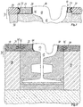
- the in Fig. 1 The section shown represents a rail vehicle (not shown), for example a tram, provided elastically in a track bed 11 grooved rail 12 Track channel side 16.
- the rail head 13 is connected to the rail foot 18 by a rail web 17. This is mounted on an elastic foot profile 19. This in turn rests on a base plate 25 which compensates for unevenness in the track bed foundation 26.
- a correspondingly shaped chamber filling element 21 is inserted that is supported on the rail foot on the one hand and on the undersides 22 of the rail head 13 on the other.
- the chamber filling elements end slightly below the rail head sides 23 in an essentially horizontal surface 24.
- a joint 50 is formed on both sides of the rail between the rail head sides 23 and a conversion 31 formed by in-situ concrete and / or the application of an asphalt layer after the rail 11 has been installed.
- joint filling elements 27 are adhered to the rail head sides 23 on both sides before the rail 11 is installed.
- These are prefabricated from a flexible plastic, in particular silane-terminated polymer in the form of a strip, for example as a continuously cast profile.
- Polyurethanes and polysulfites are also suitable. They have an upper side 33 which is essentially in one plane with the running surface 14 and the conversion (road) surface 30 of the conversion 31 or slightly below it, an underside 34 adjoining a chamber filling element 21 in the example shown, an inside adjoining the rail head side 35 and an outer side 36 which adjoins the enclosure 31.
- Fig. 2 and 3 it is shown that the connection to the rail head sides is made by an adhesive layer 28, to be precise already during the preparation of the rail in a workshop set up on it or a corresponding facility near the laying point. This ensures that the bonding takes place under the best conditions in terms of positioning, cleanliness, temperature control and preparation of the bonding surface on the rail 12 and joint filling element 27.
- the indicated adhesive layer 28 can be an adhesive that adheres well to the rail and to the material of the joint filling element 20, advantageously also made of the same material as the joint filling element itself.
- These examples also show a structuring of the outer sides 36 of the joint filling element 27 in such a way that a form fit (undercut) arises at least in the vertical direction by at Fig. 2 the outside 36 extends obliquely widening downwards and Fig. 3 the outside 36 has an inward curvature 37.
- the conversion 31 is created by pouring concrete or (see Figures 2 to 4) with an asphalt layer 39 applied to the concrete conversion sub-layer 38, which together form the conversion 31 , is made, a positively secured arrangement in the vertical direction (upwards).
- an adhesive layer 28 is also shown on the outside 36 of the joint filling element 27. Since work on the construction site, such as the application of adhesives etc., should be avoided as far as possible, an adhesive is only useful there, for example, if an adhesive layer 28 previously applied to the joint filling element can be activated by applying the conversion, e.g. if a Rebuilding 31 with an asphalt layer 39, when the liquid is applied, sufficient heat is available to activate an adhesive layer 28 consisting of hot-melt adhesive.
- the joint filling element was already provided with a fleece 41 on its inside and on the outside during manufacture, part of which, for example half of its thickness, is embedded in the material of the joint filling element 27.
- a fleece 41 on its inside and on the outside during manufacture, part of which, for example half of its thickness, is embedded in the material of the joint filling element 27.
- It is a high-density fleece made of plastic and compressed from several layers.
- a nonwoven is to be understood here as any material that is made up of fibers or threads in a regular or irregular, for example tangled, layer and leaves cavities lying undercuts free. It should have a certain thickness so that the materials between which it is supposed to provide adhesion can penetrate.
- the fleece 41 is filled approximately halfway with the material of the joint filling element 27 on its side facing the joint filling element 27.
- the fleece With a pressing process, the fleece can be shaped so that it can also be used as the formwork for the in Fig. 1
- the bevel 43 shown on the concrete structure 31 can form.
- the fleece 41 improves the adhesion to the sides of the rail head, in particular as far as the tensile strength of the adhesive connection is concerned. Due to the set absorbency of the fleece 41, it can absorb the silane-terminated polymer both during the production of the prefabricated joint filling element 27 and the concrete, ie the easily flowable portion of slurry or mortar contained therein, during the casting for the production of the conversion 31.
- the previously described adhesive layer 28 penetrates into the inner sides 35 of the joint filling elements protruding fibers, loops, loops or the like. of the fleece 41 and improves the adhesion even with a relatively smooth surface of the rail head sides. These can also have been treated with an adhesion promoter (primer) in preparation for the bond.
- the outer sides 36 of the joint filling elements 27 form the outer boundaries of the rail complex in the area close to the surface.
- the conversion is now carried out by grouting with the material provided, i.e. with in-situ concrete ( Fig. 1 ) or an asphalt layer 39 on a concrete conversion sub-layer ( Fig. 4 ).
- the initially flowable constituents of these materials i.e. concrete slurry and the largely liquid portion of the asphalt, which is usually reinforced with mineral materials, penetrate the elements protruding from the outside 36 and not embedded in the joint filling element 27, i.e. fibers, loops, loops or the like .
- a separating means 46 is provided between the horizontal surface 24 of the chamber filling element 21 (or other elements provided at this point) and the underside of the joint filling element 27. As the simplest implementation, this can also be sprinkled quartz sand. Oil paper or a geotextile fleece or a sprayed release agent can also be used.
- Fig. 4 shows that instead of the fleece on the outside 36 one or more fabrics 45, for example in the form of strips running along the rail, are embedded in the joint filling element, which are also embedded in the asphalt layer 39 belonging to the conversion 31 when the conversion is made. These can also be single fibers.
- a fleece 41 is provided as an adhesion promoter on the inside 35 of the joint filling element 27, as described.
- Fig. 5 shows a combination of the execution Fig. 2 with an embedded strip of fabric or fibers in the case of a concrete conversion 31.
- Fig. 6 shows an embodiment in which in addition to the fleece 41 also on the outside of the joint filling element 27, an element reinforcing the tensile strength, a fabric strip or fibers 45, are embedded in the lower part of the joint filling element 27, where the fleece 41 ends.
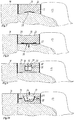
- the joint filling element 27 can particularly preferably be provided with a pretensioning device 51 that can be triggered after the conversion has been applied, so to speak an expansion storage device, which acts mainly in the horizontal direction. Examples are in the Figures 7 to 16 shown schematically.
- Figures 7 and 8 show schematically indicated an embodiment of the pretensioning device 51 in which one or more buckling elements 53 are provided in or on the joint filling element 27, for example as a layer of plastic platelets that are roof-shaped.
- the buckling elements 53 are pressed flat and also maintain this position.
- the material of the joint filling element is stretched somewhat in the middle area and forms a compressive prestress in the edge areas.
- Fig. 8 shows that the upper side 33 of the joint filling element 27 can thereby be somewhat concave, but this can be compensated for if this surface is made somewhat convex upwardly bulged.
- Figures 9 and 10 show an embodiment of the pretensioning device 51, in which a chamber 54 is provided in the joint filling element 27, which extends along the rail 11 and in which pretensioning devices 51 are arranged in U-shaped bent leaf springs 55 at a longitudinal distance from one another, which are tensioned by a tensioner or trigger 56 State ( Fig. 9 ) by engaging behind the bends 57 at the ends of the spring legs 58.
- the inverted T-shaped trigger will after installation by a pressure or blow on the top side 33 of the joint filling element 27 pressed down and releases the spring legs 58 so that they stretch the middle area of the joint filling element 27 and build up a total pressure bias in this, especially in the upper area.
- Figures 11 and 12 demonstrate an embodiment of the pretensioning device 51, in which components 47, 48 are provided in a chamber 54 provided centrally in the joint filling element 27 by a destructible wall 59.
- the chamber that contains one of the components for example, there can be a capsule or ampoule with a second component that enters into a chemical or physical reaction with the other, which leads to an increase in volume and an expansion to build up a compressive tension ( Fig. 12 ).
- the components can, for example, form a flexible, hardening plastic foam that permanently but flexibly enlarges the chamber. But there are also inorganic materials that can be irreversibly expanded by a second component, for example various clay materials or gypsum when water is added.
- a second component can also be dispensed with if the triggering reagent is water.
- the reaction could also be triggered by diffusing moisture.
- An expansion "with a time fuse" would then arise.
- the figures show that in this case the joint filling element is produced with a central constriction, that is to say in each case a concave upper and / or lower side, in order to obtain flat surfaces after the expansion.
- the desired compressive prestress can also be achieved by using a material for the joint filling element 27 which itself swells when absorbing moisture.
- This material is known as a swell seal. It is a 1-component, solvent-free and water-swellable flexible plastic material based on polyurethane. It is particularly advantageous that it has excellent adhesion properties on a wide variety of substrates. Here, it would only have to be ensured that the joint filling element 27 is shielded from water between production and use, which, however, is not a problem during production and storage in a company. If necessary, a tear-off cover could be provided.
- Figures 13 and 14 show an embodiment of the pretensioning device 51, which has a chamber 54 in which, possibly in a hose 60 located in the chamber 54, a negative pressure is generated after the production of the joint filling element 27, which causes the hose, the chamber and the central one to contract Part of the joint filling element is associated.
- the hose 60 can then be pierced at one end of the elongated joint filling element and thus enlarge the hose and also the chamber.
- FIGS 15 and 16 an embodiment of the pretensioning device 51, in which after the production of the joint filling element this is placed under lateral pressure, which is maintained by an inner tensioning element 61, for example by sewing between the inside and outside 35,36 of the filling element 27. This can be done with a thread 62, which melts easily, so that heating causes it to crack ( Fig. 16 ) and it releases the compressive stress stored in the joint filling element 27.
- Track bed 11 Grooved rail 12th Rail head 13th Tread 14th Track channel 15th Lane channel side 16 Rail web 17th Rail foot 18th Foot profile 19th Rail chamber 20th Chamber filling element 21 bottom 22nd Rail head side 23 horizontal plane 24 Base plate 25th Track bed foundation 26th Joint filling elements 27 Adhesive layer 28 Remodeling surface 30th modification 31 Top 33 bottom 34 inside 35 Outside 36 Inward rounding 37 Concrete conversion sub-layer 38 Asphalt layer 39 Adhesive layer 40 fleece 41 chamfer 43 tissue 45 Release agent 46 Gap 50 Pretensioning device 51 Buckling element 53 chamber 54 Leaf spring 55 trigger 56 Turns 57 Spring legs 58 Wall 59 hose 60 Clamping element 61 thread 62
Landscapes
- Engineering & Computer Science (AREA)
- Architecture (AREA)
- Civil Engineering (AREA)
- Structural Engineering (AREA)
- Road Paving Structures (AREA)
- Bridges Or Land Bridges (AREA)
Claims (14)
- Rail à poser de façon élastique (12) avec un élément de remplissage de joint (27), qui comporte un champignon de rail (13) avec une surface de roulement pour les roues de véhicule,un patin de rail (15) etune âme de rail (16) reliant ceux-cien particulier un rail encastré à gorge,qui est déterminé pour être entouré au moins d'un côté par un élément de réfection (31) multicouche en option, formant un encastrement du rail, dont la surface (30) se situe dans la zone haute de la surface de roulement (14), sachant qu'entre l'encastrement et une surface latérale (23) du champignon de rail (13), il y a un joint (50), qui doit être rempli d'un élément de remplissage de joint (27)sachant quel'élément de remplissage de joint (27) est préfabriqué et est composé d'un matériau élastique est constitué d'une face intérieure (35) tournée vers le champignon de rail (13) et und'une face extérieure (36) opposée au champignon de rail (13),d'une face supérieure (33) etd'une face inférieure (34) , sachant que la face intérieure est appliquée de façon durablement adhérente à la surface latérale (23) du champignon de rail (13) avant la pose du rail (12),la face extérieure (36) à l'élément de réfection (31) est constituée de façon favorisant l'adhérence et la face inférieure (34) de façon antiadhésive, caractérisé en ce quedes éléments favorisant l'adhérence sont intégrés dans le matériau de l'élément de remplissage de joint (27), qui comportent un matériau non-tissé (41) qui est intégré sur la face intérieure (35) dans une couche adhésive (28) à la surface latérale (23) du champignon de rail (13).
- Rail selon la revendication 1, caractérisé en ce que la face extérieure (36) de l'élément de remplissage de joint (27) a une structure qui forme avec l'élément de réfection (31) au moins en partie une liaison par conformité de forme.
- Rail selon l'une quelconque des revendications précédentes, caractérisé en ce que la propriété adhésive de la face extérieure (36) est prévue au moins en complément par une couche adhésive (28).
- Rail selon la revendication 1 ou 2, caractérisé en ce que les éléments favorisant l'adhérence comportent un matériau non-tissé (41), dont les fibres font saillie par la face extérieure (36) et pour une réception de bonne adhérence dans le matériau de l'élément de réfection (31),ou un tissu (45) dépassant de la face extérieure (36) pour une réception de bonne adhérence dans le matériau de la réfection (31),ou des fibres faisant saillie par la face extérieure (36) pour une réception de bonne adhérence dans le matériau de l'élément de réfection (31).
- Rail selon l'une quelconque des revendications précédentes, caractérisé en ce que l'élément de remplissage de joint (27) constitue une liaison élastique par compression et traction entre la surface latérale (23) du champignon de rail (13) et l'élément de réfection (31).
- Rail selon l'une quelconque des revendications précédentes, caractérisé en ce que la face inférieure (34) de l'élément de remplissage de joint (27) est constituée pour le raccordement antiadhésif au moyen d'un agent de séparation (46) à un élément de remplissage de chambre (21) à insérer dans une chambre de rail (20) formée entre le champignon de rail (13), l'âme de rail (17) et le patin de rail (18).
- Rail selon l'une quelconque des revendications précédentes, caractérisé en ce que l'élément de remplissage de joint (27) est doté d'un système de précontrainte (51) déclenchable après l'application de l'élément de réfection (31), qui applique une précontrainte par compression entre l'élément de réfection (31) et le côté du champignon de rail (23).
- Rail selon la revendication 7, caractérisé en ce que le dispositif de précontrainte déclenchable (51) comporte une des caractéristiques suivantes :l'élément de remplissage de joint (27) comporte au moins un des éléments pliants (23) dotés d'une orientation dirigée transversalement à la direction de précontrainte, qui doivent être mis dans une forme étendue par effet sur l'élément de remplissage de joint (27), ouun ressort (55) précontraint est introduit dans l'élément de remplissage de joint (27), en particulier un ressort à lames plié, qui est maintenu tendu par un déclencheur (56) jusqu'à ce qu'en agissant extérieurement sur l'élément de remplissage de joint (27), le déclencheur soit actionné pour libérer la tension de ressort, oul'élément de remplissage de joint (27) contient une chambre (54), qui est remplie d'un matériau se dilatant de façon irréversible par application de chaleur.
- Rail selon la revendication 6 ou 7, caractérisé en ce que le dispositif de précontrainte déclenchable (51) comporte une des caractéristiques suivantes :l'élément de remplissage de joint (27) contient une chambre (54), qui contient deux composants séparés initialement l'un de l'autre, qui sont mis en contact l'un avec l'autre par action mécanique par dilatation,oul'élément de remplissage de joint (27) contient une inclusion d'un matériau, qui augmente son volume par diffusion d'humidité dans l'élément de remplissage de joint, oul'élément de remplissage de joint (27) contient une chambre (54, 60), qui se trouve sous dépression atmosphérique et qui se dilate après création d'une entrée d'air.
- Rail selon l'une quelconque des revendications 6 à 9, caractérisé en ce que le dispositif de précontrainte déclenchable (51) comporte une des caractéristiques suivantes :l'élément de remplissage de joint (27) est fixé sous contrainte de compression, qui est bloquée par un élément de tension extérieur (61), qui doit être enlevé, oul'élément de remplissage de joint est fixé sous une contrainte de compression, qui est bloquée par un élément de tension intérieur (61, 62), qui peut être détruit par un effet thermique.
- Procédé pour la pose élastique d'un rail (12) avec élément de remplissage de joint (27) dans une couche de forme (11), qui comporte un champignon de rail (13) avec une surface de roulement pour les roues de véhicule, un patin de rail (18) et une âme de rail (17) reliant ceux-ci, en particulier un rail encastré à gorge, sachant que l'élément de remplissage de joint (27) est préfabriqué et est composé d'un matériau élastique, est constitué d'une face intérieure (35) tournée vers le champignon de rail (13) et d'une face extérieure (36) opposée au champignon de rail (13), une face supérieure (33) et
une face inférieure (34), avec les étapes de travail suivantes :application élastique à une infrastructure (26) du rail (12) muni au moins d'un côté de l'élément de remplissage de joint (27) appliqué de façon adhérente latéralement sur le champignon de rail (13) avant la pose,coulée de l'élément de réfection (31) sur la face extérieure (36) de l'élément de remplissage de joint (27) tout près par liaison par adhérence entre ceux-ci, caractérisé en ce quedes éléments favorisant l'adhérence sont incorporés dans le matériau de l'élément de remplissage de joint (27), qui comportent un matériau non-tissé (41), qui est incorporé à la face intérieure dans une couche adhésive (28) à la surface latérale (23) du champignon de rail (13). - Procédé selon la revendication 11, caractérisé en ce que la liaison par adhérence comprend une inclusion d'éléments ressortant par la face extérieure de l'élément de remplissage de joint (27) dans l'élément de réfection (31).
- Procédé selon la revendication 11 ou 12, caractérisé en ce qu'après la mise en place de l'élément de réfection (31) sur le rail par effet sur l'élément de remplissage de joint (27), un dispositif de précontrainte (51) prévu pour l'élément de remplissage de joint (27) est déclenché pour la formation d'une précontrainte par compression dans l'élément de remplissage de joint (27) entre le côté du champignon de rail (23) et l'élément de réfection (31).
- Procédé selon la revendication 13, caractérisé en ce que l'action sur l'élément de remplissage de joint (27) comprend une des étapes de travail suivantes :action mécanique sur la face supérieure (33) de l'élément de remplissage de joint (27) par compression ou percussion, ouaction thermique sur l'élément de remplissage de joint (27), oucréation d'une liaison d'une chambre (54, 60) se trouvant dans l'élément de remplissage de joint (27) avec l'atmosphère, ouenlèvement d'un dispositif bloquant une précontrainte de l'élément de remplissage de joint (27), oulibération de la surface supérieure de l'élément de remplissage de joint (27) pour humidité.
Priority Applications (1)
| Application Number | Priority Date | Filing Date | Title |
|---|---|---|---|
| PL19168409T PL3556938T3 (pl) | 2018-04-18 | 2019-04-10 | Szyna przystosowana do elastycznego układania |
Applications Claiming Priority (1)
| Application Number | Priority Date | Filing Date | Title |
|---|---|---|---|
| DE102018109255.5A DE102018109255A1 (de) | 2018-04-18 | 2018-04-18 | Elastisch zu lagernde Schiene |
Publications (2)
| Publication Number | Publication Date |
|---|---|
| EP3556938A1 EP3556938A1 (fr) | 2019-10-23 |
| EP3556938B1 true EP3556938B1 (fr) | 2021-10-13 |
Family
ID=66105055
Family Applications (1)
| Application Number | Title | Priority Date | Filing Date |
|---|---|---|---|
| EP19168409.1A Active EP3556938B1 (fr) | 2018-04-18 | 2019-04-10 | Rail pour être monté élastiquement |
Country Status (5)
| Country | Link |
|---|---|
| EP (1) | EP3556938B1 (fr) |
| DE (1) | DE102018109255A1 (fr) |
| DK (1) | DK3556938T3 (fr) |
| ES (1) | ES2902939T3 (fr) |
| PL (1) | PL3556938T3 (fr) |
Families Citing this family (1)
| Publication number | Priority date | Publication date | Assignee | Title |
|---|---|---|---|---|
| CN112064443B (zh) * | 2020-09-21 | 2025-08-01 | 中铁四院集团新型轨道交通设计研究有限公司 | 有轨电车平交口处沥青路面与钢轨连接的结构及施工方法 |
Citations (2)
| Publication number | Priority date | Publication date | Assignee | Title |
|---|---|---|---|---|
| FR2911154A1 (fr) * | 2007-01-05 | 2008-07-11 | Lohr Ind | Rail de guidage ou de roulage enrobe d'une matiere de garnissage et procede de pose d'un tel rail |
| WO2018010740A1 (fr) * | 2016-07-12 | 2018-01-18 | Dätwyler Sealing Technologies Deutschland Gmbh | Système d'amortissement pour voies |
Family Cites Families (8)
| Publication number | Priority date | Publication date | Assignee | Title |
|---|---|---|---|---|
| DE19939838A1 (de) | 1999-08-21 | 2001-02-22 | Freiburger Verkehrs Ag | Dämpfungsprofil für Rillenschienen |
| DE10064254A1 (de) * | 2000-12-22 | 2002-07-04 | Knape Vermoegensverwaltungs Gm | Gleiskonstruktion |
| AT411694B (de) | 2002-01-24 | 2004-04-26 | Getzner Werkstoffe Holding Gmbh | Einrichtung zur elastischen lagerung einer rillenschiene |
| NL1021990C2 (nl) | 2002-11-25 | 2004-05-26 | Edilon Bv | Railconstructie met bekledingsstructuur. |
| DE102007006544A1 (de) * | 2007-02-09 | 2008-08-14 | Gummiwerk Kraiburg Elastik Gmbh | Schienenumkleidungssystem für eine Schiene, insbesondere Straßenbahnschiene |
| DE102007035052A1 (de) | 2007-07-26 | 2009-01-29 | Hermann Ortwein | Mit einer elektrischen Isolierung versehene Rillenschiene |
| US9617688B2 (en) | 2014-06-26 | 2017-04-11 | Polycorp Ltd. | Rail assembly |
| DE102016114172A1 (de) | 2016-08-01 | 2018-02-01 | Edilon Sedra Gmbh | Schiene mit elektrischer Isolierung |
-
2018
- 2018-04-18 DE DE102018109255.5A patent/DE102018109255A1/de not_active Withdrawn
-
2019
- 2019-04-10 ES ES19168409T patent/ES2902939T3/es active Active
- 2019-04-10 EP EP19168409.1A patent/EP3556938B1/fr active Active
- 2019-04-10 DK DK19168409.1T patent/DK3556938T3/da active
- 2019-04-10 PL PL19168409T patent/PL3556938T3/pl unknown
Patent Citations (2)
| Publication number | Priority date | Publication date | Assignee | Title |
|---|---|---|---|---|
| FR2911154A1 (fr) * | 2007-01-05 | 2008-07-11 | Lohr Ind | Rail de guidage ou de roulage enrobe d'une matiere de garnissage et procede de pose d'un tel rail |
| WO2018010740A1 (fr) * | 2016-07-12 | 2018-01-18 | Dätwyler Sealing Technologies Deutschland Gmbh | Système d'amortissement pour voies |
Also Published As
| Publication number | Publication date |
|---|---|
| DE102018109255A1 (de) | 2019-10-24 |
| EP3556938A1 (fr) | 2019-10-23 |
| ES2902939T3 (es) | 2022-03-30 |
| PL3556938T3 (pl) | 2022-02-14 |
| DK3556938T3 (da) | 2022-01-10 |
Similar Documents
| Publication | Publication Date | Title |
|---|---|---|
| EP1218596B1 (fr) | Plaque prefabriquee en beton arme | |
| DE102015106296A1 (de) | Wärmedämmelement | |
| WO2012139142A1 (fr) | Traverse de chemin de fer | |
| EP1956143A2 (fr) | Système d'habillage pour un rail, en particulier rail de tramway | |
| AT410329B (de) | Schotterloser oberbau | |
| WO1996000822A1 (fr) | Rail de joint de retrait | |
| AT513946B1 (de) | Bahnschwelle | |
| EP3556938A1 (fr) | Rail pour être monté élastiquement | |
| EP1514998A1 (fr) | Construction de drainage de tunnels | |
| DE102007028978B4 (de) | Gleiskörper für Schienenfahrzeuge | |
| DE10261641A1 (de) | Verfahren zum Herstellen einer Festen Fahrbahn und Fahrweg | |
| EP4349554B1 (fr) | Procédé de fabrication d'une dalle en béton précontraint | |
| AT411694B (de) | Einrichtung zur elastischen lagerung einer rillenschiene | |
| DE19946317C1 (de) | Verfahren zur Herstellung eines schallgedämmten Gleises | |
| DE19881823B4 (de) | Querschwelle für Eisenbahngleise | |
| EP4245917B1 (fr) | Traverse monobloc en acier et son procédé de fabrication | |
| DE29917553U1 (de) | Gleisanlagen-Tragplatte, Gleisanlagen-Unterbau und Gleisanlage | |
| DE102004026651A1 (de) | Mehrschichtiges Entkopplungs-, Abdichtungs- und Drainagesystem | |
| EP0048959A2 (fr) | Elément de fondation, pouvant supporter des charges, particulièrement en béton armé | |
| AT413553B (de) | Gleis für schienenfahrzeuge sowie verfahren zum herstellen eines gleises | |
| EP1229169B1 (fr) | Joint d'étanchéité entre un rail et une surface pavée et son procédé de fabrication | |
| DE4439111A1 (de) | Behälter und Verfahren zu seiner Herstellung | |
| DE4415574A1 (de) | Feste Fahrbahn für schienengebundenen Verkehr | |
| DE202012001307U1 (de) | Vorrichtung zur Nachverfestigung einer Schiene in einer schotterlosen Verlegung | |
| DE2235499C3 (de) | Verfahren zum Herstellen eines Schwimmbeckens mit aus Stahlbetonfertigteilen bestehenden vorgespannten Wänden |
Legal Events
| Date | Code | Title | Description |
|---|---|---|---|
| PUAI | Public reference made under article 153(3) epc to a published international application that has entered the european phase |
Free format text: ORIGINAL CODE: 0009012 |
|
| STAA | Information on the status of an ep patent application or granted ep patent |
Free format text: STATUS: REQUEST FOR EXAMINATION WAS MADE |
|
| 17P | Request for examination filed |
Effective date: 20190710 |
|
| AK | Designated contracting states |
Kind code of ref document: A1 Designated state(s): AL AT BE BG CH CY CZ DE DK EE ES FI FR GB GR HR HU IE IS IT LI LT LU LV MC MK MT NL NO PL PT RO RS SE SI SK SM TR |
|
| AX | Request for extension of the european patent |
Extension state: BA ME |
|
| TPAC | Observations filed by third parties |
Free format text: ORIGINAL CODE: EPIDOSNTIPA |
|
| STAA | Information on the status of an ep patent application or granted ep patent |
Free format text: STATUS: EXAMINATION IS IN PROGRESS |
|
| 17Q | First examination report despatched |
Effective date: 20201021 |
|
| GRAP | Despatch of communication of intention to grant a patent |
Free format text: ORIGINAL CODE: EPIDOSNIGR1 |
|
| STAA | Information on the status of an ep patent application or granted ep patent |
Free format text: STATUS: GRANT OF PATENT IS INTENDED |
|
| INTG | Intention to grant announced |
Effective date: 20210430 |
|
| RAP3 | Party data changed (applicant data changed or rights of an application transferred) |
Owner name: EDILON SEDRA GMBH |
|
| GRAS | Grant fee paid |
Free format text: ORIGINAL CODE: EPIDOSNIGR3 |
|
| GRAA | (expected) grant |
Free format text: ORIGINAL CODE: 0009210 |
|
| STAA | Information on the status of an ep patent application or granted ep patent |
Free format text: STATUS: THE PATENT HAS BEEN GRANTED |
|
| AK | Designated contracting states |
Kind code of ref document: B1 Designated state(s): AL AT BE BG CH CY CZ DE DK EE ES FI FR GB GR HR HU IE IS IT LI LT LU LV MC MK MT NL NO PL PT RO RS SE SI SK SM TR |
|
| REG | Reference to a national code |
Ref country code: GB Ref legal event code: FG4D Free format text: NOT ENGLISH |
|
| REG | Reference to a national code |
Ref country code: CH Ref legal event code: EP |
|
| REG | Reference to a national code |
Ref country code: DE Ref legal event code: R096 Ref document number: 502019002481 Country of ref document: DE |
|
| REG | Reference to a national code |
Ref country code: IE Ref legal event code: FG4D Free format text: LANGUAGE OF EP DOCUMENT: GERMAN |
|
| REG | Reference to a national code |
Ref country code: AT Ref legal event code: REF Ref document number: 1438275 Country of ref document: AT Kind code of ref document: T Effective date: 20211115 |
|
| REG | Reference to a national code |
Ref country code: DK Ref legal event code: T3 Effective date: 20220107 |
|
| REG | Reference to a national code |
Ref country code: FI Ref legal event code: FGE |
|
| REG | Reference to a national code |
Ref country code: LT Ref legal event code: MG9D |
|
| REG | Reference to a national code |
Ref country code: NL Ref legal event code: MP Effective date: 20211013 |
|
| REG | Reference to a national code |
Ref country code: ES Ref legal event code: FG2A Ref document number: 2902939 Country of ref document: ES Kind code of ref document: T3 Effective date: 20220330 |
|
| PG25 | Lapsed in a contracting state [announced via postgrant information from national office to epo] |
Ref country code: RS Free format text: LAPSE BECAUSE OF FAILURE TO SUBMIT A TRANSLATION OF THE DESCRIPTION OR TO PAY THE FEE WITHIN THE PRESCRIBED TIME-LIMIT Effective date: 20211013 Ref country code: LT Free format text: LAPSE BECAUSE OF FAILURE TO SUBMIT A TRANSLATION OF THE DESCRIPTION OR TO PAY THE FEE WITHIN THE PRESCRIBED TIME-LIMIT Effective date: 20211013 Ref country code: BG Free format text: LAPSE BECAUSE OF FAILURE TO SUBMIT A TRANSLATION OF THE DESCRIPTION OR TO PAY THE FEE WITHIN THE PRESCRIBED TIME-LIMIT Effective date: 20220113 |
|
| PG25 | Lapsed in a contracting state [announced via postgrant information from national office to epo] |
Ref country code: IS Free format text: LAPSE BECAUSE OF FAILURE TO SUBMIT A TRANSLATION OF THE DESCRIPTION OR TO PAY THE FEE WITHIN THE PRESCRIBED TIME-LIMIT Effective date: 20220213 Ref country code: SE Free format text: LAPSE BECAUSE OF FAILURE TO SUBMIT A TRANSLATION OF THE DESCRIPTION OR TO PAY THE FEE WITHIN THE PRESCRIBED TIME-LIMIT Effective date: 20211013 Ref country code: PT Free format text: LAPSE BECAUSE OF FAILURE TO SUBMIT A TRANSLATION OF THE DESCRIPTION OR TO PAY THE FEE WITHIN THE PRESCRIBED TIME-LIMIT Effective date: 20220214 Ref country code: NO Free format text: LAPSE BECAUSE OF FAILURE TO SUBMIT A TRANSLATION OF THE DESCRIPTION OR TO PAY THE FEE WITHIN THE PRESCRIBED TIME-LIMIT Effective date: 20220113 Ref country code: NL Free format text: LAPSE BECAUSE OF FAILURE TO SUBMIT A TRANSLATION OF THE DESCRIPTION OR TO PAY THE FEE WITHIN THE PRESCRIBED TIME-LIMIT Effective date: 20211013 Ref country code: LV Free format text: LAPSE BECAUSE OF FAILURE TO SUBMIT A TRANSLATION OF THE DESCRIPTION OR TO PAY THE FEE WITHIN THE PRESCRIBED TIME-LIMIT Effective date: 20211013 Ref country code: HR Free format text: LAPSE BECAUSE OF FAILURE TO SUBMIT A TRANSLATION OF THE DESCRIPTION OR TO PAY THE FEE WITHIN THE PRESCRIBED TIME-LIMIT Effective date: 20211013 Ref country code: GR Free format text: LAPSE BECAUSE OF FAILURE TO SUBMIT A TRANSLATION OF THE DESCRIPTION OR TO PAY THE FEE WITHIN THE PRESCRIBED TIME-LIMIT Effective date: 20220114 |
|
| REG | Reference to a national code |
Ref country code: DE Ref legal event code: R097 Ref document number: 502019002481 Country of ref document: DE |
|
| PG25 | Lapsed in a contracting state [announced via postgrant information from national office to epo] |
Ref country code: SM Free format text: LAPSE BECAUSE OF FAILURE TO SUBMIT A TRANSLATION OF THE DESCRIPTION OR TO PAY THE FEE WITHIN THE PRESCRIBED TIME-LIMIT Effective date: 20211013 Ref country code: SK Free format text: LAPSE BECAUSE OF FAILURE TO SUBMIT A TRANSLATION OF THE DESCRIPTION OR TO PAY THE FEE WITHIN THE PRESCRIBED TIME-LIMIT Effective date: 20211013 Ref country code: RO Free format text: LAPSE BECAUSE OF FAILURE TO SUBMIT A TRANSLATION OF THE DESCRIPTION OR TO PAY THE FEE WITHIN THE PRESCRIBED TIME-LIMIT Effective date: 20211013 Ref country code: EE Free format text: LAPSE BECAUSE OF FAILURE TO SUBMIT A TRANSLATION OF THE DESCRIPTION OR TO PAY THE FEE WITHIN THE PRESCRIBED TIME-LIMIT Effective date: 20211013 Ref country code: CZ Free format text: LAPSE BECAUSE OF FAILURE TO SUBMIT A TRANSLATION OF THE DESCRIPTION OR TO PAY THE FEE WITHIN THE PRESCRIBED TIME-LIMIT Effective date: 20211013 |
|
| PLBE | No opposition filed within time limit |
Free format text: ORIGINAL CODE: 0009261 |
|
| STAA | Information on the status of an ep patent application or granted ep patent |
Free format text: STATUS: NO OPPOSITION FILED WITHIN TIME LIMIT |
|
| 26N | No opposition filed |
Effective date: 20220714 |
|
| PG25 | Lapsed in a contracting state [announced via postgrant information from national office to epo] |
Ref country code: AL Free format text: LAPSE BECAUSE OF FAILURE TO SUBMIT A TRANSLATION OF THE DESCRIPTION OR TO PAY THE FEE WITHIN THE PRESCRIBED TIME-LIMIT Effective date: 20211013 |
|
| PG25 | Lapsed in a contracting state [announced via postgrant information from national office to epo] |
Ref country code: SI Free format text: LAPSE BECAUSE OF FAILURE TO SUBMIT A TRANSLATION OF THE DESCRIPTION OR TO PAY THE FEE WITHIN THE PRESCRIBED TIME-LIMIT Effective date: 20211013 |
|
| REG | Reference to a national code |
Ref country code: BE Ref legal event code: MM Effective date: 20220430 |
|
| PG25 | Lapsed in a contracting state [announced via postgrant information from national office to epo] |
Ref country code: MC Free format text: LAPSE BECAUSE OF FAILURE TO SUBMIT A TRANSLATION OF THE DESCRIPTION OR TO PAY THE FEE WITHIN THE PRESCRIBED TIME-LIMIT Effective date: 20211013 Ref country code: LU Free format text: LAPSE BECAUSE OF NON-PAYMENT OF DUE FEES Effective date: 20220410 |
|
| PG25 | Lapsed in a contracting state [announced via postgrant information from national office to epo] |
Ref country code: BE Free format text: LAPSE BECAUSE OF NON-PAYMENT OF DUE FEES Effective date: 20220430 |
|
| PG25 | Lapsed in a contracting state [announced via postgrant information from national office to epo] |
Ref country code: IE Free format text: LAPSE BECAUSE OF NON-PAYMENT OF DUE FEES Effective date: 20220410 |
|
| P01 | Opt-out of the competence of the unified patent court (upc) registered |
Effective date: 20230530 |
|
| GBPC | Gb: european patent ceased through non-payment of renewal fee |
Effective date: 20230410 |
|
| PG25 | Lapsed in a contracting state [announced via postgrant information from national office to epo] |
Ref country code: GB Free format text: LAPSE BECAUSE OF NON-PAYMENT OF DUE FEES Effective date: 20230410 |
|
| PG25 | Lapsed in a contracting state [announced via postgrant information from national office to epo] |
Ref country code: GB Free format text: LAPSE BECAUSE OF NON-PAYMENT OF DUE FEES Effective date: 20230410 |
|
| PG25 | Lapsed in a contracting state [announced via postgrant information from national office to epo] |
Ref country code: HU Free format text: LAPSE BECAUSE OF FAILURE TO SUBMIT A TRANSLATION OF THE DESCRIPTION OR TO PAY THE FEE WITHIN THE PRESCRIBED TIME-LIMIT; INVALID AB INITIO Effective date: 20190410 |
|
| PG25 | Lapsed in a contracting state [announced via postgrant information from national office to epo] |
Ref country code: MK Free format text: LAPSE BECAUSE OF FAILURE TO SUBMIT A TRANSLATION OF THE DESCRIPTION OR TO PAY THE FEE WITHIN THE PRESCRIBED TIME-LIMIT Effective date: 20211013 Ref country code: CY Free format text: LAPSE BECAUSE OF FAILURE TO SUBMIT A TRANSLATION OF THE DESCRIPTION OR TO PAY THE FEE WITHIN THE PRESCRIBED TIME-LIMIT Effective date: 20211013 |
|
| PG25 | Lapsed in a contracting state [announced via postgrant information from national office to epo] |
Ref country code: TR Free format text: LAPSE BECAUSE OF FAILURE TO SUBMIT A TRANSLATION OF THE DESCRIPTION OR TO PAY THE FEE WITHIN THE PRESCRIBED TIME-LIMIT Effective date: 20211013 |
|
| PG25 | Lapsed in a contracting state [announced via postgrant information from national office to epo] |
Ref country code: MT Free format text: LAPSE BECAUSE OF FAILURE TO SUBMIT A TRANSLATION OF THE DESCRIPTION OR TO PAY THE FEE WITHIN THE PRESCRIBED TIME-LIMIT Effective date: 20211013 |
|
| PGFP | Annual fee paid to national office [announced via postgrant information from national office to epo] |
Ref country code: FI Payment date: 20250417 Year of fee payment: 7 |
|
| PGFP | Annual fee paid to national office [announced via postgrant information from national office to epo] |
Ref country code: DE Payment date: 20250228 Year of fee payment: 7 |
|
| PGFP | Annual fee paid to national office [announced via postgrant information from national office to epo] |
Ref country code: ES Payment date: 20250519 Year of fee payment: 7 Ref country code: DK Payment date: 20250423 Year of fee payment: 7 |
|
| PGFP | Annual fee paid to national office [announced via postgrant information from national office to epo] |
Ref country code: IT Payment date: 20250430 Year of fee payment: 7 |
|
| PGFP | Annual fee paid to national office [announced via postgrant information from national office to epo] |
Ref country code: FR Payment date: 20250422 Year of fee payment: 7 |
|
| PGFP | Annual fee paid to national office [announced via postgrant information from national office to epo] |
Ref country code: CH Payment date: 20250501 Year of fee payment: 7 |
|
| PGFP | Annual fee paid to national office [announced via postgrant information from national office to epo] |
Ref country code: AT Payment date: 20250416 Year of fee payment: 7 |
|
| PGFP | Annual fee paid to national office [announced via postgrant information from national office to epo] |
Ref country code: PL Payment date: 20260203 Year of fee payment: 8 |
|
| REG | Reference to a national code |
Ref country code: CH Ref legal event code: U11 Free format text: ST27 STATUS EVENT CODE: U-0-0-U10-U11 (AS PROVIDED BY THE NATIONAL OFFICE) Effective date: 20260501 |