EP3556874B1 - Aluminum alloy brazing sheet and method for manufacturing same - Google Patents
Aluminum alloy brazing sheet and method for manufacturing same Download PDFInfo
- Publication number
- EP3556874B1 EP3556874B1 EP17881212.9A EP17881212A EP3556874B1 EP 3556874 B1 EP3556874 B1 EP 3556874B1 EP 17881212 A EP17881212 A EP 17881212A EP 3556874 B1 EP3556874 B1 EP 3556874B1
- Authority
- EP
- European Patent Office
- Prior art keywords
- mass
- sacrificial anode
- brazing
- anode material
- less
- Prior art date
- Legal status (The legal status is an assumption and is not a legal conclusion. Google has not performed a legal analysis and makes no representation as to the accuracy of the status listed.)
- Active
Links
- 238000005219 brazing Methods 0.000 title claims description 123
- 229910000838 Al alloy Inorganic materials 0.000 title claims description 77
- 238000004519 manufacturing process Methods 0.000 title claims description 21
- 238000000034 method Methods 0.000 title claims description 13
- 239000010405 anode material Substances 0.000 claims description 141
- 239000000463 material Substances 0.000 claims description 123
- 239000011162 core material Substances 0.000 claims description 108
- 229910000765 intermetallic Inorganic materials 0.000 claims description 48
- 238000005098 hot rolling Methods 0.000 claims description 37
- 239000012535 impurity Substances 0.000 claims description 14
- 230000009467 reduction Effects 0.000 claims description 12
- 238000005260 corrosion Methods 0.000 description 87
- 230000007797 corrosion Effects 0.000 description 78
- 230000000052 comparative effect Effects 0.000 description 60
- 238000012360 testing method Methods 0.000 description 42
- 229910045601 alloy Inorganic materials 0.000 description 28
- 239000000956 alloy Substances 0.000 description 28
- 150000001875 compounds Chemical class 0.000 description 23
- 238000000137 annealing Methods 0.000 description 21
- 230000000694 effects Effects 0.000 description 19
- 230000003628 erosive effect Effects 0.000 description 19
- 238000010438 heat treatment Methods 0.000 description 19
- 238000005266 casting Methods 0.000 description 15
- 230000035515 penetration Effects 0.000 description 15
- 206010016256 fatigue Diseases 0.000 description 14
- 238000002844 melting Methods 0.000 description 13
- 230000008018 melting Effects 0.000 description 13
- 239000000203 mixture Substances 0.000 description 13
- 238000005096 rolling process Methods 0.000 description 13
- 239000000523 sample Substances 0.000 description 13
- 239000002826 coolant Substances 0.000 description 9
- 230000007423 decrease Effects 0.000 description 8
- 238000011156 evaluation Methods 0.000 description 8
- 208000010392 Bone Fractures Diseases 0.000 description 7
- 206010017076 Fracture Diseases 0.000 description 7
- 230000002378 acidificating effect Effects 0.000 description 7
- 239000007864 aqueous solution Substances 0.000 description 7
- 239000000498 cooling water Substances 0.000 description 6
- 229910052710 silicon Inorganic materials 0.000 description 6
- 239000000126 substance Substances 0.000 description 6
- 230000003247 decreasing effect Effects 0.000 description 5
- 230000004907 flux Effects 0.000 description 5
- 238000001556 precipitation Methods 0.000 description 5
- 229910018191 Al—Fe—Si Inorganic materials 0.000 description 4
- 229910019064 Mg-Si Inorganic materials 0.000 description 4
- 229910019406 Mg—Si Inorganic materials 0.000 description 4
- 208000013201 Stress fracture Diseases 0.000 description 4
- 229910052804 chromium Inorganic materials 0.000 description 4
- 238000005253 cladding Methods 0.000 description 4
- 238000007654 immersion Methods 0.000 description 4
- 229910052748 manganese Inorganic materials 0.000 description 4
- 238000001878 scanning electron micrograph Methods 0.000 description 4
- 229910052719 titanium Inorganic materials 0.000 description 4
- 229910052725 zinc Inorganic materials 0.000 description 4
- 229910052726 zirconium Inorganic materials 0.000 description 4
- 229910018473 Al—Mn—Si Inorganic materials 0.000 description 3
- HEMHJVSKTPXQMS-UHFFFAOYSA-M Sodium hydroxide Chemical compound [OH-].[Na+] HEMHJVSKTPXQMS-UHFFFAOYSA-M 0.000 description 3
- 238000005097 cold rolling Methods 0.000 description 3
- 239000000945 filler Substances 0.000 description 3
- 229910052742 iron Inorganic materials 0.000 description 3
- 229910052749 magnesium Inorganic materials 0.000 description 3
- 239000011159 matrix material Substances 0.000 description 3
- 229910052751 metal Inorganic materials 0.000 description 3
- 239000002184 metal Substances 0.000 description 3
- 238000004881 precipitation hardening Methods 0.000 description 3
- 230000002035 prolonged effect Effects 0.000 description 3
- 229910018137 Al-Zn Inorganic materials 0.000 description 2
- 229910018573 Al—Zn Inorganic materials 0.000 description 2
- 229910019580 Cr Zr Inorganic materials 0.000 description 2
- KRHYYFGTRYWZRS-UHFFFAOYSA-M Fluoride anion Chemical compound [F-] KRHYYFGTRYWZRS-UHFFFAOYSA-M 0.000 description 2
- 229910006639 Si—Mn Inorganic materials 0.000 description 2
- 239000003513 alkali Substances 0.000 description 2
- 238000006243 chemical reaction Methods 0.000 description 2
- 239000000470 constituent Substances 0.000 description 2
- 238000010586 diagram Methods 0.000 description 2
- 238000009661 fatigue test Methods 0.000 description 2
- 238000000265 homogenisation Methods 0.000 description 2
- 238000010191 image analysis Methods 0.000 description 2
- 230000004807 localization Effects 0.000 description 2
- 238000005259 measurement Methods 0.000 description 2
- 230000009972 noncorrosive effect Effects 0.000 description 2
- 238000005086 pumping Methods 0.000 description 2
- 230000001105 regulatory effect Effects 0.000 description 2
- 239000000243 solution Substances 0.000 description 2
- 239000000725 suspension Substances 0.000 description 2
- 229910052720 vanadium Inorganic materials 0.000 description 2
- XLYOFNOQVPJJNP-UHFFFAOYSA-N water Substances O XLYOFNOQVPJJNP-UHFFFAOYSA-N 0.000 description 2
- 208000027418 Wounds and injury Diseases 0.000 description 1
- 230000002528 anti-freeze Effects 0.000 description 1
- 238000005452 bending Methods 0.000 description 1
- 230000008859 change Effects 0.000 description 1
- 239000003795 chemical substances by application Substances 0.000 description 1
- 238000007796 conventional method Methods 0.000 description 1
- 238000001816 cooling Methods 0.000 description 1
- 229910052802 copper Inorganic materials 0.000 description 1
- 238000001514 detection method Methods 0.000 description 1
- 238000009792 diffusion process Methods 0.000 description 1
- 238000009826 distribution Methods 0.000 description 1
- 238000007710 freezing Methods 0.000 description 1
- 230000007246 mechanism Effects 0.000 description 1
- 239000007769 metal material Substances 0.000 description 1
- 230000007935 neutral effect Effects 0.000 description 1
- 238000009304 pastoral farming Methods 0.000 description 1
- 230000008569 process Effects 0.000 description 1
- 230000001737 promoting effect Effects 0.000 description 1
- 238000011160 research Methods 0.000 description 1
- 239000011347 resin Substances 0.000 description 1
- 229920005989 resin Polymers 0.000 description 1
- 230000000717 retained effect Effects 0.000 description 1
- 239000002210 silicon-based material Substances 0.000 description 1
- 238000005728 strengthening Methods 0.000 description 1
- 238000009864 tensile test Methods 0.000 description 1
Images
Classifications
-
- C—CHEMISTRY; METALLURGY
- C22—METALLURGY; FERROUS OR NON-FERROUS ALLOYS; TREATMENT OF ALLOYS OR NON-FERROUS METALS
- C22F—CHANGING THE PHYSICAL STRUCTURE OF NON-FERROUS METALS AND NON-FERROUS ALLOYS
- C22F1/00—Changing the physical structure of non-ferrous metals or alloys by heat treatment or by hot or cold working
- C22F1/04—Changing the physical structure of non-ferrous metals or alloys by heat treatment or by hot or cold working of aluminium or alloys based thereon
-
- B—PERFORMING OPERATIONS; TRANSPORTING
- B23—MACHINE TOOLS; METAL-WORKING NOT OTHERWISE PROVIDED FOR
- B23K—SOLDERING OR UNSOLDERING; WELDING; CLADDING OR PLATING BY SOLDERING OR WELDING; CUTTING BY APPLYING HEAT LOCALLY, e.g. FLAME CUTTING; WORKING BY LASER BEAM
- B23K35/00—Rods, electrodes, materials, or media, for use in soldering, welding, or cutting
- B23K35/02—Rods, electrodes, materials, or media, for use in soldering, welding, or cutting characterised by mechanical features, e.g. shape
- B23K35/0222—Rods, electrodes, materials, or media, for use in soldering, welding, or cutting characterised by mechanical features, e.g. shape for use in soldering, brazing
- B23K35/0233—Sheets, foils
- B23K35/0238—Sheets, foils layered
-
- B—PERFORMING OPERATIONS; TRANSPORTING
- B23—MACHINE TOOLS; METAL-WORKING NOT OTHERWISE PROVIDED FOR
- B23K—SOLDERING OR UNSOLDERING; WELDING; CLADDING OR PLATING BY SOLDERING OR WELDING; CUTTING BY APPLYING HEAT LOCALLY, e.g. FLAME CUTTING; WORKING BY LASER BEAM
- B23K35/00—Rods, electrodes, materials, or media, for use in soldering, welding, or cutting
- B23K35/22—Rods, electrodes, materials, or media, for use in soldering, welding, or cutting characterised by the composition or nature of the material
- B23K35/24—Selection of soldering or welding materials proper
- B23K35/28—Selection of soldering or welding materials proper with the principal constituent melting at less than 950 degrees C
- B23K35/286—Al as the principal constituent
-
- B—PERFORMING OPERATIONS; TRANSPORTING
- B32—LAYERED PRODUCTS
- B32B—LAYERED PRODUCTS, i.e. PRODUCTS BUILT-UP OF STRATA OF FLAT OR NON-FLAT, e.g. CELLULAR OR HONEYCOMB, FORM
- B32B15/00—Layered products comprising a layer of metal
- B32B15/01—Layered products comprising a layer of metal all layers being exclusively metallic
- B32B15/016—Layered products comprising a layer of metal all layers being exclusively metallic all layers being formed of aluminium or aluminium alloys
-
- C—CHEMISTRY; METALLURGY
- C22—METALLURGY; FERROUS OR NON-FERROUS ALLOYS; TREATMENT OF ALLOYS OR NON-FERROUS METALS
- C22C—ALLOYS
- C22C21/00—Alloys based on aluminium
-
- C—CHEMISTRY; METALLURGY
- C22—METALLURGY; FERROUS OR NON-FERROUS ALLOYS; TREATMENT OF ALLOYS OR NON-FERROUS METALS
- C22C—ALLOYS
- C22C21/00—Alloys based on aluminium
- C22C21/02—Alloys based on aluminium with silicon as the next major constituent
-
- C—CHEMISTRY; METALLURGY
- C22—METALLURGY; FERROUS OR NON-FERROUS ALLOYS; TREATMENT OF ALLOYS OR NON-FERROUS METALS
- C22C—ALLOYS
- C22C21/00—Alloys based on aluminium
- C22C21/10—Alloys based on aluminium with zinc as the next major constituent
-
- C—CHEMISTRY; METALLURGY
- C22—METALLURGY; FERROUS OR NON-FERROUS ALLOYS; TREATMENT OF ALLOYS OR NON-FERROUS METALS
- C22C—ALLOYS
- C22C21/00—Alloys based on aluminium
- C22C21/12—Alloys based on aluminium with copper as the next major constituent
-
- C—CHEMISTRY; METALLURGY
- C22—METALLURGY; FERROUS OR NON-FERROUS ALLOYS; TREATMENT OF ALLOYS OR NON-FERROUS METALS
- C22F—CHANGING THE PHYSICAL STRUCTURE OF NON-FERROUS METALS AND NON-FERROUS ALLOYS
- C22F1/00—Changing the physical structure of non-ferrous metals or alloys by heat treatment or by hot or cold working
- C22F1/04—Changing the physical structure of non-ferrous metals or alloys by heat treatment or by hot or cold working of aluminium or alloys based thereon
- C22F1/043—Changing the physical structure of non-ferrous metals or alloys by heat treatment or by hot or cold working of aluminium or alloys based thereon of alloys with silicon as the next major constituent
-
- C—CHEMISTRY; METALLURGY
- C22—METALLURGY; FERROUS OR NON-FERROUS ALLOYS; TREATMENT OF ALLOYS OR NON-FERROUS METALS
- C22F—CHANGING THE PHYSICAL STRUCTURE OF NON-FERROUS METALS AND NON-FERROUS ALLOYS
- C22F1/00—Changing the physical structure of non-ferrous metals or alloys by heat treatment or by hot or cold working
- C22F1/04—Changing the physical structure of non-ferrous metals or alloys by heat treatment or by hot or cold working of aluminium or alloys based thereon
- C22F1/053—Changing the physical structure of non-ferrous metals or alloys by heat treatment or by hot or cold working of aluminium or alloys based thereon of alloys with zinc as the next major constituent
-
- C—CHEMISTRY; METALLURGY
- C22—METALLURGY; FERROUS OR NON-FERROUS ALLOYS; TREATMENT OF ALLOYS OR NON-FERROUS METALS
- C22F—CHANGING THE PHYSICAL STRUCTURE OF NON-FERROUS METALS AND NON-FERROUS ALLOYS
- C22F1/00—Changing the physical structure of non-ferrous metals or alloys by heat treatment or by hot or cold working
- C22F1/04—Changing the physical structure of non-ferrous metals or alloys by heat treatment or by hot or cold working of aluminium or alloys based thereon
- C22F1/057—Changing the physical structure of non-ferrous metals or alloys by heat treatment or by hot or cold working of aluminium or alloys based thereon of alloys with copper as the next major constituent
-
- Y—GENERAL TAGGING OF NEW TECHNOLOGICAL DEVELOPMENTS; GENERAL TAGGING OF CROSS-SECTIONAL TECHNOLOGIES SPANNING OVER SEVERAL SECTIONS OF THE IPC; TECHNICAL SUBJECTS COVERED BY FORMER USPC CROSS-REFERENCE ART COLLECTIONS [XRACs] AND DIGESTS
- Y10—TECHNICAL SUBJECTS COVERED BY FORMER USPC
- Y10T—TECHNICAL SUBJECTS COVERED BY FORMER US CLASSIFICATION
- Y10T428/00—Stock material or miscellaneous articles
- Y10T428/12—All metal or with adjacent metals
- Y10T428/12493—Composite; i.e., plural, adjacent, spatially distinct metal components [e.g., layers, joint, etc.]
- Y10T428/12736—Al-base component
- Y10T428/12764—Next to Al-base component
Definitions
- the present invention relates to an aluminum alloy brazing sheet, being an aluminum alloy clad material, which may be used as a constituent member for heat exchangers of automobiles, and a method for manufacturing the same.
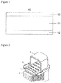
- FIG 2 illustrates a schematic diagram of a radiator.
- the radiator has a structure in which thin fins 2 processed in a corrugated shape are arranged between a plurality of tubes 1 formed in a flat shape.
- the tubes 1 and the fins 2 are formed as one unitary piece. Both ends of the tubes 1 are opened to spaces each formed of a header 3 and a tank 4.
- a high-temperature coolant is sent from a space of one tank to a space of the other tank through the tubes 1, and the coolant with a temperature reduced to a low temperature by heat exchange with the tubes 1 and the fins 2 is circulated.
- a brazing sheet is generally used for tubes of such heat exchangers.
- the brazing sheet includes a core material, an inner lining material, and a brazing material.
- the core material for example, JIS 3003 (Al-0.15 mass %Cu-1.1 mass %Mn) alloy is used.
- JIS 7072 Al-1 mass %Zn
- the brazing material On the external side of the core material, for example, JIS 4045 (Al-10 mass %Si) alloy is used as the brazing material.
- the tubes are bonded together with other materials, such as fins processed in a corrugated shape, as one unitary piece by brazing.
- a flux brazing method and a Nocolok brazing using a non-corrosive flux are mentioned as examples of the brazing method.
- Brazing is performed by heating each of the members to a temperature around 600°C.
- tubes of heat exchangers for automobiles are also required to improve in corrosion resistance of the external surface.
- Neutral to weak-alkaline aqueous solutions (long life coolant: LLC) including an antifreeze are used as cooling water for radiators and/or heater cores. Some types of such aqueous solutions have a pH of 10 or around.
- tubes using an Al-Zn based alloy for the sacrificial anode material there is the problem that no sufficient effect of preventing corrosion of the sacrificial anode material is obtained in such environments, and that penetration corrosion occurs early.
- Patent Literature 1 discloses an aluminum alloy clad material for heat exchangers excellent in corrosion resistance, in which an aluminum alloy brazing material is cladded onto one side surface of a core material made of an aluminum alloy, and a sacrificial anode material is cladded onto the other side surface of the core material, wherein the sacrificial anode material is formed of an aluminum alloy including an element to be coupled with A1 to generate a compound nobler than the matrix of the sacrificial anode material, with the balance being Al and impurities, and the compound with a grain size (diameter corresponding to a circle, the same is applicable hereinafter) of 1 ⁇ m to 10 ⁇ m exists in number of 5 ⁇ 10 2 to 5 ⁇ 10 4 per 1 mm 2 in the matrix.
- the aluminum alloy clad material for heat exchangers disclosed in Cited Document 1 is provided such that a compound with a grain size of 1 ⁇ m to 10 ⁇ m obtained by combination of an element with A1 and nobler than the matrix of the sacrificial anode material exists at a certain density in the sacrificial anode material.
- Patent Literature 1 Japanese Patent Publication No. H11-80871-A
- the inside of the radiator has a high pressure with the coolant when the pump operates, the tubes receive a force in a direction in which the sectional shape thereof expands, the header plate receives a force in a direction in which the caulking joint portion with the resin tank joined by caulking with the header plate is opened, and tensile stress acts on the sacrificial anode material.
- the tubes and/or the header plate may cause a fatigue fracture, and cause a problem in life and reliability.
- Cited Document 1 has insufficient fatigue property, and has the problem of an early fatigue fracture.
- an object of the present invention is to provide an aluminum alloy brazing sheet having excellent corrosion resistance and fatigue property even in heat exchangers in which cooling water flows in an alkali corrosive environment, and suitable for radiators and/or heater cores of heat exchangers for automobiles.
- the inventors of the present invention have found that excellent corrosion resistance and fatigue property can be provided to the aluminum alloy brazing sheet, by adopting specific chemical composition for the constituent material of the aluminum alloy brazing sheet, and dispersing single phase pure Si grains or grains of a Si-including intermetallic compound of a predetermined size in a predetermined number density in the sacrificial anode material, and have made the present invention.
- the present invention is an aluminum alloy brazing sheet comprising: a core material made of an aluminum alloy including 0.3 mass % to 1.2 mass % of Si, 0.1 mass % to 1.5 mass % of Cu, and 0.3 mass % to 2.0 mass % of Mn, the core material optionally including at least one or more of 0.01 mass % to 0.3 mass % of Cr, 0.01 mass % to 0.3 mass % of Zr, 0.01 mass % to 0.3 mass % of Ti, and 0.01 mass % to 0.3 mass % of V, the core material optionally including one or two of 0.05 mass % to 1.0 mass % of Fe and 0.1 mass % to 1.0 mass % of Mg, with the balance being Al and unavoidable impurities; a brazing material cladded onto one side surface of the core material, and made of an aluminum alloy including 4.0 to 13 mass % of Si, the brazing material optionally including 5.0 mass % or less of Zn, with the balance being Al and unavoidable impurities
- the present invention provides a method for manufacturing the aluminum alloy brazing sheet as defined above, comprising: manufacturing an aluminum alloy for a sacrificial anode material before being assembled as a clad material, wherein, in the manufacturing, a hot rolling temperature is set to 400°C to 500°C, and reduction of hot rolling is set to 50% to 90%.
- the present invention enables provision of an aluminum alloy brazing sheet having excellent corrosion resistance and fatigue property even in heat exchangers in which cooling water flows in an alkali corrosive environment, and suitable for radiators and/or heater cores of heat exchangers for automobiles.
- the present invention is an aluminum alloy brazing sheet comprising: a core material made of an aluminum alloy including 0.3 mass % to 1.2 mass % of Si, 0.1 mass % to 1.5 mass % of Cu, and 0.3 mass % to 2.0 mass % of Mn, the core material optionally including at least one or more of 0.01 mass % to 0.3 mass % of Cr, 0.01 mass % to 0.3 mass % of Zr, 0.01 mass % to 0.3 mass % of Ti, and 0.01 mass % to 0.3 mass % of V, the core material optionally including one or two of 0.05 mass % to 1.0 mass % of Fe and 0.1 mass % to 1.0 mass % of Mg, with the balance being Al and unavoidable impurities; a brazing material cladded onto one side surface of the core material, and made of an aluminum alloy including 4.0 mass % to 13 mass % of Si, the brazing material optionally including 5.0 mass % or less of Zn, with the balance being Al and unavoidable im
- FIG. 1 illustrates an example of a form of an aluminum alloy brazing sheet according to the present invention.
- an aluminum alloy brazing sheet 10 is formed of a core material 11, a brazing material 12, and a sacrificial anode material 13.
- the brazing material 12 is cladded onto one side surface of the core material 11, and the sacrificial anode material 13 is cladded onto the other side surface of the core material 11.
- the aluminum alloy brazing sheet according to the present invention includes a core material, a brazing material cladded onto one side surface of the core material, and a sacrificial anode material cladded onto the other side surface of the core material.
- the sacrificial anode material according to the aluminum alloy brazing sheet of the present invention that is, the sacrificial anode material cladded onto the core material in the aluminum alloy brazing sheet of the present invention is made of an aluminum alloy, and includes Zn and Si as indispensable compositions.
- the sacrificial anode material is made of an aluminum alloy including 1.0 mass % to 8.0 mass % of Zn and 0.5 mass % to 1.5 mass % of Si, with the balance being Al and unavoidable impurities.
- Zn in the sacrificial anode material changes the potential of the sacrificial anode material to a lower potential to maintain the sacrificial anode effect for the core material and prevent pitting corrosion and/or crevice corrosion of the core material.
- the Zn content in the sacrificial anode material is 1.0 mass % to 8.0 mass %, and preferably 4.0 mass % to 7.0 mass %.
- Zn content in the sacrificial anode material is lower than the range described above, Zn produces no sufficient effect.
- the Zn content exceeds the range described above, the corrosion speed becomes too high, the sacrificial anode material disappears early, and corrosion resistance is reduced.
- Si exists as single phase pure Si, or exists together with an element, such as Fe, Mg, and Mn, to form an Al-Fe-Si based, Al-Fe-Si-Mn based, Al-Mn-Si based, or Mg-Si based intermetallic compound including Si.
- an element such as Fe, Mg, and Mn
- the Si content in the sacrificial anode material is 0.5 mass % to 1.5 mass %, and preferably 0.7 mass % to 1.3 mass %.
- the Si content in the sacrificial anode material is lower than the range described above, the total number density of single phase pure Si and the Si-including intermetallic compound does not fall within the range of 1 ⁇ 10 3 /mm 2 or more and 1 ⁇ 10 6 /mm 2 or less, the effect described above is not sufficiently obtained.
- the Si content exceeds the range described above, the solidus temperature of the sacrificial anode material becomes too low, and the sacrificial anode material is molten.
- the sacrificial anode material may include at least one or more of 0.01 mass % to 0.3 mass % of Cr, 0.01 mass % to 0.3 mass % of Zr, 0.01 mass % to 0.3 mass % of Ti, and 0.01 mass % to 0.3 mass % of V.
- Cr, Zr, Ti, and V forms a fine intermetallic compound in the sacrificial anode material, and improves the strength of the material.
- the content of Cr, Zr, Ti, or V in the sacrificial anode material is lower than the range described above, the effect described above is not sufficiently obtained.
- the Cr content in the sacrificial anode material is preferably 0.05 mass % to 0.2 mass %
- the Zr content is preferably 0.05 mass % to 0.2 mass %
- the Ti content is preferably 0.05 mass % to 0.2 mass %
- the V content is preferably 0.05 mass % to 0.2 mass %.
- the sacrificial anode material may include one or two of 0.05 mass % to 0.5 mass % of Fe and 0.1 mass % to 2.5 mass % of Mg.
- Each of Fe and Mg forms an Al-Fe-Si based, Al-Fe-Si based, or Mg-Si based intermetallic compound together with Si in the sacrificial anode material.
- progress of cathode reaction is promoted on the surface of the intermetallic compound. For this reason, pitting corrosion is scattered, and localization of pitting corrosion is suppressed. As a result, progress of pitting corrosion in the depth direction is suppressed, and the life until corrosion penetration is prolonged.
- the Fe content in the sacrificial anode material if present is 0.05 mass % to 0.5 mass %, and preferably 0.1 mass % to 0.3 mass %.
- the Fe content in the sacrificial anode material is lower than the range described above, the effect described above is not sufficiently obtained.
- the Fe content exceeds the range described above, self-corrosion resistance decreases, and the sacrificial anode material is worn early. As a result, the sacrificial anti-corrosion effect cannot be obtained, and penetration occurs early.
- the Mg content in the sacrificial anode material if present is 0.1 mass % to 2.5 mass %, and preferably 0.2 mass % to 2.0 mass %.
- the Mg content in the sacrificial anode material is lower than the range described above, the effect described above is not sufficiently obtained.
- the Mg content exceeds the range described above, self-corrosion resistance decreases, and the sacrificial anode material is worn early. As a result, the sacrificial anti-corrosion effect cannot be obtained, and penetration occurs early.
- the core material according to the aluminum alloy brazing sheet according to the present invention is made of an aluminum alloy, and includes Si, Cu, and Mn as indispensable compositions.
- the core material is made of an aluminum alloy including 0.3 mass % to 1.2 mass % of Si, 0.1 mass % to 1.5 mass % of Cu, and 0.3 mass % to 2.0 mass % of Mn, with the balance being Al and unavoidable impurities.
- Cu in the core material increases strength of the core material, and causes the potential of the core material to be noble to increase the potential difference from the sacrificial anode material and the potential difference from the brazing material and improve corrosion resistance.
- Cu in the core material is diffused into the sacrificial anode material and the brazing material in brazing heating to form a gentle Cu concentration gradient.
- the potential on the core material side becomes noble and the potential on the sacrificial anode material surface side or the brazing material surface side becomes lowered, and gentle potential distribution is formed in the thickness direction of the sacrificial anode material or the brazing material to cause their corrosion forms to be a whole surface corrosion type.
- the Cu content in the core material is 0.1 mass % to 1.5 mass %, and preferably 0.5 mass % to 1.3 mass %.
- the Cu content in the core material is lower than the range described above, the effect thereof is small.
- the Cu content exceeds the range described above, corrosion resistance of the core material decreases, the melting point of the core material decreases, and local melting occurs in brazing heating.
- Mn in the core material increases strength of the core material, and causes the potential of the core material to be noble to increase the potential difference from the sacrificial anode material and the potential difference from the brazing material and improve corrosion resistance. Mn also changes the potential in the core material to be noble, and functions to increase the difference in potential from the sacrificial anode material and improve corrosion resistance.
- the Mn content in the core material is 0.3 mass % to 2.0 mass %, and preferably 1.0 mass % to 1.9 mass %. When the Mn content in the core material is lower than the range described above, the effect thereof is small. When the Mn content exceeds the range described above, a coarse compound is generated in casting to damage rolling processability, and consequently a sound sheet material is not easily obtained.
- Si in the core material has a function of improving strength of the core material by solute strengthening and fine precipitation hardening of Al-Mn-Si based or Mg-Si based intermetallic compound.
- the Si content in the core material is 0.3 mass % to 1.2 mass %, and preferably 0.4 mass % to 1.0 mass %. When the Si content in the core material is lower than the range described above, the effect thereof is not sufficient. When the Si content exceeds the range described above, corrosion resistance decreases, the melting point of the core material decreases, and local melting easily occurs in brazing.
- the core material may further include at least one or more of 0.01 mass % to 0.3 mass % of Cr, 0.01 mass % to 0.3 mass % of Zr, 0.01 mass % to 0.3 mass % of Ti, and 0.01 mass % to 0.3 mass % of V.
- Cr, Zr, Ti, and V forms a fine intermetallic compound in the core material to improve strength of the material.
- the content of Cr, Zr, Ti, or V in the core material is lower than the range described above, the effect thereof is not sufficient.
- the content exceeds the range described above, a coarse compound is generated in casting to damage rolling processability, and consequently a sound sheet material is not easily obtained.
- the Cr content in the core material is preferably 0.05 mass % to 0.2 mass %
- the Zr content is preferably 0.05 mass % to 0.2 mass %
- the Ti content is preferably 0.05 mass % to 0.2 mass %
- the V content is preferably 0.05 mass % to 0.2 mass %.
- the core material may further include one or two of 0.05 mass % to 1.0 mass % of Fe and 0.1 mass % to 1.0 mass % of Mg.
- Fe and Mg in the core material have a function of improving strength of the core material by fine precipitation hardening of Al-Fe-Si based, Al-Fe-Si-Mn based, or Mg-Si based intermetallic compound together with Si or Mn.
- the Fe content in the core material if present is 0.05 mass % to 1.0 mass %, and preferably 0.1 mass % to 0.5 mass %. When the Fe content in the core material is lower than the range described above, the effect is not sufficient. When the range exceeds the range described above, the grains after grazing become fine, and erosion occurs.
- the Mg content in the core material if present is 0.1 mass % to 1.0 mass %, and preferably 0.2 mass % to 0.5 mass %.
- the effect described above is not sufficient.
- Mg content exceeds the range described above, Mg is diffused into the surface of the brazing material in brazing under the atmosphere using a noncorrosive flux, and brazability markedly reduces.
- the brazing material cladded onto the core material is made of an aluminum alloy, and includes Si as an indispensable composition.
- the brazing material is made of an aluminum alloy including 4.0 mass % to 13 mass % of Si, with the balance being Al and unavoidable impurities.
- Si in the brazing material lowers the melting point of Al to enhance the flowability and cause the function of brazing filler metal to exert.
- the content of Si in the brazing material is 4.0 mass % to 13 mass %, and preferably 7.0 mass % to 12 mass %.
- the Si content in the brazing material is lower than the range described above, the flowability decreases, and the brazing material does not effectively function as the brazing filler metal.
- the Si content exceeds the range described above, erosion to the core material or the other bonded portions increases.
- the brazing material may further include Zn in addition to Si.
- Zn in the brazing material is capable of lowering the potential of the brazing material, and provides the brazing material with a sacrificial corrosion resistance effect.
- the Zn content in the brazing material if present is 5.0 mass % or less, preferably 0.3 mass % to 5.0 mass %, and particularly preferably 0.8 mass % to 4.0 mass %.
- the Zn content in the brazing material is lower than the range described above, the degree of lowering the potential is small, and the sacrificial corrosion resistance effect easily becomes insufficient.
- the Zn content exceeds the range described above, the self-corrosion speed of the brazing material increases, and the corrosion resistance of the brazing material deteriorates.
- the total number density of single phase pure Si and the Si-including intermetallic compound with the grain size of 0.1 ⁇ m or more and 1.0 ⁇ m or less and existing in the sacrificial anode material cladded onto the core material is 1 ⁇ 10 3 /mm 2 or more and 1 ⁇ 10 6 /mm 2 or less.
- the total number density of single phase pure Si and the Si-including intermetallic compound with the grain size of 0.1 ⁇ m or more and 1.0 ⁇ m or less is lower than 1 ⁇ 10 3 /mm 2 .
- pitting corrosion is not scattered, but pitting corrosion progresses in the depth direction, and penetration occurs early.
- the total number density of single phase pure Si and the Si-including intermetallic compound with the grain size of 0.1 ⁇ m to 1.0 ⁇ m and existing in the sacrificial anode material cladded onto the core material is 1 ⁇ 10 3 /mm 2 to 1 ⁇ 10 6 /mm 2 .
- the aluminum alloy brazing sheet according to the present invention is manufactured by cladding a brazing material made of an alloy of the composition described above onto one side surface of a core material formed in a sheet shape of an alloy of the composition described above, and cladding a sacrificial anode material made of an alloy of the composition described above on the other surface of the core material.
- ingots are prepared by melting and casting each of aluminum alloys having respective desired chemical compositions used for the core material, the sacrificial anode material, and the brazing material.
- the methods of melting and casting are not specifically limited, but ordinary methods are used.
- the aluminum alloy for the core material and the aluminum alloy for the sacrificial anode material are subjected to no homogenization, or subjected to homogenization at a temperature of 500°C or less, and the aluminum alloy for the brazing material and the aluminum alloy for the sacrificial anode material are subjected to hot rolling to respective predetermined thicknesses.
- the hot rolling temperature of the aluminum alloy for the sacrificial anode material is set to 400°C to 500°C, and preferably 420°C to 480°C, to set the grain size of single phase pure Si and the Si-including intermetallic compound in the sacrificial anode material after cladding to 0.1 ⁇ m to 1.0 ⁇ m.
- Single phase pure Si and the Si-including intermetallic compound are precipitated during hot rolling, and the grain size of single phase pure Si and the Si-including intermetallic compound change according to the hot rolling temperature.
- the hot rolling temperature of the aluminum alloy for the sacrificial anode material when the hot rolling temperature of the aluminum alloy for the sacrificial anode material is too high, single phase pure Si and the Si-including intermetallic compound are coarsened. Setting the hot rolling temperature of the aluminum alloy for the sacrificial anode material within the range described above causes no coarsening in single phase pure Si and the Si-including intermetallic compound precipitated finely in hot rolling, and produces single phase pure Si and the Si-including intermetallic compound with the grain size of 1.0 ⁇ m or less. By contrast, when the hot rolling temperature of the aluminum alloy for the sacrificial anode material is lower than the range described above, deformation resistance in hot rolling is large, and hot rolling becomes difficult.
- the hot rolling temperature exceeds the range described above, the grain size of single phase pure Si and the Si-including intermetallic compound in the sacrificial anode material is coarsened to exceed 1.0 ⁇ m, and the number density thereof is reduced.
- the hot rolling temperature being 400°C to 500°C, and preferably 420°C to 480°C means that the temperature of the aluminum alloy directly before hot rolling and the temperature of the aluminum alloy from the start to the end of hot rolling fall within the range of 400°C to 500°C, and preferably 420°C to 480°C.
- the reduction of hot rolling of the aluminum alloy for the sacrificial anode material is set to 50% to 90%, to set the total number density of single phase pure Si and the Si-including intermetallic compound with the grain size of 0.1 ⁇ m to 1.0 ⁇ m in the sacrificial anode material after cladding to 1 ⁇ 10 3 /mm 2 or more and 1 ⁇ 10 6 /mm 2 or less.
- Single phase pure Si and the Si-including intermetallic compound are precipitated during hot rolling, and single phase pure Si and the Si-including intermetallic compound are precipitated much on dislocation introduced during hot rolling.
- the dislocation quantity increases, the number density of single phase pure Si and the Si-including intermetallic compound increases, and the grain size becomes fine.
- the reduction of hot rolling of the aluminum alloy for the sacrificial anode material is lower than the range described above, the dislocation quantity introduced into the aluminum alloy for the sacrificial anode material is small, precipitation is difficult to occur, and the number density described above cannot be obtained.
- the reduction exceeds the range described above the dislocation quantity introduced into the aluminum alloy for the sacrificial anode material becomes too much, excessive precipitation occurs, and the density of the compound exceeds the predetermined quantity.
- the temperature at which hot rolling of the aluminum alloy for the sacrificial anode material is not particularly limited.
- the sacrificial anode material rolled to a predetermined thickness is not wound in a coil shape, but retained in a sheet shape. For this reason, after hot rolling, the hot-rolled material of the aluminum alloy for the sacrificial anode material is more easily cooled than in the case where it is wound in a coil shape, and causes no coarsening of single phase pure Si and the Si-including intermetallic compound.
- the materials are combined to form a clad material by hot rolling at 400°C to 500°C by a conventional method.
- the clad material is subjected to cold rolling to a predetermined thickness in the end, to manufacture the aluminum alloy brazing sheet according to the present invention.
- the clad material may be annealed (intermediate annealing) in the midway of the cold rolling process, or may be annealed (final annealing) thereafter.
- the annealing temperature is 200°C to 400°C, and preferably 200°C to 300°C. When the annealing temperature is lower than the range described above, the grain size of the core material after brazing heating is fine, and erosion occurs in the core material.
- the annealing temperature exceeds the range described above, single phase pure Si and the Si-including intermetallic compound in the sacrificial anode material are coarsened, and the density thereof decreases.
- the annealing may be intermediate annealing performed before the clad material reaches the final thickness, or final annealing performed after the clad material is reduced to the final thickness. Only one or both of intermediate annealing and final annealing may be performed.
- the method for manufacturing an aluminum alloy brazing sheet according to the present invention is a manufacturing method for manufacturing the aluminum alloy brazing sheet according to the present invention, wherein in a manufacturing process of an aluminum alloy for the sacrificial anode material before combined as a clad material, the hot rolling temperature is set to 400°C to 500°C, and the reduction of hot rolling is set to 50% to 90%.
- each of the core material, the sacrificial anode material, and the brazing material was manufactured under manufacturing conditions listed in Table 4 using alloys having respective compositions listed in Table 1, Table 2, and Table 3.
- the mark "-" means that the element is equal to or less than the detection limit, and the term “balance” includes unavoidable impurities.
- DC casting was performed to cast an aluminum alloy listed in Table 1 and used for the core material, the aluminum alloy listed in Table 2 and used for the sacrificial anode material, and the aluminum alloy listed in Table 3 and used for the brazing material, and facing was further performed.
- the ingot for the sacrificial anode material was subjected to heating at temperatures listed in Table 4, and thereafter subjected to hot rolling with the reduction listed in Table 4.
- the ingot for the brazing material was subjected to heating at 480°C, and thereafter subjected to hot rolling to a predetermined thickness.
- the hot-rolled aluminum alloy for the sacrificial anode material was cladded onto one side surface of the ingot for the core material, and the aluminum alloy for the brazing material was cladded onto the other side surface thereof, to form a joined material (clad material) with the clad ratio of 15% for the sacrificial anode material, and 10% for the brazing material.
- the joined material was heated at 480°C, and thereafter rolled to 2.6 mm by hot clad rolling. Thereafter, the obtained rolled material was subjected to cold rolling, and subjected to intermediate annealing or final annealing, or both of them under the conditions listed in Table 4 to obtain sample materials. In the case of performing intermediate annealing, the final reduction was regulated to 30%. In the case of performing no intermediate annealing, the rolled material was subjected to cold annealing to the final thickness of 0.25 mm, and thereafter subjected to final annealing to obtain sample materials.
- the grain size of single phase pure Si and the Si-including intermetallic compound with 0.1 ⁇ m or more and 1.0 ⁇ m or less can be determined by observing the sacrificial anode material with a scanning electron microscope (SEM) and analyzing the SEM image.
- SEM scanning electron microscope
- the term "grain size" means the circle equivalent diameter.
- the observed part is any part of the sacrificial anode material, such as any section along the thickness direction and/or a section parallel with the sheet material surface. From the viewpoint of convenience, measurement is preferably performed on any section along the thickness direction.
- the total number density of single phase pure Si and the Si-including intermetallic compound with the grain size of 0.1 ⁇ m or more and 1.0 ⁇ m or less is determined by observing the sacrificial anode material with an SEM and analyzing the SEM image.
- the observed part is any part of the sacrificial anode material, such as any section along the thickness direction and a section parallel with the sheet material surface. From the viewpoint of convenience, measurement is preferably performed on any section along the thickness direction.
- each of the sample material prepared as described above was subjected to brazing-equivalent heating for 3 minutes at 600°C, and thereafter cooled at a speed of 50°C/min. Thereafter, the values of "tensile strength”, “fatigue strength”, “internal surface corrosion resistance”, “external surface corrosion resistance”, “fin bonding ratio”, “occurrence of erosion”, and “formability" of each of the sample materials were evaluated by the method described later.
- a JIS No. 5 test piece was cut out of each of the sample materials.
- Each of the test pieces was subjected to the brazing-equivalent heating, thereafter left for one week at a room temperature, and subjected to tensile test compliant with JIS Z 2241:2011.
- the samples with the tensile strength of 150 MPa or more were regarded as passed samples, and the samples with the tensile strength lower than 150 MPa were regarded as failed samples.
- a fatigue test piece (JIS Z 2275 No. 1 test piece) was cut out of each of the sample materials. Each of the test pieces was subjected to the brazing-equivalent heating, and thereafter left for one week at a room temperature. Each of the test pieces was subjected to pulsating plain bending fatigue test (compliant with JIS Z 2275) in which fixed stress 70 MPa is repeatedly loaded on a flat portion on the internal surface skin material side of the clad material at a frequency of 25 Hz at a room temperature, to measure the fracture life of the clad material. The samples with the measured fracture life of one million times or longer were evaluated as passed samples (o), and the samples with the measured fracture life shorter than one million times were evaluated as failed samples (x).
- the sacrificial anode material surface of each of the sample materials subjected to heating equivalent to brazing was subjected to immersion test simulating an acidic environment in a water-based coolant.
- the test surface of the test piece of each of the sample materials was immersed in an aqueous solution including 195 ppm of Cl - , 60 ppm of SO 4 2- , 1 ppm of Cu 2+ , and 30 ppm of Fe 2+ , at a temperature of 88°C for 8 hours with the solution volume to specimen area ratio of 10 mL/cm 2 , and thereafter each of the test pieces was left at 25°C for 16 hours. Such a cycle was performed for 3 months. After the immersion cycle test, the cases where no penetration occurred were evaluated as passed samples (o), and the case where penetration occurred were evaluated as failed samples (x). The part other than the test surface was masked to prevent contact with the test aqueous solution.
- the sacrificial anode material surface of each of the sample materials subjected to heating equivalent to brazing was subjected to immersion test simulating an alkaline environment in a water-based coolant.
- the test surface of the test piece of each of the sample materials was immersed in an aqueous solution including 195 ppm of Cl - , 60 ppm of SO 4 2- , 1 ppm of Cu 2+ , and 30 ppm of Fe 2+ and regulated to a pH of 10 with NaOH, at a temperature of 88°C for 8 hours with the solution volume to specimen area ratio of 10 mL/cm 2 , and thereafter each of the test pieces was left at 25°C for 16 hours.
- Such a cycle was performed for 3 months.
- the cases where no penetration occurred were evaluated as passed samples (o), and the case where penetration occurred were evaluated as failed samples (x).
- the part other than the test surface was masked to prevent contact with the test aqueous solution.
- the fin material made of an alloy obtained by adding 1.5% of Zn to JIS 3003 alloy was corrugated, and assembled with the brazing material surface of each of the brazing sheet samples. Thereafter, the assembled samples were immersed in a 10% fluoride flux suspension, dried at 200°C, and thereafter subjected to brazing heating at 600°C ⁇ 3 minutes to prepare test cores.
- the brazing material surfaces of the test cores were subjected to SWAAT test for 500 hours on the basis of ASTM-G85. After the test, a corrosive on the surface of each of the test pieces was removed, and the corrosion depth was measured. In each test piece, 10 parts were measured, and the maximum value of the parts was evaluated as the corrosion depth.
- the samples with the corrosion depth smaller than 70 ⁇ m were evaluated as excellent samples (oo), the samples with the corrosion depth of 70 ⁇ m or more and 90 ⁇ m or less were evaluated as good samples (o), and the samples with the corrosion depth exceeding 90 ⁇ m and the samples in which penetration occurred were evaluated as failed samples ( ⁇ ).
- the part other than the test surface was masked to prevent contact with the test aqueous solution.
- the fin material made of an alloy obtained by adding 1.5% of Zn to JIS 3003 alloy was corrugated, and assembled with the brazing material surface of each of the brazing sheet samples. Thereafter, the assembled samples were immersed in a 10% fluoride flux suspension, dried at 200°C, and thereafter subjected to brazing heating at 600°C ⁇ 3 minutes to prepare test cores. In the test cores, the ratio of the number of tops of bonded fins to the total number of tops of the fins was evaluated as the fin bonding ratio.
- the samples with the fin bonding ratio of 95% or more were evaluated as passed samples (o) in brazability, and the samples with the fin bonding ratio lower than 95% were evaluated as failed samples ( ⁇ ) in brazability.
- the micro-observation was performed on the test core sections prepared in above item (h) to check occurrence of erosion (diffusion of brazing filler metal) and melting of the material in the core material and/or the sacrificial anode material.
- the samples in which neither erosion nor melting of the material was occurred were evaluated as passed samples (o), and the samples in which at least one of erosion and melting of the material occurred were evaluated as failed samples ( ⁇ ).
- Examples 1 to 74 satisfied the conditions provided in the present invention, and passed or exhibited a good result in each of items of the strength after brazing, the fatigue strength after brazing, the internal surface corrosion resistance (under acidic environment and alkaline environment), the external surface corrosion resistance, the fin bonding ratio, and erosion resistance.
- Comparative Example 1 because the Si content of the brazing material was too small, some fins were not bonded, and Comparative Example 1 failed in brazability.
- Comparative Example 2 because the Si content of the brazing material was too large, erosion of the core material occurred, and Comparative Example 2 failed in the test.
- Comparative Example 3 because the Zn content of the brazing material was too large, the self-corrosion speed of the brazing material increased, and Comparative Example 3 failed in external surface corrosion resistance.
- Comparative Example 4 because the Si content of the sacrificial anode material was too small, the total number density of single phase pure Si and the Si-including intermetallic compound was small, and Comparative Example 4 failed in internal surface corrosion resistance in alkaline environment.
- Comparative Example 5 because the Si content of the sacrificial anode material was too large, the melting point of the sacrificial anode material decreased, erosion occurred after brazing heating, and Comparative Example 5 failed in the test.
- Comparative Example 6 because the Zn content of the sacrificial anode material was too small, no sacrificial corrosion resistance effect was produced, and Comparative Example 6 failed in internal surface corrosion resistance.
- Comparative Example 7 because the Zn content of the sacrificial anode material was too large, the self-corrosion speed thereof increased, and Comparative Example 7 failed in internal surface corrosion resistance.
- Comparative Example 10 because the Ti content of the sacrificial anode material was too large, a coarse compound was generated in casting to damage rolling processability, and no sound sheet material was produced.
- Comparative Example 12 because the Fe content of the sacrificial anode material was too large, the compound density exceeded the predetermined quantity, and Comparative Example 12 failed in internal surface corrosion resistance in alkaline environment.
- Comparative Example 13 because the Mg content of the sacrificial anode material was too large, the compound density exceeded the predetermined quantity, and Comparative Example 13 failed in internal surface corrosion resistance in alkaline environment.
- Comparative Example 14 because the Si content of the core material was too small, the precipitation quantity of an Al-Mn-Si based compound was small, the strength decreased, and Comparative Example 14 failed in strength after brazing.
- Comparative Example 15 because the Si content of the core material was too large, the melting point decreased, erosion occurred after brazing heating, and Comparative Example 15 failed in the test.
- Comparative Example 16 because the Cu content of the core material was too small, strength after brazing was small, and Comparative Example 16 failed in the test. In addition, because the potential difference from the sacrificial anode material was insufficient, Comparative Example 16 failed in internal surface corrosion resistance.
- Comparative Example 17 because the Cu content of the core material was too large, the melting point decreased, erosion occurred after brazing heating, and Comparative Example 17 failed in the test.
- Comparative Example 18 because the Mn content of the core material was too small, strength after brazing was small, and Comparative Example 18 failed in the test. In addition, because the potential difference from the sacrificial anode material was insufficient, Comparative Example 18 failed in internal surface corrosion resistance.
- Comparative Example 19 because the Mn content of the core material was too large, a coarse compound was generated in casting to damage rolling processability, and no sound sheet material was produced.
- Comparative Example 20 because the Cr content of the core material was too large, a coarse compound was generated in casting to damage rolling processability, and no sound sheet material was produced.
- Comparative Example 24 because the Fe content of the core material was too large, grains after brazing became fine to cause erosion, and Comparative Example 24 failed in the test.
- Comparative Example 25 because the Mg content of the core material was too large, Mg was diffused to the surface of the brazing material in brazing, consequently some fins were not bonded, and Comparative Example 25 failed in brazability.
- Comparative Example 27 because the start temperature of hot rolling of the sacrificial anode material was too high, the grain size of single phase pure Si and the Si-including intermetallic compound in the sacrificial anode material was coarsened to 1 ⁇ m or more, Comparative Example 27 failed in fatigue strength. In addition, because the total number density of single phase pure Si and the Si-including intermetallic compound was small, Comparative Example 27 failed in internal surface corrosion resistance in alkaline environment.
- Comparative Example 28 because the reduction of hot rolling of the sacrificial anode material was too low, precipitation is difficult to occur, the total number density of single phase pure Si and the Si-including intermetallic compound decreased, and Comparative Example 28 failed in internal surface corrosion resistance in alkaline environment.
- Comparative Example 29 because the reduction of hot rolling of the sacrificial anode material was too high, precipitation excessively occurred, the total number density of single phase pure Si and the Si-including intermetallic compound increased, and corrosion speed under alkaline environment increased, and Comparative Example 29 failed in internal surface corrosion resistance in alkaline environment.
- Comparative Example 30 because the final annealing temperature of the clad material was too low, the grain size of the core material became fine after brazing heating, erosion occurred in the core material, and Comparative Example 30 failed in the test.
- Comparative Example 31 because the final annealing temperature of the clad material was too high, the grain size of single phase pure Si and the Si-including intermetallic compound in the sacrificial anode material was coarsened to 1 ⁇ m or more, Comparative Example 31 failed in fatigue strength. In addition, because the total number density of single phase pure Si and the Si-including intermetallic compound was small, Comparative Example 31 failed in internal surface corrosion resistance in alkaline environment.
Landscapes
- Chemical & Material Sciences (AREA)
- Engineering & Computer Science (AREA)
- Mechanical Engineering (AREA)
- Materials Engineering (AREA)
- Metallurgy (AREA)
- Organic Chemistry (AREA)
- Physics & Mathematics (AREA)
- Thermal Sciences (AREA)
- Crystallography & Structural Chemistry (AREA)
- Laminated Bodies (AREA)
- Prevention Of Electric Corrosion (AREA)
Applications Claiming Priority (2)
| Application Number | Priority Date | Filing Date | Title |
|---|---|---|---|
| JP2016241772A JP6868383B2 (ja) | 2016-12-14 | 2016-12-14 | アルミニウム合金ブレージングシートの製造方法 |
| PCT/JP2017/043267 WO2018110320A1 (ja) | 2016-12-14 | 2017-12-01 | アルミニウム合金ブレージングシート及びその製造方法 |
Publications (3)
| Publication Number | Publication Date |
|---|---|
| EP3556874A1 EP3556874A1 (en) | 2019-10-23 |
| EP3556874A4 EP3556874A4 (en) | 2020-05-06 |
| EP3556874B1 true EP3556874B1 (en) | 2021-11-17 |
Family
ID=62558578
Family Applications (1)
| Application Number | Title | Priority Date | Filing Date |
|---|---|---|---|
| EP17881212.9A Active EP3556874B1 (en) | 2016-12-14 | 2017-12-01 | Aluminum alloy brazing sheet and method for manufacturing same |
Country Status (5)
| Country | Link |
|---|---|
| US (1) | US11260476B2 (ja) |
| EP (1) | EP3556874B1 (ja) |
| JP (1) | JP6868383B2 (ja) |
| CN (1) | CN110073013B (ja) |
| WO (1) | WO2018110320A1 (ja) |
Families Citing this family (3)
| Publication number | Priority date | Publication date | Assignee | Title |
|---|---|---|---|---|
| JP2020093279A (ja) * | 2018-12-12 | 2020-06-18 | 三菱アルミニウム株式会社 | 根付部の耐食性に優れた熱交換器用多層クラッド材および熱交換器 |
| JP2021063263A (ja) * | 2019-10-11 | 2021-04-22 | パナソニックIpマネジメント株式会社 | 熱交換器用ブレージングシートおよび熱交換器用ブレージングシートの接合構造、並びに、熱交換器 |
| CN115125419B (zh) * | 2022-05-27 | 2023-01-24 | 东北轻合金有限责任公司 | 一种高强自钎焊铝合金材料及其制备方法 |
Family Cites Families (10)
| Publication number | Priority date | Publication date | Assignee | Title |
|---|---|---|---|---|
| JP3763498B2 (ja) | 1997-09-08 | 2006-04-05 | 住友軽金属工業株式会社 | 耐食性に優れた熱交換器用アルミニウム合金クラッド材 |
| JP4111456B1 (ja) * | 2006-12-27 | 2008-07-02 | 株式会社神戸製鋼所 | 熱交換器用アルミニウム合金ブレージングシート |
| JP4832354B2 (ja) * | 2007-04-13 | 2011-12-07 | 株式会社デンソー | 耐久性に優れた高強度、高融点熱交換器用アルミニウム合金クラッド材とその製造方法、およびアルミニウム合金製熱交換器 |
| JP5388084B2 (ja) * | 2007-07-27 | 2014-01-15 | 三菱アルミニウム株式会社 | 強度および耐孔食性に優れる熱交換器用アルミニウム合金クラッド材 |
| JP5336967B2 (ja) * | 2009-07-28 | 2013-11-06 | 株式会社神戸製鋼所 | アルミニウム合金クラッド材 |
| JP5339560B1 (ja) * | 2012-11-14 | 2013-11-13 | 古河スカイ株式会社 | アルミニウム合金ブレージングシート及びその製造方法 |
| CN106170571B (zh) * | 2014-04-22 | 2018-04-10 | 株式会社Uacj | 铝制包层材料和它的制造方法、热交换器用铝制包层材料和它的制造方法、以及使用了该热交换器用铝制包层材料的铝制热交换器和它的制造方法 |
| JP6399438B2 (ja) * | 2014-06-16 | 2018-10-03 | 三菱アルミニウム株式会社 | 熱交換器 |
| JP6300747B2 (ja) * | 2015-03-17 | 2018-03-28 | 株式会社神戸製鋼所 | アルミニウム合金製ブレージングシート |
| JP6372950B2 (ja) * | 2015-07-08 | 2018-08-15 | 株式会社デンソー | アルミニウム合金クラッド材及びその製造方法 |
-
2016
- 2016-12-14 JP JP2016241772A patent/JP6868383B2/ja active Active
-
2017
- 2017-12-01 CN CN201780077268.7A patent/CN110073013B/zh active Active
- 2017-12-01 US US16/467,277 patent/US11260476B2/en active Active
- 2017-12-01 WO PCT/JP2017/043267 patent/WO2018110320A1/ja unknown
- 2017-12-01 EP EP17881212.9A patent/EP3556874B1/en active Active
Also Published As
| Publication number | Publication date |
|---|---|
| CN110073013B (zh) | 2021-01-12 |
| CN110073013A (zh) | 2019-07-30 |
| JP6868383B2 (ja) | 2021-05-12 |
| US11260476B2 (en) | 2022-03-01 |
| WO2018110320A1 (ja) | 2018-06-21 |
| US20200070286A1 (en) | 2020-03-05 |
| EP3556874A4 (en) | 2020-05-06 |
| JP2018095925A (ja) | 2018-06-21 |
| EP3556874A1 (en) | 2019-10-23 |
Similar Documents
| Publication | Publication Date | Title |
|---|---|---|
| EP2447662B1 (en) | Heat exchanger made from aluminum alloy, and process for production of coolant passage tube for use in the heat exchanger | |
| EP2431121B2 (en) | High-strength aluminum alloy brazing sheet, and method of manufacturing such sheet | |
| US6465113B2 (en) | Aluminum alloy brazing sheet for a heat exchanger | |
| CN107428128B (zh) | 多层铝钎焊板材料 | |
| EP3424615B1 (en) | Brazing sheet core alloy for heat exchanger | |
| EP2489750B1 (en) | Highly corrosion-resistant aluminum alloy brazing sheet, process for production of the brazing sheet, and highly corrosion-resistant heat exchanger equipped with the brazing sheet | |
| EP3374123B1 (en) | Brazing sheet and production method | |
| EP3418408A1 (en) | Aluminum alloy brazing sheet, manufacturing method therefor, and manufacturing method for vehicle heat exchanger using said brazing sheet | |
| EP3556874B1 (en) | Aluminum alloy brazing sheet and method for manufacturing same | |
| EP3670688B1 (en) | Aluminum alloy-brazing sheet for heat exchanger | |
| JP4220410B2 (ja) | 熱交換器用アルミニウム合金クラッド材 | |
| EP3663423B1 (en) | Aluminum alloy brazing sheet for heat exchanger | |
| JP4030006B2 (ja) | アルミニウム合金クラッド材およびその製造方法 | |
| EP3321384B1 (en) | Aluminum alloy cladding material, manufacturing method therefor, and heat exchanger using said aluminum alloy cladding material | |
| JP4220411B2 (ja) | 熱交換器用アルミニウム合金クラッド材 | |
| JP6970841B2 (ja) | アルミニウム合金ブレージングシート及びその製造方法 | |
| JP2004225062A (ja) | 耐食性に優れたアルミニウム合金クラッドチューブ材および該クラッドチューブ材を組付けた熱交換器 | |
| CN117002104A (zh) | 一种用于换热器的换热管及换热器 | |
| JP2581868B2 (ja) | 熱交換器用高強度高耐食性アルミニウム合金クラッド材 | |
| JP2018154890A (ja) | 耐食性に優れた熱交換器用アルミニウム合金クラッド材 | |
| JPH07116545B2 (ja) | 熱交換器用高強度高耐食性アルミニウム合金クラッド材 |
Legal Events
| Date | Code | Title | Description |
|---|---|---|---|
| STAA | Information on the status of an ep patent application or granted ep patent |
Free format text: STATUS: THE INTERNATIONAL PUBLICATION HAS BEEN MADE |
|
| PUAI | Public reference made under article 153(3) epc to a published international application that has entered the european phase |
Free format text: ORIGINAL CODE: 0009012 |
|
| STAA | Information on the status of an ep patent application or granted ep patent |
Free format text: STATUS: REQUEST FOR EXAMINATION WAS MADE |
|
| 17P | Request for examination filed |
Effective date: 20190619 |
|
| AK | Designated contracting states |
Kind code of ref document: A1 Designated state(s): AL AT BE BG CH CY CZ DE DK EE ES FI FR GB GR HR HU IE IS IT LI LT LU LV MC MK MT NL NO PL PT RO RS SE SI SK SM TR |
|
| AX | Request for extension of the european patent |
Extension state: BA ME |
|
| DAV | Request for validation of the european patent (deleted) | ||
| DAX | Request for extension of the european patent (deleted) | ||
| A4 | Supplementary search report drawn up and despatched |
Effective date: 20200402 |
|
| RIC1 | Information provided on ipc code assigned before grant |
Ipc: C22F 1/00 20060101ALI20200328BHEP Ipc: C22F 1/04 20060101ALI20200328BHEP Ipc: B23K 35/40 20060101ALI20200328BHEP Ipc: C22C 21/00 20060101AFI20200328BHEP Ipc: B23K 35/28 20060101ALI20200328BHEP Ipc: B23K 35/22 20060101ALI20200328BHEP |
|
| GRAP | Despatch of communication of intention to grant a patent |
Free format text: ORIGINAL CODE: EPIDOSNIGR1 |
|
| STAA | Information on the status of an ep patent application or granted ep patent |
Free format text: STATUS: GRANT OF PATENT IS INTENDED |
|
| INTG | Intention to grant announced |
Effective date: 20210727 |
|
| GRAS | Grant fee paid |
Free format text: ORIGINAL CODE: EPIDOSNIGR3 |
|
| GRAA | (expected) grant |
Free format text: ORIGINAL CODE: 0009210 |
|
| STAA | Information on the status of an ep patent application or granted ep patent |
Free format text: STATUS: THE PATENT HAS BEEN GRANTED |
|
| AK | Designated contracting states |
Kind code of ref document: B1 Designated state(s): AL AT BE BG CH CY CZ DE DK EE ES FI FR GB GR HR HU IE IS IT LI LT LU LV MC MK MT NL NO PL PT RO RS SE SI SK SM TR |
|
| REG | Reference to a national code |
Ref country code: GB Ref legal event code: FG4D |
|
| REG | Reference to a national code |
Ref country code: IE Ref legal event code: FG4D |
|
| REG | Reference to a national code |
Ref country code: DE Ref legal event code: R096 Ref document number: 602017049618 Country of ref document: DE |
|
| REG | Reference to a national code |
Ref country code: AT Ref legal event code: REF Ref document number: 1448107 Country of ref document: AT Kind code of ref document: T Effective date: 20211215 |
|
| REG | Reference to a national code |
Ref country code: LT Ref legal event code: MG9D |
|
| REG | Reference to a national code |
Ref country code: NL Ref legal event code: MP Effective date: 20211117 |
|
| REG | Reference to a national code |
Ref country code: AT Ref legal event code: MK05 Ref document number: 1448107 Country of ref document: AT Kind code of ref document: T Effective date: 20211117 |
|
| PG25 | Lapsed in a contracting state [announced via postgrant information from national office to epo] |
Ref country code: RS Free format text: LAPSE BECAUSE OF FAILURE TO SUBMIT A TRANSLATION OF THE DESCRIPTION OR TO PAY THE FEE WITHIN THE PRESCRIBED TIME-LIMIT Effective date: 20211117 Ref country code: LT Free format text: LAPSE BECAUSE OF FAILURE TO SUBMIT A TRANSLATION OF THE DESCRIPTION OR TO PAY THE FEE WITHIN THE PRESCRIBED TIME-LIMIT Effective date: 20211117 Ref country code: FI Free format text: LAPSE BECAUSE OF FAILURE TO SUBMIT A TRANSLATION OF THE DESCRIPTION OR TO PAY THE FEE WITHIN THE PRESCRIBED TIME-LIMIT Effective date: 20211117 Ref country code: BG Free format text: LAPSE BECAUSE OF FAILURE TO SUBMIT A TRANSLATION OF THE DESCRIPTION OR TO PAY THE FEE WITHIN THE PRESCRIBED TIME-LIMIT Effective date: 20220217 Ref country code: AT Free format text: LAPSE BECAUSE OF FAILURE TO SUBMIT A TRANSLATION OF THE DESCRIPTION OR TO PAY THE FEE WITHIN THE PRESCRIBED TIME-LIMIT Effective date: 20211117 |
|
| PG25 | Lapsed in a contracting state [announced via postgrant information from national office to epo] |
Ref country code: IS Free format text: LAPSE BECAUSE OF FAILURE TO SUBMIT A TRANSLATION OF THE DESCRIPTION OR TO PAY THE FEE WITHIN THE PRESCRIBED TIME-LIMIT Effective date: 20220317 Ref country code: SE Free format text: LAPSE BECAUSE OF FAILURE TO SUBMIT A TRANSLATION OF THE DESCRIPTION OR TO PAY THE FEE WITHIN THE PRESCRIBED TIME-LIMIT Effective date: 20211117 Ref country code: PT Free format text: LAPSE BECAUSE OF FAILURE TO SUBMIT A TRANSLATION OF THE DESCRIPTION OR TO PAY THE FEE WITHIN THE PRESCRIBED TIME-LIMIT Effective date: 20220317 Ref country code: PL Free format text: LAPSE BECAUSE OF FAILURE TO SUBMIT A TRANSLATION OF THE DESCRIPTION OR TO PAY THE FEE WITHIN THE PRESCRIBED TIME-LIMIT Effective date: 20211117 Ref country code: NO Free format text: LAPSE BECAUSE OF FAILURE TO SUBMIT A TRANSLATION OF THE DESCRIPTION OR TO PAY THE FEE WITHIN THE PRESCRIBED TIME-LIMIT Effective date: 20220217 Ref country code: NL Free format text: LAPSE BECAUSE OF FAILURE TO SUBMIT A TRANSLATION OF THE DESCRIPTION OR TO PAY THE FEE WITHIN THE PRESCRIBED TIME-LIMIT Effective date: 20211117 Ref country code: LV Free format text: LAPSE BECAUSE OF FAILURE TO SUBMIT A TRANSLATION OF THE DESCRIPTION OR TO PAY THE FEE WITHIN THE PRESCRIBED TIME-LIMIT Effective date: 20211117 Ref country code: HR Free format text: LAPSE BECAUSE OF FAILURE TO SUBMIT A TRANSLATION OF THE DESCRIPTION OR TO PAY THE FEE WITHIN THE PRESCRIBED TIME-LIMIT Effective date: 20211117 Ref country code: GR Free format text: LAPSE BECAUSE OF FAILURE TO SUBMIT A TRANSLATION OF THE DESCRIPTION OR TO PAY THE FEE WITHIN THE PRESCRIBED TIME-LIMIT Effective date: 20220218 Ref country code: ES Free format text: LAPSE BECAUSE OF FAILURE TO SUBMIT A TRANSLATION OF THE DESCRIPTION OR TO PAY THE FEE WITHIN THE PRESCRIBED TIME-LIMIT Effective date: 20211117 |
|
| PG25 | Lapsed in a contracting state [announced via postgrant information from national office to epo] |
Ref country code: SM Free format text: LAPSE BECAUSE OF FAILURE TO SUBMIT A TRANSLATION OF THE DESCRIPTION OR TO PAY THE FEE WITHIN THE PRESCRIBED TIME-LIMIT Effective date: 20211117 Ref country code: SK Free format text: LAPSE BECAUSE OF FAILURE TO SUBMIT A TRANSLATION OF THE DESCRIPTION OR TO PAY THE FEE WITHIN THE PRESCRIBED TIME-LIMIT Effective date: 20211117 Ref country code: EE Free format text: LAPSE BECAUSE OF FAILURE TO SUBMIT A TRANSLATION OF THE DESCRIPTION OR TO PAY THE FEE WITHIN THE PRESCRIBED TIME-LIMIT Effective date: 20211117 Ref country code: DK Free format text: LAPSE BECAUSE OF FAILURE TO SUBMIT A TRANSLATION OF THE DESCRIPTION OR TO PAY THE FEE WITHIN THE PRESCRIBED TIME-LIMIT Effective date: 20211117 Ref country code: CZ Free format text: LAPSE BECAUSE OF FAILURE TO SUBMIT A TRANSLATION OF THE DESCRIPTION OR TO PAY THE FEE WITHIN THE PRESCRIBED TIME-LIMIT Effective date: 20211117 |
|
| REG | Reference to a national code |
Ref country code: CH Ref legal event code: PL |
|
| REG | Reference to a national code |
Ref country code: DE Ref legal event code: R097 Ref document number: 602017049618 Country of ref document: DE |
|
| PG25 | Lapsed in a contracting state [announced via postgrant information from national office to epo] |
Ref country code: MC Free format text: LAPSE BECAUSE OF FAILURE TO SUBMIT A TRANSLATION OF THE DESCRIPTION OR TO PAY THE FEE WITHIN THE PRESCRIBED TIME-LIMIT Effective date: 20211117 |
|
| PLBE | No opposition filed within time limit |
Free format text: ORIGINAL CODE: 0009261 |
|
| STAA | Information on the status of an ep patent application or granted ep patent |
Free format text: STATUS: NO OPPOSITION FILED WITHIN TIME LIMIT |
|
| REG | Reference to a national code |
Ref country code: BE Ref legal event code: MM Effective date: 20211231 |
|
| 26N | No opposition filed |
Effective date: 20220818 |
|
| PG25 | Lapsed in a contracting state [announced via postgrant information from national office to epo] |
Ref country code: LU Free format text: LAPSE BECAUSE OF NON-PAYMENT OF DUE FEES Effective date: 20211201 Ref country code: IE Free format text: LAPSE BECAUSE OF NON-PAYMENT OF DUE FEES Effective date: 20211201 Ref country code: AL Free format text: LAPSE BECAUSE OF FAILURE TO SUBMIT A TRANSLATION OF THE DESCRIPTION OR TO PAY THE FEE WITHIN THE PRESCRIBED TIME-LIMIT Effective date: 20211117 |
|
| PG25 | Lapsed in a contracting state [announced via postgrant information from national office to epo] |
Ref country code: SI Free format text: LAPSE BECAUSE OF FAILURE TO SUBMIT A TRANSLATION OF THE DESCRIPTION OR TO PAY THE FEE WITHIN THE PRESCRIBED TIME-LIMIT Effective date: 20211117 Ref country code: FR Free format text: LAPSE BECAUSE OF NON-PAYMENT OF DUE FEES Effective date: 20220117 Ref country code: BE Free format text: LAPSE BECAUSE OF NON-PAYMENT OF DUE FEES Effective date: 20211231 |
|
| PG25 | Lapsed in a contracting state [announced via postgrant information from national office to epo] |
Ref country code: LI Free format text: LAPSE BECAUSE OF NON-PAYMENT OF DUE FEES Effective date: 20211231 Ref country code: CH Free format text: LAPSE BECAUSE OF NON-PAYMENT OF DUE FEES Effective date: 20211231 |
|
| PG25 | Lapsed in a contracting state [announced via postgrant information from national office to epo] |
Ref country code: IT Free format text: LAPSE BECAUSE OF FAILURE TO SUBMIT A TRANSLATION OF THE DESCRIPTION OR TO PAY THE FEE WITHIN THE PRESCRIBED TIME-LIMIT Effective date: 20211117 |
|
| PG25 | Lapsed in a contracting state [announced via postgrant information from national office to epo] |
Ref country code: CY Free format text: LAPSE BECAUSE OF FAILURE TO SUBMIT A TRANSLATION OF THE DESCRIPTION OR TO PAY THE FEE WITHIN THE PRESCRIBED TIME-LIMIT Effective date: 20211117 |
|
| PG25 | Lapsed in a contracting state [announced via postgrant information from national office to epo] |
Ref country code: HU Free format text: LAPSE BECAUSE OF FAILURE TO SUBMIT A TRANSLATION OF THE DESCRIPTION OR TO PAY THE FEE WITHIN THE PRESCRIBED TIME-LIMIT; INVALID AB INITIO Effective date: 20171201 |
|
| P01 | Opt-out of the competence of the unified patent court (upc) registered |
Effective date: 20230816 |
|
| PGFP | Annual fee paid to national office [announced via postgrant information from national office to epo] |
Ref country code: GB Payment date: 20231102 Year of fee payment: 7 |
|
| PGFP | Annual fee paid to national office [announced via postgrant information from national office to epo] |
Ref country code: RO Payment date: 20231116 Year of fee payment: 7 Ref country code: DE Payment date: 20231031 Year of fee payment: 7 |
|
| PG25 | Lapsed in a contracting state [announced via postgrant information from national office to epo] |
Ref country code: MK Free format text: LAPSE BECAUSE OF FAILURE TO SUBMIT A TRANSLATION OF THE DESCRIPTION OR TO PAY THE FEE WITHIN THE PRESCRIBED TIME-LIMIT Effective date: 20211117 |