EP3556721A1 - Gabelstapler und steuerungsverfahren für gabelstapler - Google Patents
Gabelstapler und steuerungsverfahren für gabelstapler Download PDFInfo
- Publication number
- EP3556721A1 EP3556721A1 EP16924591.7A EP16924591A EP3556721A1 EP 3556721 A1 EP3556721 A1 EP 3556721A1 EP 16924591 A EP16924591 A EP 16924591A EP 3556721 A1 EP3556721 A1 EP 3556721A1
- Authority
- EP
- European Patent Office
- Prior art keywords
- command value
- flow rate
- energizing current
- current
- valve
- Prior art date
- Legal status (The legal status is an assumption and is not a legal conclusion. Google has not performed a legal analysis and makes no representation as to the accuracy of the status listed.)
- Granted
Links
Images


Classifications
-
- B—PERFORMING OPERATIONS; TRANSPORTING
- B66—HOISTING; LIFTING; HAULING
- B66F—HOISTING, LIFTING, HAULING OR PUSHING, NOT OTHERWISE PROVIDED FOR, e.g. DEVICES WHICH APPLY A LIFTING OR PUSHING FORCE DIRECTLY TO THE SURFACE OF A LOAD
- B66F9/00—Devices for lifting or lowering bulky or heavy goods for loading or unloading purposes
- B66F9/06—Devices for lifting or lowering bulky or heavy goods for loading or unloading purposes movable, with their loads, on wheels or the like, e.g. fork-lift trucks
- B66F9/075—Constructional features or details
- B66F9/20—Means for actuating or controlling masts, platforms, or forks
- B66F9/22—Hydraulic devices or systems
-
- B—PERFORMING OPERATIONS; TRANSPORTING
- B66—HOISTING; LIFTING; HAULING
- B66F—HOISTING, LIFTING, HAULING OR PUSHING, NOT OTHERWISE PROVIDED FOR, e.g. DEVICES WHICH APPLY A LIFTING OR PUSHING FORCE DIRECTLY TO THE SURFACE OF A LOAD
- B66F9/00—Devices for lifting or lowering bulky or heavy goods for loading or unloading purposes
- B66F9/06—Devices for lifting or lowering bulky or heavy goods for loading or unloading purposes movable, with their loads, on wheels or the like, e.g. fork-lift trucks
- B66F9/075—Constructional features or details
- B66F9/07559—Stabilizing means
-
- F—MECHANICAL ENGINEERING; LIGHTING; HEATING; WEAPONS; BLASTING
- F15—FLUID-PRESSURE ACTUATORS; HYDRAULICS OR PNEUMATICS IN GENERAL
- F15B—SYSTEMS ACTING BY MEANS OF FLUIDS IN GENERAL; FLUID-PRESSURE ACTUATORS, e.g. SERVOMOTORS; DETAILS OF FLUID-PRESSURE SYSTEMS, NOT OTHERWISE PROVIDED FOR
- F15B11/00—Servomotor systems without provision for follow-up action; Circuits therefor
- F15B11/02—Systems essentially incorporating special features for controlling the speed or actuating force of an output member
- F15B11/04—Systems essentially incorporating special features for controlling the speed or actuating force of an output member for controlling the speed
- F15B11/046—Systems essentially incorporating special features for controlling the speed or actuating force of an output member for controlling the speed depending on the position of the working member
- F15B11/048—Systems essentially incorporating special features for controlling the speed or actuating force of an output member for controlling the speed depending on the position of the working member with deceleration control
-
- F—MECHANICAL ENGINEERING; LIGHTING; HEATING; WEAPONS; BLASTING
- F15—FLUID-PRESSURE ACTUATORS; HYDRAULICS OR PNEUMATICS IN GENERAL
- F15B—SYSTEMS ACTING BY MEANS OF FLUIDS IN GENERAL; FLUID-PRESSURE ACTUATORS, e.g. SERVOMOTORS; DETAILS OF FLUID-PRESSURE SYSTEMS, NOT OTHERWISE PROVIDED FOR
- F15B13/00—Details of servomotor systems ; Valves for servomotor systems
- F15B13/02—Fluid distribution or supply devices characterised by their adaptation to the control of servomotors
- F15B13/04—Fluid distribution or supply devices characterised by their adaptation to the control of servomotors for use with a single servomotor
- F15B13/0401—Valve members; Fluid interconnections therefor
-
- F—MECHANICAL ENGINEERING; LIGHTING; HEATING; WEAPONS; BLASTING
- F15—FLUID-PRESSURE ACTUATORS; HYDRAULICS OR PNEUMATICS IN GENERAL
- F15B—SYSTEMS ACTING BY MEANS OF FLUIDS IN GENERAL; FLUID-PRESSURE ACTUATORS, e.g. SERVOMOTORS; DETAILS OF FLUID-PRESSURE SYSTEMS, NOT OTHERWISE PROVIDED FOR
- F15B13/00—Details of servomotor systems ; Valves for servomotor systems
- F15B13/02—Fluid distribution or supply devices characterised by their adaptation to the control of servomotors
- F15B13/04—Fluid distribution or supply devices characterised by their adaptation to the control of servomotors for use with a single servomotor
- F15B13/042—Fluid distribution or supply devices characterised by their adaptation to the control of servomotors for use with a single servomotor operated by fluid pressure
-
- F—MECHANICAL ENGINEERING; LIGHTING; HEATING; WEAPONS; BLASTING
- F15—FLUID-PRESSURE ACTUATORS; HYDRAULICS OR PNEUMATICS IN GENERAL
- F15B—SYSTEMS ACTING BY MEANS OF FLUIDS IN GENERAL; FLUID-PRESSURE ACTUATORS, e.g. SERVOMOTORS; DETAILS OF FLUID-PRESSURE SYSTEMS, NOT OTHERWISE PROVIDED FOR
- F15B2211/00—Circuits for servomotor systems
- F15B2211/20—Fluid pressure source, e.g. accumulator or variable axial piston pump
- F15B2211/205—Systems with pumps
Definitions
- the present invention relates to forklifts and fork control methods.
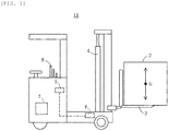
- FIG. 7 illustrates a conventional forklift 1C.
- the forklift 1C includes forks 3 for holding a load 2, cylinders 4 for causing the forks 3 to ascend or descend at a speed corresponding to the flow rate of hydraulic oil, a first valve (e.g., electromagnetic proportional control valve) 5 for controlling the flow rate of hydraulic oil, a second valve (e.g., flow regulator valve) 6 for regulating the flow rate of hydraulic oil between the cylinders 4 and the first valve 5 in accordance with cylinder pressure (the weight of the load 2), a control portion 27 for controlling the first valve 5, and a lift lever 8 for starting/stopping the ascending/descending operation of the forks 3.
- a first valve e.g., electromagnetic proportional control valve
- a second valve e.g., flow regulator valve
- a control portion 27 for controlling the first valve 5
- a lift lever 8 for starting/stopping the ascending/descending operation of the forks 3.
- the cylinders 4 are connected to a hydraulic portion 10 of the forklift 1C via the second valve 6 and the first valve 5, as shown in FIG. 8 .
- the hydraulic portion 10 includes a tank 10A containing the hydraulic oil, a pump 10B for supplying the hydraulic oil in the tank 10A to the first valve 5, a motor 10C for driving the pump 10B, a hydraulic oil supply path, and a hydraulic oil discharge path.
- the control portion 27 includes a current calculation portion 27A for calculating a current command value on the basis of an angle of the lift lever 8, and a current supply portion 27B for supplying the first valve 5 with an energizing current in accordance with the current command value.
- the lever angle is zero when the lift lever 8 is in neutral position. For example, the forks 3 descend when the lever angle is positive, ascend when the lever angle is negative, and stop when the lever angle is zero.
- the forklift 1C has a problem in that the load 2 is vertically vibrated when the ascending/descending operation of the forks 3 is started or stopped.
- a known solution to this problem is an approach to changing the ascending/descending speed of the forks 3 in two stages. This approach cancels out a vibration caused by the first speed change with a vibration caused by the second speed change, and therefore, the load 2 is inhibited from vibrating (e.g., see Patent Document 1).
- the current calculation portion 27A decreases the current command value in two stages. Assuming that the current command value is B3 mA when the lever angle is X, the current calculation portion 27A decreases the current command value by half from B3 mA to B4 mA over a period from time t 1 to time t 1 ', and further decreases the current command value from B4 mA to 0 mA over a period from time t 2 to time t 2 ' (see FIG. 9(B) ).
- the current supply portion 27B decreases the energizing current by half from B3 mA to B4 mA over a period from time t 1 to time t 1 ', and further decreases the energizing current from B4 mA to 0 mA over a period from time t 2 to time t 2 '.
- a first vibration occurs at time t 1 at which the descending speed of the forks 3 is changed for the first time
- a second vibration which is 180° out of phase from the first vibration and has the same amplitude as the first vibration (strictly, a smaller amplitude due to attenuation), occurs at time t 2 at which the descending speed of the forks 3 is changed for the second time (see FIG. 9(C) ). Accordingly, the first vibration is cancelled out by the second vibration, with the result that the load 2 is inhibited from vibrating.
- Patent Document 1 Japanese National Phase PCT Laid-Open Publication No. 2009-542555
- the conventional forklift 1C changes the ascending/descending speed of the forks 3 in two stages regardless of the flow rate of hydraulic oil that is regulated by the second valve 6. Accordingly, when the flow rate of hydraulic oil is regulated by the second valve 6, the first vibration is not sufficiently cancelled out by the second vibration, with the result that the effect of inhibiting the load 2 from vibrating is reduced.
- the present invention has been achieved under the above circumstances, with a problem thereof being to provide a forklift and a fork control method, both of which inhibit load vibration even when the flow rate of hydraulic oil is regulated.
- the present invention provides a forklift including forks for holding a load, cylinders for causing the forks to perform an ascending/descending operation at an ascending/descending speed in accordance with a flow rate of hydraulic oil, a first valve for controlling the flow rate of hydraulic oil in accordance with an energizing current, a second valve for regulating the flow rate of hydraulic oil between the cylinders and the first valve in accordance with cylinder pressure on the cylinders, a control portion for supplying the energizing current to the first valve, an operating portion for stopping the ascending/descending operation, and a pressure sensor for detecting the cylinder pressure, the control portion calculates the flow rate to be regulated by the second valve based on the cylinder pressure, the control portion calculates a current command value for the energizing current, with the flow rate to be controlled by the first valve being set equal to the regulated flow rate, and the control portion changes the energizing current in two stages, with the current command value being set as an upper
- the operating portion causes the ascending/descending operation to start
- the control portion calculates the regulated flow rate based on the cylinder pressure
- the control portion calculates the current command value, with the controlled flow rate being set equal to the regulated flow rate
- the control portion changes the energizing current in two stages, with the current command value being set as the upper limit of the energizing current, thereby accelerating the forks in two stages when starting the ascending/descending operation.
- the control portion calculates a first command value for the energizing current in accordance with an amount of manipulation of the operating portion, when the first command value is greater than a second command value being the current command value, the control portion changes the energizing current in two stages, with the second command value being set as the upper limit of the energizing current, and when the first command value is less than the second command value, the control portion changes the energizing current in two stages, with the first command value being set as the upper limit of the energizing current.
- the forklift can be configured such that the forklift includes a memory portion having first data and second data stored therein, the first data indicating the relationship between the cylinder pressure and the regulated flow rate, the second data indicating the relationship between the energizing current and the controlled flow rate, and the control portion includes a first command calculation portion for calculating the first command value in accordance with the amount of manipulation, a second command calculation portion for calculating the regulated flow rate based on the cylinder pressure and the first data and the second command value based on the regulated flow rate and the second data, and a current supply portion for changing the energizing current in two stages, with the second command value being set as the upper limit of the energizing current when the first command value is greater than the second command value and the first command value being set as the upper limit of the energizing current when the first command value is less than the second command value.
- the forklift can be configured such that the first command calculation portion includes a speed calculation portion for calculating a speed command value for the ascending/descending speed in accordance with the amount of manipulation, and a current calculation portion for calculating the first command value based on the speed command value.
- the present invention provides a method for controlling forks of a forklift including forks for holding a load, cylinders for causing the forks to perform an ascending/descending operation at an ascending/descending speed in accordance with a flow rate of hydraulic oil, a first valve for controlling the flow rate of hydraulic oil in accordance with an energizing current, a second valve for regulating the flow rate of hydraulic oil between the cylinders and the first valve in accordance with cylinder pressure on the cylinders, a control portion for supplying the energizing current to the first valve, and an operating portion for starting and stopping the ascending/descending operation, the method including a first step for the control portion to calculate a first command value for the energizing current in accordance with an amount of manipulation of the operating portion, a second step for the control portion to calculate the flow rate to be regulated by the second valve based on the cylinder pressure, calculate a second command value for the energizing current, with the flow rate to be
- control portion calculate the regulated flow rate based on first data and the second command value based on second data, the first data indicating the relationship between the cylinder pressure and the regulated flow rate, the second data indicating the relationship between the energizing current and the control flow rate.
- the present invention renders it possible to provide a forklift and a fork control method, both of which inhibit load vibration even when the flow rate of hydraulic oil is regulated.
- FIG. 1 illustrates a reach forklift (hereinafter, forklift) 1A according to a first embodiment of the present invention.
- the forklift 1A includes forks 3 for holding a load 2, cylinders 4 for causing the forks 3 to ascend or descend at a speed corresponding to the flow rate of hydraulic oil, a first valve 5, a second valve 6, a control portion 7, and a lift lever 8.
- the lift lever 8 corresponds to the "operating portion" of the present invention.
- the operator of the forklift 1A tilts the lift lever 8 from neutral to ascend position (e.g., backward) in order to start the operation of extending the cylinders 4 and thereby start the ascending operation of the forks 3.
- the operator tilts the lift lever 8 from neutral to descend position (e.g., forward) in order to start the operation of retracting the cylinders 4 and thereby start the descending operation of the forks 3.
- the operator returns the lift lever 8 to the neutral position in order to stop the operation of extending or retracting the cylinders 4 and thereby stop the ascending/descending operation of the forks 3.
- the lift lever 8 includes an angle detection means (e.g., a potentiometer).
- the angle detection means detects the angle (corresponding to the "amount of manipulation" in the present invention) of the lift lever 8 and outputs a signal regarding the lever angle, assuming that the lever angle is 0 when the lift lever 8 is in the neutral position. For example, the lever angle is positive when the forks 3 are descending, negative when the forks 3 are ascending, and 0 when the forks 3 are not moving.
- the forklift 1A further includes a pressure sensor 9 for detecting pressure (cylinder pressure) on the cylinders 4, a hydraulic portion 10, and a memory portion 11, as shown in FIG. 2 .
- the cylinders 4 are connected to the hydraulic portion 10 via the second valve 6 and the first valve 5.
- the first valve 5 is, for example, an electromagnetic proportional control valve and controls the flow rate of hydraulic oil in accordance with an energizing current (e.g., a solenoid current).
- the flow rate (controlled flow rate) of hydraulic oil passing through the first valve 5 increases as the energizing current increases, and also decreases as the energizing current decreases.
- the second valve 6 is, for example, a flow regulator valve and regulates the flow rate of hydraulic oil between the cylinders 4 and the first valve 5 in accordance with cylinder pressure proportional to the weight of the load 2.
- the flow rate regulated by the second valve 6 is lower on the high-pressure side than on the low-pressure side. For example, when the cylinder pressure (the weight of the load 2) is high, the flow rate regulated by the second valve 6 might become lower than the flow rate controlled by the first valve 5.
- the present invention aims to inhibit the load 2 from vibrating in such a case.
- the pressure sensor 9 is a hydraulic pressure sensor for detecting hydraulic pressure (cylinder pressure) between the cylinders 4 and the first valve 5.
- the cylinder pressure increases in proportion to the weight of the load 2.
- the pressure sensor 9 detects cylinder pressure, thereby indirectly detecting the weight of the load 2.
- the pressure sensor 9 outputs a voltage signal having a linear relationship with the detected cylinder pressure to a second command calculation portion 7B of the control portion 7.
- the hydraulic portion 10 includes a tank 10A containing hydraulic oil, a pump 10B for supplying the hydraulic oil in the tank 10A to the first valve 5, a motor 10C for driving the pump 10B, a hydraulic oil supply path, and a hydraulic oil discharge path.
- the control portion 7 is, for example, a control IC (integrated circuit), and includes a first command calculation portion 7A, the second command calculation portion 7B, and a current supply portion 7C.
- the memory portion 11 is, for example, semiconductor memory.
- the memory portion 11 has stored therein data (first data) indicating the relationship between the cylinder pressure and the flow rate to be restricted by the second valve 6, and data (second data) indicating the relationship between the energizing current and the flow rate to be controlled by the first valve 5.
- the first command calculation portion 7A corresponds to the current calculation portion 27A of the conventional forklift 1C.
- the first command calculation portion 7A calculates a first command value for the energizing current in accordance with a lever angle inputted by means of the lift lever 8.
- the first command calculation portion 7A has in advance data indicating the relationship between the lever angle and the first command value, so as to calculate the first command value based on the data upon input of the lever angle. Note that the data may be stored in the memory portion 11.
- the second command calculation portion 7B calculates the flow rate to be regulated by the second valve 6 on the basis of the cylinder pressure and the first data, calculates an energizing current (second command value) from the second data, with the flow rate to be controlled by the first valve 5 being set equal to the regulated flow rate, and compares the first and second command values.
- first command value is less than or equal to the second command value
- a current command value whose upper limit is the first command value is outputted to the current supply portion 7C
- a current command value whose upper limit is the second command value is outputted to the current supply portion 7C.
- the current supply portion 7C changes the energizing current by equal amounts in two stages, with the current command value received from the second command calculation portion 7B being set as the upper limit of the energizing current. As a result, the ascending/descending speed of the forks 3 is changed by equal amounts in two stages.
- the second command calculation portion 7B when the flow rate to be regulated by the second valve 6 is lower than the flow rate to be controlled by the first valve 5, the second command calculation portion 7B outputs the second command value calculated from the cylinder pressure, as a current command value, and the current supply portion 7C changes the energizing current by equal amounts in two stages, with the second command value being set as the upper limit of the energizing current.
- the forklift 1A according to the present embodiment renders it possible to inhibit the load 2 from vibrating even when the flow rate of hydraulic oil is regulated by the second valve 6.
- a fork control method according to the present embodiment, more specifically, a method for controlling the forks of the forklift 1A.
- the fork control method includes a first step in which the first command calculation portion 7A calculates a first command value, a second step in which the second command calculation portion 7B outputs a current command value (first or second command value), and a third step in which the current supply portion 7C changes an energizing current in two stages, with the current command value being set as the upper limit of the energizing current.
- the first through third steps will be specifically described below taking as an example the case where the descending operation of the forks 3 is stopped.
- the angle of the lift lever 8 is X (where X > 0)
- the forks 3 are descending at a speed in accordance with the lever angle X.
- the first command calculation portion 7A calculates a first command value for an energizing current in accordance with the angle of the lift lever 8. Assuming here that the energizing current is B3 mA when the lever angle is X, the first command calculation portion 7A calculates the first command value to be B3 mA. The first command calculation portion 7A outputs the first command value (B3 mA) to the second command calculation portion 7B (the first step ends here).
- the second command calculation portion 7B Upon input of the first command value (B3 mA), as well as cylinder pressure from the pressure sensor 9, the second command calculation portion 7B calculates the flow rate to be regulated by the second valve 6, on the basis of the cylinder pressure and the first data stored in the memory portion 11.
- the second command calculation portion 7B calculates the flow rate to be regulated by the second valve 6 to be F1 l/min.
- the second command calculation portion 7B calculates an energizing current (second command value) from the second data stored in the memory portion 11, with the control flow rate for the first valve 5 being set equal to the regulated flow rate (F1 l/min).
- the second command calculation portion 7B calculates the second command value to be B1 mA.
- the second command calculation portion 7B compares the first command value (B3 mA) with the second command value (B1 mA). When the first command value (B3 mA) is greater than the second command value (B1 mA), the second command calculation portion 7B outputs the second command value (B1 mA) to the current supply portion 7C as a current command value.
- the second command calculation portion 7B performs an operation to subtract the second command value from the first command value, and when the operation result is positive, a value obtained by subtracting the operation result from the first command value, i.e., the second command value, is outputted to the current supply portion 7C as a current command value.
- the second command calculation portion 7B outputs the first command value to the current supply portion 7C as a current command value (the second
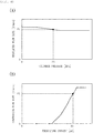
- the second command calculation portion 7B changes the current command value in two stages, as shown in FIG. 3(B) .
- the second command calculation portion 7B decreases the current command value by half from B1 mA to B2 mA over a period from time t 1 to time t 1 ', and further decreases the current command value from B2 mA to 0 mA over a period from time t 2 to time t 2 '.
- the current supply portion 7C decreases the energizing current by half from B1 mA to B2 mA over a period from time t 1 to time t 1 ', and further decreases the energizing current from B2 mA to 0 mA over a period from time t 2 to time t 2 ' (the third step ends here).
- time t 2 is the time at which the displacement of a first vibration makes the first return to 0, as shown in FIG. 3(C) .
- the first vibration is a vibration caused at the center of gravity G of the load 2 at time t 1 at which the descending speed of the forks 3 is changed for the first time.
- a second vibration is caused at the center of gravity G of the load 2.
- the vibration data for the first vibration is data regarding, for example, relations of the phase and the amplitude of the first vibration with the cylinder pressure and the energizing current.
- the vibration data for the second vibration is data regarding, for example, relations of the phase and the amplitude of the second vibration with the cylinder pressure and the energizing current.
- the second command calculation portion 7B decides at time t 1 the time (time t 2 ) to change the descending speed of the forks 3 for the second time.
- the second command calculation portion 7B when the flow rate to be regulated by the second valve 6 is lower than the flow rate to be controlled by the first valve 5, the second command calculation portion 7B outputs the second command value, which is calculated from the cylinder pressure, as the current command value, and the current supply portion 7C changes the energizing current by equal amounts in two stages, with the second command value being set as the upper limit of the energizing current.
- the fork control method according to the present embodiment renders it possible to inhibit the load 2 from vibrating even when the flow rate of hydraulic oil is regulated by the second valve 6.
- the load 2 can also be inhibited from vibrating in the cases where the descending operation of the forks 3 is started, or the ascending operation of the forks 3 is started or stopped.
- FIG. 5 illustrates a forklift 1B according to a second embodiment of the present invention.
- the forklift 1B differs from the first embodiment only in the configuration of the control portion 17. Specifically, the difference from the first embodiment is that the first command calculation portion 17A of the control portion 17 consists of a speed calculation portion and a current calculation portion, as shown in FIG. 6 .
- the speed calculation portion calculates a speed command value for the forks 3 in accordance with a lever angle inputted by means of the lift lever 8.
- the speed calculation portion has in advance data indicating the relationship between the lever angle and the speed command value, and once the lever angle is inputted, the speed calculation portion calculates the speed command value on the basis of the data. Note that the data may be stored in the memory portion 11.
- the current calculation portion calculates the first command value for the energizing current.
- the current calculation portion has in advance data indicating the relationship between the speed command value and the first command value, and once the speed command value is inputted, the current calculation portion calculates the first command value on the basis of the data. Note that the data may be stored in the memory portion 11.
- the amplitude of the first and second vibrations caused at the center of gravity G of the load 2 has a linear relationship with the speed of the forks 3.
- the speed of the forks 3 has a linear relationship with the amount of hydraulic oil supplied/discharged by the first valve 5.
- the supplied/discharged amount has a non-linear relationship with the energizing current, and therefore, even when the energizing current is halved by halving the current command value, the amount supplied/discharged (the descending speed of the forks 3) might not be halved. That is, in some cases, the first and second vibrations cannot be equalized in amplitude, and in such a case, the first vibration cannot be efficiently cancelled out by the second vibration, with the result that the vibration of the load 2 might not be sufficiently reduced.
- the speed calculation portion calculates the speed command value for the forks 3 that has a linear relationship with the vibration amplitude, and therefore, the first and second vibrations can be readily equalized in amplitude.
- the forklift 1B according to the present embodiment renders it possible to inhibit the load 2 from vibrating even when the flow rate of hydraulic oil is regulated by the second valve 6.
- a fork control method i.e., a method for controlling the forks of the forklift 1B.
- the fork control method shares similarity with the first embodiment in that the method includes a first step in which the first command calculation portion 17A calculates the first command value, a second step in which the second command calculation portion 17B outputs the current command value (first or second command value), and a third step in which the current supply portion 17C changes the energizing current in two stages, with the current command value being set as the upper limit of the energizing current.
- the fork control method differs from the first embodiment in that, in the first step, the speed calculation portion calculates the speed command value for the forks 3, and the current calculation portion calculates the first command value on the basis of the speed command value.
- the speed calculation portion calculates the speed command value for the forks 3 that has a linear relationship with the vibration amplitude, and therefore, the first and second vibrations can be readily equalized in amplitude.
- the fork control method according to the present embodiment renders it possible to inhibit the load 2 from vibrating even when the flow rate of hydraulic oil is regulated by the second valve 6.
- the forklift and the fork control method according to the present invention are simply required to decelerate the forks 3 in two stages at least when stopping the ascending/descending operation of the forks 3.
- the rate of changing the speed at the time of decelerating (or accelerating) the forks 3 in two stages can be suitably changed.
- the time during which to change the speed may be shortened as much as possible, so that the forks 3 descend (or ascend) swiftly in two stages. This results in a reduced delay in movement of the forks 3 when starting the ascending/descending operation.
- the current supply portion 7C changes the energizing current by equal amounts in two stages, with the current command value received from the second command calculation portion 7B being set as the upper limit of the energizing current, but the energizing current does not have to be changed by equal amounts.
- the current command value may be decreased from B1 mA to B2-5 mA in the first stage (over a period from time t 1 to time t 1 ') and further from B2-5 mA to 0 mA in the second stage (over a period from time t 2 to time t 2 ').
- the first valve 5 can be suitably changed in configuration so long as the flow rate of hydraulic oil is controlled in accordance with the energizing current.
- the second valve 6 can be suitably changed in configuration so long as the flow rate of hydraulic oil between the cylinders 4 and the first valve 5 is regulated in accordance with the cylinder pressure.
- control portions 7 and 17 can be suitably changed in configuration so long as the flow rate to be regulated by the second valve 6 is calculated on the basis of the cylinder pressure, the current command value for the energizing current is calculated with the flow rate to be controlled by the first valve 5 being set equal to the regulated flow rate, and the energizing current is changed in two stages, with the current command value being set as the upper limit of the energizing current.
- the forklift according to the present invention encompasses other forklifts besides the reach forklift.
Landscapes
- Engineering & Computer Science (AREA)
- Structural Engineering (AREA)
- Transportation (AREA)
- Mechanical Engineering (AREA)
- Life Sciences & Earth Sciences (AREA)
- Civil Engineering (AREA)
- Geology (AREA)
- Physics & Mathematics (AREA)
- Fluid Mechanics (AREA)
- General Engineering & Computer Science (AREA)
- Chemical & Material Sciences (AREA)
- Combustion & Propulsion (AREA)
- Forklifts And Lifting Vehicles (AREA)
Applications Claiming Priority (1)
| Application Number | Priority Date | Filing Date | Title |
|---|---|---|---|
| PCT/JP2016/087727 WO2018116336A1 (ja) | 2016-12-19 | 2016-12-19 | フォークリフトおよびフォーク制御方法 |
Publications (3)
| Publication Number | Publication Date |
|---|---|
| EP3556721A1 true EP3556721A1 (de) | 2019-10-23 |
| EP3556721A4 EP3556721A4 (de) | 2020-09-02 |
| EP3556721B1 EP3556721B1 (de) | 2023-03-15 |
Family
ID=62627173
Family Applications (1)
| Application Number | Title | Priority Date | Filing Date |
|---|---|---|---|
| EP16924591.7A Active EP3556721B1 (de) | 2016-12-19 | 2016-12-19 | Gabelstapler und steuerungsverfahren für gabelstapler |
Country Status (6)
| Country | Link |
|---|---|
| US (1) | US10752480B2 (de) |
| EP (1) | EP3556721B1 (de) |
| JP (1) | JP6760703B2 (de) |
| KR (1) | KR102180583B1 (de) |
| CN (1) | CN110088036B (de) |
| WO (1) | WO2018116336A1 (de) |
Families Citing this family (5)
| Publication number | Priority date | Publication date | Assignee | Title |
|---|---|---|---|---|
| CN114506800B (zh) * | 2022-04-20 | 2022-07-05 | 杭叉集团股份有限公司 | 一种电动叉车门架动作控制系统 |
| US12329284B2 (en) | 2023-02-08 | 2025-06-17 | L&P Property Management Company | Adjustable bed base with decline feature on both ends |
| CN117585532B (zh) * | 2023-11-29 | 2026-03-10 | 江苏星基智能装备有限公司 | 一种对接agv的动力放线机 |
| CN118405637B (zh) * | 2024-07-01 | 2024-08-23 | 杭叉集团股份有限公司 | 一种低位拣选车的控制方法、装置及低位拣选车 |
| CN119244611B (zh) * | 2024-11-04 | 2025-05-16 | 深圳市深空无限科技有限公司 | 一种工程作业车辆载重的分析方法 |
Family Cites Families (15)
| Publication number | Priority date | Publication date | Assignee | Title |
|---|---|---|---|---|
| DE3711233A1 (de) * | 1987-04-03 | 1988-10-20 | Linde Ag | Antriebseinrichtung mit einer primaerenergiequelle, einem getriebe und einer pumpe |
| US5287699A (en) * | 1990-01-16 | 1994-02-22 | Kabushiki Kaisha Komatsu Seisakusho | Automatic vibration method and device for hydraulic drilling machine |
| JPH08282995A (ja) * | 1995-04-14 | 1996-10-29 | Nippon Yusoki Co Ltd | フオークリフトトラックの荷役制御装置 |
| JP3602006B2 (ja) * | 1999-06-30 | 2004-12-15 | 小松フォークリフト株式会社 | フォークリフトの荷役シリンダの制御装置 |
| JP3676127B2 (ja) | 1999-06-30 | 2005-07-27 | 小松フォークリフト株式会社 | フォークリフトの荷役制御装置 |
| JP2001261295A (ja) * | 2000-03-17 | 2001-09-26 | Komatsu Forklift Co Ltd | フォークリフトトラックのリフトシリンダの制御装置 |
| JP2002354883A (ja) * | 2001-05-22 | 2002-12-06 | Moric Co Ltd | 電動アクチュエータ |
| WO2008006928A1 (en) | 2006-07-12 | 2008-01-17 | Rocla Oyj | A method and an arrangement for dampening vibrations in a mast structure |
| EP2549642A1 (de) * | 2010-03-17 | 2013-01-23 | Hitachi Construction Machinery Co., Ltd. | Aktuatorsteuerungsvorrichtung und damit ausgestattete arbeitsmaschine |
| CN202107486U (zh) * | 2011-05-16 | 2012-01-11 | 衡阳三创工程机械有限公司 | 防下砸的叉车吊具系统 |
| JP5902474B2 (ja) * | 2011-12-28 | 2016-04-13 | ニチユ三菱フォークリフト株式会社 | 産業用車両 |
| JP5567608B2 (ja) * | 2012-02-10 | 2014-08-06 | ニチユ三菱フォークリフト株式会社 | 産業用車両 |
| JP6269170B2 (ja) * | 2013-06-17 | 2018-01-31 | 株式会社豊田自動織機 | 荷役車両の油圧駆動装置 |
| KR101621675B1 (ko) * | 2013-12-06 | 2016-05-16 | 가부시키가이샤 고마쓰 세이사쿠쇼 | 유압 셔블 |
| CN205273603U (zh) * | 2015-12-04 | 2016-06-01 | 安徽合叉叉车有限公司 | 液压泵和转向泵合一的蓄电池电动叉车 |
-
2016
- 2016-12-19 WO PCT/JP2016/087727 patent/WO2018116336A1/ja not_active Ceased
- 2016-12-19 KR KR1020197017667A patent/KR102180583B1/ko active Active
- 2016-12-19 EP EP16924591.7A patent/EP3556721B1/de active Active
- 2016-12-19 JP JP2018557236A patent/JP6760703B2/ja active Active
- 2016-12-19 US US16/465,182 patent/US10752480B2/en active Active
- 2016-12-19 CN CN201680091724.9A patent/CN110088036B/zh active Active
Also Published As
| Publication number | Publication date |
|---|---|
| CN110088036A (zh) | 2019-08-02 |
| EP3556721A4 (de) | 2020-09-02 |
| US20200002144A1 (en) | 2020-01-02 |
| EP3556721B1 (de) | 2023-03-15 |
| KR20190085990A (ko) | 2019-07-19 |
| JPWO2018116336A1 (ja) | 2019-06-24 |
| WO2018116336A1 (ja) | 2018-06-28 |
| US10752480B2 (en) | 2020-08-25 |
| CN110088036B (zh) | 2020-09-25 |
| JP6760703B2 (ja) | 2020-09-23 |
| KR102180583B1 (ko) | 2020-11-18 |
Similar Documents
| Publication | Publication Date | Title |
|---|---|---|
| EP3556721A1 (de) | Gabelstapler und steuerungsverfahren für gabelstapler | |
| US9020708B2 (en) | Drive control method of operating machine | |
| CN104986675B (zh) | 一种臂架变幅液压系统和起重机 | |
| US20130125537A1 (en) | Swirl flow control system for construction equipment and method of controlling the same | |
| EP3575614B1 (de) | Arbeitsmaschine | |
| US11454002B2 (en) | Hydraulic drive system for work machine | |
| KR20100129995A (ko) | 건설기계의 선회제어장치 및 선회제어방법 | |
| US10626000B2 (en) | Industrial vehicle | |
| US10183851B2 (en) | Cargo vehicle | |
| KR102054519B1 (ko) | 건설기계의 유압시스템 | |
| US20170037600A1 (en) | Drive control device for construction equipment and control method therefor | |
| US9959963B2 (en) | Current controller | |
| TWI490423B (zh) | 裝卸載控制裝置 | |
| WO2018092505A1 (ja) | 荷役車両の油圧駆動装置 | |
| JP2010247984A (ja) | フォークリフト用油圧回路制御システム | |
| KR102478297B1 (ko) | 건설기계의 제어장치 및 제어방법 | |
| JP5752129B2 (ja) | 設定可能なアクティブジャーク制御 | |
| JP2000355497A (ja) | フォークリフトトラックの荷役用シリンダの制御装置 | |
| JP6488990B2 (ja) | 荷役車両の油圧駆動装置 | |
| KR20080040861A (ko) | 지게차의 포크 높이 감응 틸트유량 조절장치 | |
| JP2000044199A (ja) | リーチフォークリフトのリーチ制御装置 | |
| WO2018092509A1 (ja) | 荷役車両の油圧駆動装置 | |
| JP2013203510A (ja) | 産業車両の荷役制御装置 |
Legal Events
| Date | Code | Title | Description |
|---|---|---|---|
| STAA | Information on the status of an ep patent application or granted ep patent |
Free format text: STATUS: THE INTERNATIONAL PUBLICATION HAS BEEN MADE |
|
| PUAI | Public reference made under article 153(3) epc to a published international application that has entered the european phase |
Free format text: ORIGINAL CODE: 0009012 |
|
| STAA | Information on the status of an ep patent application or granted ep patent |
Free format text: STATUS: REQUEST FOR EXAMINATION WAS MADE |
|
| 17P | Request for examination filed |
Effective date: 20190606 |
|
| AK | Designated contracting states |
Kind code of ref document: A1 Designated state(s): AL AT BE BG CH CY CZ DE DK EE ES FI FR GB GR HR HU IE IS IT LI LT LU LV MC MK MT NL NO PL PT RO RS SE SI SK SM TR |
|
| AX | Request for extension of the european patent |
Extension state: BA ME |
|
| DAV | Request for validation of the european patent (deleted) | ||
| DAX | Request for extension of the european patent (deleted) | ||
| A4 | Supplementary search report drawn up and despatched |
Effective date: 20200731 |
|
| RIC1 | Information provided on ipc code assigned before grant |
Ipc: B66F 9/22 20060101AFI20200727BHEP |
|
| GRAP | Despatch of communication of intention to grant a patent |
Free format text: ORIGINAL CODE: EPIDOSNIGR1 |
|
| STAA | Information on the status of an ep patent application or granted ep patent |
Free format text: STATUS: GRANT OF PATENT IS INTENDED |
|
| INTG | Intention to grant announced |
Effective date: 20221014 |
|
| GRAS | Grant fee paid |
Free format text: ORIGINAL CODE: EPIDOSNIGR3 |
|
| GRAA | (expected) grant |
Free format text: ORIGINAL CODE: 0009210 |
|
| STAA | Information on the status of an ep patent application or granted ep patent |
Free format text: STATUS: THE PATENT HAS BEEN GRANTED |
|
| AK | Designated contracting states |
Kind code of ref document: B1 Designated state(s): AL AT BE BG CH CY CZ DE DK EE ES FI FR GB GR HR HU IE IS IT LI LT LU LV MC MK MT NL NO PL PT RO RS SE SI SK SM TR |
|
| REG | Reference to a national code |
Ref country code: CH Ref legal event code: EP Ref country code: GB Ref legal event code: FG4D |
|
| REG | Reference to a national code |
Ref country code: DE Ref legal event code: R096 Ref document number: 602016078389 Country of ref document: DE |
|
| REG | Reference to a national code |
Ref country code: IE Ref legal event code: FG4D |
|
| REG | Reference to a national code |
Ref country code: AT Ref legal event code: REF Ref document number: 1553926 Country of ref document: AT Kind code of ref document: T Effective date: 20230415 |
|
| P01 | Opt-out of the competence of the unified patent court (upc) registered |
Effective date: 20230509 |
|
| REG | Reference to a national code |
Ref country code: LT Ref legal event code: MG9D |
|
| REG | Reference to a national code |
Ref country code: NL Ref legal event code: MP Effective date: 20230315 |
|
| PG25 | Lapsed in a contracting state [announced via postgrant information from national office to epo] |
Ref country code: RS Free format text: LAPSE BECAUSE OF FAILURE TO SUBMIT A TRANSLATION OF THE DESCRIPTION OR TO PAY THE FEE WITHIN THE PRESCRIBED TIME-LIMIT Effective date: 20230315 Ref country code: NO Free format text: LAPSE BECAUSE OF FAILURE TO SUBMIT A TRANSLATION OF THE DESCRIPTION OR TO PAY THE FEE WITHIN THE PRESCRIBED TIME-LIMIT Effective date: 20230615 Ref country code: LV Free format text: LAPSE BECAUSE OF FAILURE TO SUBMIT A TRANSLATION OF THE DESCRIPTION OR TO PAY THE FEE WITHIN THE PRESCRIBED TIME-LIMIT Effective date: 20230315 Ref country code: LT Free format text: LAPSE BECAUSE OF FAILURE TO SUBMIT A TRANSLATION OF THE DESCRIPTION OR TO PAY THE FEE WITHIN THE PRESCRIBED TIME-LIMIT Effective date: 20230315 Ref country code: HR Free format text: LAPSE BECAUSE OF FAILURE TO SUBMIT A TRANSLATION OF THE DESCRIPTION OR TO PAY THE FEE WITHIN THE PRESCRIBED TIME-LIMIT Effective date: 20230315 |
|
| REG | Reference to a national code |
Ref country code: AT Ref legal event code: MK05 Ref document number: 1553926 Country of ref document: AT Kind code of ref document: T Effective date: 20230315 |
|
| PG25 | Lapsed in a contracting state [announced via postgrant information from national office to epo] |
Ref country code: SE Free format text: LAPSE BECAUSE OF FAILURE TO SUBMIT A TRANSLATION OF THE DESCRIPTION OR TO PAY THE FEE WITHIN THE PRESCRIBED TIME-LIMIT Effective date: 20230315 Ref country code: NL Free format text: LAPSE BECAUSE OF FAILURE TO SUBMIT A TRANSLATION OF THE DESCRIPTION OR TO PAY THE FEE WITHIN THE PRESCRIBED TIME-LIMIT Effective date: 20230315 Ref country code: GR Free format text: LAPSE BECAUSE OF FAILURE TO SUBMIT A TRANSLATION OF THE DESCRIPTION OR TO PAY THE FEE WITHIN THE PRESCRIBED TIME-LIMIT Effective date: 20230616 Ref country code: FI Free format text: LAPSE BECAUSE OF FAILURE TO SUBMIT A TRANSLATION OF THE DESCRIPTION OR TO PAY THE FEE WITHIN THE PRESCRIBED TIME-LIMIT Effective date: 20230315 |
|
| PG25 | Lapsed in a contracting state [announced via postgrant information from national office to epo] |
Ref country code: SM Free format text: LAPSE BECAUSE OF FAILURE TO SUBMIT A TRANSLATION OF THE DESCRIPTION OR TO PAY THE FEE WITHIN THE PRESCRIBED TIME-LIMIT Effective date: 20230315 Ref country code: RO Free format text: LAPSE BECAUSE OF FAILURE TO SUBMIT A TRANSLATION OF THE DESCRIPTION OR TO PAY THE FEE WITHIN THE PRESCRIBED TIME-LIMIT Effective date: 20230315 Ref country code: PT Free format text: LAPSE BECAUSE OF FAILURE TO SUBMIT A TRANSLATION OF THE DESCRIPTION OR TO PAY THE FEE WITHIN THE PRESCRIBED TIME-LIMIT Effective date: 20230717 Ref country code: ES Free format text: LAPSE BECAUSE OF FAILURE TO SUBMIT A TRANSLATION OF THE DESCRIPTION OR TO PAY THE FEE WITHIN THE PRESCRIBED TIME-LIMIT Effective date: 20230315 Ref country code: EE Free format text: LAPSE BECAUSE OF FAILURE TO SUBMIT A TRANSLATION OF THE DESCRIPTION OR TO PAY THE FEE WITHIN THE PRESCRIBED TIME-LIMIT Effective date: 20230315 Ref country code: CZ Free format text: LAPSE BECAUSE OF FAILURE TO SUBMIT A TRANSLATION OF THE DESCRIPTION OR TO PAY THE FEE WITHIN THE PRESCRIBED TIME-LIMIT Effective date: 20230315 Ref country code: AT Free format text: LAPSE BECAUSE OF FAILURE TO SUBMIT A TRANSLATION OF THE DESCRIPTION OR TO PAY THE FEE WITHIN THE PRESCRIBED TIME-LIMIT Effective date: 20230315 |
|
| PG25 | Lapsed in a contracting state [announced via postgrant information from national office to epo] |
Ref country code: SK Free format text: LAPSE BECAUSE OF FAILURE TO SUBMIT A TRANSLATION OF THE DESCRIPTION OR TO PAY THE FEE WITHIN THE PRESCRIBED TIME-LIMIT Effective date: 20230315 Ref country code: PL Free format text: LAPSE BECAUSE OF FAILURE TO SUBMIT A TRANSLATION OF THE DESCRIPTION OR TO PAY THE FEE WITHIN THE PRESCRIBED TIME-LIMIT Effective date: 20230315 Ref country code: IS Free format text: LAPSE BECAUSE OF FAILURE TO SUBMIT A TRANSLATION OF THE DESCRIPTION OR TO PAY THE FEE WITHIN THE PRESCRIBED TIME-LIMIT Effective date: 20230715 |
|
| REG | Reference to a national code |
Ref country code: DE Ref legal event code: R097 Ref document number: 602016078389 Country of ref document: DE |
|
| PLBE | No opposition filed within time limit |
Free format text: ORIGINAL CODE: 0009261 |
|
| STAA | Information on the status of an ep patent application or granted ep patent |
Free format text: STATUS: NO OPPOSITION FILED WITHIN TIME LIMIT |
|
| PG25 | Lapsed in a contracting state [announced via postgrant information from national office to epo] |
Ref country code: SI Free format text: LAPSE BECAUSE OF FAILURE TO SUBMIT A TRANSLATION OF THE DESCRIPTION OR TO PAY THE FEE WITHIN THE PRESCRIBED TIME-LIMIT Effective date: 20230315 Ref country code: DK Free format text: LAPSE BECAUSE OF FAILURE TO SUBMIT A TRANSLATION OF THE DESCRIPTION OR TO PAY THE FEE WITHIN THE PRESCRIBED TIME-LIMIT Effective date: 20230315 |
|
| 26N | No opposition filed |
Effective date: 20231218 |
|
| REG | Reference to a national code |
Ref country code: CH Ref legal event code: PL |
|
| PG25 | Lapsed in a contracting state [announced via postgrant information from national office to epo] |
Ref country code: LU Free format text: LAPSE BECAUSE OF NON-PAYMENT OF DUE FEES Effective date: 20231219 |
|
| PG25 | Lapsed in a contracting state [announced via postgrant information from national office to epo] |
Ref country code: MC Free format text: LAPSE BECAUSE OF FAILURE TO SUBMIT A TRANSLATION OF THE DESCRIPTION OR TO PAY THE FEE WITHIN THE PRESCRIBED TIME-LIMIT Effective date: 20230315 |
|
| REG | Reference to a national code |
Ref country code: BE Ref legal event code: MM Effective date: 20231231 |
|
| PG25 | Lapsed in a contracting state [announced via postgrant information from national office to epo] |
Ref country code: MC Free format text: LAPSE BECAUSE OF FAILURE TO SUBMIT A TRANSLATION OF THE DESCRIPTION OR TO PAY THE FEE WITHIN THE PRESCRIBED TIME-LIMIT Effective date: 20230315 Ref country code: LU Free format text: LAPSE BECAUSE OF NON-PAYMENT OF DUE FEES Effective date: 20231219 |
|
| REG | Reference to a national code |
Ref country code: IE Ref legal event code: MM4A |
|
| PG25 | Lapsed in a contracting state [announced via postgrant information from national office to epo] |
Ref country code: IE Free format text: LAPSE BECAUSE OF NON-PAYMENT OF DUE FEES Effective date: 20231219 |
|
| PG25 | Lapsed in a contracting state [announced via postgrant information from national office to epo] |
Ref country code: BE Free format text: LAPSE BECAUSE OF NON-PAYMENT OF DUE FEES Effective date: 20231231 |
|
| PG25 | Lapsed in a contracting state [announced via postgrant information from national office to epo] |
Ref country code: CH Free format text: LAPSE BECAUSE OF NON-PAYMENT OF DUE FEES Effective date: 20231231 |
|
| PG25 | Lapsed in a contracting state [announced via postgrant information from national office to epo] |
Ref country code: IE Free format text: LAPSE BECAUSE OF NON-PAYMENT OF DUE FEES Effective date: 20231219 Ref country code: CH Free format text: LAPSE BECAUSE OF NON-PAYMENT OF DUE FEES Effective date: 20231231 Ref country code: BE Free format text: LAPSE BECAUSE OF NON-PAYMENT OF DUE FEES Effective date: 20231231 |
|
| PG25 | Lapsed in a contracting state [announced via postgrant information from national office to epo] |
Ref country code: BG Free format text: LAPSE BECAUSE OF FAILURE TO SUBMIT A TRANSLATION OF THE DESCRIPTION OR TO PAY THE FEE WITHIN THE PRESCRIBED TIME-LIMIT Effective date: 20230315 |
|
| PG25 | Lapsed in a contracting state [announced via postgrant information from national office to epo] |
Ref country code: BG Free format text: LAPSE BECAUSE OF FAILURE TO SUBMIT A TRANSLATION OF THE DESCRIPTION OR TO PAY THE FEE WITHIN THE PRESCRIBED TIME-LIMIT Effective date: 20230315 |
|
| PG25 | Lapsed in a contracting state [announced via postgrant information from national office to epo] |
Ref country code: CY Free format text: LAPSE BECAUSE OF FAILURE TO SUBMIT A TRANSLATION OF THE DESCRIPTION OR TO PAY THE FEE WITHIN THE PRESCRIBED TIME-LIMIT; INVALID AB INITIO Effective date: 20161219 |
|
| PG25 | Lapsed in a contracting state [announced via postgrant information from national office to epo] |
Ref country code: HU Free format text: LAPSE BECAUSE OF FAILURE TO SUBMIT A TRANSLATION OF THE DESCRIPTION OR TO PAY THE FEE WITHIN THE PRESCRIBED TIME-LIMIT; INVALID AB INITIO Effective date: 20161219 |
|
| PG25 | Lapsed in a contracting state [announced via postgrant information from national office to epo] |
Ref country code: TR Free format text: LAPSE BECAUSE OF FAILURE TO SUBMIT A TRANSLATION OF THE DESCRIPTION OR TO PAY THE FEE WITHIN THE PRESCRIBED TIME-LIMIT Effective date: 20230315 |
|
| PGFP | Annual fee paid to national office [announced via postgrant information from national office to epo] |
Ref country code: DE Payment date: 20251028 Year of fee payment: 10 |
|
| PGFP | Annual fee paid to national office [announced via postgrant information from national office to epo] |
Ref country code: GB Payment date: 20251030 Year of fee payment: 10 |
|
| PGFP | Annual fee paid to national office [announced via postgrant information from national office to epo] |
Ref country code: IT Payment date: 20251121 Year of fee payment: 10 |
|
| PGFP | Annual fee paid to national office [announced via postgrant information from national office to epo] |
Ref country code: FR Payment date: 20251110 Year of fee payment: 10 |